US4736826A - Remotely controlled and/or powered mobile robot with cable management arrangement - Google Patents
Remotely controlled and/or powered mobile robot with cable management arrangementDownload PDFInfo
- Publication number
- US4736826A US4736826AUS06/726,012US72601285AUS4736826AUS 4736826 AUS4736826 AUS 4736826AUS 72601285 AUS72601285 AUS 72601285AUS 4736826 AUS4736826 AUS 4736826A
- Authority
- US
- United States
- Prior art keywords
- cable
- robot
- mobile robot
- reel
- station
- Prior art date
- Legal status (The legal status is an assumption and is not a legal conclusion. Google has not performed a legal analysis and makes no representation as to the accuracy of the status listed.)
- Expired - Fee Related
Links
Images


Classifications
- B—PERFORMING OPERATIONS; TRANSPORTING
- B25—HAND TOOLS; PORTABLE POWER-DRIVEN TOOLS; MANIPULATORS
- B25J—MANIPULATORS; CHAMBERS PROVIDED WITH MANIPULATION DEVICES
- B25J5/00—Manipulators mounted on wheels or on carriages
- B25J5/007—Manipulators mounted on wheels or on carriages mounted on wheels
- B—PERFORMING OPERATIONS; TRANSPORTING
- B25—HAND TOOLS; PORTABLE POWER-DRIVEN TOOLS; MANIPULATORS
- B25J—MANIPULATORS; CHAMBERS PROVIDED WITH MANIPULATION DEVICES
- B25J19/00—Accessories fitted to manipulators, e.g. for monitoring, for viewing; Safety devices combined with or specially adapted for use in connection with manipulators
- B25J19/0025—Means for supplying energy to the end effector
- B25J19/0029—Means for supplying energy to the end effector arranged within the different robot elements
- B—PERFORMING OPERATIONS; TRANSPORTING
- B25—HAND TOOLS; PORTABLE POWER-DRIVEN TOOLS; MANIPULATORS
- B25J—MANIPULATORS; CHAMBERS PROVIDED WITH MANIPULATION DEVICES
- B25J9/00—Programme-controlled manipulators
- B25J9/0003—Home robots, i.e. small robots for domestic use
- G—PHYSICS
- G05—CONTROLLING; REGULATING
- G05D—SYSTEMS FOR CONTROLLING OR REGULATING NON-ELECTRIC VARIABLES
- G05D1/00—Control of position, course, altitude or attitude of land, water, air or space vehicles, e.g. using automatic pilots
- G05D1/02—Control of position or course in two dimensions
- G05D1/021—Control of position or course in two dimensions specially adapted to land vehicles
- G05D1/0268—Control of position or course in two dimensions specially adapted to land vehicles using internal positioning means
- G05D1/0272—Control of position or course in two dimensions specially adapted to land vehicles using internal positioning means comprising means for registering the travel distance, e.g. revolutions of wheels
- G—PHYSICS
- G21—NUCLEAR PHYSICS; NUCLEAR ENGINEERING
- G21F—PROTECTION AGAINST X-RADIATION, GAMMA RADIATION, CORPUSCULAR RADIATION OR PARTICLE BOMBARDMENT; TREATING RADIOACTIVELY CONTAMINATED MATERIAL; DECONTAMINATION ARRANGEMENTS THEREFOR
- G21F7/00—Shielded cells or rooms
- G21F7/06—Structural combination with remotely-controlled apparatus, e.g. with manipulators
- H—ELECTRICITY
- H02—GENERATION; CONVERSION OR DISTRIBUTION OF ELECTRIC POWER
- H02G—INSTALLATION OF ELECTRIC CABLES OR LINES, OR OF COMBINED OPTICAL AND ELECTRIC CABLES OR LINES
- H02G11/00—Arrangements of electric cables or lines between relatively-movable parts
- H02G11/02—Arrangements of electric cables or lines between relatively-movable parts using take-up reel or drum
Definitions
- This inventionrelates to mobile robots using a cable connected to a remote source for supplying control signals and/or power.
- a primary use under considerationis for the purpose of surveillance and inspection in nuclear power plants so as to reduce the radiation exposure of workers.
- experience with robotics at automated manufacturing plantsindicate that man hours and time required to do work can also be decreased and worker safety and work quality improved.
- mobile robotscould be used in place of security guards, in hazardous areas of chemical processing plants, and to perform some of the hazardous jobs of soldiers, such as mine field clearing. Numerous other tasks could be performed by remotely controlled and/or powered mobile robots to decrease a worker's exposure to bodily harm and unhealthy environments as well as relieve a worker from monotonous and unproductive jobs.
- the mobile robot of this inventionis of a type that permits a human to intervene in the control loop so as to be able to maneuver the robot from a remote location. Provisions may also be made for the robot to repeat its activity or perform various other programming tasks automatically and autonomously. Sometimes robots of the type shown herein are referred to as teleoperated mobile units or teleoperated mobile manipulators when the robot carries a robotic arm or other device that can be used for remote manipulation.
- the robot system as shown hereinis made up of three major components.
- the major componentis the mobile robot itself which is operatively connected through a cable to the inside of a containment box which is in turn operated through another cable to a control console.
- the control consoleitself is not a part of this invention, and can be of any suitable type depending on the use of the robot and the various features desired.
- the mobile robotis of circular configuration with a base member containing six rechargeable batteries driving the variable speed, reversible electric gear motors which in turn drive two drive wheels.
- a third swivel wheelis also provided which is not driven. All the wheels are eight inches in diameter and are designed so they can go over obstacles at least two inches high and can go through at least three inches of water.
- the three wheelsare placed substantially entirely within the periphery of the diameter of the base member which is thirty inches.
- the two drive wheelsare independent of one another so that if one is going one direction and the other going the other direction, the robot can turn almost within its own diameter and negotiate obstacles in a labrynth or maze representative of the kind of conditions often found in nuclear power plants.
- Each of the geared drive motors for the drive wheelshave associated with them optical encoders which serve as position indicators for the robot as the rotations are followed and calculated using well known methods by a control computer associated with the system to indicated the amount and direction of travel.
- the encodersfurnish a thousand bits per rotation which translates into 0.025 inches of linear travel per bit, and the robot can return to an original location usually within one-eighth to one-fourth inch accuracy.
- the cable handling and storage assembly or reel assemblystores the cable on a reel which is driven by a gear motor through a chain and sprocket arrangement.
- the reel in one arrangementcontains one hundred fifty feet of cable which is made up of thirteen twisted wire pairs.
- the twisted wire pairsmay be dedicated one each for video, audio, intercom and deadman and two for telemetry and seven for electrical power.
- the cableis 0.48 inches in diameter and for application in a nuclear power plant this length is sufficient.
- a position sensorwhich is a potentiometer furnishing a continuous inventory of the amount of cable dispensed versus the cable still on the reel.
- the cable handling and storage arrangementalso includes a cable feed which consists of a pulley or sheave having a groove which is shallower than the 0.48 inch diameter of the cable.
- the cableis pressed into the groove by a spring tensioner or friction generator and adjusted so that about twenty-three pounds of pressure is applied to the cable so that friction between the cable and sheave is increased when the sheave rotates to move the cable. This amount of pressure could be reduced and, of course, is varied under the circumstances, type of cable used, and the like.
- the part of the spring tensioner that serves as a friction generator in pressure contact with the cableis a nylon rotating member whose flat face is wider than the sheave with flanges to prevent the cable from moving off of the face.
- the rotation of the drive wheelsis indicated by the optical encoders.
- Such indicationis translated into an indication of movement of the robot.
- This informationis used to feed signals to the cable feed drive motor to cause the cable to be fed out or dispensed at the same rate as the robot is moving so that there is no tension on the cable between the robot and its base station. If there way any substantial tension, the movement of the robot would cause the cable to pull up under obstacles or otherwise get entangled.
- the reel driveis being driven in a cooperative manner.
- the reel drivewould apply power to unreel and assist the cable being fed out so there would be no slippage, and if the robot stops suddenly after a high rate of travel, the inertia of a full reel could cause the reel to overshoot and causes excess cable being fed from the reel.
- the reel motorwould immediately apply a back pressure to serve as a brake on any further payout of the cable from the reel and prevent a pile-up of the cable.
- the reel motorapplies a small back pressure to maintain some tension in the cable between the reel and the cable feed, but as said earlier, this sometimes requires the reel to be turned in a forward direction.
- the cableWhen the robot returns to its station or partially reverses, the cable is retrieved.
- the primary forceis created by the reel winding up the cable with back pressure being supplied by the cable feed.
- the cable feedin effect acts as a tensioner to keep the cable taught between the cable feed and reel so that the cable lays nicely into a tight bundle. Otherwise, it would be loose and not as much cable would be accommodated on the reel.
- the forces are being applied to the drive motors of the reel and cable feedare determined by the encoders so that when the encoders from the drive wheels indicate cable should be retracted, the amount so indicated as needing retraction serves to drive the reel motor with the control determining the speed and number of revolutions based on the diameter of the cable on the reel as when the reel is almost full less turns of the motor are required to take up the same amount of cable as when the reel is substantially empty.
- the amount of back pressure to be applied by the cable feedis fed to the cable feed drive motor.
- the control systemwhich is not part of the invention, is such that it keeps track of the amount of the cable being present on the reel because obviously a full reel would have the cable dispensed from a different radius than a reel that is almost empty.
- the end of the cable on the reelhas a slip ring assembly connecting the cable to the mobile robot.
- Thisis a standard commercially available slip ring assembly or capsule available from Poly-Scientific, 1213 N. Main Street, Blacksburg, Va. 24060, as their number AC 3877.
- the slip ringpermits the reel to rotate withoout twisting the cable.
- the cable utilizedcarries both electric power and a number of sensed signals including video using twisted pairs of wires. If desired, to have a smaller diameter cable and carry more information, an optical fiber can be used with the information multiplexed thereon. This will eliminate many of the wires in the cable but the cable would still have to carry the power unless it is decided that a different type of power source is to be used on the mobile robot such as a built in gas-electrid generator or sufficient batteries for the duty cycle so that no trickle charging is required until the robot has returned to its base station.
- a different type of power sourceis to be used on the mobile robot such as a built in gas-electrid generator or sufficient batteries for the duty cycle so that no trickle charging is required until the robot has returned to its base station.
- the amount of power being supplied by the cable to the batteryis from battery chargers in the console and is sufficient to drive the robot and power the control system under continuous duty so there will not be any discharge of the batteries.
- the batteriessupply the sufficient extra power to accommodate this intermittent heavy use duty cycle. If sufficient power were supplied through the cable to accommodate all of these uses, then the cable would usually be too heavy and difficult to accommodate on its storage reel. Upon power failure, the batteries can continue to drive the robot for several hours.
- the drive arrangement for the robotcan utilize many types of prime movers. While the specific one illustrated uses two drive wheels and a swivel wheel, other types can include tracked vehicles that are able to climb stairs, multiple legs, or wheels greater than the three utilized. However, the present robot is able to maneuver up 10° slopes, turn in tight spaces and otherwise be used in most of the applications desired.
- the cable from the mobile robotis connected to a station which, if the robot is preprogrammed or the control signals and sensed signals are transmitted by radio or similar means, the cable may merely transmit power.
- the cableis preferably terminated inside of a containment enclosure which is in the form of a box.
- the containment boxis of a size to house the mobile robot such that when the door is closed it is tightly constrained from movement within the box.
- the boxis portable and has provisions where it can be picked up by various types of lifting devices and moved from one location to another in a plant. Frequently the economics of the use of a robot are such that it is not justified to be used in a single location but must be economically justified by being utilized in several locations.
- the bottom of the boxhas inserted over it a removable floor spaced slightly from the bottom. Also the box has a removable ramp that engages the edge of the opening in the box so that the robot can return up the ramp under its own power and into the box and onto the removable floor. The top of the ramp and floor are at the same level.
- the rampis then hung from the inside of the door and the door closed so that the contamination on the robot and inside the box is not a source of contamination to other areas when the box and robot are moved to a new location. Since most of the contamination of the box is from material from the wheels deposited on the ramp and in the false bottom, these can be either thrown away or separately removed for decontamination procedures.
- the robot systemalso includes a console from which the activities of the robot can be monitored and controlled and the console is connected by a cable carrying both power, control signals and signals of sensed information such as television between the console and the containment box.
- the consoleis by itself not a part of the invention and can be of any acceptable design, but it should be portable with the robot and containment box so that they can be used in more than one location.
- the mobile robot described aboveis the base unit.
- this basecan also be mounted one or two robotic arms of the kind readily available commercially, television cameras, any of a number of sensors such as radiation probes, humidity sensors, leak detectors and air samplers; lights, and telescoping means for the television camera. Since none of the these additional items are a part of the invention and are readily available from commercial sources, they are only shown in the application for illustrative purposes.
- the main object of this inventionis to provide a mobile robot which can be powered and/or controlled through a cable from a remote location which has provisions for managing the cable such that it can be dispensed and retracted with substantially zero tension on the cable between the robot and its station.
- Another important object of the inventionis the provision of a containment box operatively connected by the cable from inside the box to the mobile robot. Numerous other objects will appear to those reading this disclosure.
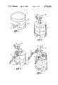
- FIG. 1shows a perspective view of a robot transporter
- FIG. 2shows a perspective view of the robot transporter like FIG. 1 with sensors and an elevating television camera;
- FIG. 3shows a perspective view similar to FIG. 2 with the addition of a single robotic arm
- FIG. 4shows a perspective view of the robotic transporter like FIG. 1 with two robotic arms and a television camera;
- FIG. 5shows a plan view of the lower base assembly
- FIG. 6shows a rear elevation view of FIG. 5
- FIG. 7shows a side elevation view of FIG. 5
- FIG. 8shows a top plan view of the cable management system
- FIG. 9shows a section view of FIG. 8 taken along section 9--9;
- FIG. 10shows a section view of FIG. 8 taken along section 10--10;
- FIG. 11shows a section view of FIG. 8 along section 11--11;
- FIG. 12shows details of the sheave and roller chain tensioner as seen from a bottom view of FIG. 10;
- FIG. 13shows a perspective view of the robot transporter housed in a containment box adjacent a computer system control console arranged for use in a labrynth entrance to a radioactive area;
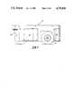
- FIG. 14shows a side view of a containment box with the door open and ramp in place
- FIG. 15shows a view similar to FIG. 14 with the door closed and ramp in stored position on the inside of the door;
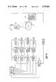
- FIG. 16shows the schematic of a control system for the drive wheels and cable management system of the robot transporter.
- FIGS. 1 through 4there is shown a family of robots based on the present invention.
- a robot transporter version 30 of the mobile robothas a lower base assembly 31, a reel assembly 32 and a rim 36 to keep objects being transported from falling off the unit as it moves.
- the lower base assemblyis supported by two drive wheels 34 and one swivel wheel 35.
- FIG. 2is a modification of FIG. 1 showing an upper base assembly 33 which contains a series of sensors 37, a television camera 38 and two lights 39 for the camera.
- the camerais on an elevating mount 40 which is readily available from commercial sources and is preferably of a type formed from three high strength steel tapes originally used to deploy space satellite antennas.
- FIG. 3is shown another version of the mobile robot which is based on a modification of the one shown in FIG. 2 and has a robotic arm which is like that commercially available from Remote Technology Corporation, 114 Union Valley Road, Oak Ridge, Tenn. 37830. The arm can be folded back on itself so as to not extend beyond the periphery of the circular shape of the robot.
- FIG. 4is another embodiment of the mobile robot which has two of the standard available robotic arms in addition to a television camera 38 and lights 39.
- each of the drive wheels 34are mounted in drive wheel bearing assemblies having an inboard wheel drive gear 44 meshing with a motor output gear 43 driven by a variable speed reversible electric geared wheel drive motor 42. Also coupled to the drive motor through encoder drive gear 46 is an optical encoder 45.
- the lower base assemblycontains six batteries 47 for powering the mobile robot. Preferably, the batteries are Globe Gel/Cell 99 F1807 available from Newark Electronics, 6500 Papermill Road, Knoxville, Tenn. 37919.
- the robotis supported by a third swivel wheel 35 carried in swivel bracket 49. Surrounding the periphery of the robot are several access covers 50 and a metal enclosing skirt 51.
- the reel assemblywhich has a reel frame 52 and a joinder ring 53 for joining to the lower base assembly.
- the reel mounting plate 54is carried by the reel frame and it includes a roller bearing assembly 55 offset from the center of the reel frame. Roller bearing assembly is carried in a bearing retainer 56 affixed to the reel mounting plate. Carried by the roller bearing is a reel stub shaft 58 that is rotatingly mounted but fixed from up and down movement. Carried by the reel stub shaft 58 at its lower end is reel 57 and at its upper end cable sprocket 59. Through a series of standoff posts 60 and reel screws 63 there is a cable retainer mount 61 defining the bottom side of the reel.
- the reel 57is surrounded by a cable skirt 64 which extends most of the periphery around the reel except for that part of the periphery not shown in the drawing where the cable exits to be dispensed from the reel assembly above the swivel wheel.
- the cable skirthas a sufficient clearance from the reel 57 to permit the reel's rotation, but at the same time the clearance is so small as to prevent the cable from falling through the clearance annulus.
- the inboard end of the cablehas a cord grip 65a affixing it in position so that it can rotate with the reel through a slip ring capsule 66.
- the fixed part of the slip ring 66leads the power and communication cables to the proper places within the mobile robot.
- the reelis free to rotate as it dispenses and retracts the cable without it being twisted.
- the cable sprocket 59is driven by roller chains 69 by reel planetary gear motor 70 mounted on reel drive motor mount 71.
- reel planetary gear motor 70mounted on reel drive motor mount 71.
- slip ring anti-rotate bracket 67In order to prevent the slip ring capsule 66 from rotating, there is provide slip ring anti-rotate bracket 67.
- Reel planetary gear motor 70is operatively connected to the reel drive potentiometer encoder 73 mounted on reel drive encoder mount 72. Also shown in FIG. 8 is cable drive planetary gear motor 77 mounted on cable drive motor mount 76 and operatively associated through meshed gears to continuously rotating cabled drive potentiometer encoder 75 mounted on cable drive encoder mount 74.
- FIG. 10which is a cross-section along section 10--10 of FIG. 8, and to FIG. 12 there is shown a cable feed assembly 79.
- the cable drive planetary gear motor 77drives a spur gear 81 through multijar coupler 80.
- Spur gear 81intermeshes with spur gear 82 attached to cable drive potentiometer encoder through coupler 83.
- the cable drive planetary gear motor 77also drives iron groove pulley or sheave 85 which is mounted on a shaft carried by flanged bearing 84.
- the sheavehas a groove 90 in which cable 65 frictionally is carried.
- friction force roller 86made preferably of nylon which is carried at the end of roller chain tensioner arm 89 that is under approximately twenty-two pounds tension created by roller chain tensioner 88, a readily available commercial item.
- the nylon friction force roller 86has two flanges 87 which are spaced wider than the sheave 85 to assist in keeping cable 65 from riding off the face of the roller. It is to be noted that sheave 85 has a sheave groove 90 which is of less depth than the diameter of the cable 65.
- FIG. 11is a sectional view of section 11--11 taken on FIG. 8, there is shown the reel planetary gear motor 70 and encoder 73.
- the gear motor 70carries a sprocket 91 for driving the roller chain 69.
- a spur gear 92meshing with spur gear 93 to drive reel drive potentiometer encoder 73 through coupling 94.
- Robot 95is contained in a containment box 96 which has skids 97 adapted to receive a fork lift or similar lifting arrangement for transporting the box with robot to another location. It has a ramp 98 that permits the robot to ingress and egress into the box under its own power.
- the robot cable 65is not shown in FIG. 13 but runs from the robot to the interior of the box.
- the cablecarries power and serves as a communication link between the console and the robot through the intermediate containment box.
- the cableis attached to the box at a removable panel 101 which can be removed for a fast charge of the robot in its box as opposed to the normal trickel charge.
- the robotis disposed so as to be able to enter the controlled radiation area 102 of a nuclear power plant.
- the areahas a small dam 103 for containing any liquids in the controlled area and a labyrinth entrance 104 having two right angle turns.
- three obstacles 105are shown as representative of the type of conditions that would be met in which the robot would have to maneuver around in order to make its inspection and surveillance.
- the robotIn order to negotiate in such a a controlled area it is necessary that the robot be able to maneuver in a space approximately its own size and must lay down the cable on its trip out with zero tension between the robot and the containment box else the cable could pull up under various objects and otherwise get entangled.
- the robotwhen the robot returns to the containment box, it executes a reversal of it outbound path although provisions can be made for the robot in some cases to return directly to its box if there are no obstacles in its way. If that is done, the cable must be retracted on a manual basis using the television camera on the robot to determine the amount of slack in the system.
- the consoleis used for remote control and for monitoring the sensors and television camera located on the robot.
- the consoleis not part of this invention and would be varied with different locations. It is merely shown as representative of a type that could be used.
- FIG. 14shows a side view of the box with the door 106 open and a broken-away section to show the removable floor 107 and the removable ramp 98 in place so that the raised side guides of the ramp, which are slightly wider than the width of the drive wheels of the robot, are terminated at the forward and upward edge by two hooks 108 which extend through openings in the floor 107 to hold the ramp temporarily in place.
- the two side guides of the rampkeep the robot from falling off the edge of the ramp when it makes its ingress and egress from the box.
- the removable flooralso has two side guides which in addition to helping guide the robot serve to stiffen the floor which is loosely layed in place on brackets stemming around the inside of the box.
- the containment box 96has an access cover plate 101 to permit removal and fast recharging of the batteries of the robot when it is in the box and such fast recharging is desired.
- the boxis mounted on skids 97 which provide openings that can receive a fork lift arrangement such as a low boy to move the portable box from one location to another.
- the ramp 98is lifted from the position of FIG. 14 and stored on the inside of the closed door on bracket 109.
- the inside of the boxhas stiffeners to reinforce it and rubber or foam horizontal ribs of a size that the robot, when in the box with the door closed, will snuggly fit to prevent movement within the box when being transported to a new location.
- the dooris closed and locked with sufficient tightness so that when the containment box with the robot and ramp is on the inside and it is moved from one location to another, none of the contamination is distributed to other areas.
- the main contamination in the boxis that left by the wheels of the robot on the ramp and removable floor. This can be eliminated by removing the floor 107 and ramp 98 and either decontaminating them or throwing them away and replacing them with new ones.
- the connector from the inside of the box to the robotis not shown, but it is in the vicinity on the inside of cover plate 101 so that as the robot egresses from the box and dispenses its cable, it remains connected to the console through the cable leading to the inside of the box.
- the left and right drive motors 42 for the drive wheelsare identical and are connected to identical motor amplifiers 110 which are standard commercial motor amplifiers available from Copley Controls Company, 375 Elliott Street, Newton, Mass. 02164, as their motor amplifier No. 215.
- the drive motors 42are TRW 102A939-9-BL available from TRW Globe Motors, 2275 Stanley Avenue, Dayton, Ohio 45404.
- Each drive motoralso drives identical quadrature-phase optical encoder 45 which is PMI part B-25-0500-AB-5-0 available from PMI Motors, Kellmargen Corp, Syosset, N.Y. 11791.
- the encoder 45is in effect a position indicator for the drive wheel and feeds back through the control system to serve to indicate the movement of the robot as earlier indicated.
- reel drive motor 70 and cable drive motor 77are actuated by motor amplifiers 68 and 78, respectively and serve to drive encoders 73 and 75, respectively, for indicating their position and direction and rate of movement.
- the reel drive motor 70 and cable drive motor 77are available from TRW Globe Motors as planetary gear motor 409A6186-3.
- the motor amplifiers 68 and 78are likewise identical and are available from Copley Controls Corporation as their Servo Amplifier No. 201.
- the encoders 73 and 75are the same and are available from Bourns, Inc., 1200 Columbia Avenue, Riverside, Calif. 92507, as potentiometer 84A1A-B28-J13 (5 Kohms).
- the control system for the robotis at the console where the operator actuates the control such as a joy stick to indicate the direction the robot should go and its speed. Top speed is usually one mile per hour. Using well known servo principles, the control system thus directs the movement of the robot in a well known manner both as to speed and direction.
- the drive wheel encoders 45then indicate information that determines the dispensing and retraction of the cable in a controlled manner so that the cable will not have any tension on it between the robot and its station.
- the stationis usually the containment box, but may be the control console or some other stationing point.
- the remote control and supplying of poweris from the console 100 which is connected through the reel 57, carried by the mobile robot by cable 65.
- the cable 65is connected through a slip ring assembly 66 to any local control system (not part of this invention), power supply, and battery pack all carried on the robot.
- the battery packsupplies the power to the various motor amplifiers as well as on-board control system.
Landscapes
- Engineering & Computer Science (AREA)
- Robotics (AREA)
- Mechanical Engineering (AREA)
- Physics & Mathematics (AREA)
- General Engineering & Computer Science (AREA)
- High Energy & Nuclear Physics (AREA)
- Aviation & Aerospace Engineering (AREA)
- Radar, Positioning & Navigation (AREA)
- Remote Sensing (AREA)
- General Physics & Mathematics (AREA)
- Automation & Control Theory (AREA)
- Manipulator (AREA)
Abstract
Description
Claims (14)
Priority Applications (1)
| Application Number | Priority Date | Filing Date | Title |
|---|---|---|---|
| US06/726,012US4736826A (en) | 1985-04-22 | 1985-04-22 | Remotely controlled and/or powered mobile robot with cable management arrangement |
Applications Claiming Priority (1)
| Application Number | Priority Date | Filing Date | Title |
|---|---|---|---|
| US06/726,012US4736826A (en) | 1985-04-22 | 1985-04-22 | Remotely controlled and/or powered mobile robot with cable management arrangement |
Publications (1)
| Publication Number | Publication Date |
|---|---|
| US4736826Atrue US4736826A (en) | 1988-04-12 |
Family
ID=24916854
Family Applications (1)
| Application Number | Title | Priority Date | Filing Date |
|---|---|---|---|
| US06/726,012Expired - Fee RelatedUS4736826A (en) | 1985-04-22 | 1985-04-22 | Remotely controlled and/or powered mobile robot with cable management arrangement |
Country Status (1)
| Country | Link |
|---|---|
| US (1) | US4736826A (en) |
Cited By (139)
| Publication number | Priority date | Publication date | Assignee | Title |
|---|---|---|---|---|
| DE3840758A1 (en)* | 1988-12-03 | 1990-06-07 | Thomas Hofbauer | Apparatus for combating criminals |
| US5100138A (en)* | 1990-07-18 | 1992-03-31 | Wilde Mark S | Motorized mobile boxing robot |
| US5142803A (en)* | 1989-09-20 | 1992-09-01 | Semborg-Recrob, Corp. | Animated character system with real-time contol |
| US5182557A (en)* | 1989-09-20 | 1993-01-26 | Semborg Recrob, Corp. | Motorized joystick |
| US5198893A (en)* | 1989-09-20 | 1993-03-30 | Semborg Recrob, Corp. | Interactive animated charater immediately after the title |
| US5327354A (en)* | 1990-07-10 | 1994-07-05 | Daifuku Co., Ltd. | Control system for automatic warehousing facility |
| US5432416A (en)* | 1992-09-30 | 1995-07-11 | Samsung Electronics Co., Ltd. | Driving apparatus for robot |
| US5485973A (en)* | 1993-02-05 | 1996-01-23 | Benthos, Inc. | Storage of cable |
| US5495995A (en)* | 1994-01-31 | 1996-03-05 | Reelcraft Industries, Inc. | Motor driven hose reel |
| US5502358A (en)* | 1993-09-01 | 1996-03-26 | Samsung Electronics Co., Ltd. | Method and apparatus for controlling the tension of a power cord of a self-propelled robot |
| US5551545A (en)* | 1994-03-18 | 1996-09-03 | Gelfman; Stanley | Automatic deployment and retrieval tethering system |
| US5554914A (en)* | 1991-11-05 | 1996-09-10 | Miyazawa; Osamu | Micro robot |
| US5596255A (en)* | 1993-06-07 | 1997-01-21 | Seiko Epson Corporation | Method of and apparatus for guiding microrobot |
| US5647554A (en)* | 1990-01-23 | 1997-07-15 | Sanyo Electric Co., Ltd. | Electric working apparatus supplied with electric power through power supply cord |
| US5655945A (en)* | 1992-10-19 | 1997-08-12 | Microsoft Corporation | Video and radio controlled moving and talking device |
| WO1997039505A1 (en)* | 1996-04-12 | 1997-10-23 | Georg Fischer Disa A/S | Energy-transfer connection for a robot |
| US5720077A (en)* | 1994-05-30 | 1998-02-24 | Minolta Co., Ltd. | Running robot carrying out prescribed work using working member and method of working using the same |
| US5845540A (en)* | 1995-06-30 | 1998-12-08 | Ross-Hime Designs, Incorporated | Robotic manipulator |
| US5967580A (en)* | 1995-06-30 | 1999-10-19 | Ross-Hine Designs, Incorporated | Robotic manipulator |
| GB2345051A (en)* | 1998-12-22 | 2000-06-28 | Maria Varvarides | Robot Device |
| RU2163189C1 (en)* | 1999-12-07 | 2001-02-20 | Акинфиев Теодор Самуилович | Device for automatic process treatment of parts |
| US6386906B1 (en) | 1998-03-16 | 2002-05-14 | Telefonix Inc | Cord management apparatus and method |
| US20020058862A1 (en)* | 2000-11-10 | 2002-05-16 | Furnas Steven J. | Method and apparatus for diagnosing pathogenic or allergenic microorganisms or microparticles at a remote location |
| WO2002045915A1 (en)* | 2000-12-04 | 2002-06-13 | Abb Ab | Robot system |
| US6505098B1 (en)* | 1999-10-29 | 2003-01-07 | Sony Corporation | Robot system, robot device, and its cover |
| US6507773B2 (en)* | 2001-06-14 | 2003-01-14 | Sharper Image Corporation | Multi-functional robot with remote and video system |
| US6548982B1 (en)* | 1999-11-19 | 2003-04-15 | Regents Of The University Of Minnesota | Miniature robotic vehicles and methods of controlling same |
| US20040000439A1 (en)* | 2002-04-19 | 2004-01-01 | Burt Ian T. | Adjustable diameter wheel assembly, and methods and vehicles using same |
| US20040010344A1 (en)* | 2002-07-15 | 2004-01-15 | Kawasaki Jukogyo Kabushiki Kaisha | Remote control method and system for robot controller |
| US6690277B1 (en) | 2000-03-24 | 2004-02-10 | Henry Louis Hansen | Security system |
| US6702077B2 (en) | 2000-02-03 | 2004-03-09 | Restech, Inc. | Nested cables and reel assembly |
| US20040143951A1 (en)* | 2002-12-16 | 2004-07-29 | Alwin Berninger | Method and device for positioning components to be joined together |
| US20040200919A1 (en)* | 2003-04-11 | 2004-10-14 | Burke Paul C | Retractable cord reels for use with flat electrical cable |
| US20040254678A1 (en)* | 2003-06-11 | 2004-12-16 | International Business Machines Corporation | Method and apparatus for the exchange of batteries in a robot located in an automated library |
| US20040256064A1 (en)* | 2003-06-19 | 2004-12-23 | Bennett Thomas B. | Sectional door cable tensioner |
| US20050038564A1 (en)* | 2003-08-12 | 2005-02-17 | Burick Thomas J. | Robot with removable mounting elements |
| US20050192185A1 (en)* | 2004-02-27 | 2005-09-01 | Saathoff Lee D. | Power transmission fluids |
| US20060009876A1 (en)* | 2004-06-09 | 2006-01-12 | Mcneil Dean | Guidance system for a robot |
| US20060020369A1 (en)* | 2004-03-11 | 2006-01-26 | Taylor Charles E | Robot vacuum cleaner |
| US20060076745A1 (en)* | 2004-10-12 | 2006-04-13 | Gordon Gary B | Camera dolly |
| DE102004058892A1 (en)* | 2004-11-29 | 2006-06-01 | Hochschule für Technik und Wirtschaft Dresden (FH) | Robot system for use in e.g. office, has layer modules and columnar connecting modules, where layer modules are arranged in the layers which comprise of provided orientation and remains in connection with connection modules |
| US20070025555A1 (en)* | 2005-07-28 | 2007-02-01 | Fujitsu Limited | Method and apparatus for processing information, and computer product |
| US20070084978A1 (en)* | 2005-10-17 | 2007-04-19 | Martin Randall W | Multiple-display mount |
| US20070086153A1 (en)* | 2005-10-17 | 2007-04-19 | Martin Randall W | Display base cable management system and method |
| US20070084624A1 (en)* | 2005-10-17 | 2007-04-19 | Martin Randall W | System and method for managing cables in a display base |
| US20070084625A1 (en)* | 2005-10-17 | 2007-04-19 | Martin Randall W | System and method for managing cables in a display stand |
| CN1319702C (en)* | 2003-10-29 | 2007-06-06 | 中国科学院自动化研究所 | Movable manipulator system |
| US20070138360A1 (en)* | 2005-10-17 | 2007-06-21 | Martin Randall W | System for mounting devices to a display |
| US20070146480A1 (en)* | 2005-12-22 | 2007-06-28 | Judge John J Jr | Apparatus and method for inspecting areas surrounding nuclear boiling water reactor core and annulus regions |
| FR2896584A1 (en)* | 2006-01-23 | 2007-07-27 | Igeb France Sarl | INSTALLATION FOR THE INSPECTION AND / OR INTERVENTION IN A MASS OF PULVERULENT OR GRANULAR MATERIAL STORED IN BULK |
| US7266421B1 (en)* | 1998-11-10 | 2007-09-04 | Commissariat A L'energie Atomique | System for controlling lifting and remote handling units located in a confined enclosure |
| US20070252360A1 (en)* | 2005-01-24 | 2007-11-01 | Wooten Donald W | Trailer hitch assembly |
| US20070267230A1 (en)* | 1998-03-27 | 2007-11-22 | Irobot Corporation | Robotic Platform |
| CN100361792C (en)* | 2004-09-10 | 2008-01-16 | 中国科学院自动化研究所 | A mobile manipulator control system |
| US20080028880A1 (en)* | 2006-08-01 | 2008-02-07 | Asada H Harry | Gravity driven underactuated robot arm for assembly operations inside an aircraft wing box |
| US7331436B1 (en) | 2003-03-26 | 2008-02-19 | Irobot Corporation | Communications spooler for a mobile robot |
| US20080042620A1 (en)* | 2006-08-16 | 2008-02-21 | Honda Motor Co., Ltd. | Battery Charger |
| US20080167752A1 (en)* | 2006-11-13 | 2008-07-10 | Jacobsen Stephen C | Tracked robotic crawler having a moveable arm |
| US20080215185A1 (en)* | 2006-11-13 | 2008-09-04 | Jacobsen Stephen C | Unmanned ground robotic vehicle having an alternatively extendible and retractable sensing appendage |
| US20080217993A1 (en)* | 2006-11-13 | 2008-09-11 | Jacobsen Stephen C | Conformable track assembly for a robotic crawler |
| US20080230285A1 (en)* | 2006-12-06 | 2008-09-25 | The Regents Of The University Of California | Multimodal agile robots |
| US20080236858A1 (en)* | 2007-03-27 | 2008-10-02 | David Quijano | Cable management system |
| US7459634B2 (en) | 2005-10-17 | 2008-12-02 | Hewlett-Packard Development Company, L.P. | System and method for managing cables |
| US20090025371A1 (en)* | 2007-06-19 | 2009-01-29 | Jonas Hermansson | Control of an Exhaust Gas Aftertreatment Device in a Hybrid Vehicle |
| US20090030562A1 (en)* | 2007-07-10 | 2009-01-29 | Jacobsen Stephen C | Modular Robotic Crawler |
| US20090149995A1 (en)* | 2007-12-06 | 2009-06-11 | Honda Motor Co., Ltd. | Charging apparatus for mobile robot |
| US7555581B2 (en) | 2005-10-17 | 2009-06-30 | Hewlett-Packard Development Company, L.P. | Communications display base system and method |
| US7559385B1 (en) | 2004-03-10 | 2009-07-14 | Regents Of The University Of Minnesota | Ruggedized robotic vehicles |
| US20100076598A1 (en)* | 2008-05-08 | 2010-03-25 | Herbert Sammuel D | Robotic vehicle system |
| US20100126403A1 (en)* | 2008-11-21 | 2010-05-27 | Rooney Iii James H | Hull Robot |
| US20100131098A1 (en)* | 2008-11-21 | 2010-05-27 | Rooney Iii James H | Hull robot with rotatable turret |
| US20100174422A1 (en)* | 2009-01-08 | 2010-07-08 | Jacobsen Stephen C | Point And Go Navigation System And Method |
| US20100219003A1 (en)* | 2008-11-21 | 2010-09-02 | Rooney Iii James H | Hull robot steering system |
| US7805220B2 (en) | 2003-03-14 | 2010-09-28 | Sharper Image Acquisition Llc | Robot vacuum with internal mapping system |
| US20100258365A1 (en)* | 2006-11-13 | 2010-10-14 | Raytheon Sarcos, Llc | Serpentine Robotic Crawler |
| US20100318242A1 (en)* | 2009-06-11 | 2010-12-16 | Jacobsen Stephen C | Method And System For Deploying A Surveillance Network |
| US20110035054A1 (en)* | 2007-08-08 | 2011-02-10 | Wave Group Ltd. | System for Extending The Observation, Surveillance, and Navigational Capabilities of a Robot |
| US20110046781A1 (en)* | 2009-08-21 | 2011-02-24 | Harris Corporation, Corporation Of The State Of Delaware | Coordinated action robotic system and related methods |
| US20110067615A1 (en)* | 2009-09-18 | 2011-03-24 | Rooney Iii James H | Hull robot garage |
| US20110083599A1 (en)* | 2009-10-14 | 2011-04-14 | Kornstein Howard R | Hull robot drive system |
| US20110133013A1 (en)* | 2008-08-05 | 2011-06-09 | Koninklijke Philips Electronics N.V. | Paying out and retracting an electric power cord |
| US8005571B2 (en) | 2002-08-13 | 2011-08-23 | Neuroarm Surgical Ltd. | Microsurgical robot system |
| US8002716B2 (en) | 2007-05-07 | 2011-08-23 | Raytheon Company | Method for manufacturing a complex structure |
| US8317555B2 (en) | 2009-06-11 | 2012-11-27 | Raytheon Company | Amphibious robotic crawler |
| WO2012129251A3 (en)* | 2011-03-23 | 2012-12-20 | Sri International | Dexterous telemanipulator system |
| US8386112B2 (en) | 2010-05-17 | 2013-02-26 | Raytheon Company | Vessel hull robot navigation subsystem |
| US8393422B1 (en) | 2012-05-25 | 2013-03-12 | Raytheon Company | Serpentine robotic crawler |
| CN103112002A (en)* | 2013-01-23 | 2013-05-22 | 南宁燎旺车灯有限责任公司 | Intelligent movable mechanical hand |
| CN103707301A (en)* | 2012-10-08 | 2014-04-09 | 张婧怡 | Thief catching robot hand |
| CN103737590A (en)* | 2014-01-24 | 2014-04-23 | 成都万先自动化科技有限责任公司 | Company work conveying service robot |
| EP2757536A1 (en)* | 2013-01-17 | 2014-07-23 | Wincor Nixdorf International GmbH | Device for the autonomous transport of cash boxes between the till area and the back office |
| CN103963043A (en)* | 2014-04-30 | 2014-08-06 | 湖南大学 | Intelligent robot for power station inspection and maintenance and control system thereof |
| CN104002303A (en)* | 2014-06-09 | 2014-08-27 | 国网上海市电力公司 | Robot of six degrees of freedom for loading and unloading of automatic transformer verification flow line |
| EP2804181A1 (en) | 2013-05-15 | 2014-11-19 | ECA Robotics | Device for monitoring and collecting information in an area with a potential risk of irradiation |
| US20140360832A1 (en)* | 2013-06-06 | 2014-12-11 | Brett Aldrich | Apparatus and method for providing tethered electrical power to autonomous mobile robots |
| US9020639B2 (en) | 2009-08-06 | 2015-04-28 | The Regents Of The University Of California | Multimodal dynamic robotic systems |
| US9031698B2 (en) | 2012-10-31 | 2015-05-12 | Sarcos Lc | Serpentine robotic crawler |
| US9038557B2 (en) | 2012-09-14 | 2015-05-26 | Raytheon Company | Hull robot with hull separation countermeasures |
| US20150253129A1 (en)* | 2014-03-06 | 2015-09-10 | Omron Corporation | Inspection apparatus |
| WO2015144828A1 (en)* | 2014-03-26 | 2015-10-01 | Isec Industrial Security Ab | Radiation tolerant cable reel |
| US9409292B2 (en) | 2013-09-13 | 2016-08-09 | Sarcos Lc | Serpentine robotic crawler for performing dexterous operations |
| CN105922272A (en)* | 2016-06-03 | 2016-09-07 | 深圳市中幼国际教育科技有限公司 | Child accompanying robot |
| CN106003089A (en)* | 2016-07-03 | 2016-10-12 | 深圳市中幼国际教育科技有限公司 | Intelligent partner robot for children |
| CN106363612A (en)* | 2016-10-18 | 2017-02-01 | 南京航空航天大学 | Visual guidance type omnidirectional mobile double-arm robot and omnidirectional moving method thereof |
| US9566711B2 (en) | 2014-03-04 | 2017-02-14 | Sarcos Lc | Coordinated robotic control |
| CN106475993A (en)* | 2016-11-21 | 2017-03-08 | 徐州云行自动化科技有限公司 | A kind of indoor positioning information gathering machine people |
| CN108840052A (en)* | 2018-06-22 | 2018-11-20 | 中国科学院光电技术研究所 | Hot chamber radioactive workpiece transfer system |
| WO2018163142A3 (en)* | 2018-05-22 | 2018-11-22 | Tinkerall | Modular vending machine in stackable units |
| CN109202885A (en)* | 2017-06-30 | 2019-01-15 | 沈阳新松机器人自动化股份有限公司 | A kind of mobile composite machine people of material carrying |
| CN109249401A (en)* | 2018-08-15 | 2019-01-22 | 北京思迈特科技有限公司 | A kind of the cable duct crusing robot and its implementation of high obstacle climbing ability |
| US10189342B2 (en) | 2015-02-09 | 2019-01-29 | The Regents Of The University Of California | Ball-balancing robot and drive assembly therefor |
| US20190033691A1 (en)* | 2016-04-20 | 2019-01-31 | Guangdong Sirui Optical Co., Ltd. | Camera dolly, remote-controlled camera dolly system and camera dolly photographing control method |
| CN109473192A (en)* | 2018-12-26 | 2019-03-15 | 山西医科大学第医院 | Mobile radiation protection equipment |
| CN109822543A (en)* | 2019-03-28 | 2019-05-31 | 创泽智能机器人股份有限公司 | A kind of positioning navigation device based on robot ambulation |
| CN109865770A (en)* | 2017-12-01 | 2019-06-11 | 中国科学院沈阳自动化研究所扬州工程技术研究中心 | A kind of mechanical press system based on tow-armed robot |
| US10418863B1 (en)* | 2015-09-28 | 2019-09-17 | Apple Inc. | Charging system |
| US20190304271A1 (en)* | 2018-04-03 | 2019-10-03 | Chengfu Yu | Smart tracker ip camera device and method |
| CN110405717A (en)* | 2019-07-27 | 2019-11-05 | 南京昱晟机器人科技有限公司 | An industrial robot universal walking mechanism and method |
| US10526029B2 (en) | 2017-08-15 | 2020-01-07 | Reconrobotics, Inc. | Two wheeled robot with convertibility and accessories |
| FR3084025A1 (en)* | 2018-07-19 | 2020-01-24 | Psa Automobiles Sa | AUTONOMOUS MOBILE HOUSING WITH ILLUMINATION OF ITS SURROUNDINGS, FOR INDUCILY CHARGING A VEHICLE BATTERY |
| US10589430B2 (en) | 2017-08-15 | 2020-03-17 | Reconrobotics, Inc. | Throwable robot with improved drive system |
| JP2020091213A (en)* | 2018-12-06 | 2020-06-11 | 日立Geニュークリア・エナジー株式会社 | Surface contamination density measurement system |
| US10695686B2 (en) | 2013-09-27 | 2020-06-30 | Innovation First, Inc. | Mechanical spinning robot toy |
| US20200239266A1 (en)* | 2019-01-29 | 2020-07-30 | Brett Aldrich | Apparatus and method for providing tethered electrical power to autonomous unmanned ground vehicles |
| US10969296B2 (en)* | 2018-11-19 | 2021-04-06 | General Electric Company | Leak-detection systems including inspection vehicles and leak-detection devices |
| US10987818B2 (en) | 2017-08-15 | 2021-04-27 | Reconrobotics, Inc. | Magnetic lock for throwable robot |
| CN113165162A (en)* | 2018-12-03 | 2021-07-23 | Groove X 株式会社 | Charging station for robot |
| US20220016758A1 (en)* | 2020-07-14 | 2022-01-20 | Vicarious Fpc, Inc. | Method and system for monitoring a container fullness |
| WO2022085634A1 (en)* | 2020-10-21 | 2022-04-28 | ファナック株式会社 | Control device, control system, program, and control method |
| CN114655787A (en)* | 2022-04-26 | 2022-06-24 | 上海伯镭智能科技有限公司 | Intelligent cable reel trolley for open pit mine |
| CN114700923A (en)* | 2022-04-28 | 2022-07-05 | 青岛都利智能科技有限公司 | Multifunctional manipulator |
| US20220331945A1 (en)* | 2021-04-20 | 2022-10-20 | Gecko Robotics, Inc. | Inspection robots with flexible wheel/motor positioning |
| US11479102B2 (en) | 2017-08-15 | 2022-10-25 | Reconrobotics, Inc. | Two wheel robot with convertibility and accessories |
| US11623339B1 (en)* | 2019-05-16 | 2023-04-11 | Amazon Technologies, Inc. | Portable robotic manipulation systems |
| CN118832607A (en)* | 2024-08-14 | 2024-10-25 | 北京朋正华兴光电科技有限公司 | Explosive-handling robot |
| US12194824B2 (en) | 2017-08-15 | 2025-01-14 | Reconrobotics, Inc. | Two wheel robot with convertibility and accessories |
| US12228550B2 (en) | 2021-04-22 | 2025-02-18 | Gecko Robotics, Inc. | Robotic systems for ultrasonic surface inspection using shaped elements |
| US12311550B2 (en) | 2020-12-31 | 2025-05-27 | Sarcos Corp. | Smart control system for a robotic device |
| US12358141B2 (en) | 2016-12-23 | 2025-07-15 | Gecko Robotics, Inc. | Systems, methods, and apparatus for providing interactive inspection map for inspection robot |
Citations (5)
| Publication number | Priority date | Publication date | Assignee | Title |
|---|---|---|---|---|
| US3632906A (en)* | 1970-09-14 | 1972-01-04 | Caterpillar Mitsubishi Ltd | Cable winder on tractor |
| US4010346A (en)* | 1975-04-14 | 1977-03-01 | Cecil Equipment Co., Inc. | Self-propelled tractor for welding and cutting apparatus and the like |
| US4046262A (en)* | 1974-01-24 | 1977-09-06 | The United States Of America As Represented By The Administrator Of The National Aeronautics And Space Administration | Anthropomorphic master/slave manipulator system |
| JPS59214917A (en)* | 1983-05-21 | 1984-12-04 | Toshiba Corp | Checking and monitoring device |
| US4511100A (en)* | 1982-03-13 | 1985-04-16 | M.A.N. Maschinenfabrik Aktiengesellschaft | Railless vechicle for underground mining |
- 1985
- 1985-04-22USUS06/726,012patent/US4736826A/ennot_activeExpired - Fee Related
Patent Citations (5)
| Publication number | Priority date | Publication date | Assignee | Title |
|---|---|---|---|---|
| US3632906A (en)* | 1970-09-14 | 1972-01-04 | Caterpillar Mitsubishi Ltd | Cable winder on tractor |
| US4046262A (en)* | 1974-01-24 | 1977-09-06 | The United States Of America As Represented By The Administrator Of The National Aeronautics And Space Administration | Anthropomorphic master/slave manipulator system |
| US4010346A (en)* | 1975-04-14 | 1977-03-01 | Cecil Equipment Co., Inc. | Self-propelled tractor for welding and cutting apparatus and the like |
| US4511100A (en)* | 1982-03-13 | 1985-04-16 | M.A.N. Maschinenfabrik Aktiengesellschaft | Railless vechicle for underground mining |
| JPS59214917A (en)* | 1983-05-21 | 1984-12-04 | Toshiba Corp | Checking and monitoring device |
Non-Patent Citations (4)
| Title |
|---|
| "Nuclear Power Plant Emergency Control Robot", Robotics Age, Mar./Apr. 1983, pp. 18-21. |
| J. R. White, R. E. Eversole, K. A. Farnstrom, H. W. Harvey, H. L. Martin, "Evaluation of Robotic Inspection Systems at Nuclear Power Plants," Mar. 1984, pp. iii, 1-1, 1-2, 1-3, 2-11, 4-1, 4-2, 4-3, 4-18. |
| J. R. White, R. E. Eversole, K. A. Farnstrom, H. W. Harvey, H. L. Martin, Evaluation of Robotic Inspection Systems at Nuclear Power Plants, Mar. 1984, pp. iii, 1 1, 1 2, 1 3, 2 11, 4 1, 4 2, 4 3, 4 18.* |
| Nuclear Power Plant Emergency Control Robot , Robotics Age, Mar./Apr. 1983, pp. 18 21.* |
Cited By (242)
| Publication number | Priority date | Publication date | Assignee | Title |
|---|---|---|---|---|
| DE3840758A1 (en)* | 1988-12-03 | 1990-06-07 | Thomas Hofbauer | Apparatus for combating criminals |
| US5142803A (en)* | 1989-09-20 | 1992-09-01 | Semborg-Recrob, Corp. | Animated character system with real-time contol |
| US5182557A (en)* | 1989-09-20 | 1993-01-26 | Semborg Recrob, Corp. | Motorized joystick |
| US5198893A (en)* | 1989-09-20 | 1993-03-30 | Semborg Recrob, Corp. | Interactive animated charater immediately after the title |
| US5647554A (en)* | 1990-01-23 | 1997-07-15 | Sanyo Electric Co., Ltd. | Electric working apparatus supplied with electric power through power supply cord |
| US5327354A (en)* | 1990-07-10 | 1994-07-05 | Daifuku Co., Ltd. | Control system for automatic warehousing facility |
| US5100138A (en)* | 1990-07-18 | 1992-03-31 | Wilde Mark S | Motorized mobile boxing robot |
| US5554914A (en)* | 1991-11-05 | 1996-09-10 | Miyazawa; Osamu | Micro robot |
| US5432416A (en)* | 1992-09-30 | 1995-07-11 | Samsung Electronics Co., Ltd. | Driving apparatus for robot |
| US5655945A (en)* | 1992-10-19 | 1997-08-12 | Microsoft Corporation | Video and radio controlled moving and talking device |
| US5485973A (en)* | 1993-02-05 | 1996-01-23 | Benthos, Inc. | Storage of cable |
| US5596255A (en)* | 1993-06-07 | 1997-01-21 | Seiko Epson Corporation | Method of and apparatus for guiding microrobot |
| US5502358A (en)* | 1993-09-01 | 1996-03-26 | Samsung Electronics Co., Ltd. | Method and apparatus for controlling the tension of a power cord of a self-propelled robot |
| US5495995A (en)* | 1994-01-31 | 1996-03-05 | Reelcraft Industries, Inc. | Motor driven hose reel |
| US5551545A (en)* | 1994-03-18 | 1996-09-03 | Gelfman; Stanley | Automatic deployment and retrieval tethering system |
| US5720077A (en)* | 1994-05-30 | 1998-02-24 | Minolta Co., Ltd. | Running robot carrying out prescribed work using working member and method of working using the same |
| US5845540A (en)* | 1995-06-30 | 1998-12-08 | Ross-Hime Designs, Incorporated | Robotic manipulator |
| US5967580A (en)* | 1995-06-30 | 1999-10-19 | Ross-Hine Designs, Incorporated | Robotic manipulator |
| WO1997039505A1 (en)* | 1996-04-12 | 1997-10-23 | Georg Fischer Disa A/S | Energy-transfer connection for a robot |
| US20020189842A1 (en)* | 1998-03-16 | 2002-12-19 | Burke Paul C. | Cord management apparatus and method |
| US6761579B2 (en) | 1998-03-16 | 2004-07-13 | Telefonix, Inc. | Secure mounting assembly for a retail product display |
| US6386906B1 (en) | 1998-03-16 | 2002-05-14 | Telefonix Inc | Cord management apparatus and method |
| US6896543B2 (en) | 1998-03-16 | 2005-05-24 | Telefonix, Inc. | Secure mounting assembly for a retail product display |
| US20040229498A1 (en)* | 1998-03-16 | 2004-11-18 | Fort Calvin L. | Secure mounting assembly for a retail product display |
| US8113304B2 (en) | 1998-03-27 | 2012-02-14 | Irobot Corporation | Robotic platform |
| US7546891B2 (en) | 1998-03-27 | 2009-06-16 | Irobot Corporation | Robotic platform |
| US8365848B2 (en) | 1998-03-27 | 2013-02-05 | Irobot Corporation | Robotic platform |
| US20080143064A1 (en)* | 1998-03-27 | 2008-06-19 | Irobot Corporation | Robotic Platform |
| US20070267230A1 (en)* | 1998-03-27 | 2007-11-22 | Irobot Corporation | Robotic Platform |
| US7597162B2 (en) | 1998-03-27 | 2009-10-06 | Irobot Corporation | Robotic platform |
| US7556108B2 (en) | 1998-03-27 | 2009-07-07 | Irobot Corporation | Robotic platform |
| US8763732B2 (en) | 1998-03-27 | 2014-07-01 | Irobot Corporation | Robotic platform |
| US20090107738A1 (en)* | 1998-03-27 | 2009-04-30 | Irobot Corporation | Robotic Platform |
| US9573638B2 (en) | 1998-03-27 | 2017-02-21 | Irobot Defense Holdings, Inc. | Robotic platform |
| US9248874B2 (en) | 1998-03-27 | 2016-02-02 | Irobot Corporation | Robotic platform |
| US20080236907A1 (en)* | 1998-03-27 | 2008-10-02 | Irobot Corporation | Robotic Platform |
| US7266421B1 (en)* | 1998-11-10 | 2007-09-04 | Commissariat A L'energie Atomique | System for controlling lifting and remote handling units located in a confined enclosure |
| GB2345051A (en)* | 1998-12-22 | 2000-06-28 | Maria Varvarides | Robot Device |
| US6505098B1 (en)* | 1999-10-29 | 2003-01-07 | Sony Corporation | Robot system, robot device, and its cover |
| US6711469B2 (en) | 1999-10-29 | 2004-03-23 | Sony Corporation | Robot system, robot apparatus and cover for robot apparatus |
| US6548982B1 (en)* | 1999-11-19 | 2003-04-15 | Regents Of The University Of Minnesota | Miniature robotic vehicles and methods of controlling same |
| RU2163189C1 (en)* | 1999-12-07 | 2001-02-20 | Акинфиев Теодор Самуилович | Device for automatic process treatment of parts |
| US6702077B2 (en) | 2000-02-03 | 2004-03-09 | Restech, Inc. | Nested cables and reel assembly |
| US6690277B1 (en) | 2000-03-24 | 2004-02-10 | Henry Louis Hansen | Security system |
| US7418118B2 (en)* | 2000-11-10 | 2008-08-26 | Furnas Steven J | Method and apparatus for diagnosing pathogenic or allergenic microorganisms or microparticles at a remote location |
| US20020058862A1 (en)* | 2000-11-10 | 2002-05-16 | Furnas Steven J. | Method and apparatus for diagnosing pathogenic or allergenic microorganisms or microparticles at a remote location |
| US20040093650A1 (en)* | 2000-12-04 | 2004-05-13 | Martins Goesta | Robot system |
| US7066291B2 (en) | 2000-12-04 | 2006-06-27 | Abb Ab | Robot system |
| WO2002045915A1 (en)* | 2000-12-04 | 2002-06-13 | Abb Ab | Robot system |
| US6507773B2 (en)* | 2001-06-14 | 2003-01-14 | Sharper Image Corporation | Multi-functional robot with remote and video system |
| US6865447B2 (en) | 2001-06-14 | 2005-03-08 | Sharper Image Corporation | Robot capable of detecting an edge |
| US6611734B2 (en) | 2001-06-14 | 2003-08-26 | Sharper Image Corporation | Robot capable of gripping objects |
| US6604022B2 (en) | 2001-06-14 | 2003-08-05 | Sharper Image Corporation | Robot for autonomous operation |
| US20040059467A1 (en)* | 2001-06-14 | 2004-03-25 | Sharper Image Corporation | Robot capable of detecting an edge |
| US7024280B2 (en)* | 2001-06-14 | 2006-04-04 | Sharper Image Corporation | Robot capable of detecting an edge |
| US6594551B2 (en) | 2001-06-14 | 2003-07-15 | Sharper Image Corporation | Robot for expressing moods |
| US20050049750A1 (en)* | 2001-06-14 | 2005-03-03 | Sharper Image Corporation | Robot capable of detecting an edge |
| US20040000439A1 (en)* | 2002-04-19 | 2004-01-01 | Burt Ian T. | Adjustable diameter wheel assembly, and methods and vehicles using same |
| US6860346B2 (en) | 2002-04-19 | 2005-03-01 | Regents Of The University Of Minnesota | Adjustable diameter wheel assembly, and methods and vehicles using same |
| US20040010344A1 (en)* | 2002-07-15 | 2004-01-15 | Kawasaki Jukogyo Kabushiki Kaisha | Remote control method and system for robot controller |
| US8041459B2 (en) | 2002-08-13 | 2011-10-18 | Neuroarm Surgical Ltd. | Methods relating to microsurgical robot system |
| US8396598B2 (en) | 2002-08-13 | 2013-03-12 | Neuroarm Surgical Ltd. | Microsurgical robot system |
| US9220567B2 (en) | 2002-08-13 | 2015-12-29 | Neuroarm Surgical Ltd. | Microsurgical robot system |
| US8005571B2 (en) | 2002-08-13 | 2011-08-23 | Neuroarm Surgical Ltd. | Microsurgical robot system |
| US8170717B2 (en) | 2002-08-13 | 2012-05-01 | Neuroarm Surgical Ltd. | Microsurgical robot system |
| US20040143951A1 (en)* | 2002-12-16 | 2004-07-29 | Alwin Berninger | Method and device for positioning components to be joined together |
| US7331094B2 (en)* | 2002-12-16 | 2008-02-19 | Kuka Roboter Gmbh | Method and device for positioning components to be joined together |
| US7805220B2 (en) | 2003-03-14 | 2010-09-28 | Sharper Image Acquisition Llc | Robot vacuum with internal mapping system |
| US8042663B1 (en) | 2003-03-26 | 2011-10-25 | Irobot Corporation | Communications spooler for a mobile robot |
| US7546912B1 (en) | 2003-03-26 | 2009-06-16 | Irobot Corporation | Communications spooler for a mobile robot |
| US8485330B2 (en)* | 2003-03-26 | 2013-07-16 | Irobot Corporation | Communications spooler for a mobile robot |
| US7331436B1 (en) | 2003-03-26 | 2008-02-19 | Irobot Corporation | Communications spooler for a mobile robot |
| US20120097783A1 (en)* | 2003-03-26 | 2012-04-26 | iRobot, a Delaware corporation | Communications spooler for a mobile robot |
| US7108216B2 (en) | 2003-04-11 | 2006-09-19 | Telefonix, Inc. | Retractable cord reels for use with flat electrical cable |
| US20040200919A1 (en)* | 2003-04-11 | 2004-10-14 | Burke Paul C | Retractable cord reels for use with flat electrical cable |
| US6909940B2 (en) | 2003-06-11 | 2005-06-21 | International Business Machines Corporation | Method and apparatus for the exchange of batteries in a robot located in an automated library |
| US20040254678A1 (en)* | 2003-06-11 | 2004-12-16 | International Business Machines Corporation | Method and apparatus for the exchange of batteries in a robot located in an automated library |
| US20040256064A1 (en)* | 2003-06-19 | 2004-12-23 | Bennett Thomas B. | Sectional door cable tensioner |
| US7635017B2 (en) | 2003-06-19 | 2009-12-22 | Wayne-Dalton Corp. | Sectional door cable tensioner |
| US20060027343A1 (en)* | 2003-06-19 | 2006-02-09 | Bennett Thomas B Iii | Sectional door cable tensioner |
| US20050038564A1 (en)* | 2003-08-12 | 2005-02-17 | Burick Thomas J. | Robot with removable mounting elements |
| WO2005018881A3 (en)* | 2003-08-12 | 2006-04-27 | Thomas J Burick | Robot with removable mounting elements |
| US7413040B2 (en) | 2003-08-12 | 2008-08-19 | White Box Robotics, Inc. | Robot with removable mounting elements |
| CN1319702C (en)* | 2003-10-29 | 2007-06-06 | 中国科学院自动化研究所 | Movable manipulator system |
| US20050192185A1 (en)* | 2004-02-27 | 2005-09-01 | Saathoff Lee D. | Power transmission fluids |
| US7559385B1 (en) | 2004-03-10 | 2009-07-14 | Regents Of The University Of Minnesota | Ruggedized robotic vehicles |
| US20060020369A1 (en)* | 2004-03-11 | 2006-01-26 | Taylor Charles E | Robot vacuum cleaner |
| US20060009876A1 (en)* | 2004-06-09 | 2006-01-12 | Mcneil Dean | Guidance system for a robot |
| CN100361792C (en)* | 2004-09-10 | 2008-01-16 | 中国科学院自动化研究所 | A mobile manipulator control system |
| US7802802B2 (en)* | 2004-10-12 | 2010-09-28 | Cambotics Inc. | Camera dolly |
| US20060076745A1 (en)* | 2004-10-12 | 2006-04-13 | Gordon Gary B | Camera dolly |
| DE102004058892A1 (en)* | 2004-11-29 | 2006-06-01 | Hochschule für Technik und Wirtschaft Dresden (FH) | Robot system for use in e.g. office, has layer modules and columnar connecting modules, where layer modules are arranged in the layers which comprise of provided orientation and remains in connection with connection modules |
| US20070252360A1 (en)* | 2005-01-24 | 2007-11-01 | Wooten Donald W | Trailer hitch assembly |
| US20070025555A1 (en)* | 2005-07-28 | 2007-02-01 | Fujitsu Limited | Method and apparatus for processing information, and computer product |
| US7459634B2 (en) | 2005-10-17 | 2008-12-02 | Hewlett-Packard Development Company, L.P. | System and method for managing cables |
| US8033515B2 (en) | 2005-10-17 | 2011-10-11 | Hewlett-Packard Development Company, L.P. | System for mounting devices to a display |
| US7555581B2 (en) | 2005-10-17 | 2009-06-30 | Hewlett-Packard Development Company, L.P. | Communications display base system and method |
| US20070084624A1 (en)* | 2005-10-17 | 2007-04-19 | Martin Randall W | System and method for managing cables in a display base |
| US20070138360A1 (en)* | 2005-10-17 | 2007-06-21 | Martin Randall W | System for mounting devices to a display |
| US20070086153A1 (en)* | 2005-10-17 | 2007-04-19 | Martin Randall W | Display base cable management system and method |
| US20070084978A1 (en)* | 2005-10-17 | 2007-04-19 | Martin Randall W | Multiple-display mount |
| US20070084625A1 (en)* | 2005-10-17 | 2007-04-19 | Martin Randall W | System and method for managing cables in a display stand |
| US7514631B2 (en) | 2005-10-17 | 2009-04-07 | Hewlett-Packard Development Company, L.P. | System and method for managing cables in a display base |
| US20070146480A1 (en)* | 2005-12-22 | 2007-06-28 | Judge John J Jr | Apparatus and method for inspecting areas surrounding nuclear boiling water reactor core and annulus regions |
| WO2007145667A3 (en)* | 2005-12-22 | 2008-03-13 | Exelon Corp | Apparatus and method for inspecting areas surrounding nuclear boiling water reactor core and annulus regions |
| WO2007083043A3 (en)* | 2006-01-23 | 2007-09-07 | Igeb France | Installation for inspection and/or intervention in a mass of bulk-stored powdery or granular material |
| FR2896584A1 (en)* | 2006-01-23 | 2007-07-27 | Igeb France Sarl | INSTALLATION FOR THE INSPECTION AND / OR INTERVENTION IN A MASS OF PULVERULENT OR GRANULAR MATERIAL STORED IN BULK |
| US20080028880A1 (en)* | 2006-08-01 | 2008-02-07 | Asada H Harry | Gravity driven underactuated robot arm for assembly operations inside an aircraft wing box |
| US7825633B2 (en)* | 2006-08-16 | 2010-11-02 | Honda Motor Co., Ltd. | Battery charger |
| US20080042620A1 (en)* | 2006-08-16 | 2008-02-21 | Honda Motor Co., Ltd. | Battery Charger |
| US8002365B2 (en) | 2006-11-13 | 2011-08-23 | Raytheon Company | Conformable track assembly for a robotic crawler |
| US8042630B2 (en) | 2006-11-13 | 2011-10-25 | Raytheon Company | Serpentine robotic crawler |
| US20080217993A1 (en)* | 2006-11-13 | 2008-09-11 | Jacobsen Stephen C | Conformable track assembly for a robotic crawler |
| US20080167752A1 (en)* | 2006-11-13 | 2008-07-10 | Jacobsen Stephen C | Tracked robotic crawler having a moveable arm |
| US20100258365A1 (en)* | 2006-11-13 | 2010-10-14 | Raytheon Sarcos, Llc | Serpentine Robotic Crawler |
| US20080215185A1 (en)* | 2006-11-13 | 2008-09-04 | Jacobsen Stephen C | Unmanned ground robotic vehicle having an alternatively extendible and retractable sensing appendage |
| US8205695B2 (en) | 2006-11-13 | 2012-06-26 | Raytheon Company | Conformable track assembly for a robotic crawler |
| US8185241B2 (en) | 2006-11-13 | 2012-05-22 | Raytheon Company | Tracked robotic crawler having a moveable arm |
| US20100201185A1 (en)* | 2006-11-13 | 2010-08-12 | Raytheon Sarcos, Llc | Conformable Track Assembly For A Robotic Crawler |
| US20080230285A1 (en)* | 2006-12-06 | 2008-09-25 | The Regents Of The University Of California | Multimodal agile robots |
| US8083013B2 (en)* | 2006-12-06 | 2011-12-27 | The Regents Of The University Of California | Multimodal agile robots |
| US7622673B2 (en) | 2007-03-27 | 2009-11-24 | Hewlett-Packard Development Company, L.P. | Cable management system |
| US20080236858A1 (en)* | 2007-03-27 | 2008-10-02 | David Quijano | Cable management system |
| US8434208B2 (en) | 2007-05-07 | 2013-05-07 | Raytheon Company | Two-dimensional layout for use in a complex structure |
| US8002716B2 (en) | 2007-05-07 | 2011-08-23 | Raytheon Company | Method for manufacturing a complex structure |
| US20090025371A1 (en)* | 2007-06-19 | 2009-01-29 | Jonas Hermansson | Control of an Exhaust Gas Aftertreatment Device in a Hybrid Vehicle |
| US8571711B2 (en) | 2007-07-10 | 2013-10-29 | Raytheon Company | Modular robotic crawler |
| US20090030562A1 (en)* | 2007-07-10 | 2009-01-29 | Jacobsen Stephen C | Modular Robotic Crawler |
| US20110035054A1 (en)* | 2007-08-08 | 2011-02-10 | Wave Group Ltd. | System for Extending The Observation, Surveillance, and Navigational Capabilities of a Robot |
| US8352072B2 (en) | 2007-08-08 | 2013-01-08 | Wave Group Ltd. | System for extending the observation, surveillance, and navigational capabilities of a robot |
| US8150551B2 (en)* | 2007-12-06 | 2012-04-03 | Honda Motor Co., Ltd. | Charging apparatus for mobile robot |
| US20090149995A1 (en)* | 2007-12-06 | 2009-06-11 | Honda Motor Co., Ltd. | Charging apparatus for mobile robot |
| US20100076598A1 (en)* | 2008-05-08 | 2010-03-25 | Herbert Sammuel D | Robotic vehicle system |
| US8260459B2 (en) | 2008-05-08 | 2012-09-04 | Regents Of The University Of Minnesota | Robotic vehicle system |
| US8573527B2 (en) | 2008-08-05 | 2013-11-05 | Kkoninklijke Philips N.V. | Paying out and retracting an electric power cord |
| US20110133013A1 (en)* | 2008-08-05 | 2011-06-09 | Koninklijke Philips Electronics N.V. | Paying out and retracting an electric power cord |
| CN102112381B (en)* | 2008-08-05 | 2013-01-30 | 皇家飞利浦电子股份有限公司 | Paying out and retracting a cable |
| US20100131098A1 (en)* | 2008-11-21 | 2010-05-27 | Rooney Iii James H | Hull robot with rotatable turret |
| US20100219003A1 (en)* | 2008-11-21 | 2010-09-02 | Rooney Iii James H | Hull robot steering system |
| US8342281B2 (en) | 2008-11-21 | 2013-01-01 | Raytheon Company | Hull robot steering system |
| US9440717B2 (en) | 2008-11-21 | 2016-09-13 | Raytheon Company | Hull robot |
| US20100126403A1 (en)* | 2008-11-21 | 2010-05-27 | Rooney Iii James H | Hull Robot |
| US9254898B2 (en) | 2008-11-21 | 2016-02-09 | Raytheon Company | Hull robot with rotatable turret |
| US20100174422A1 (en)* | 2009-01-08 | 2010-07-08 | Jacobsen Stephen C | Point And Go Navigation System And Method |
| US8392036B2 (en) | 2009-01-08 | 2013-03-05 | Raytheon Company | Point and go navigation system and method |
| US20100318242A1 (en)* | 2009-06-11 | 2010-12-16 | Jacobsen Stephen C | Method And System For Deploying A Surveillance Network |
| US8317555B2 (en) | 2009-06-11 | 2012-11-27 | Raytheon Company | Amphibious robotic crawler |
| US8935014B2 (en) | 2009-06-11 | 2015-01-13 | Sarcos, Lc | Method and system for deploying a surveillance network |
| US9020639B2 (en) | 2009-08-06 | 2015-04-28 | The Regents Of The University Of California | Multimodal dynamic robotic systems |
| US9757855B2 (en) | 2009-08-06 | 2017-09-12 | The Regents Of The University Of California | Multimodal dynamic robotic systems |
| US9902058B1 (en) | 2009-08-06 | 2018-02-27 | The Regents Of The University Of California | Multimodal dynamic robotic systems |
| US10611019B2 (en) | 2009-08-06 | 2020-04-07 | The Regents Of The University Of California | Multimodal dynamic robotic systems |
| US20110046781A1 (en)* | 2009-08-21 | 2011-02-24 | Harris Corporation, Corporation Of The State Of Delaware | Coordinated action robotic system and related methods |
| US8473101B2 (en)* | 2009-08-21 | 2013-06-25 | Harris Corporation | Coordinated action robotic system and related methods |
| CN102770343A (en)* | 2009-09-18 | 2012-11-07 | 雷斯昂公司 | Hull robot garage |
| WO2011034558A1 (en)* | 2009-09-18 | 2011-03-24 | Raytheon Company | Hull robot garage |
| US20110067615A1 (en)* | 2009-09-18 | 2011-03-24 | Rooney Iii James H | Hull robot garage |
| AU2010296034B2 (en)* | 2009-09-18 | 2014-03-06 | Raytheon Company | Hull robot garage |
| TWI395689B (en)* | 2009-09-18 | 2013-05-11 | Raytheon Co | Hull robot garage |
| US8393286B2 (en) | 2009-09-18 | 2013-03-12 | Raytheon Company | Hull robot garage |
| US9233724B2 (en) | 2009-10-14 | 2016-01-12 | Raytheon Company | Hull robot drive system |
| US8393421B2 (en) | 2009-10-14 | 2013-03-12 | Raytheon Company | Hull robot drive system |
| US20110083599A1 (en)* | 2009-10-14 | 2011-04-14 | Kornstein Howard R | Hull robot drive system |
| US8386112B2 (en) | 2010-05-17 | 2013-02-26 | Raytheon Company | Vessel hull robot navigation subsystem |
| US9527207B2 (en) | 2011-03-23 | 2016-12-27 | Sri International | Dexterous telemanipulator system |
| WO2012129251A3 (en)* | 2011-03-23 | 2012-12-20 | Sri International | Dexterous telemanipulator system |
| US8393422B1 (en) | 2012-05-25 | 2013-03-12 | Raytheon Company | Serpentine robotic crawler |
| US9038557B2 (en) | 2012-09-14 | 2015-05-26 | Raytheon Company | Hull robot with hull separation countermeasures |
| US9061736B2 (en) | 2012-09-14 | 2015-06-23 | Raytheon Company | Hull robot for autonomously detecting cleanliness of a hull |
| US9051028B2 (en) | 2012-09-14 | 2015-06-09 | Raytheon Company | Autonomous hull inspection |
| US9180934B2 (en) | 2012-09-14 | 2015-11-10 | Raytheon Company | Hull cleaning robot |
| CN103707301A (en)* | 2012-10-08 | 2014-04-09 | 张婧怡 | Thief catching robot hand |
| US9031698B2 (en) | 2012-10-31 | 2015-05-12 | Sarcos Lc | Serpentine robotic crawler |
| EP2757536A1 (en)* | 2013-01-17 | 2014-07-23 | Wincor Nixdorf International GmbH | Device for the autonomous transport of cash boxes between the till area and the back office |
| CN103112002A (en)* | 2013-01-23 | 2013-05-22 | 南宁燎旺车灯有限责任公司 | Intelligent movable mechanical hand |
| EP2804181A1 (en) | 2013-05-15 | 2014-11-19 | ECA Robotics | Device for monitoring and collecting information in an area with a potential risk of irradiation |
| US9252584B2 (en)* | 2013-06-06 | 2016-02-02 | Brett Aldrich | Apparatus and method for providing tethered electrical power to autonomous mobile robots |
| US20140360832A1 (en)* | 2013-06-06 | 2014-12-11 | Brett Aldrich | Apparatus and method for providing tethered electrical power to autonomous mobile robots |
| US9409292B2 (en) | 2013-09-13 | 2016-08-09 | Sarcos Lc | Serpentine robotic crawler for performing dexterous operations |
| US10695686B2 (en) | 2013-09-27 | 2020-06-30 | Innovation First, Inc. | Mechanical spinning robot toy |
| CN103737590A (en)* | 2014-01-24 | 2014-04-23 | 成都万先自动化科技有限责任公司 | Company work conveying service robot |
| US9566711B2 (en) | 2014-03-04 | 2017-02-14 | Sarcos Lc | Coordinated robotic control |
| US20150253129A1 (en)* | 2014-03-06 | 2015-09-10 | Omron Corporation | Inspection apparatus |
| WO2015144828A1 (en)* | 2014-03-26 | 2015-10-01 | Isec Industrial Security Ab | Radiation tolerant cable reel |
| CN103963043B (en)* | 2014-04-30 | 2015-12-02 | 湖南大学 | A kind of intelligent robot of patrolling and examining for power station and keep in repair and control system thereof |
| CN103963043A (en)* | 2014-04-30 | 2014-08-06 | 湖南大学 | Intelligent robot for power station inspection and maintenance and control system thereof |
| CN104002303B (en)* | 2014-06-09 | 2015-10-28 | 国网上海市电力公司 | A kind of mutual inductor automation calibrating streamline loading and unloading six degree of freedom robot |
| CN104002303A (en)* | 2014-06-09 | 2014-08-27 | 国网上海市电力公司 | Robot of six degrees of freedom for loading and unloading of automatic transformer verification flow line |
| US10189342B2 (en) | 2015-02-09 | 2019-01-29 | The Regents Of The University Of California | Ball-balancing robot and drive assembly therefor |
| US10418863B1 (en)* | 2015-09-28 | 2019-09-17 | Apple Inc. | Charging system |
| US20190243222A1 (en)* | 2016-04-20 | 2019-08-08 | Guangdong Sirui Optical Co., Ltd. | Camera dolly, remote-controlled camera dolly system and camera dolly photographing control method |
| US20190243221A1 (en)* | 2016-04-20 | 2019-08-08 | Guangdong Sirui Optical Co., Ltd. | Camera dolly, remote-controlled camera dolly system and camera dolly photographing control method |
| US20190033691A1 (en)* | 2016-04-20 | 2019-01-31 | Guangdong Sirui Optical Co., Ltd. | Camera dolly, remote-controlled camera dolly system and camera dolly photographing control method |
| CN105922272A (en)* | 2016-06-03 | 2016-09-07 | 深圳市中幼国际教育科技有限公司 | Child accompanying robot |
| CN106003089A (en)* | 2016-07-03 | 2016-10-12 | 深圳市中幼国际教育科技有限公司 | Intelligent partner robot for children |
| CN106363612A (en)* | 2016-10-18 | 2017-02-01 | 南京航空航天大学 | Visual guidance type omnidirectional mobile double-arm robot and omnidirectional moving method thereof |
| CN106475993A (en)* | 2016-11-21 | 2017-03-08 | 徐州云行自动化科技有限公司 | A kind of indoor positioning information gathering machine people |
| US12358141B2 (en) | 2016-12-23 | 2025-07-15 | Gecko Robotics, Inc. | Systems, methods, and apparatus for providing interactive inspection map for inspection robot |
| CN109202885A (en)* | 2017-06-30 | 2019-01-15 | 沈阳新松机器人自动化股份有限公司 | A kind of mobile composite machine people of material carrying |
| US12194824B2 (en) | 2017-08-15 | 2025-01-14 | Reconrobotics, Inc. | Two wheel robot with convertibility and accessories |
| US11479102B2 (en) | 2017-08-15 | 2022-10-25 | Reconrobotics, Inc. | Two wheel robot with convertibility and accessories |
| US11504859B2 (en) | 2017-08-15 | 2022-11-22 | Reconrobotics, Inc. | Throw able robot with improved drive system |
| US10987818B2 (en) | 2017-08-15 | 2021-04-27 | Reconrobotics, Inc. | Magnetic lock for throwable robot |
| US10526029B2 (en) | 2017-08-15 | 2020-01-07 | Reconrobotics, Inc. | Two wheeled robot with convertibility and accessories |
| US12318922B2 (en) | 2017-08-15 | 2025-06-03 | Reconrobotics, Inc. | Magnetic lock with throwable robot |
| US10589430B2 (en) | 2017-08-15 | 2020-03-17 | Reconrobotics, Inc. | Throwable robot with improved drive system |
| CN109865770A (en)* | 2017-12-01 | 2019-06-11 | 中国科学院沈阳自动化研究所扬州工程技术研究中心 | A kind of mechanical press system based on tow-armed robot |
| US10672243B2 (en)* | 2018-04-03 | 2020-06-02 | Chengfu Yu | Smart tracker IP camera device and method |
| US20190304271A1 (en)* | 2018-04-03 | 2019-10-03 | Chengfu Yu | Smart tracker ip camera device and method |
| WO2018163142A3 (en)* | 2018-05-22 | 2018-11-22 | Tinkerall | Modular vending machine in stackable units |
| CN108840052A (en)* | 2018-06-22 | 2018-11-20 | 中国科学院光电技术研究所 | Hot chamber radioactive workpiece transfer system |
| FR3084025A1 (en)* | 2018-07-19 | 2020-01-24 | Psa Automobiles Sa | AUTONOMOUS MOBILE HOUSING WITH ILLUMINATION OF ITS SURROUNDINGS, FOR INDUCILY CHARGING A VEHICLE BATTERY |
| CN109249401A (en)* | 2018-08-15 | 2019-01-22 | 北京思迈特科技有限公司 | A kind of the cable duct crusing robot and its implementation of high obstacle climbing ability |
| US10969296B2 (en)* | 2018-11-19 | 2021-04-06 | General Electric Company | Leak-detection systems including inspection vehicles and leak-detection devices |
| CN113165162A (en)* | 2018-12-03 | 2021-07-23 | Groove X 株式会社 | Charging station for robot |
| JP2020091213A (en)* | 2018-12-06 | 2020-06-11 | 日立Geニュークリア・エナジー株式会社 | Surface contamination density measurement system |
| CN109473192A (en)* | 2018-12-26 | 2019-03-15 | 山西医科大学第医院 | Mobile radiation protection equipment |
| US20200239266A1 (en)* | 2019-01-29 | 2020-07-30 | Brett Aldrich | Apparatus and method for providing tethered electrical power to autonomous unmanned ground vehicles |
| CN109822543A (en)* | 2019-03-28 | 2019-05-31 | 创泽智能机器人股份有限公司 | A kind of positioning navigation device based on robot ambulation |
| US11623339B1 (en)* | 2019-05-16 | 2023-04-11 | Amazon Technologies, Inc. | Portable robotic manipulation systems |
| CN110405717A (en)* | 2019-07-27 | 2019-11-05 | 南京昱晟机器人科技有限公司 | An industrial robot universal walking mechanism and method |
| CN110405717B (en)* | 2019-07-27 | 2021-01-15 | 南京昱晟机器人科技有限公司 | Universal walking mechanism and method for industrial robot |
| US20220016758A1 (en)* | 2020-07-14 | 2022-01-20 | Vicarious Fpc, Inc. | Method and system for monitoring a container fullness |
| US11591194B2 (en)* | 2020-07-14 | 2023-02-28 | Intrinsic Innovation Llc | Method and system for robotic pick-and-place comprising a container floor mounted to a transformable end of a lift mechanism and a set of container walls to define a container working volume with a working depth extends beyond a picking workspace of a robotic arm |
| JPWO2022085634A1 (en)* | 2020-10-21 | 2022-04-28 | ||
| WO2022085634A1 (en)* | 2020-10-21 | 2022-04-28 | ファナック株式会社 | Control device, control system, program, and control method |
| US12311550B2 (en) | 2020-12-31 | 2025-05-27 | Sarcos Corp. | Smart control system for a robotic device |
| US12200868B2 (en) | 2021-04-20 | 2025-01-14 | Gecko Robotics, Inc. | Inspection robots with a payload engagement device |
| US20220331945A1 (en)* | 2021-04-20 | 2022-10-20 | Gecko Robotics, Inc. | Inspection robots with flexible wheel/motor positioning |
| US12420586B2 (en) | 2021-04-20 | 2025-09-23 | Gecko Robotics, Inc. | High temperature compliant wheels for an inspection robot |
| US12420585B2 (en) | 2021-04-20 | 2025-09-23 | Gecko Robotics, Inc. | High temperature wheels for inspection robots |
| US12160956B2 (en) | 2021-04-20 | 2024-12-03 | Gecko Robotics, Inc. | Inspection robots with independent, swappable, drive modules |
| US12284761B2 (en) | 2021-04-20 | 2025-04-22 | Gecko Robotics, Inc. | Methods and inspection robots with on body configuration |
| US12302499B2 (en) | 2021-04-20 | 2025-05-13 | Gecko Robotics, Inc. | Systems, methods and apparatus for temperature control and active cooling of an inspection robot |
| US12365199B2 (en) | 2021-04-20 | 2025-07-22 | Gecko Robotics, Inc. | Inspection robots and methods for inspection of curved surfaces with sensors at selected horizontal distances |
| US12228550B2 (en) | 2021-04-22 | 2025-02-18 | Gecko Robotics, Inc. | Robotic systems for ultrasonic surface inspection using shaped elements |
| US12313599B2 (en) | 2021-04-22 | 2025-05-27 | Gecko Robotics, Inc. | Systems and methods for robotic inspection with simultaneous surface measurements at multiple orientations |
| US12366557B2 (en) | 2021-04-22 | 2025-07-22 | Gecko Robotics, Inc. | Systems, methods, and apparatus for ultra-sonic inspection of a surface |
| CN114655787A (en)* | 2022-04-26 | 2022-06-24 | 上海伯镭智能科技有限公司 | Intelligent cable reel trolley for open pit mine |
| CN114655787B (en)* | 2022-04-26 | 2024-01-26 | 上海伯镭智能科技有限公司 | Intelligent cable reel for open-air mine |
| CN114700923A (en)* | 2022-04-28 | 2022-07-05 | 青岛都利智能科技有限公司 | Multifunctional manipulator |
| CN118832607A (en)* | 2024-08-14 | 2024-10-25 | 北京朋正华兴光电科技有限公司 | Explosive-handling robot |
Similar Documents
| Publication | Publication Date | Title |
|---|---|---|
| US4736826A (en) | Remotely controlled and/or powered mobile robot with cable management arrangement | |
| US4932831A (en) | All terrain mobile robot | |
| US5174405A (en) | Self-traveling robotic vehicle with inclinable propulsion units | |
| US5248008A (en) | Self-traveling robotic vehicle with inclinable propulsion units | |
| US9739792B2 (en) | Device for pipe inspection and method of using same | |
| EP0012004B1 (en) | Apparatus for manipulating a quantity of radioactive material between a stored position and a use position | |
| US7331436B1 (en) | Communications spooler for a mobile robot | |
| JP3645460B2 (en) | Accident response robot system | |
| US4709265A (en) | Remote control mobile surveillance system | |
| JPH0249876B2 (en) | ||
| JP6336798B2 (en) | Wired maneuvering unmanned vehicle | |
| Bird et al. | Vega—A small, low cost, ground robot for nuclear decommissioning | |
| JP2002254363A (en) | Traveling work robot | |
| JP4981943B2 (en) | Traveling work robot | |
| EP4140935A1 (en) | Method for operating an autonomous motor vehicle | |
| WO2012025909A2 (en) | Cable handling apparatus | |
| EP3020675A1 (en) | System and method for handling loads in form of coils or rolls, such as metal sheet coils | |
| JPS62117953A (en) | Muliwork robot | |
| US4819758A (en) | Vehicle for delivering large cylindrical shaped loads and the like | |
| CN208789714U (en) | A kind of transfer device | |
| JP4918602B2 (en) | Traveling work robot | |
| CA3228620A1 (en) | Method for inspecting a tank, sluice device and arrangement comprising a tank, a sluice device and an inspection device | |
| JP4918603B2 (en) | Traveling work robot | |
| KR102743341B1 (en) | Fixed Cable Driving Monitoring and Measurement System | |
| Neto et al. | Automated Umbilical Cable Control System for Mobile Robot Navigation |
Legal Events
| Date | Code | Title | Description |
|---|---|---|---|
| AS | Assignment | Owner name:REMOTE TECHNOLOGY CORPORATION, 114 UNION VALLEY RO Free format text:ASSIGNMENT OF ASSIGNORS INTEREST.;ASSIGNORS:WHITE, JOHN R.;SATTERLEE, PAUL E. JR.,;WALKER, KENNETH L.;AND OTHERS;REEL/FRAME:004643/0636;SIGNING DATES FROM 19860904 TO 19860905 Owner name:REMOTE TECHNOLOGY CORPORATION, A CORP. OF TN, TENN Free format text:ASSIGNMENT OF ASSIGNORS INTEREST;ASSIGNORS:WHITE, JOHN R.;SATTERLEE, PAUL E. JR.,;WALKER, KENNETH L.;AND OTHERS;SIGNING DATES FROM 19860904 TO 19860905;REEL/FRAME:004643/0636 | |
| FEPP | Fee payment procedure | Free format text:PAYOR NUMBER ASSIGNED (ORIGINAL EVENT CODE: ASPN); ENTITY STATUS OF PATENT OWNER: LARGE ENTITY | |
| FPAY | Fee payment | Year of fee payment:4 | |
| AS | Assignment | Owner name:REMOTEC, INC., TENNESSEE Free format text:CHANGE OF NAME;ASSIGNOR:REMOTE TECHNOLOGY CORPORATION;REEL/FRAME:006531/0359 Effective date:19880202 | |
| FEPP | Fee payment procedure | Free format text:PAYER NUMBER DE-ASSIGNED (ORIGINAL EVENT CODE: RMPN); ENTITY STATUS OF PATENT OWNER: LARGE ENTITY Free format text:PAYOR NUMBER ASSIGNED (ORIGINAL EVENT CODE: ASPN); ENTITY STATUS OF PATENT OWNER: LARGE ENTITY | |
| FEPP | Fee payment procedure | Free format text:PAYOR NUMBER ASSIGNED (ORIGINAL EVENT CODE: ASPN); ENTITY STATUS OF PATENT OWNER: LARGE ENTITY Free format text:PAYER NUMBER DE-ASSIGNED (ORIGINAL EVENT CODE: RMPN); ENTITY STATUS OF PATENT OWNER: LARGE ENTITY Free format text:PAT HLDR NO LONGER CLAIMS SMALL ENT STAT AS INDIV INVENTOR (ORIGINAL EVENT CODE: LSM1); ENTITY STATUS OF PATENT OWNER: LARGE ENTITY | |
| FPAY | Fee payment | Year of fee payment:8 | |
| REMI | Maintenance fee reminder mailed | ||
| LAPS | Lapse for failure to pay maintenance fees | ||
| FP | Lapsed due to failure to pay maintenance fee | Effective date:20000412 | |
| STCH | Information on status: patent discontinuation | Free format text:PATENT EXPIRED DUE TO NONPAYMENT OF MAINTENANCE FEES UNDER 37 CFR 1.362 |