US4736766A - Flow shut-off valve - Google Patents
Flow shut-off valveDownload PDFInfo
- Publication number
- US4736766A US4736766AUS07/028,876US2887687AUS4736766AUS 4736766 AUS4736766 AUS 4736766AUS 2887687 AUS2887687 AUS 2887687AUS 4736766 AUS4736766 AUS 4736766A
- Authority
- US
- United States
- Prior art keywords
- valve
- valve body
- strainer
- inlet
- seat
- Prior art date
- Legal status (The legal status is an assumption and is not a legal conclusion. Google has not performed a legal analysis and makes no representation as to the accuracy of the status listed.)
- Expired - Lifetime
Links
- 239000012530fluidSubstances0.000claimsabstractdescription26
- 238000005192partitionMethods0.000claimsdescription21
- 230000000903blocking effectEffects0.000claimsdescription4
- 238000011144upstream manufacturingMethods0.000description6
- 238000012994industrial processingMethods0.000description5
- 230000001105regulatory effectEffects0.000description4
- 238000004140cleaningMethods0.000description3
- 238000012545processingMethods0.000description3
- 238000005057refrigerationMethods0.000description3
- 238000003754machiningMethods0.000description2
- 230000004044responseEffects0.000description2
- 230000002441reversible effectEffects0.000description2
- 230000000712assemblyEffects0.000description1
- 238000000429assemblyMethods0.000description1
- 238000005266castingMethods0.000description1
- 230000007423decreaseEffects0.000description1
- 230000002349favourable effectEffects0.000description1
- 238000005111flow chemistry techniqueMethods0.000description1
- 239000000463materialSubstances0.000description1
- 230000007246mechanismEffects0.000description1
- 239000002184metalSubstances0.000description1
- 239000004576sandSubstances0.000description1
- 238000007528sand castingMethods0.000description1
- 230000003068static effectEffects0.000description1
Images


Classifications
- F—MECHANICAL ENGINEERING; LIGHTING; HEATING; WEAPONS; BLASTING
- F16—ENGINEERING ELEMENTS AND UNITS; GENERAL MEASURES FOR PRODUCING AND MAINTAINING EFFECTIVE FUNCTIONING OF MACHINES OR INSTALLATIONS; THERMAL INSULATION IN GENERAL
- F16K—VALVES; TAPS; COCKS; ACTUATING-FLOATS; DEVICES FOR VENTING OR AERATING
- F16K43/00—Auxiliary closure means in valves, which in case of repair, e.g. rewashering, of the valve, can take over the function of the normal closure means; Devices for temporary replacement of parts of valves for the same purpose
- F16K43/001—Auxiliary closure means in valves, which in case of repair, e.g. rewashering, of the valve, can take over the function of the normal closure means; Devices for temporary replacement of parts of valves for the same purpose an auxiliary valve being actuated independently of the main valve
- B—PERFORMING OPERATIONS; TRANSPORTING
- B01—PHYSICAL OR CHEMICAL PROCESSES OR APPARATUS IN GENERAL
- B01D—SEPARATION
- B01D29/00—Filters with filtering elements stationary during filtration, e.g. pressure or suction filters, not covered by groups B01D24/00 - B01D27/00; Filtering elements therefor
- B01D29/11—Filters with filtering elements stationary during filtration, e.g. pressure or suction filters, not covered by groups B01D24/00 - B01D27/00; Filtering elements therefor with bag, cage, hose, tube, sleeve or like filtering elements
- B01D29/117—Filters with filtering elements stationary during filtration, e.g. pressure or suction filters, not covered by groups B01D24/00 - B01D27/00; Filtering elements therefor with bag, cage, hose, tube, sleeve or like filtering elements arranged for outward flow filtration
- B—PERFORMING OPERATIONS; TRANSPORTING
- B01—PHYSICAL OR CHEMICAL PROCESSES OR APPARATUS IN GENERAL
- B01D—SEPARATION
- B01D29/00—Filters with filtering elements stationary during filtration, e.g. pressure or suction filters, not covered by groups B01D24/00 - B01D27/00; Filtering elements therefor
- B01D29/88—Filters with filtering elements stationary during filtration, e.g. pressure or suction filters, not covered by groups B01D24/00 - B01D27/00; Filtering elements therefor having feed or discharge devices
- B01D29/90—Filters with filtering elements stationary during filtration, e.g. pressure or suction filters, not covered by groups B01D24/00 - B01D27/00; Filtering elements therefor having feed or discharge devices for feeding
- B—PERFORMING OPERATIONS; TRANSPORTING
- B01—PHYSICAL OR CHEMICAL PROCESSES OR APPARATUS IN GENERAL
- B01D—SEPARATION
- B01D29/00—Filters with filtering elements stationary during filtration, e.g. pressure or suction filters, not covered by groups B01D24/00 - B01D27/00; Filtering elements therefor
- B01D29/96—Filters with filtering elements stationary during filtration, e.g. pressure or suction filters, not covered by groups B01D24/00 - B01D27/00; Filtering elements therefor in which the filtering elements are moved between filtering operations; Particular measures for removing or replacing the filtering elements; Transport systems for filters
- B—PERFORMING OPERATIONS; TRANSPORTING
- B01—PHYSICAL OR CHEMICAL PROCESSES OR APPARATUS IN GENERAL
- B01D—SEPARATION
- B01D35/00—Filtering devices having features not specifically covered by groups B01D24/00 - B01D33/00, or for applications not specifically covered by groups B01D24/00 - B01D33/00; Auxiliary devices for filtration; Filter housing constructions
- B01D35/14—Safety devices specially adapted for filtration; Devices for indicating clogging
- B01D35/153—Anti-leakage or anti-return valves
- F—MECHANICAL ENGINEERING; LIGHTING; HEATING; WEAPONS; BLASTING
- F16—ENGINEERING ELEMENTS AND UNITS; GENERAL MEASURES FOR PRODUCING AND MAINTAINING EFFECTIVE FUNCTIONING OF MACHINES OR INSTALLATIONS; THERMAL INSULATION IN GENERAL
- F16K—VALVES; TAPS; COCKS; ACTUATING-FLOATS; DEVICES FOR VENTING OR AERATING
- F16K27/00—Construction of housing; Use of materials therefor
- F16K27/02—Construction of housing; Use of materials therefor of lift valves
- F—MECHANICAL ENGINEERING; LIGHTING; HEATING; WEAPONS; BLASTING
- F16—ENGINEERING ELEMENTS AND UNITS; GENERAL MEASURES FOR PRODUCING AND MAINTAINING EFFECTIVE FUNCTIONING OF MACHINES OR INSTALLATIONS; THERMAL INSULATION IN GENERAL
- F16K—VALVES; TAPS; COCKS; ACTUATING-FLOATS; DEVICES FOR VENTING OR AERATING
- F16K41/00—Spindle sealings
- F16K41/16—Spindle sealings with a flange on the spindle which rests on a sealing ring
- F16K41/18—Spindle sealings with a flange on the spindle which rests on a sealing ring sealing only when the closure member is in the opened position
- Y—GENERAL TAGGING OF NEW TECHNOLOGICAL DEVELOPMENTS; GENERAL TAGGING OF CROSS-SECTIONAL TECHNOLOGIES SPANNING OVER SEVERAL SECTIONS OF THE IPC; TECHNICAL SUBJECTS COVERED BY FORMER USPC CROSS-REFERENCE ART COLLECTIONS [XRACs] AND DIGESTS
- Y10—TECHNICAL SUBJECTS COVERED BY FORMER USPC
- Y10T—TECHNICAL SUBJECTS COVERED BY FORMER US CLASSIFICATION
- Y10T137/00—Fluid handling
- Y10T137/598—With repair, tapping, assembly, or disassembly means
- Y10T137/6065—Assembling or disassembling reciprocating valve
- Y—GENERAL TAGGING OF NEW TECHNOLOGICAL DEVELOPMENTS; GENERAL TAGGING OF CROSS-SECTIONAL TECHNOLOGIES SPANNING OVER SEVERAL SECTIONS OF THE IPC; TECHNICAL SUBJECTS COVERED BY FORMER USPC CROSS-REFERENCE ART COLLECTIONS [XRACs] AND DIGESTS
- Y10—TECHNICAL SUBJECTS COVERED BY FORMER USPC
- Y10T—TECHNICAL SUBJECTS COVERED BY FORMER US CLASSIFICATION
- Y10T137/00—Fluid handling
- Y10T137/598—With repair, tapping, assembly, or disassembly means
- Y10T137/6161—With provision of alternate wear parts
- Y10T137/6164—Valve heads and/or seats
- Y10T137/6167—Opposite duplicate surfaces of unitary structure
- Y—GENERAL TAGGING OF NEW TECHNOLOGICAL DEVELOPMENTS; GENERAL TAGGING OF CROSS-SECTIONAL TECHNOLOGIES SPANNING OVER SEVERAL SECTIONS OF THE IPC; TECHNICAL SUBJECTS COVERED BY FORMER USPC CROSS-REFERENCE ART COLLECTIONS [XRACs] AND DIGESTS
- Y10—TECHNICAL SUBJECTS COVERED BY FORMER USPC
- Y10T—TECHNICAL SUBJECTS COVERED BY FORMER US CLASSIFICATION
- Y10T137/00—Fluid handling
- Y10T137/794—With means for separating solid material from the fluid
- Y10T137/8085—Hollow strainer, fluid inlet and outlet perpendicular to each other
Definitions
- the regulating or flow control valveis usually a condition responsive valve that modulates flow through the system in response to either an external or internal condition, and one form of the latter is a metering valve that modulates flow in response to upstream pressure.
- a manually operable shut-off valveis usually positioned upstream from the metering valve, and this valve, for example, may be a bonnet type valve where the bonnet is essentially the top closure plate on the valve into which a manually operable valve stem is threaded.
- a valve member carried by the end of this stemengages a stationary valve seat in a valve body when the valve is in its closed position completely blocking flow through the valve.
- the valve stemWhen the valve stem is unthreaded, the valve member moves away from the seat permitting flow through the shut-off valve to the regulating valve, and the shut-off valve is usually positioned in either its fully closed or fully opened position.
- a strainer assemblyis usually required in the flow line between the shut-off valve and the metering valve to minimize the passing of any foreign material into the metering valve and downstream into the other processing equipment associated with the system, such as refrigeration components.
- the strainerrequired a separate strainer body that included an inlet flange, an outlet flange, partitioned walls for the strainer seat, and a bottom cap removably attached to the strainer body by fasteners that permits the removal of the strainer for cleaning or replacement.
- This requirement for a strainer body and bottom capsignificantly added to the cost of the processing system bearing in mind that the valves, flow lines, flow capacity, and therefore also the size of the components in these industrial processing systems are quite large.
- the strainer bodyis a metal sand casting that requires machining the inlet and outlet flanges, the strainer seats in the partition wall and the bottom plate as well as the strainer opening for the bottom plate and the bottom plate flange, all making the strainer assembly quite costly.
- shut-off valve assemblywhile required to interrupt flow through the system when desired, is a major contributor to turbulent fluid flow in the system which decreases system efficiency.
- One reason for thisis that the valve member carried by the valve stem remains in the flow stream even when in its open position.
- a combined shut-off valve and strainer assemblywherein the strainer, instead of being mounted in a separate strainer body, is mounted directly in an outlet section of the valve body with access being provided by a bottom plate for the valve body.
- the strainerinstead of being mounted in a separate strainer body, is mounted directly in an outlet section of the valve body with access being provided by a bottom plate for the valve body.
- the valve bodyhas axially aligned horizontal inlet and outlet flanges with an integral partition wall having a circular opening with a frustoconical valve seat that separates the valve body into an inlet section and an outlet section.
- a valve memberis carried by a valve stem threadedly engaging a bonnet covering an upper central opening in the valve body.
- the valve memberis reciprocal in the inlet section of the valve body.
- This same partitionhas an annular seat that locates the upper end of an annular strainer mounted in the outlet section of the valve body coaxially aligned with the valve stem, which as noted above, is reciprocal in the inlet section of the valve body.
- the lower end of the straineris seated in an annular seat in the valve bottom plate.
- the location of the strainer in the outlet section of the valve bodyhas two significant advantages. Firstly, its location in the outlet section puts it in its most favorable location for effective straining since flow passes initially inside the annular strainer providing more effective straining capacity while minimizing disturbance to flow. Secondly, the strainer in this location permits the valve member to be moved to its closed position and the bottom plate removed for strainer cleaning or replacement without requiring any secondary flow shut-off mechanism frequently required in present day flow processing control systems. That is, in the present invention the shut-off valve itself isolates the outlet section of the shut-off valve from upstream flow permitting the outlet section to be exposed without loss of upstream pressure when the bottom plate is removed for strainer access.
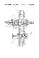
- FIG. 1is a partial longitudinal section illustrating the present shut-off valve with integral strainer connected in series with a conventional metering valve positioned upstream from the metering valve;
- FIG. 2is an enlarged longitudinal section of the shut-off valve with integral strainer illustrated in FIG. 1, in its closed position, and;
- FIG. 3is an enlarged longitudinal section of the shut-off valve with integral strainer illustrated in FIG. 1, in its opened position.
- a shut-off valve assembly 10is shown with its inlet connected to an inlet pipe 11 and its outlet connected to deliver fluid to a regulating valve assembly 12 that meters flow from the shut-off valve 10 to an outlet pipe 14 connected to deliver fluid under pressure to an industrial processing components such as in a refrigeration system.
- Valve 12forms no part of the present invention and is illustrated to show the function of the shut-off valve assembly 10 in an exemplary industrial processing system.
- Valve 12includes a metering valve member 15 biased toward its minimum flow position by spring 19 and it is positioned by a piston 16 driven by fluid pressure in an upper chamber 17 in cylinder 18 that reacts against a diaphram 22 biased by an adjustable spring assembly 23, chamber 17 communicates with upstream pressure through passage 20, and when fluid pressure in chamber 17 overcomes the force of spring assembly 23 on diaphram 22, it moves upwardly opening pilot port 24 and permitting flow through the port to the top side of piston 16, moving piston 16 downwardly against the biasing force of spring 19 to a balanced position.
- the shut-off valve assembly 10includes a sand cast valve body 26 having an inlet flange 27, an outlet flange 28, a central bonnet opening 30, a lower annular bottom plate opening 33, and a generally S-shaped partition wall 34 having a vertical portion 35, a horizontal portion 36, and another vertical portion 38.
- the partition wall 34separates the valve body into an inlet section 40 and an outlet section 41 connected only by a circular opening 43 in partition wall portion 36. Opening 43 includes a frustoconical valve seating surface 44.
- the inlet flange 27has an inlet opening 46 coaxially aligned with outlet flange 28 and outlet opening 47.
- valve stem 52is externally rotated by hand wheel 56 rotatably fixed to the upper end of the valve stem 52.
- the bonnet 49has an integral annular flange 58 that forms a shroud for the valve member assembly 54 when in its open position illustrated in FIG. 3.
- Upper annular flange 60 on valve body 26 and bonnet mounting surface 61 on its upper surfaceare positioned so that lower surface 62 of the shroud 58 lies above the uppermost flow line 63 of the inlet section 40. This permits the valve member assembly 54 to be completely withdrawn from the flow stream in its open position illustrated in FIG. 3.
- shroud 58isolates the rear side of the valve member assembly 54 from dynamic fluid pressure in all open positions of the valve.
- the bonnet 49is provided with an annular projection 70 that forms a stop for the valve member assembly 54 in its open position illustrated in Fig. 3, and it also functions to seal the rear surface of the valve member assembly 54 from static pressure.
- the valve member assembly 54includes a cylindrical valve member body 72 with annular recesses 73 and 74 at each end thereof that receive elastomeric annular seats 75 and 76, both of which are identical and have square cross-sections.
- Seat 76is the forward seat engageable with partition seat 44 in the closed position of the valve member illustrated in FIG. 2
- seat 75is the rear seat engageable with stop 70 when the valve member is in its open position illustrated in FIG. 3.
- valve seats 75 and 76are held against valve member body 72 by identical seat plates 78 and 79 with annular recesses 81 and 82 that receive the annular seats 75 and 76 respectively.
- valve member asesmbly 54is held axially against an integral flange 84 on valve stem 52 by a roll pin 85 that extends through a hole in the bottom of the valve stem 52 and reacts against a washer 86 that engages the seat plate 79.
- valve member assembly 54is reversible on the stem 52 by removing roll pin 85, sliding the valve assembly 54 off the valve stem and reversing and replacing it on the valve stem. This switches the annular seat 75 from the rear stop seat to the forward valve seat which, of course, is done when the original valve seat 76 becomes worn. Note that annular stop 70 engages the upper flat surface of the rear seat 75 so that any wear caused by the stop does not affect the performance of this seat when it is switched to the forward position because the forward seat engages the frustoconical partition seat 44 at the corner of the valve seat.
- valve seats 75 and 76is reversible itself in valve assembly 54 by removing the valve assembly 54 from the stem, separating the seat plates 78 and 79 from the seats 75 and 76, and then flipping the seats. This, of course, exposes unworn surfaces on the valve seats 75 and 76 to further extend seat life.
- the partition wall 34has a counterbore 88 that receives and locates an annular ring 89 on the upper end of a strainer 90 positioned in outlet section 41 of the valve body 26.
- the lower end of strainer 90has a ring 92 received and located in a counterbore 93 in bottom plate 94 that closes bottom plate opening 33 and is fastened to the valve body by fasteners 95.
- Bottom plate 94has a plug 96 threaded in a central bore 97 therein that provides access to the interior of the strainer assembly 90 if desired. Plug 96 can be used as a drain plug.
- the strainer assembly 90can be removed for cleaning and replacement simply by removing bottom plate 94 with the valve member 54 in its closed position. Note that the valve member 54 is in the inlet section 40 while the strainer assembly 90 is in outlet section 41. With valve member 94 closed, the outlet section 41 is isolated from system pressure permitting the plate 94 to be removed without exposure to system pressure.
- the positioning of the strainer assembly 90 in the outlet section 41 surrounding the partition opening 43 and in axial alignment with valve member 54permits fluid flow into the strainer internally and in an axial direction maximizing strainer effectiveness.
Landscapes
- Engineering & Computer Science (AREA)
- General Engineering & Computer Science (AREA)
- Chemical & Material Sciences (AREA)
- Chemical Kinetics & Catalysis (AREA)
- Mechanical Engineering (AREA)
- Lift Valve (AREA)
- Details Of Valves (AREA)
Abstract
Description
Claims (12)
Priority Applications (1)
| Application Number | Priority Date | Filing Date | Title |
|---|---|---|---|
| US07/028,876US4736766A (en) | 1987-03-24 | 1987-03-24 | Flow shut-off valve |
Applications Claiming Priority (1)
| Application Number | Priority Date | Filing Date | Title |
|---|---|---|---|
| US07/028,876US4736766A (en) | 1987-03-24 | 1987-03-24 | Flow shut-off valve |
Publications (1)
| Publication Number | Publication Date |
|---|---|
| US4736766Atrue US4736766A (en) | 1988-04-12 |
Family
ID=21846009
Family Applications (1)
| Application Number | Title | Priority Date | Filing Date |
|---|---|---|---|
| US07/028,876Expired - LifetimeUS4736766A (en) | 1987-03-24 | 1987-03-24 | Flow shut-off valve |
Country Status (1)
| Country | Link |
|---|---|
| US (1) | US4736766A (en) |
Cited By (13)
| Publication number | Priority date | Publication date | Assignee | Title |
|---|---|---|---|---|
| EP0636398A1 (en)* | 1993-07-26 | 1995-02-01 | Etablissements Robert Prulho | Installation for distillation of spirits |
| US5456285A (en)* | 1994-03-04 | 1995-10-10 | Lee; Jung S. | Globe valve with a strainer |
| US5469881A (en)* | 1993-06-04 | 1995-11-28 | Control Components Inc. | Valve assemblies |
| US5715858A (en)* | 1995-02-10 | 1998-02-10 | Johnson Service Company | Globe valve sticking prevention |
| US5803108A (en)* | 1996-12-09 | 1998-09-08 | International Marketing, Inc. | Tool and method for inserting a filter element into the valve stem of a wheel assembly |
| US20050121641A1 (en)* | 2003-12-09 | 2005-06-09 | Lim Howard T.S. | Vertical shut-off valve |
| GB2409259A (en)* | 2003-12-10 | 2005-06-22 | Danfoss As | Refrigerant valve arrangement |
| US20190032792A1 (en)* | 2017-07-31 | 2019-01-31 | Cameron International Corporation | Needle tip and seat for a choke valve |
| US20190383400A1 (en)* | 2018-06-19 | 2019-12-19 | Jiangsu Suyan Valve Machinery Co.,Ltd | Quantitative water adjusting valve |
| CN111503335A (en)* | 2020-04-30 | 2020-08-07 | 嵊州市浙江工业大学创新研究院 | A bottled liquefied petroleum gas pressure regulator with safety protection function |
| US20210301934A1 (en)* | 2020-03-30 | 2021-09-30 | Marshall Excelsior Co. | Combination valve |
| CN116498752A (en)* | 2023-06-28 | 2023-07-28 | 江苏杰航科技有限公司 | Corrosion-resistant valve body convenient to clean |
| CN120537906A (en)* | 2025-07-28 | 2025-08-26 | 江苏通达船用阀泵有限公司 | A self-closing discharge valve |
Citations (13)
| Publication number | Priority date | Publication date | Assignee | Title |
|---|---|---|---|---|
| DE253340C (en)* | ||||
| US485055A (en)* | 1892-10-25 | William j | ||
| US735039A (en)* | 1902-03-26 | 1903-07-28 | Meara Valve Company O | Valve. |
| US840860A (en)* | 1905-10-16 | 1907-01-08 | Otto Mueller | Faucet. |
| US1204106A (en)* | 1916-04-26 | 1916-11-07 | John J Wing | Tender-tank valve. |
| US1898816A (en)* | 1929-12-18 | 1933-02-21 | George M Crossen | Valve |
| US2067229A (en)* | 1935-03-04 | 1937-01-12 | William T Birch | Relief valve |
| CH202038A (en)* | 1938-03-26 | 1938-12-31 | Sauter Ag | Valve manifold for hot water storage tank. |
| GB611691A (en)* | 1945-05-07 | 1948-11-02 | British Thomson Houston Co Ltd | Improvements in and relating to valves |
| US3115154A (en)* | 1960-12-27 | 1963-12-24 | Watts Regulator Co | Pressure regulator with integral relief valve |
| US3286979A (en)* | 1963-09-16 | 1966-11-22 | Westinghouse Electric Corp | Valve structure |
| US3960358A (en)* | 1975-02-11 | 1976-06-01 | Rudolf Vollmer | Pressure reducer |
| DE2535902A1 (en)* | 1975-08-12 | 1977-02-24 | At Armaturen Technik Gmbh | Manual damped filtering flow control valve - has tapered collar to ensure gradual flow rate change |
- 1987
- 1987-03-24USUS07/028,876patent/US4736766A/ennot_activeExpired - Lifetime
Patent Citations (13)
| Publication number | Priority date | Publication date | Assignee | Title |
|---|---|---|---|---|
| DE253340C (en)* | ||||
| US485055A (en)* | 1892-10-25 | William j | ||
| US735039A (en)* | 1902-03-26 | 1903-07-28 | Meara Valve Company O | Valve. |
| US840860A (en)* | 1905-10-16 | 1907-01-08 | Otto Mueller | Faucet. |
| US1204106A (en)* | 1916-04-26 | 1916-11-07 | John J Wing | Tender-tank valve. |
| US1898816A (en)* | 1929-12-18 | 1933-02-21 | George M Crossen | Valve |
| US2067229A (en)* | 1935-03-04 | 1937-01-12 | William T Birch | Relief valve |
| CH202038A (en)* | 1938-03-26 | 1938-12-31 | Sauter Ag | Valve manifold for hot water storage tank. |
| GB611691A (en)* | 1945-05-07 | 1948-11-02 | British Thomson Houston Co Ltd | Improvements in and relating to valves |
| US3115154A (en)* | 1960-12-27 | 1963-12-24 | Watts Regulator Co | Pressure regulator with integral relief valve |
| US3286979A (en)* | 1963-09-16 | 1966-11-22 | Westinghouse Electric Corp | Valve structure |
| US3960358A (en)* | 1975-02-11 | 1976-06-01 | Rudolf Vollmer | Pressure reducer |
| DE2535902A1 (en)* | 1975-08-12 | 1977-02-24 | At Armaturen Technik Gmbh | Manual damped filtering flow control valve - has tapered collar to ensure gradual flow rate change |
Cited By (24)
| Publication number | Priority date | Publication date | Assignee | Title |
|---|---|---|---|---|
| US5469881A (en)* | 1993-06-04 | 1995-11-28 | Control Components Inc. | Valve assemblies |
| EP0636398A1 (en)* | 1993-07-26 | 1995-02-01 | Etablissements Robert Prulho | Installation for distillation of spirits |
| FR2708280A1 (en)* | 1993-07-26 | 1995-02-03 | Prulho Ets Robert | Brandy distillation installation. |
| US5456285A (en)* | 1994-03-04 | 1995-10-10 | Lee; Jung S. | Globe valve with a strainer |
| US5715858A (en)* | 1995-02-10 | 1998-02-10 | Johnson Service Company | Globe valve sticking prevention |
| US5803108A (en)* | 1996-12-09 | 1998-09-08 | International Marketing, Inc. | Tool and method for inserting a filter element into the valve stem of a wheel assembly |
| US20050121641A1 (en)* | 2003-12-09 | 2005-06-09 | Lim Howard T.S. | Vertical shut-off valve |
| US7000898B2 (en) | 2003-12-09 | 2006-02-21 | Howard Tak Su Lim | Vertical shut-off valve |
| GB2409259A (en)* | 2003-12-10 | 2005-06-22 | Danfoss As | Refrigerant valve arrangement |
| US20050155376A1 (en)* | 2003-12-10 | 2005-07-21 | Danfoss A/S | Refrigerant valve arrangement |
| US7328593B2 (en) | 2003-12-10 | 2008-02-12 | Danfoss A/S | Refrigerant valve arrangement |
| GB2409259B (en)* | 2003-12-10 | 2008-12-31 | Danfoss As | Refrigerant valve arrangement |
| US20190032792A1 (en)* | 2017-07-31 | 2019-01-31 | Cameron International Corporation | Needle tip and seat for a choke valve |
| US10830359B2 (en)* | 2017-07-31 | 2020-11-10 | Cameron International Corporation | Needle tip and seat for a choke valve |
| US11549593B2 (en) | 2017-07-31 | 2023-01-10 | Cameron International Corporation | Needle tip and seat for a choke valve |
| US11796068B2 (en) | 2017-07-31 | 2023-10-24 | Cameron International Corporation | Needle tip and seat for a choke valve |
| US12152680B2 (en) | 2017-07-31 | 2024-11-26 | Cameron International Corporation | Needle tip and seat for a choke valve |
| US20190383400A1 (en)* | 2018-06-19 | 2019-12-19 | Jiangsu Suyan Valve Machinery Co.,Ltd | Quantitative water adjusting valve |
| US20210301934A1 (en)* | 2020-03-30 | 2021-09-30 | Marshall Excelsior Co. | Combination valve |
| US11841086B2 (en)* | 2020-03-30 | 2023-12-12 | Marshall Excelsior Co. | Combination valve |
| CN111503335A (en)* | 2020-04-30 | 2020-08-07 | 嵊州市浙江工业大学创新研究院 | A bottled liquefied petroleum gas pressure regulator with safety protection function |
| CN116498752A (en)* | 2023-06-28 | 2023-07-28 | 江苏杰航科技有限公司 | Corrosion-resistant valve body convenient to clean |
| CN116498752B (en)* | 2023-06-28 | 2023-09-15 | 江苏杰航科技有限公司 | Corrosion-resistant valve body convenient to clean |
| CN120537906A (en)* | 2025-07-28 | 2025-08-26 | 江苏通达船用阀泵有限公司 | A self-closing discharge valve |
Similar Documents
| Publication | Publication Date | Title |
|---|---|---|
| US4776365A (en) | Non-turbulent shut-off valve | |
| US4736766A (en) | Flow shut-off valve | |
| US3000608A (en) | Stock valve | |
| US2841359A (en) | Shut-off valve | |
| CA2172536C (en) | Poppet valve having external adjustment for a flow restrictor | |
| US3722860A (en) | Cage valve assembly | |
| US2747607A (en) | Pressure regulator | |
| US2830784A (en) | General purpose flow valve with alternative fluid pressure or manual control | |
| US6135142A (en) | Control valve device | |
| US3777889A (en) | Cartridge filter unit | |
| US3446241A (en) | Flow control valve with plural diaphragm operator | |
| US3561468A (en) | Universal control valve | |
| US4028254A (en) | Fluid filter | |
| US4246928A (en) | Restricted movement valve seats for an expanding gate valve | |
| US2989082A (en) | Valve structure having angularly movable slide with shear seals | |
| US5217046A (en) | Top entry flow control valve with two sets of orifices | |
| US5503180A (en) | Valve having easily replaceable seat | |
| KR930011495B1 (en) | Non-rising stem valve assembly and method of replacing a permanent seal | |
| US4662395A (en) | Pressurized liquid flushing valve arrangement with a shut-off sleeve | |
| US3348570A (en) | Valve assembly for isolating controlled fluid from valve housing | |
| US3749355A (en) | Venturi-ball valve no. 103 | |
| US1945834A (en) | Valve | |
| US4295489A (en) | Pilot-operated back pressure regulator | |
| US4027696A (en) | Check valve | |
| US3779508A (en) | Venturi-ball valve |
Legal Events
| Date | Code | Title | Description |
|---|---|---|---|
| AS | Assignment | Owner name:BATHRICK, LEELAND M. Free format text:ASSIGNMENT OF ASSIGNORS INTEREST.;ASSIGNOR:DOBBS, LADDIE F.;REEL/FRAME:004695/0174 Effective date:19870320 | |
| STCF | Information on status: patent grant | Free format text:PATENTED CASE | |
| FPAY | Fee payment | Year of fee payment:4 | |
| FPAY | Fee payment | Year of fee payment:8 | |
| REMI | Maintenance fee reminder mailed | ||
| FPAY | Fee payment | Year of fee payment:12 | |
| AS | Assignment | Owner name:HUBBELL SPECIAL PRODUCTS, INC., WISCONSIN Free format text:ASSIGNMENT OF ASSIGNORS INTEREST;ASSIGNOR:BATHRICK, LEELAND M.;REEL/FRAME:012607/0007 Effective date:20011120 Owner name:PARKER-HANNIFIN CORPORATION, OHIO Free format text:ASSIGNMENT OF ASSIGNORS INTEREST;ASSIGNOR:HUBBELL SPECIAL PRODUCTS, INC.;REEL/FRAME:012607/0083 Effective date:20011120 | |
| AS | Assignment | Owner name:PARKER HANNIFIN CUSTOMER SUPPORT INC., CALIFORNIA Free format text:ASSIGNMENT OF ASSIGNORS INTEREST;ASSIGNOR:PARKER-HANNIFIN CORPORATION;REEL/FRAME:012928/0198 Effective date:20020508 | |
| AS | Assignment | Owner name:PARKER INTANGIBLES LLC, OHIO Free format text:MERGER;ASSIGNOR:PARKER HANNIFIN CUSTOMER SUPPORT INC.;REEL/FRAME:015215/0522 Effective date:20030630 |