US4736744A - Laser coagulation system - Google Patents
Laser coagulation systemDownload PDFInfo
- Publication number
- US4736744A US4736744AUS06/919,320US91932086AUS4736744AUS 4736744 AUS4736744 AUS 4736744AUS 91932086 AUS91932086 AUS 91932086AUS 4736744 AUS4736744 AUS 4736744A
- Authority
- US
- United States
- Prior art keywords
- laser beam
- laser
- disc
- slit image
- optical
- Prior art date
- Legal status (The legal status is an assumption and is not a legal conclusion. Google has not performed a legal analysis and makes no representation as to the accuracy of the status listed.)
- Expired - Fee Related
Links
Images


Classifications
- A—HUMAN NECESSITIES
- A61—MEDICAL OR VETERINARY SCIENCE; HYGIENE
- A61F—FILTERS IMPLANTABLE INTO BLOOD VESSELS; PROSTHESES; DEVICES PROVIDING PATENCY TO, OR PREVENTING COLLAPSING OF, TUBULAR STRUCTURES OF THE BODY, e.g. STENTS; ORTHOPAEDIC, NURSING OR CONTRACEPTIVE DEVICES; FOMENTATION; TREATMENT OR PROTECTION OF EYES OR EARS; BANDAGES, DRESSINGS OR ABSORBENT PADS; FIRST-AID KITS
- A61F9/00—Methods or devices for treatment of the eyes; Devices for putting in contact-lenses; Devices to correct squinting; Apparatus to guide the blind; Protective devices for the eyes, carried on the body or in the hand
- A61F9/007—Methods or devices for eye surgery
- A61F9/008—Methods or devices for eye surgery using laser
- A61F9/00821—Methods or devices for eye surgery using laser for coagulation
- A—HUMAN NECESSITIES
- A61—MEDICAL OR VETERINARY SCIENCE; HYGIENE
- A61F—FILTERS IMPLANTABLE INTO BLOOD VESSELS; PROSTHESES; DEVICES PROVIDING PATENCY TO, OR PREVENTING COLLAPSING OF, TUBULAR STRUCTURES OF THE BODY, e.g. STENTS; ORTHOPAEDIC, NURSING OR CONTRACEPTIVE DEVICES; FOMENTATION; TREATMENT OR PROTECTION OF EYES OR EARS; BANDAGES, DRESSINGS OR ABSORBENT PADS; FIRST-AID KITS
- A61F9/00—Methods or devices for treatment of the eyes; Devices for putting in contact-lenses; Devices to correct squinting; Apparatus to guide the blind; Protective devices for the eyes, carried on the body or in the hand
- A61F9/007—Methods or devices for eye surgery
- A61F9/008—Methods or devices for eye surgery using laser
- A61F2009/00861—Methods or devices for eye surgery using laser adapted for treatment at a particular location
- A61F2009/00863—Retina
- A—HUMAN NECESSITIES
- A61—MEDICAL OR VETERINARY SCIENCE; HYGIENE
- A61F—FILTERS IMPLANTABLE INTO BLOOD VESSELS; PROSTHESES; DEVICES PROVIDING PATENCY TO, OR PREVENTING COLLAPSING OF, TUBULAR STRUCTURES OF THE BODY, e.g. STENTS; ORTHOPAEDIC, NURSING OR CONTRACEPTIVE DEVICES; FOMENTATION; TREATMENT OR PROTECTION OF EYES OR EARS; BANDAGES, DRESSINGS OR ABSORBENT PADS; FIRST-AID KITS
- A61F9/00—Methods or devices for treatment of the eyes; Devices for putting in contact-lenses; Devices to correct squinting; Apparatus to guide the blind; Protective devices for the eyes, carried on the body or in the hand
- A61F9/007—Methods or devices for eye surgery
- A61F9/008—Methods or devices for eye surgery using laser
- A61F2009/00885—Methods or devices for eye surgery using laser for treating a particular disease
- A61F2009/00891—Glaucoma
- A—HUMAN NECESSITIES
- A61—MEDICAL OR VETERINARY SCIENCE; HYGIENE
- A61F—FILTERS IMPLANTABLE INTO BLOOD VESSELS; PROSTHESES; DEVICES PROVIDING PATENCY TO, OR PREVENTING COLLAPSING OF, TUBULAR STRUCTURES OF THE BODY, e.g. STENTS; ORTHOPAEDIC, NURSING OR CONTRACEPTIVE DEVICES; FOMENTATION; TREATMENT OR PROTECTION OF EYES OR EARS; BANDAGES, DRESSINGS OR ABSORBENT PADS; FIRST-AID KITS
- A61F9/00—Methods or devices for treatment of the eyes; Devices for putting in contact-lenses; Devices to correct squinting; Apparatus to guide the blind; Protective devices for the eyes, carried on the body or in the hand
- A61F9/007—Methods or devices for eye surgery
- A61F9/008—Methods or devices for eye surgery using laser
- A61F9/009—Auxiliary devices making contact with the eyeball and coupling in laser light, e.g. goniolenses
Definitions
- This inventionrelates to a laser coagulation system, and more particularly to a laser coagulation system adapted for use in an ophthalological treatment in which a laser beam from a laser source is radiated into a patient's eye to develop a large amount of heat effective to cause thermal coagulation at a predetermined portion of the biological organism in the eyeball of a patient.
- the laser coagulation systemincludes a laser beam projector for producing a laser beam from an argon or krypton laser, which is condensed to a laser beam of a predetermined diameter, directed toward a predetermined portion of the eyeball to be coagulated, and then focused thereon as a laser spot for thermal coagulation.
- the laser coagulation systemfurther comprises a slit image projector for forming a slit image on the eyeball to illuminate the background and to determine the predetermined portion of eyeball to be coagulated.
- This type of laser coagulation systemis further provided with an observation equipment for observing the slit image and the laser beam projected onto the eyeball to be coagulated. Doctors always observe the eyeball by means of the observation equipment to be able to accurately perform the laser beam projection onto the eyeball to be coagulated. Some of the laser beam is usually reflected back from the irradiated eye portion into the eyes of the doctor through the observation equipment, thus resulting in damage to his eyes.
- a safety filteris provided to absorb laser energy reflected into the observation equipment.
- the prior art coagulation systemhas the drawback that the safety filter corresponding to the laser beam being used must be attached to the observation equipment every time it is used. This can eventually lead to a big problem in that the selection of the wrong safety filter can cause a serious injury.
- a laser coagulation systemcomprises a laser source for selectively producing one of a plurality of laser beams each different in wavelength, a slit image projector for projecting a slit image into the eyeball to determine the selected portion to be coagulated in the eyeball, a laser beam projector for projecting selected one of the laser beams onto the selected portion to be coagulated, an observation equipment having an optical path aligned to an observer for observing the slit image and the laser beam projected onto the eyeball, and a plurality of safety filters, each corresponding to one of the laser beams and mounted within the devisvation equipment for absorbing the most energy relative to the corresponding laser beam, respectively.
- One of the safety filtersis selected and brought into the observation optical path in response to the selection of either one of the laser beams, thus absorbing a substantial part of the laser energy that is reflected into the observation equipment and reducing the reflected laser energy to a level that is safe for the observer.
- a safety filter corresponding to the selected laser beamis automatically brought into the optical path of the observation equipment to cut a substantial part of energy reflected back to the observer at the time the selected laser beam is being projected onto the eye portion to be coagulated.
- argon and krypton laser beamsare employed, and safety filters for argon and krypton laser beams are mounted on first and second coaxial discs, which are selectively rotated in response to the selection of argon or krypton laser beam to bring the safety filter for argon or krypton laser beam to the optical path of the observation equipment.
- FIG. 1is a perspective view showing a whole appearance of a laser coagulation system of the present invention
- FIG. 2is an illustrative view showing the arrangement of an optical system for a laser beam projector, slit image projector and observation equipment used in the laser coagulation system of the present invention
- FIG. 3is a perspective view showing the arrangement of the optical system in FIG. 2;
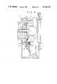
- FIG. 4is a cross-sectional view showing the structure of a safety filter assembly as viewed in the direction parallel to the optical path of the observation equipment;
- FIG. 5is a cross-sectional view showing the structure of a safety filter assembly as viewed in the direction perpendicular to the optical path of the observation equipment.
- FIG. 1shows the appearance of a laser coagulation or laser beam delivery system according to the present invention which includes a slider 11 mounted on a base plate 10 so as to be slidable relative to the base plate 10 in a direction X or Y by means of a manipulator 12 such as a joy stick.
- the displacement of the slider 11 relative to the base plate 10can be effected by operating the manipulator 12 in the directions X and Y.
- the slider 11supports thereon an instrument base 53 on which a slit image projector 20, a laser beam projector 21 and an observation equipment 50 are mounted as will be fully described later.
- the manipulator 12is further provided with a handle 12a, the rotation of which allows the instrument base 53 to move upwardly or downwardly to displace the projectors 20 and 21 together with the observation equipment 50 vertically.
- the manipulator 12can adjust the position of the instrument base 53 in the directions X and Y and in the vertical direction.
- the thus adjusted slider 11can be locked on the base plate 10 by means of a lock 12b.
- the base plate 10has on its front edge two poles 13 between which a chin support 14 and a forehead pad 15 are fixedly mounted.
- a patientsits down in front of the apparatus with his chin against the support 14 and his forehead against the pad 15 and watches an eye fixation lamp 16a which serves to fix the patient's eye during measurement or coagulation.
- the slit image projector 20which is pivotable about the axis A (see FIG. 2) and irradiates an illuminating beam to project a slit image onto the eyeball to illuminate the background and determine the portion of the eye to be measured or coagulated or the treatment point.
- the slit image projector 20is arranged coaxially with the laser beam projector 21 for projecting a laser beam from a source 40 such as an argon or krypton laser through an optical fiber 41 onto that portion to be coagulated in the eyeball.
- the observation equipment for observing the focussed laser beam or imaged slit in the eyeballis further arranged on the front edge of the slider 11 so as to be rotatable about the same axis as the turning axis A for the slit image projector 20.
- FIGS. 2 and 3show the detailed arrangement of an optical system for the laser beam projector 21, slit image projector 20 and observation equipment 50.
- the slit image projector 20is arranged in a housing 22 mounted so as to be rotatable about the axis A and is provided therein with a lamp 24 which is adjustable in intensity by means of an adjusting knob 23 (see FIG. 1).
- the lamp 24emits illuminating light beam, which is converged by condensor lenses 25 and 25' to illuminate a slit aperture 26.
- Arranged between the condenser lens 25 and slit aperture 26are a roof-shaped prism 27, an infrared ray cutting filter 28 and a detachable blue filter 29.
- the illuminated slit aperture 26is imaged, for example, onto a retina 34 of a patient's eye 33 as a slit image 34' by means of a focussing lens 30 including lenses 30a and 30b.
- a special contact lens(not shown) is attached to the patient's eye.
- a mirror assembly 35 having three-divided mirror portions 35a to 35cis mounted between the patient's eye 33 and lens 30b.
- the central mirror portion 35bcan, as described later, be turned upwardly, downwardly, leftwardly or rightwardly about an axis perpendicular to or within the paper surface (in FIG. 2) by means of an operating lever 12c of the manipulator 12.
- the deflection prism 27Arranged between the lens 30a and a prism 31 is a screen plate 36 which serves to interrupt the arrival of slit light to the central mirror 35a, while permitting it to reach the upper and lower mirrors 35b, 35c to the retina 34.
- the deflection prism 27has one surface 27a angled to deflect light toward the lower mirror 35b and the other surface 27b also angled to deflect light toward the upper mirror 35c.
- the deflection prismfunctions to form the filament image of the lamp 24 at two points existing on the entrance pupil of the focussing lens 30.
- the slit width and length of the slit aperture 26are adjustable by adjusting knobs 37 and 38 and the intensity of the lamp 24 is adjustable by an adjusting knob 23.
- the laser beam projector 21is, on the other hand, arranged in the same housing 22 as the slit image projector 20.
- the laser beam passing through the optical fiber 41 from the laser source 40is deflected rectangularly at a prism 42 toward a variator lens 43 and a lens 44, reflected at the prism 31 and then advanced along the same optical path or axis as the slit image projector 20 through the lens 30b, mirror 35a and contact lens to radiate the laser spot of a predetermined diameter on the retina 34 for thermal coagulation.
- the spot diameter of the laser beamcan be adjusted in the range of about 50 ⁇ m to 1 mm by turning a knob 45 and adjusting the variator lens 43.
- the instrument base 53(FIG. 1) is provided with the housing 22 for accommodating the projectors 20 and 21 and a housing 52 for accommodating the observation equipment 50, and is displaceable vertically using the handle 12a of the manipulator 12 as mentioned before. Further, the housings 22 and 52 are turnable to each other about the axis A. so that the projectors 20, 21 and the observation equipment 50 can effect upward, downward or turning movement, respectively.
- the observation equipment 50includes an optical system comprised of an objective 55, variator lenses 56 and 56', a safety filter 61, a focussing lens 57, erecting prisms 58 and 58', and eyepieces 51, 51'.
- the observation equipment 50allows the observation of the slit image and laser spot formed in the eyeball.
- the adjustment of a knob 60causes the variator lens 56 to be adjusted to provide an enlarged or reduced slit image or laser spot.
- the safety filter 61is used to interrupt the laser beam reflected back from the irradiated portion of eye or cornea and protect the eyes of an observer. For this purpose, the safety filter 61 is automatically inserted into the optical path of the observation equipment 50 immediately before the laser source 40 is activated to produce a stronger laser beam.
- optical elements following the objective 55are provided in pairs respectively to allow binocular observation.
- FIGS. 4 and 5describe the structure of the safety filter assembly 61 in detail.
- FIG. 4shows in cross section a side face of the safety filter assembly as viewed in the same direction as in the observation equipment 50 in FIG. 2 with optical elements such as the objective 55, imaging lens 57, etc. being removed therefrom.
- the safety filter assemblyis accommodated in a housing 70 on one side of which an adapter 71 is provided for connection to a housing for the objective lens 55 and variator lens 56 (FIG. 2).
- an adapter 71is provided for connection to a housing for the objective lens 55 and variator lens 56 (FIG. 2).
- another adapter 73is provided for accommodating the imaging lens 57 which is fixed thereto by a screw 72.
- the adapter 71is also provided therein with a shaft 74 extending parallel relative to the optical axis into the housing 70 in which the shaft 74 rotatably carries an optical disc 75 bearing argon filters.
- the disc 75is, as shown in FIG. 5, horseshoe-shaped and formed thereon with aperture means in the form of a semicicrcular cutout 75a and a circular opening 75b which are arranged symmetrically with respect to the shaft 74 and come into alignment with the optical path to the eyepiece 51.
- the disc 75carries argon filters 76 along a line perpendicular to the diametric line connecting the centers of the cutout 75a and opening 75b, the cutout 75a and opening 75b existing on the circumference of a circle about the shaft 74.
- the disc 75further has straight portions 75c and 75d which extend to the cutout 75a and come into contact with a pin 78 fixed to the housing 70 through a bracket 77 to limit rotation of the disc 75 in clockwise and counterclockwise directions, respectively.
- the pin 78is provided on its circumference with an elastic member 78a for absorbing impact due to contact of the pin 78 with the portions 75c and 75d.
- the disc 75is further provided with a photointerrupter 79 extending upwardly from the disc's surface and diametrically opposed to the pin 78.
- the photointerrupter 79is, as shown in FIG. 4, L-shaped and constructed to be able to pass through a photocoupler 80 for the argon laser and a photocoupler 81 for the krypton laser which are spaced diametrically relative to a line connecting the pin 78 and photointerrupter 79.
- the disc 75is formed with a gear portion 75a on its whole circumference except for the cutout 75a and straight portions 75c and 75d.
- disc 82On the shaft 74 there is rotatably mounted another disc 82 which is coaxially substantially the same in shape as disc 75, but thicker and provided with krypton filters 83 and 84 which are arranged in pairs at the same positions as the filters on the other disc 75, and one pair of which is inclined relative to the other pair of filters at an angle of about 10 degrees to scatter a part of the krypton laser back to the other for reflection therebetween, thereby weakening its energy.
- This disc 82is also formed with a gear portion 82a on its circumference.
- the observation equipment 50is, on the other hand, provided in the housing 70 with a rotary solenoid 86 for the argon laser filter and a rotary solenoid 87 for the krypton laser filter 87, both of which are mounted on a support 85 fixed to the housing 70.
- the rotary solenoid 86is provided with an output shaft 86a to which a gear 88 with a non-toothed portion is fixed and to which a return spring 89 is also mounted.
- the gear 88engages with a pinion gear 92 integral with a gear 91 which is rotatably mounted on a shaft 90 to come into engagment with the gear 75a of the disc 75 for the argon filter.
- the other rotary solenoid 87is provided with an output shaft 93 to which a gear 94 with non-toothed portion is fixed and to which a return spring 99 is fixed.
- the gear 94engages with a pinion gear 97 integral with a gear 96 which is rotatably mounted on a shaft 95 to come into engagement with the gear 82a of the disc 82 for the krypton filters.
- the disc 82is provided with a photo-interrupter 98 which extends perpendicularly to the disc surface and is phase-shifted by 180 degrees relative to the photo-interrupter 79 for the argon disc 75.
- the patientfirst sits down with his chin against the support 14 and his forehead against the pad 15 and watches the eye fixation lamp 16. he lamp 24 of the slit image projector 20 is then turned on to form the slit image 34' on the retina 34 of the patient's eye 33 through the contact lens set thereon.
- the slit lighthas its central flux inhibited to arrive at the central mirror 35a by means by the screen plate 36 and is reflected only at the upper and lower mirrors 35b and 35c to form the slit image 34' on the retina 34.
- the deflection prismis used to deflect the slit light towards the mirrors 35b and 35c effectively.
- the intensity of the slit imagecan be adjusted by the knob 23, and the slit width and length can be adjusted by the adjusting knobs 37 and 38.
- the manipulator 12may be operated to displace the slider 11 and the housings 22 and 52 in the directions X, Y and Z and turn the projectors 20, 21 or observation equipment 50 about the axis A relative to each other until the slit image is formed on the desired portion for coagulation.
- the thus formed slit image 34'can be observed by the optical system of the observation equipment including the objective 55, variator lens 56, imaging lens 57, erecting prism 58 and eyepiece 51.
- the laser source 40is activated to emit a week laser beam, which is caused to pass through the prism 42, variator lens 43, lens 44, prism 31, and lens 30b, reflected at the central mirror 35a and then focussed as a spot onto the retina 34.
- a stronger laser beamis generated from the laser source 40 by changing power.
- the safety filteris automatically inserted into the optical path of the observation equipment 50 to protect the eyes of the observer from the laser beam reflected at the irradiated portion of the patients eye or retina.
- the laser spot on the retina 34can be displaced by scanning the central mirror 35a vertically or horizontally, that is, in the direction X or Y using the operating lever 12c of the manipulator 12.
- the shutter(not shown) provided on the side of the laser source 40 is closed and discs 72 and 82 for the argon and krypton filters take a positon as shown in FIG. 5 where the return springs 88 and 99 return the rotary solenoids 86, 87 and the gears 88, 94 to their respective starting positions.
- the disc 75In the position shown in FIG. 5, the disc 75 is stopped with its straight portion 75c against the pin 78, and the cutout 75a and opening 75b come into the binocular optical path of the eyepieces 51 to allow the observer to observe the eyeball illuminated by the slit image projector 20.
- the disc 82 for the krypton lasertakes the same position as the disc 75 for the argon laser although the former is not visible in FIG. 5.
- a switch(not shown) on the console panel is operated to activate the rotary solenoid 86 and turn the gear 89 counterclockwise in FIG. 5. This causes the clockwise roation of the gear 91 and counterclockwise rotation of the disc 75.
- the disc 82functions similarly to the disc 75 with only the difference being that the rotary solenoid 87 is activated instead of the rotary solenoid 86.
- the detection of rotation of the disc 82 by 90 degreesis made in cooperation with the photocoupler 81 and photo-interrupter 98.
- the selection of the argon or krypton laserdepends upon the condition or state of a portion to be irradiated, and the selected laser beam is projected as a spot causing no harm with very little energy.
- blind coversas indicated by reference numerals 100 and 101, are provided. These covers can be removed, if necessary, so that an optical bypass system can be attached to allow observation by a third party.
Landscapes
- Health & Medical Sciences (AREA)
- Ophthalmology & Optometry (AREA)
- Heart & Thoracic Surgery (AREA)
- Vascular Medicine (AREA)
- Optics & Photonics (AREA)
- Surgery (AREA)
- Engineering & Computer Science (AREA)
- Biomedical Technology (AREA)
- Physics & Mathematics (AREA)
- Nuclear Medicine, Radiotherapy & Molecular Imaging (AREA)
- Life Sciences & Earth Sciences (AREA)
- Animal Behavior & Ethology (AREA)
- General Health & Medical Sciences (AREA)
- Public Health (AREA)
- Veterinary Medicine (AREA)
- Laser Surgery Devices (AREA)
- Eye Examination Apparatus (AREA)
Abstract
Description
Claims (16)
Applications Claiming Priority (2)
| Application Number | Priority Date | Filing Date | Title |
|---|---|---|---|
| JP60-231317 | 1985-10-18 | ||
| JP60231317AJPS6294154A (en) | 1985-10-18 | 1985-10-18 | Laser photocoagulation device |
Publications (1)
| Publication Number | Publication Date |
|---|---|
| US4736744Atrue US4736744A (en) | 1988-04-12 |
Family
ID=16921737
Family Applications (1)
| Application Number | Title | Priority Date | Filing Date |
|---|---|---|---|
| US06/919,320Expired - Fee RelatedUS4736744A (en) | 1985-10-18 | 1986-10-14 | Laser coagulation system |
Country Status (4)
| Country | Link |
|---|---|
| US (1) | US4736744A (en) |
| EP (1) | EP0230095B1 (en) |
| JP (1) | JPS6294154A (en) |
| DE (1) | DE3680315D1 (en) |
Cited By (32)
| Publication number | Priority date | Publication date | Assignee | Title |
|---|---|---|---|---|
| US5000561A (en)* | 1988-10-06 | 1991-03-19 | Lasag Ag | Control arrangement for an apparatus for ophthalmological treatment |
| US5311224A (en)* | 1991-10-04 | 1994-05-10 | Nidek Co., Ltd. | Optical ophthalmic treatment apparatus |
| US5400428A (en)* | 1992-05-13 | 1995-03-21 | Spectranetics Corporation | Method and apparatus for linearly scanning energy over an optical fiber array and coupler for coupling energy to the optical fiber array |
| US5425729A (en)* | 1985-10-18 | 1995-06-20 | Kowa Company Ltd. | Laser coagulation system |
| US5795351A (en)* | 1996-11-19 | 1998-08-18 | Visx, Incorporated | Laser refractive surgery station |
| US20040199149A1 (en)* | 1996-03-21 | 2004-10-07 | Myers Raymond I. | Lenticular refractive surgery of presbyopia, other refractive errors, and cataract retardation |
| US8262646B2 (en) | 2006-01-20 | 2012-09-11 | Lensar, Inc. | System and method for providing the shaped structural weakening of the human lens with a laser |
| US8382745B2 (en) | 2009-07-24 | 2013-02-26 | Lensar, Inc. | Laser system and method for astigmatic corrections in association with cataract treatment |
| US8452372B2 (en) | 2010-10-13 | 2013-05-28 | Gholam Peyman | System for laser coagulation of the retina from a remote location |
| US8465478B2 (en) | 2009-07-24 | 2013-06-18 | Lensar, Inc. | System and method for performing LADAR assisted procedures on the lens of an eye |
| US8480659B2 (en) | 2008-07-25 | 2013-07-09 | Lensar, Inc. | Method and system for removal and replacement of lens material from the lens of an eye |
| US8500723B2 (en) | 2008-07-25 | 2013-08-06 | Lensar, Inc. | Liquid filled index matching device for ophthalmic laser procedures |
| US8556425B2 (en) | 2010-02-01 | 2013-10-15 | Lensar, Inc. | Purkinjie image-based alignment of suction ring in ophthalmic applications |
| USD694890S1 (en) | 2010-10-15 | 2013-12-03 | Lensar, Inc. | Laser system for treatment of the eye |
| USD695408S1 (en) | 2010-10-15 | 2013-12-10 | Lensar, Inc. | Laser system for treatment of the eye |
| US8617146B2 (en) | 2009-07-24 | 2013-12-31 | Lensar, Inc. | Laser system and method for correction of induced astigmatism |
| US8758332B2 (en) | 2009-07-24 | 2014-06-24 | Lensar, Inc. | Laser system and method for performing and sealing corneal incisions in the eye |
| US8801186B2 (en) | 2010-10-15 | 2014-08-12 | Lensar, Inc. | System and method of scan controlled illumination of structures within an eye |
| US8903468B2 (en) | 2010-10-13 | 2014-12-02 | Gholam Peyman | Laser coagulation of an eye structure from a remote location |
| US9037217B1 (en) | 2010-10-13 | 2015-05-19 | Gholam A. Peyman | Laser coagulation of an eye structure or a body surface from a remote location |
| US9180051B2 (en) | 2006-01-20 | 2015-11-10 | Lensar Inc. | System and apparatus for treating the lens of an eye |
| USD753309S1 (en)* | 2013-09-09 | 2016-04-05 | Kowa Company, Ltd. | Slit lamp |
| US9375349B2 (en) | 2006-01-20 | 2016-06-28 | Lensar, Llc | System and method for providing laser shot patterns to the lens of an eye |
| US9393154B2 (en) | 2011-10-28 | 2016-07-19 | Raymond I Myers | Laser methods for creating an antioxidant sink in the crystalline lens for the maintenance of eye health and physiology and slowing presbyopia development |
| US9510974B1 (en) | 2010-10-13 | 2016-12-06 | Gholam A. Peyman | Laser coagulation of an eye structure or a body surface from a remote location |
| US9545338B2 (en) | 2006-01-20 | 2017-01-17 | Lensar, Llc. | System and method for improving the accommodative amplitude and increasing the refractive power of the human lens with a laser |
| US9889043B2 (en) | 2006-01-20 | 2018-02-13 | Lensar, Inc. | System and apparatus for delivering a laser beam to the lens of an eye |
| US9931171B1 (en) | 2010-10-13 | 2018-04-03 | Gholam A. Peyman | Laser treatment of an eye structure or a body surface from a remote location |
| US10456209B2 (en) | 2010-10-13 | 2019-10-29 | Gholam A. Peyman | Remote laser treatment system with dynamic imaging |
| US10463541B2 (en) | 2011-03-25 | 2019-11-05 | Lensar, Inc. | System and method for correcting astigmatism using multiple paired arcuate laser generated corneal incisions |
| US20210045915A1 (en)* | 2018-02-02 | 2021-02-18 | Xinova, LLC | Laser ophthalmic treatment system with time-gated image capture component and electronic display |
| US11309081B2 (en) | 2010-10-13 | 2022-04-19 | Gholam A. Peyman | Telemedicine system with dynamic imaging |
Families Citing this family (4)
| Publication number | Priority date | Publication date | Assignee | Title |
|---|---|---|---|---|
| JPH0530415Y2 (en)* | 1988-02-13 | 1993-08-04 | ||
| DE4017441A1 (en)* | 1990-05-30 | 1991-12-05 | Weimel Erich | LASER SYSTEM |
| US5408484A (en)* | 1990-05-30 | 1995-04-18 | Weimel; Erich | Switchable energy supply for a laser system |
| JP3929735B2 (en)* | 2001-10-03 | 2007-06-13 | 独立行政法人科学技術振興機構 | Intraocular illumination probe and ophthalmic surgical apparatus |
Citations (6)
| Publication number | Priority date | Publication date | Assignee | Title |
|---|---|---|---|---|
| US3096767A (en)* | 1961-05-11 | 1963-07-09 | Trg Inc | Photo-cauterizer with coherent light source |
| US3710798A (en)* | 1971-08-30 | 1973-01-16 | American Optical Corp | Laser system for microsurgery |
| US4387989A (en)* | 1980-07-23 | 1983-06-14 | The United States Of America As Represented By The Secretary Of The Air Force | Coherent optical feature identifier apparatus |
| US4520816A (en)* | 1983-01-12 | 1985-06-04 | Schachar Ronald A | Method and apparatus for delivering laser energy for ophthalmic use |
| US4573780A (en)* | 1983-12-28 | 1986-03-04 | Fuji Photo Optical Co., Ltd. | Photographic recording device for video image |
| US4580559A (en)* | 1984-07-24 | 1986-04-08 | Esperance Francis A L | Indirect ophthalmoscopic photocoagulation delivery system for retinal surgery |
Family Cites Families (5)
| Publication number | Priority date | Publication date | Assignee | Title |
|---|---|---|---|---|
| US3703176A (en)* | 1970-05-28 | 1972-11-21 | Arthur Vassiliadis | Slit lamp photocoagulator |
| US3769963A (en)* | 1972-03-31 | 1973-11-06 | L Goldman | Instrument for performing laser micro-surgery and diagnostic transillumination of living human tissue |
| JPS587240A (en)* | 1981-07-08 | 1983-01-17 | 株式会社トプコン | Safety apparatus of laser coagulator |
| DE3306981C2 (en)* | 1983-02-28 | 1987-11-12 | Wolfram 8048 Haimhausen Weinberg | Device for the photocoagulation of biological tissue |
| US4561436A (en)* | 1983-10-28 | 1985-12-31 | Cooper Lasersonics, Inc. | Optical system for surgical ophthalmic laser instrument |
- 1985
- 1985-10-18JPJP60231317Apatent/JPS6294154A/enactiveGranted
- 1986
- 1986-10-14EPEP86307950Apatent/EP0230095B1/ennot_activeExpired
- 1986-10-14USUS06/919,320patent/US4736744A/ennot_activeExpired - Fee Related
- 1986-10-14DEDE8686307950Tpatent/DE3680315D1/ennot_activeExpired - Lifetime
Patent Citations (6)
| Publication number | Priority date | Publication date | Assignee | Title |
|---|---|---|---|---|
| US3096767A (en)* | 1961-05-11 | 1963-07-09 | Trg Inc | Photo-cauterizer with coherent light source |
| US3710798A (en)* | 1971-08-30 | 1973-01-16 | American Optical Corp | Laser system for microsurgery |
| US4387989A (en)* | 1980-07-23 | 1983-06-14 | The United States Of America As Represented By The Secretary Of The Air Force | Coherent optical feature identifier apparatus |
| US4520816A (en)* | 1983-01-12 | 1985-06-04 | Schachar Ronald A | Method and apparatus for delivering laser energy for ophthalmic use |
| US4573780A (en)* | 1983-12-28 | 1986-03-04 | Fuji Photo Optical Co., Ltd. | Photographic recording device for video image |
| US4580559A (en)* | 1984-07-24 | 1986-04-08 | Esperance Francis A L | Indirect ophthalmoscopic photocoagulation delivery system for retinal surgery |
Cited By (37)
| Publication number | Priority date | Publication date | Assignee | Title |
|---|---|---|---|---|
| US5425729A (en)* | 1985-10-18 | 1995-06-20 | Kowa Company Ltd. | Laser coagulation system |
| US5000561A (en)* | 1988-10-06 | 1991-03-19 | Lasag Ag | Control arrangement for an apparatus for ophthalmological treatment |
| US5311224A (en)* | 1991-10-04 | 1994-05-10 | Nidek Co., Ltd. | Optical ophthalmic treatment apparatus |
| US5400428A (en)* | 1992-05-13 | 1995-03-21 | Spectranetics Corporation | Method and apparatus for linearly scanning energy over an optical fiber array and coupler for coupling energy to the optical fiber array |
| US20040199149A1 (en)* | 1996-03-21 | 2004-10-07 | Myers Raymond I. | Lenticular refractive surgery of presbyopia, other refractive errors, and cataract retardation |
| US7655002B2 (en) | 1996-03-21 | 2010-02-02 | Second Sight Laser Technologies, Inc. | Lenticular refractive surgery of presbyopia, other refractive errors, and cataract retardation |
| US5795351A (en)* | 1996-11-19 | 1998-08-18 | Visx, Incorporated | Laser refractive surgery station |
| US10842675B2 (en) | 2006-01-20 | 2020-11-24 | Lensar, Inc. | System and method for treating the structure of the human lens with a laser |
| US9889043B2 (en) | 2006-01-20 | 2018-02-13 | Lensar, Inc. | System and apparatus for delivering a laser beam to the lens of an eye |
| US9545338B2 (en) | 2006-01-20 | 2017-01-17 | Lensar, Llc. | System and method for improving the accommodative amplitude and increasing the refractive power of the human lens with a laser |
| US9375349B2 (en) | 2006-01-20 | 2016-06-28 | Lensar, Llc | System and method for providing laser shot patterns to the lens of an eye |
| US9180051B2 (en) | 2006-01-20 | 2015-11-10 | Lensar Inc. | System and apparatus for treating the lens of an eye |
| US8262646B2 (en) | 2006-01-20 | 2012-09-11 | Lensar, Inc. | System and method for providing the shaped structural weakening of the human lens with a laser |
| US8708491B2 (en) | 2008-07-25 | 2014-04-29 | Lensar, Inc. | Method and system for measuring an eye |
| US8480659B2 (en) | 2008-07-25 | 2013-07-09 | Lensar, Inc. | Method and system for removal and replacement of lens material from the lens of an eye |
| US8500723B2 (en) | 2008-07-25 | 2013-08-06 | Lensar, Inc. | Liquid filled index matching device for ophthalmic laser procedures |
| US8758332B2 (en) | 2009-07-24 | 2014-06-24 | Lensar, Inc. | Laser system and method for performing and sealing corneal incisions in the eye |
| US8382745B2 (en) | 2009-07-24 | 2013-02-26 | Lensar, Inc. | Laser system and method for astigmatic corrections in association with cataract treatment |
| US8617146B2 (en) | 2009-07-24 | 2013-12-31 | Lensar, Inc. | Laser system and method for correction of induced astigmatism |
| US8465478B2 (en) | 2009-07-24 | 2013-06-18 | Lensar, Inc. | System and method for performing LADAR assisted procedures on the lens of an eye |
| US8556425B2 (en) | 2010-02-01 | 2013-10-15 | Lensar, Inc. | Purkinjie image-based alignment of suction ring in ophthalmic applications |
| US8452372B2 (en) | 2010-10-13 | 2013-05-28 | Gholam Peyman | System for laser coagulation of the retina from a remote location |
| US11309081B2 (en) | 2010-10-13 | 2022-04-19 | Gholam A. Peyman | Telemedicine system with dynamic imaging |
| US8903468B2 (en) | 2010-10-13 | 2014-12-02 | Gholam Peyman | Laser coagulation of an eye structure from a remote location |
| US9037217B1 (en) | 2010-10-13 | 2015-05-19 | Gholam A. Peyman | Laser coagulation of an eye structure or a body surface from a remote location |
| US10456209B2 (en) | 2010-10-13 | 2019-10-29 | Gholam A. Peyman | Remote laser treatment system with dynamic imaging |
| US9931171B1 (en) | 2010-10-13 | 2018-04-03 | Gholam A. Peyman | Laser treatment of an eye structure or a body surface from a remote location |
| US9510974B1 (en) | 2010-10-13 | 2016-12-06 | Gholam A. Peyman | Laser coagulation of an eye structure or a body surface from a remote location |
| USD694890S1 (en) | 2010-10-15 | 2013-12-03 | Lensar, Inc. | Laser system for treatment of the eye |
| US8801186B2 (en) | 2010-10-15 | 2014-08-12 | Lensar, Inc. | System and method of scan controlled illumination of structures within an eye |
| USD695408S1 (en) | 2010-10-15 | 2013-12-10 | Lensar, Inc. | Laser system for treatment of the eye |
| US10463541B2 (en) | 2011-03-25 | 2019-11-05 | Lensar, Inc. | System and method for correcting astigmatism using multiple paired arcuate laser generated corneal incisions |
| US9393154B2 (en) | 2011-10-28 | 2016-07-19 | Raymond I Myers | Laser methods for creating an antioxidant sink in the crystalline lens for the maintenance of eye health and physiology and slowing presbyopia development |
| US9937078B2 (en) | 2011-10-28 | 2018-04-10 | Raymond I Myers | Laser methods for creating an antioxidant sink in the crystalline lens for the maintenance of eye health and physiology and slowing presbyopia development |
| USD753309S1 (en)* | 2013-09-09 | 2016-04-05 | Kowa Company, Ltd. | Slit lamp |
| US20210045915A1 (en)* | 2018-02-02 | 2021-02-18 | Xinova, LLC | Laser ophthalmic treatment system with time-gated image capture component and electronic display |
| US12178751B2 (en)* | 2018-02-02 | 2024-12-31 | Lutronic Vision Inc. | Laser ophthalmic treatment system with time-gated image capture component and electronic display |
Also Published As
| Publication number | Publication date |
|---|---|
| DE3680315D1 (en) | 1991-08-22 |
| EP0230095A3 (en) | 1987-08-19 |
| JPS6294154A (en) | 1987-04-30 |
| JPH0366897B2 (en) | 1991-10-21 |
| EP0230095B1 (en) | 1991-07-17 |
| EP0230095A2 (en) | 1987-07-29 |
Similar Documents
| Publication | Publication Date | Title |
|---|---|---|
| US4736744A (en) | Laser coagulation system | |
| US5425729A (en) | Laser coagulation system | |
| US4776335A (en) | Laser spot projector | |
| JP3206923B2 (en) | Ophthalmic laser surgery device | |
| US5954711A (en) | Laser treatment apparatus | |
| US4759360A (en) | Laser coagulation system | |
| EP2060945B1 (en) | Stereomicroscope | |
| JPH04246607A (en) | Lighting means of microscope for operation | |
| JPH0595970A (en) | Optically therapeutic apparatus | |
| US6312423B1 (en) | Laser treatment apparatus | |
| JP2971479B2 (en) | Ophthalmic equipment | |
| JP3338717B2 (en) | Ophthalmic equipment | |
| JP2006296806A (en) | Surgical microscope equipment | |
| JP4054538B2 (en) | Laser therapy device | |
| JP3675852B2 (en) | Ophthalmic surgery equipment | |
| US6830335B2 (en) | Ophthalmoscope laser attachment | |
| JPH0747039B2 (en) | Fixation lamp device in surgical microscope | |
| JP2665916B2 (en) | Ophthalmic surgery device | |
| JPH0423524Y2 (en) | ||
| JPH05253188A (en) | Optic axial length measuring instrument | |
| JP2003190203A (en) | Laser curing device for ophthalmology | |
| JPS6142579B2 (en) | ||
| JP2002186640A (en) | Laser therapeutic device | |
| JPS63161949A (en) | Laser irradiation apparatus for remedy |
Legal Events
| Date | Code | Title | Description |
|---|---|---|---|
| AS | Assignment | Owner name:KOWA COMPANY LTD., 6-29, NISHIKI 3-CHOME, NAKA-KU, Free format text:ASSIGNMENT OF ASSIGNORS INTEREST.;ASSIGNORS:KOIKE, CHIKASHI;PATAKI, STEPHAN;REEL/FRAME:004826/0815 Effective date:19861027 Owner name:COHERENT INCORPORATED, 3210 PORTER DRIVE, PALO ALT Free format text:ASSIGNMENT OF ASSIGNORS INTEREST.;ASSIGNORS:KOIKE, CHIKASHI;PATAKI, STEPHAN;REEL/FRAME:004826/0815 Effective date:19861027 Owner name:KOWA COMPANY LTD.,JAPAN Free format text:ASSIGNMENT OF ASSIGNORS INTEREST;ASSIGNORS:KOIKE, CHIKASHI;PATAKI, STEPHAN;REEL/FRAME:004826/0815 Effective date:19861027 Owner name:COHERENT INCORPORATED,CALIFORNIA Free format text:ASSIGNMENT OF ASSIGNORS INTEREST;ASSIGNORS:KOIKE, CHIKASHI;PATAKI, STEPHAN;REEL/FRAME:004826/0815 Effective date:19861027 | |
| REMI | Maintenance fee reminder mailed | ||
| FPAY | Fee payment | Year of fee payment:4 | |
| SULP | Surcharge for late payment | ||
| FEPP | Fee payment procedure | Free format text:PAYOR NUMBER ASSIGNED (ORIGINAL EVENT CODE: ASPN); ENTITY STATUS OF PATENT OWNER: LARGE ENTITY | |
| FPAY | Fee payment | Year of fee payment:8 | |
| REMI | Maintenance fee reminder mailed | ||
| LAPS | Lapse for failure to pay maintenance fees | ||
| FP | Lapsed due to failure to pay maintenance fee | Effective date:20000412 | |
| AS | Assignment | Owner name:BANK HAPOALIM B.M., ISRAEL Free format text:SECURITY INTEREST;ASSIGNOR:ESC MEDICAL SYSTEMS INC.;REEL/FRAME:011846/0061 Effective date:20010413 Owner name:ESC MEDICAL SYSTEMS, INC., MASSACHUSETTS Free format text:ASSIGNMENT OF ASSIGNORS INTEREST;ASSIGNOR:COHERENT, INC.;REEL/FRAME:011846/0115 Effective date:20010427 | |
| AS | Assignment | Owner name:LUMENIS INC., MASSACHUSETTS Free format text:CHANGE OF NAME;ASSIGNOR:ESC MEDICAL SYSTEMS INC.;REEL/FRAME:011911/0540 Effective date:20010425 | |
| STCH | Information on status: patent discontinuation | Free format text:PATENT EXPIRED DUE TO NONPAYMENT OF MAINTENANCE FEES UNDER 37 CFR 1.362 |