US4736734A - Endoscope with variable illumination angle - Google Patents
Endoscope with variable illumination angleDownload PDFInfo
- Publication number
- US4736734A US4736734AUS06/881,816US88181686AUS4736734AUS 4736734 AUS4736734 AUS 4736734AUS 88181686 AUS88181686 AUS 88181686AUS 4736734 AUS4736734 AUS 4736734A
- Authority
- US
- United States
- Prior art keywords
- optical system
- image
- endoscope
- angle
- view
- Prior art date
- Legal status (The legal status is an assumption and is not a legal conclusion. Google has not performed a legal analysis and makes no representation as to the accuracy of the status listed.)
- Expired - Lifetime
Links
- 238000005286illuminationMethods0.000titleclaimsabstractdescription51
- 230000003287optical effectEffects0.000claimsabstractdescription56
- 230000015654memoryEffects0.000claimsabstractdescription26
- 239000013307optical fiberSubstances0.000claimsdescription6
- 239000007787solidSubstances0.000claims2
- 230000004044responseEffects0.000claims1
- 239000000835fiberSubstances0.000abstractdescription3
- 238000010586diagramMethods0.000description6
- 230000007246mechanismEffects0.000description6
- 230000020169heat generationEffects0.000description4
- 230000002411adverseEffects0.000description3
- 230000000694effectsEffects0.000description3
- 230000002238attenuated effectEffects0.000description1
- 230000005540biological transmissionEffects0.000description1
- 238000006243chemical reactionMethods0.000description1
- 238000000034methodMethods0.000description1
- 238000012986modificationMethods0.000description1
- 230000004048modificationEffects0.000description1
Images


Classifications
- A—HUMAN NECESSITIES
- A61—MEDICAL OR VETERINARY SCIENCE; HYGIENE
- A61B—DIAGNOSIS; SURGERY; IDENTIFICATION
- A61B1/00—Instruments for performing medical examinations of the interior of cavities or tubes of the body by visual or photographical inspection, e.g. endoscopes; Illuminating arrangements therefor
- A61B1/00163—Optical arrangements
- A61B1/00188—Optical arrangements with focusing or zooming features
- A—HUMAN NECESSITIES
- A61—MEDICAL OR VETERINARY SCIENCE; HYGIENE
- A61B—DIAGNOSIS; SURGERY; IDENTIFICATION
- A61B1/00—Instruments for performing medical examinations of the interior of cavities or tubes of the body by visual or photographical inspection, e.g. endoscopes; Illuminating arrangements therefor
- A61B1/04—Instruments for performing medical examinations of the interior of cavities or tubes of the body by visual or photographical inspection, e.g. endoscopes; Illuminating arrangements therefor combined with photographic or television appliances
- A61B1/05—Instruments for performing medical examinations of the interior of cavities or tubes of the body by visual or photographical inspection, e.g. endoscopes; Illuminating arrangements therefor combined with photographic or television appliances characterised by the image sensor, e.g. camera, being in the distal end portion
- G—PHYSICS
- G02—OPTICS
- G02B—OPTICAL ELEMENTS, SYSTEMS OR APPARATUS
- G02B23/00—Telescopes, e.g. binoculars; Periscopes; Instruments for viewing the inside of hollow bodies; Viewfinders; Optical aiming or sighting devices
- G02B23/24—Instruments or systems for viewing the inside of hollow bodies, e.g. fibrescopes
- G02B23/2407—Optical details
- G02B23/2461—Illumination
- G02B23/2469—Illumination using optical fibres
- G—PHYSICS
- G02—OPTICS
- G02B—OPTICAL ELEMENTS, SYSTEMS OR APPARATUS
- G02B7/00—Mountings, adjusting means, or light-tight connections, for optical elements
- G02B7/02—Mountings, adjusting means, or light-tight connections, for optical elements for lenses
- G02B7/04—Mountings, adjusting means, or light-tight connections, for optical elements for lenses with mechanism for focusing or varying magnification
- G02B7/10—Mountings, adjusting means, or light-tight connections, for optical elements for lenses with mechanism for focusing or varying magnification by relative axial movement of several lenses, e.g. of varifocal objective lens
- H—ELECTRICITY
- H04—ELECTRIC COMMUNICATION TECHNIQUE
- H04N—PICTORIAL COMMUNICATION, e.g. TELEVISION
- H04N23/00—Cameras or camera modules comprising electronic image sensors; Control thereof
- H04N23/50—Constructional details
- H04N23/555—Constructional details for picking-up images in sites, inaccessible due to their dimensions or hazardous conditions, e.g. endoscopes or borescopes
- Y—GENERAL TAGGING OF NEW TECHNOLOGICAL DEVELOPMENTS; GENERAL TAGGING OF CROSS-SECTIONAL TECHNOLOGIES SPANNING OVER SEVERAL SECTIONS OF THE IPC; TECHNICAL SUBJECTS COVERED BY FORMER USPC CROSS-REFERENCE ART COLLECTIONS [XRACs] AND DIGESTS
- Y10—TECHNICAL SUBJECTS COVERED BY FORMER USPC
- Y10S—TECHNICAL SUBJECTS COVERED BY FORMER USPC CROSS-REFERENCE ART COLLECTIONS [XRACs] AND DIGESTS
- Y10S600/00—Surgery
- Y10S600/921—Manipulating image characteristics
Definitions
- the present inventionrelates to an endoscope and, more particularly, to an endoscope requiring a light source when an object under examination is in shadow or is completely dark.
- a light source for illuminating the objectis thus required.
- a light source unitis provided outside the endoscope main body.
- the light emitted from the light source unitis transmitted to the distal end of the inserting section of the endoscope through an optical fiber bundle called a light guide, and irradiates the object through an illumination optical system.
- the illumination light emitted from the light source unitis attenuated during transmission in the light guide. Therefore, the intensity of the illumination light depends on the illuminance of the light source lamp in the light source unit and the light transmissivity of the light guide.
- An endoscopeis often inserted in a narrow body portion as described above. If the number of the optical fibers is increased to obtain a light guide with a larger diameter, in the interest of improving the light transmissivity of the light guide, the diameter of the inserting section is undesirably increased. For this reason, in order to increase the intensity of the illumination light, a light source lamp with a higher illuminance must be employed in the light source unit. This leads to an increase in the size of the light source lamp. The size of the light source unit itself must be increased to avoid adverse effects caused by heat generation, resulting in high cost.
- a light source lamp with a higher illuminancewhen the intensity of the illumination light is to be increased, a light source lamp with a higher illuminance must be employed. In other words, a light source lamp of a larger size must be employed. In this case, however, the diameter of the distal end of the inserting section becomes undesirably large. In addition, the distal end of the inserting section becomes hot due to heat generation, endangering the body portion under examination.
- An endoscopecomprises a light source, an optical system provided at a distal end of an inserting section for guiding illumination light emitted from the light source onto an object, and means for moving a lens in the optical system along an optical axis thereof so as to vary the angle of view of the optical system.
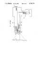
- FIG. 1is a block diagram of a configuration of an endoscope according to a first embodiment of the present invention
- FIGS. 2A to 2Cshow mechanisms for moving an illumination lens of the first embodiment along its optical axis
- FIGS. 3A and 3Bare views for explaining a change in the angle of view of the optical system when the illumination lens is moved along its optical axis;
- FIG. 4is a circuit diagram of an image enlargement controller according to the first embodiment of the present invention.
- FIGS. 5A to 5Care views for explaining image enlargement processing.
- FIG. 6is a block diagram of an endoscope according to a second embodiment of the present invention.
- FIG. 1is a block diagram of a configuration of the first embodiment.
- This embodimentexemplifies an electronic scope system wherein a solid-state image pickup element is incorporated in the distal end of an endoscope.
- the systemincludes endoscope main body 10, light source unit 12, and CRT monitor 14.
- Illumination optical system 18 for illuminating an object 17 in the body cavity, and objective optical system 16 for obtaining an optical image of object 17are provided in the distal end of main body 10.
- Illumination light from unit 12is transmitted to optical system 18 via light guide 20 comprising an optical fiber bundle.
- optical system 18comprises a zoom lens.
- Frame 22can be moved forward and backward by control section 11 of main body 10 through wire 24.
- An optical image of object 17 which is obtained by objective lens 16is picked up by solid-state image pickup element (CCD in this case) 26.
- CCDsolid-state image pickup element
- Unit 12has lamp 30 for emitting illumination light to be incident on light guide 20 in main body 10.
- the illumination light from lamp 30is colored by rotating color filter 32 to have red (R), green (G), and blue (B) light components sequentially for every one frame image pickup period of CCD 26. Therefore, object 17 is colored R, G, and B sequentially in one frame image pickup period of CCD 26.
- CCD 26picks up R, G, and B component images in one frame image pickup period to perform color image pickup in accordance with a sequential surface scheme.
- Filter 32includes a filter disc having R, G, and B regions arranged sequentially along its circumference, and is rotated by motor 33 in synchronism with the image pickup operation by CCD 26.
- R, G, and B picture image signals from CCD 26are sequentially input in video processor 34 in unit 12, are converted into parallel color image signals by video processor 34, and are supplied to image enlargement processor 36.
- Processor 36enlarges and displays the image on monitor 14 when the focal length of optical system 18 is varied to narrow the angle of view. The details of processor 36 is shown in FIG. 4.
- FIGS. 2A to 2Cshow mechanisms for moving frame 22 holding lens 18a along its optical path, i.e., a zoom mechanism of optical system 18. All of the mechanisms in FIGS. 2A to 2C move wire 24 to the right and left in the drawings.
- teethare provided on terminal member 42 of wire 24, and ring 40 engaged with the teeth is provided in control section 11 of main body 10. When ring 40 is rotated, the teeth of member 42 are engaged therewith, thereby moving wire 24 to the right or left.
- rack 44is connected to the end of wire 24.
- rack 44 and wire 24can be moved to the right or left. Wire 24 can also be moved to the right or left by the rotational movement of lever 47 in accordance with a link mechanism shown in FIG. 2C.
- a change in the illumination range of lens 18a in a case where it is moved along its optical axiswill be described.
- lens 18ais moved forward, as shown in FIG. 3A, the focal length of optical system 18 is shortened, the angle of view thereof is widened, and the illumination range (the hatched region in the drawing) is also widened.
- the focal length of optical system 18is elongated, the angle of view thereof is narrowed, and the illumination range is narrowed as well.
- the illumination rangeis narrowed, the light intensity per unit area of the object is increased, even if the amount of light transmitted through light guide 20 is the same.
- the illumination rangeis narrowed as shown in FIG. 3B so that the light intensity per unit area of the object is increased.
- FIG. 4is a block diagram showing image enlargement processor 36 of FIG. 1 in detail.
- An output signal from CCD 26is supplied to video processor 34 having sample/hold (SH) circuit 50, low pass filter (LPF) 52, and multiplexer 54.
- Multiplexer 54switches an output from LPF 52 to one of three output terminals for every one frame.
- CCD 26sequentially outputs R, G, and B image signals for every one frame.
- Multiplexer 54outputs the R, G, and B image signals to the first, second and third output terminals.
- the first, second, and third output signals (R, G, and B signal components) from multiplexer 54are written in frame memories 58a, 58b, and 58c via A/D converters 56a, 56b, and 56c, respectively.
- the image signals read out from frame memories 58a, 58b, and 58care then written in frame memories 62a, 62b, and 62c via digital filters 60a, 60b, and 60c, respectively. Subsequently, the image signals read out from frame memories 62a, 62b, and 62c are supplied to CRT monitor 14 as the R, G, and B signal components via D/A converters 64a, 64b, and 64c, and analog filters 66a, 66b, and 66c, respectively.
- Timing controller 68is connected to A/D converters 56a, 56b, and 56c, D/A converters 64a, 64b, and 64c, frame memories 58a, 58b, and 58c, and frame memories 62a, 62b, and 62c.
- a magnification data (Mg data) corresponding to the shifting amount of the moving mechanism of lens 18ais supplied to timing controller 68.
- Magnificationused here means the ratio of the size of the entire display screen of CRT monitor 14 to the illumination range, which is reduced by movement of lens 18a as shown in FIG. 3B.
- the operation of the first embodimentwill be described.
- the operatordirects the distal end of the inserting section of the main body 10 to the object 17.
- an object to be examineddoes not always coincide with the size of the display screen. If the object to be examined occupies only part of the display screen, it is enlarged and displayed.
- the operatorcontrols the angle of the distal end of the endoscope so that the object to be enlarged is located at the central portion of the display screen of CRT monitor 14.
- the illumination lightcovers the entire area of the image pickup range (image-pickup surface) of CCD 26.
- the operatormoves lens 18a backward as shown in FIG. 3B, and narrows the angle of view of optical system 18, and thus the illumination range, so that the illumination light illuminates only the object to be enlarged.
- the display screen of CRT monitor 14excluding the object to be enlarged becomes dark, the light intensity on the object is increased.
- An image signal picked up under this conditionis supplied to processor 36 through video processor 34, and is enlarged in the following manner.
- Timing controller 68supplies an A/D conversion timing signal to A/D converters 56a, 56b, and 56c, and a write signal (WR) to frame memories 58a, 58b, and 58c in accordance with the magnification signal, and writes only a predetermined portion of the image signal output from CCD 26 in frame memories 58a, 58b, and 58c.
- This enlargement processis shown in FIGS. 5A and 5B. Assume that 1/4 of the monitor screen at the central portion thereof is the object to be enlarged (object to be examined). As shown by a broken line in FIG. 5A, lens 18a is adjusted so that the circle around the object to be enlarged corresponds to the illumination range.
- the magnification signalis an enlargement magnification signal of x 2 in the vertical direction and x 2 in the horizontal direction.
- An image signal enlarged by x 2 in the horizontal direction as shown in FIG. 5Bis written in frame memories 58a, 58b, and 58c.
- the broken lines in FIG. 5Bdefine the horizontal x 2 enlarged region corresponding to the central portion in FIG. 5A.
- controller 68supplies a read signal (RD) to frame memories 58a, 58b, and 58c, and a write signal (WR) to frame memories 62a, 62b, and 62c in accordance with the magnification signal, thereby changing the magnification of the image signals.
- RDread signal
- WRwrite signal
- the images in memories 58a, 58b, and 58care enlarged by x 2 in the vertical direction, as shown in FIG. 5C.
- the image of the inner rectangular region of FIG. 5A read out from CCD 26is enlarged in accordance with the magnification signal and is displayed on the entire surface of the display screen of CRT monitor 14.
- the spot diameter of the illumination lightis changed in accordance with the size of the object to be examined, which is displayed on the screen, so that the light intensity on the object can be increased.
- the objectis enlarged to cover the entire surface of the display screen. Since the image is enlarged by signal processing using the frame memories, the configuration of the entire system can be simple and can easily cope with the change in the magnification.
- FIG. 6is a block diagram of a second embodiment of the present invention.
- the second embodimentis applied to a conventional fiber scope, not an electronic scope.
- image guide 70comprising an optical fiber bundle, like light guide 20 of the first embodiment, is provided in place of CCD 26.
- An optical image obtained by objective optical system 16is transmitted to ocular 72 at the rear end of endoscope control section 11 via image guide 70.
- the object to be examinedis observed by a human eye on the basis of the optical image transmitted to ocular 72.
- the size of the angle of viewis changed in the same manner as in the first embodiment and the object to be examined can be observed with a constantly sufficient light intensity by changing the angle of view of the illumination light.
- the present inventionis not limited to the embodiments described above, and various modifications can be made within the spirit and scope of the invention.
- the light sourceis provided outside the endoscope main body.
- the present inventioncan be applied to an endoscope wherein a light source lamp is incorporated in the distal end of an inserting section.
- the illumination light from the light source lampilluminates the object through an illumination optical system having a zoom lens.
- the image enlargement processing in the electronic scope systemis not limited to the first embodiment.
- the focal length of an illumination optical system provided on the distal end of the inserting section of the endoscopei.e., an angle of view
- the illumination lightilluminates only an object to be examined within the field of view. Therefore, the intensity of the illumination light can be increased without increasing the diameter of the inserting section or causing adverse effects due to heat generation, thereby providing an endoscope which can observe an object under sufficient light intensity.
Landscapes
- Physics & Mathematics (AREA)
- Life Sciences & Earth Sciences (AREA)
- Health & Medical Sciences (AREA)
- Surgery (AREA)
- Optics & Photonics (AREA)
- Engineering & Computer Science (AREA)
- Heart & Thoracic Surgery (AREA)
- Medical Informatics (AREA)
- Biophysics (AREA)
- Nuclear Medicine, Radiotherapy & Molecular Imaging (AREA)
- Pathology (AREA)
- Radiology & Medical Imaging (AREA)
- Veterinary Medicine (AREA)
- Biomedical Technology (AREA)
- General Physics & Mathematics (AREA)
- Public Health (AREA)
- Molecular Biology (AREA)
- Animal Behavior & Ethology (AREA)
- General Health & Medical Sciences (AREA)
- Astronomy & Astrophysics (AREA)
- Multimedia (AREA)
- Signal Processing (AREA)
- Endoscopes (AREA)
- Instruments For Viewing The Inside Of Hollow Bodies (AREA)
Abstract
Description
Claims (11)
Applications Claiming Priority (2)
| Application Number | Priority Date | Filing Date | Title |
|---|---|---|---|
| JP60153573AJPH0658458B2 (en) | 1985-07-12 | 1985-07-12 | Endoscope device |
| JP60-153573 | 1985-07-12 |
Publications (1)
| Publication Number | Publication Date |
|---|---|
| US4736734Atrue US4736734A (en) | 1988-04-12 |
Family
ID=15565445
Family Applications (1)
| Application Number | Title | Priority Date | Filing Date |
|---|---|---|---|
| US06/881,816Expired - LifetimeUS4736734A (en) | 1985-07-12 | 1986-07-03 | Endoscope with variable illumination angle |
Country Status (3)
| Country | Link |
|---|---|
| US (1) | US4736734A (en) |
| JP (1) | JPH0658458B2 (en) |
| DE (1) | DE3623114A1 (en) |
Cited By (31)
| Publication number | Priority date | Publication date | Assignee | Title |
|---|---|---|---|---|
| US4871229A (en)* | 1987-11-11 | 1989-10-03 | Olympus Optical Co., Ltd. | Method for assembling optical fiber bundles in an endoscope |
| US4872740A (en)* | 1987-02-12 | 1989-10-10 | Mitsubishi Rayon Company, Ltd. | Endoscope |
| US4983019A (en)* | 1987-05-06 | 1991-01-08 | Olympus Optical Co., Ltd. | Endoscope light source apparatus |
| US5313936A (en)* | 1992-04-20 | 1994-05-24 | Olympus Optical Co., Ltd. | Industrial endoscope apparatus |
| US5456245A (en)* | 1993-09-20 | 1995-10-10 | Sofamor Danek Properties, Inc. | Flexible endoscope probe and method of manufacture |
| EP0682451A2 (en) | 1994-05-13 | 1995-11-15 | Precision Optics Corporation | Viewing scope with image intensification |
| US5575757A (en)* | 1992-10-09 | 1996-11-19 | Smith & Nephew Endoscopy Inc. | Endoscope with focusing mechanism |
| US5754719A (en)* | 1996-11-22 | 1998-05-19 | Cogent Light Technologies, Inc. | Method for coupling light from single fiberoptic to a multi-fiber bundle with enhanced field uniformity and better coupling efficiency |
| US5800344A (en)* | 1996-10-23 | 1998-09-01 | Welch Allyn, Inc. | Video laryngoscope |
| US5879289A (en)* | 1996-07-15 | 1999-03-09 | Universal Technologies International, Inc. | Hand-held portable endoscopic camera |
| US6016440A (en)* | 1996-07-29 | 2000-01-18 | Bruker Analytik Gmbh | Device for infrared (IR) spectroscopic investigations of internal surfaces of a body |
| US6432046B1 (en)* | 1996-07-15 | 2002-08-13 | Universal Technologies International, Inc. | Hand-held, portable camera for producing video images of an object |
| US20020159728A1 (en)* | 2001-04-27 | 2002-10-31 | Katsuhiro Kobayashi | Image fiber imaging apparatus |
| US20030009086A1 (en)* | 2001-06-01 | 2003-01-09 | Black Michael D. | Non-tethered macro-to-micro endoscope |
| US6554765B1 (en) | 1996-07-15 | 2003-04-29 | East Giant Limited | Hand held, portable camera with adaptable lens system |
| US20030130562A1 (en)* | 2002-01-09 | 2003-07-10 | Scimed Life Systems, Inc. | Imaging device and related methods |
| US6840903B2 (en) | 2002-03-21 | 2005-01-11 | Nuvista Technology Corporation | Laryngoscope with image sensor |
| US6882875B1 (en) | 1997-09-29 | 2005-04-19 | Boston Scientific Corporation | Visible display for an interventional device |
| EP1619532A1 (en)* | 2004-07-21 | 2006-01-25 | J.M. Canty Inc. | Inspection device for inspecting fluid in a vessel |
| US20070055106A1 (en)* | 2004-04-27 | 2007-03-08 | Hiroki Moriyama | Endoscope and endoscope system |
| US20070156021A1 (en)* | 2005-09-14 | 2007-07-05 | Bradford Morse | Remote imaging apparatus having an adaptive lens |
| US20070179342A1 (en)* | 2006-01-12 | 2007-08-02 | Kb Port Llc | Wireless Laryngoscope with Internal Antennae and One Piece Construction Adapted for Laryngoscopy Training |
| US20080198482A1 (en)* | 2004-08-16 | 2008-08-21 | Xceed Imaging Ltd. | Optical Method and System for Extended Depth of Focus |
| US20110194195A1 (en)* | 2010-02-09 | 2011-08-11 | Zeev Zalevsky | Optical apparatus with structure for liquid invariant performance |
| EP2505120A3 (en)* | 2011-03-28 | 2013-02-27 | Fujifilm Corporation | Endoscope and lighting optical device therefor |
| US20150257630A1 (en)* | 2013-05-22 | 2015-09-17 | Olympus Corporation | Endoscope |
| US9622651B2 (en) | 2012-01-27 | 2017-04-18 | Kbport Llc | Wireless laryngoscope simulator with onboard event recording adapted for laryngoscopy training |
| US20190121118A1 (en)* | 2010-10-28 | 2019-04-25 | Endochoice Innovation Center Ltd. | Optical systems for multi-sensor endoscopes |
| US11213191B2 (en) | 2018-01-25 | 2022-01-04 | Canon U.S.A., Inc. | Optical fiber arrangement for endoscope |
| US20230112879A1 (en)* | 2020-03-03 | 2023-04-13 | Richard Wolf Gmbh | Medical endoscopic instrument |
| US12204087B2 (en)* | 2010-10-28 | 2025-01-21 | Endochoice, Inc. | Optical systems for multi-sensor endoscopes |
Families Citing this family (8)
| Publication number | Priority date | Publication date | Assignee | Title |
|---|---|---|---|---|
| JPS63176406U (en)* | 1987-05-06 | 1988-11-16 | ||
| JPH0627714B2 (en)* | 1988-05-20 | 1994-04-13 | ヤシマ工業株式会社 | Device for diagnosing adhesion state of fine fibrous material layer |
| US4905670A (en)* | 1988-12-28 | 1990-03-06 | Adair Edwin Lloyd | Apparatus for cervical videoscopy |
| DE4102614C2 (en)* | 1991-01-30 | 1996-08-29 | Dornier Medizintechnik | Endoscope for inspecting body cavities, especially for tumor detection |
| DE4420599A1 (en)* | 1994-06-13 | 1995-12-14 | Siemens Ag | Device for examining tissue in vivo |
| US7314300B1 (en)* | 2005-04-29 | 2008-01-01 | Sunoptic Technologies Llc | Fiber optic surgical headlight system |
| JP2017086788A (en)* | 2015-11-17 | 2017-05-25 | Hoya株式会社 | Light source device |
| JP6943246B2 (en) | 2016-08-08 | 2021-09-29 | ソニーグループ株式会社 | Endoscope device and control method of the endoscope device |
Citations (5)
| Publication number | Priority date | Publication date | Assignee | Title |
|---|---|---|---|---|
| US3090378A (en)* | 1960-05-16 | 1963-05-21 | Bausch & Lomb | Focusing endoscope |
| US3178994A (en)* | 1961-03-31 | 1965-04-20 | John W Lang | Borescope |
| US4076018A (en)* | 1974-12-06 | 1978-02-28 | Richard Wolf Gmbh | Endoscopes |
| US4390012A (en)* | 1979-04-17 | 1983-06-28 | Olympus Optical Co., Ltd. | Rigid type endoscope |
| US4452236A (en)* | 1981-05-14 | 1984-06-05 | Olympus Optical Co., Ltd. | Endoscope with a resilient raising member |
Family Cites Families (9)
| Publication number | Priority date | Publication date | Assignee | Title |
|---|---|---|---|---|
| US3091235A (en)* | 1960-06-15 | 1963-05-28 | American Optical Corp | Diagnostic instruments |
| US3473140A (en)* | 1966-08-12 | 1969-10-14 | Ericsson Telefon Ab L M | Filter circuit with reciprocal impedance branches |
| JPS5675907U (en)* | 1979-11-15 | 1981-06-20 | ||
| JPS5675909U (en)* | 1979-11-15 | 1981-06-20 | ||
| DE2948447A1 (en)* | 1979-12-01 | 1981-06-04 | OEB Optik-Elektronik-Bau Helmut Hund KG, 6330 Wetzlar | Size variation for lighted spot - uses fixed optical system with axially adjustable or variable-focus second system |
| JPS56165111A (en)* | 1980-05-26 | 1981-12-18 | Nippon Kogaku Kk <Nikon> | Telecentric illuminating system |
| JPS5887525A (en)* | 1981-11-19 | 1983-05-25 | Olympus Optical Co Ltd | Illuminating optical system for endoscope |
| DE3211187A1 (en)* | 1982-03-26 | 1983-09-29 | Fa. Carl Zeiss, 7920 Heidenheim | DEVICE FOR SHARP LIGHTING OF AN OBSERVATION FIELD LOCATED IN A SELECTABLE LEVEL |
| DE3436057C2 (en)* | 1983-10-03 | 1985-12-12 | Olympus Optical Co., Ltd., Tokio/Tokyo | Endoscope with a solid receiving element |
- 1985
- 1985-07-12JPJP60153573Apatent/JPH0658458B2/ennot_activeExpired - Lifetime
- 1986
- 1986-07-03USUS06/881,816patent/US4736734A/ennot_activeExpired - Lifetime
- 1986-07-09DEDE19863623114patent/DE3623114A1/enactiveGranted
Patent Citations (5)
| Publication number | Priority date | Publication date | Assignee | Title |
|---|---|---|---|---|
| US3090378A (en)* | 1960-05-16 | 1963-05-21 | Bausch & Lomb | Focusing endoscope |
| US3178994A (en)* | 1961-03-31 | 1965-04-20 | John W Lang | Borescope |
| US4076018A (en)* | 1974-12-06 | 1978-02-28 | Richard Wolf Gmbh | Endoscopes |
| US4390012A (en)* | 1979-04-17 | 1983-06-28 | Olympus Optical Co., Ltd. | Rigid type endoscope |
| US4452236A (en)* | 1981-05-14 | 1984-06-05 | Olympus Optical Co., Ltd. | Endoscope with a resilient raising member |
Cited By (65)
| Publication number | Priority date | Publication date | Assignee | Title |
|---|---|---|---|---|
| US4872740A (en)* | 1987-02-12 | 1989-10-10 | Mitsubishi Rayon Company, Ltd. | Endoscope |
| US4983019A (en)* | 1987-05-06 | 1991-01-08 | Olympus Optical Co., Ltd. | Endoscope light source apparatus |
| US4871229A (en)* | 1987-11-11 | 1989-10-03 | Olympus Optical Co., Ltd. | Method for assembling optical fiber bundles in an endoscope |
| US5313936A (en)* | 1992-04-20 | 1994-05-24 | Olympus Optical Co., Ltd. | Industrial endoscope apparatus |
| US5575757A (en)* | 1992-10-09 | 1996-11-19 | Smith & Nephew Endoscopy Inc. | Endoscope with focusing mechanism |
| US5456245A (en)* | 1993-09-20 | 1995-10-10 | Sofamor Danek Properties, Inc. | Flexible endoscope probe and method of manufacture |
| EP0682451A2 (en) | 1994-05-13 | 1995-11-15 | Precision Optics Corporation | Viewing scope with image intensification |
| US5733246A (en)* | 1994-05-13 | 1998-03-31 | Precision Optics Corporation | Viewing scope with image intensification |
| US6432046B1 (en)* | 1996-07-15 | 2002-08-13 | Universal Technologies International, Inc. | Hand-held, portable camera for producing video images of an object |
| US5879289A (en)* | 1996-07-15 | 1999-03-09 | Universal Technologies International, Inc. | Hand-held portable endoscopic camera |
| US6554765B1 (en) | 1996-07-15 | 2003-04-29 | East Giant Limited | Hand held, portable camera with adaptable lens system |
| US6692432B1 (en) | 1996-07-15 | 2004-02-17 | East Giant Limited | Hand-held portable camera for producing video images of an object |
| US6016440A (en)* | 1996-07-29 | 2000-01-18 | Bruker Analytik Gmbh | Device for infrared (IR) spectroscopic investigations of internal surfaces of a body |
| US5800344A (en)* | 1996-10-23 | 1998-09-01 | Welch Allyn, Inc. | Video laryngoscope |
| US5754719A (en)* | 1996-11-22 | 1998-05-19 | Cogent Light Technologies, Inc. | Method for coupling light from single fiberoptic to a multi-fiber bundle with enhanced field uniformity and better coupling efficiency |
| US6882875B1 (en) | 1997-09-29 | 2005-04-19 | Boston Scientific Corporation | Visible display for an interventional device |
| US6744957B2 (en)* | 2001-04-27 | 2004-06-01 | Matsushita Electric Industrial Co., Ltd. | Image fiber imaging apparatus |
| US20020159728A1 (en)* | 2001-04-27 | 2002-10-31 | Katsuhiro Kobayashi | Image fiber imaging apparatus |
| US20030009086A1 (en)* | 2001-06-01 | 2003-01-09 | Black Michael D. | Non-tethered macro-to-micro endoscope |
| US6869397B2 (en)* | 2001-06-01 | 2005-03-22 | The Board Of Trustees Of The Leland Stanford Junior University | Non-tethered macro-to-micro endoscope |
| US20030130562A1 (en)* | 2002-01-09 | 2003-07-10 | Scimed Life Systems, Inc. | Imaging device and related methods |
| US8423110B2 (en) | 2002-01-09 | 2013-04-16 | Boston Scientific Scimed, Inc. | Imaging device and related methods |
| US6840903B2 (en) | 2002-03-21 | 2005-01-11 | Nuvista Technology Corporation | Laryngoscope with image sensor |
| US20050043590A1 (en)* | 2002-03-21 | 2005-02-24 | Mazzei William J. | Laryngoscope with image sensor |
| WO2003101280A3 (en)* | 2002-05-31 | 2004-07-08 | Univ Leland Stanford Junior | A non-tethered macro-to-micro endoscope |
| US20070055106A1 (en)* | 2004-04-27 | 2007-03-08 | Hiroki Moriyama | Endoscope and endoscope system |
| US8002697B2 (en)* | 2004-04-27 | 2011-08-23 | Olympus Corporation | Dual endoscope system with display unit |
| EP1619532A1 (en)* | 2004-07-21 | 2006-01-25 | J.M. Canty Inc. | Inspection device for inspecting fluid in a vessel |
| US20060017930A1 (en)* | 2004-07-21 | 2006-01-26 | J.M. Canty Inc. | Insertion fluid inspection device |
| US7193702B2 (en) | 2004-07-21 | 2007-03-20 | J.M. Canty Inc. | Insertion fluid inspection device |
| US20110082541A1 (en)* | 2004-08-16 | 2011-04-07 | Xceed Imaging Ltd. | Optical method and system for extended depth of focus |
| US8192022B2 (en) | 2004-08-16 | 2012-06-05 | Xceed Imaging Ltd. | Optical method and system for extended depth of focus |
| US20080198482A1 (en)* | 2004-08-16 | 2008-08-21 | Xceed Imaging Ltd. | Optical Method and System for Extended Depth of Focus |
| US7859769B2 (en)* | 2004-08-16 | 2010-12-28 | Xceed Imaging Ltd. | Optical method and system for extended depth of focus |
| US20070156021A1 (en)* | 2005-09-14 | 2007-07-05 | Bradford Morse | Remote imaging apparatus having an adaptive lens |
| US20070179342A1 (en)* | 2006-01-12 | 2007-08-02 | Kb Port Llc | Wireless Laryngoscope with Internal Antennae and One Piece Construction Adapted for Laryngoscopy Training |
| US9500875B2 (en) | 2010-02-09 | 2016-11-22 | Brien Holden Vision Institute | Imaging with extended depth of focus for use with polycromatic light |
| US12313916B2 (en) | 2010-02-09 | 2025-05-27 | Brien Holden Vision Institute Limited | Optical apparatus with structure for liquid invariant performance |
| US11802997B2 (en) | 2010-02-09 | 2023-10-31 | Brien Holden Vision Institute Limited | Optical apparatus with structure for liquid invariant performance |
| US20110194180A1 (en)* | 2010-02-09 | 2011-08-11 | Xceed Imaging Ltd. | Imaging Method and system for Imaging with Extended depth of Focus |
| US8531783B2 (en) | 2010-02-09 | 2013-09-10 | Xceed Imaging Ltd. | Imaging method and system for imaging with extended depth of focus |
| US8913331B2 (en) | 2010-02-09 | 2014-12-16 | Brien Holden Vision Institute | Imaging method and system with optimized extended depth of focus |
| US8955968B2 (en) | 2010-02-09 | 2015-02-17 | Brien Holden Vision Institute | Imaging with extended depth of focus for use with polychromatic light |
| US9134543B2 (en) | 2010-02-09 | 2015-09-15 | Brien Holden Vision Institute | Imaging system with optimized extended depth of focus |
| US8169716B2 (en) | 2010-02-09 | 2012-05-01 | Xceed Imaging, Ltd. | Optical apparatus with structure for liquid invariant performance |
| US9239471B2 (en) | 2010-02-09 | 2016-01-19 | Brien Holden Vision Institute | Multi-focal lens |
| US9429768B2 (en) | 2010-02-09 | 2016-08-30 | Brien Holden Vision Institute | Imaging method and system with optimized extended depth of focus |
| US20110194195A1 (en)* | 2010-02-09 | 2011-08-11 | Zeev Zalevsky | Optical apparatus with structure for liquid invariant performance |
| US11802998B2 (en) | 2010-02-09 | 2023-10-31 | Brien Holden Vision Institute Limited | Imaging system with optimized extended depth of focus |
| US12259565B2 (en) | 2010-02-09 | 2025-03-25 | Brien Holden Vision Institute Limited | Imaging system with optimized extended depth of focus |
| US10031334B2 (en) | 2010-02-09 | 2018-07-24 | Brien Holden Vision Institute | Optical apparatus with structure for liquid invariant performance |
| US10078159B2 (en) | 2010-02-09 | 2018-09-18 | Brien Holden Vision Institute | Multi-focal lens |
| US10175392B2 (en) | 2010-02-09 | 2019-01-08 | Brien Holden Vision Institute | Imaging system with optimized extended depth of focus |
| US12282175B2 (en) | 2010-02-09 | 2025-04-22 | Brien Holden Vision Institute Limited | Multi-focal lens |
| US11079517B2 (en) | 2010-02-09 | 2021-08-03 | Brien Holden Vision Institute Limited | Optical apparatus with structure for liquid invariant performance |
| US11199651B2 (en) | 2010-02-09 | 2021-12-14 | Brien Holden Vision Institute Limited | Imaging system with optimized extended depth of focus |
| US20190121118A1 (en)* | 2010-10-28 | 2019-04-25 | Endochoice Innovation Center Ltd. | Optical systems for multi-sensor endoscopes |
| US11543646B2 (en)* | 2010-10-28 | 2023-01-03 | Endochoice, Inc. | Optical systems for multi-sensor endoscopes |
| US12204087B2 (en)* | 2010-10-28 | 2025-01-21 | Endochoice, Inc. | Optical systems for multi-sensor endoscopes |
| EP2505120A3 (en)* | 2011-03-28 | 2013-02-27 | Fujifilm Corporation | Endoscope and lighting optical device therefor |
| US9622651B2 (en) | 2012-01-27 | 2017-04-18 | Kbport Llc | Wireless laryngoscope simulator with onboard event recording adapted for laryngoscopy training |
| US20150257630A1 (en)* | 2013-05-22 | 2015-09-17 | Olympus Corporation | Endoscope |
| US9808141B2 (en)* | 2013-05-22 | 2017-11-07 | Olympus Corporation | Endoscope |
| US11213191B2 (en) | 2018-01-25 | 2022-01-04 | Canon U.S.A., Inc. | Optical fiber arrangement for endoscope |
| US20230112879A1 (en)* | 2020-03-03 | 2023-04-13 | Richard Wolf Gmbh | Medical endoscopic instrument |
Also Published As
| Publication number | Publication date |
|---|---|
| DE3623114A1 (en) | 1987-01-22 |
| JPS6214614A (en) | 1987-01-23 |
| DE3623114C2 (en) | 1989-07-27 |
| JPH0658458B2 (en) | 1994-08-03 |
Similar Documents
| Publication | Publication Date | Title |
|---|---|---|
| US4736734A (en) | Endoscope with variable illumination angle | |
| US4951135A (en) | Electronic-type endoscope system having capability of setting AGC variation region | |
| US5430475A (en) | Electronic endoscope apparatus having micro array on photoelectric conversion surface | |
| US4890159A (en) | Endoscope system and method of unifying picture images in an endoscope system | |
| US4639772A (en) | Focusable video camera for use with endoscopes | |
| EP0172680A1 (en) | Sequential colour light sources for endoscopes of the type employing a solid-state imaging device | |
| US20080143826A1 (en) | Image-signal transmission system, electronic endoscope, and endoscope processor | |
| JP3645055B2 (en) | Video scope | |
| JPH0894942A (en) | Light source device | |
| US4600938A (en) | Focusable video camera for use with endoscopes | |
| JPS6054589A (en) | Illuminating and image pickup device for color video | |
| JPS61177421A (en) | Light source device for endoscope | |
| JP2874305B2 (en) | Electronic endoscope device | |
| JP3047831U (en) | Digital optical microscope and telescope | |
| JP2715383B2 (en) | Endoscope device | |
| JP2897920B2 (en) | Endoscope system | |
| JPH0625827B2 (en) | Light source optical system for endoscope | |
| JPS6199484A (en) | Endoscope | |
| JP2837896B2 (en) | External TV camera for endoscope | |
| JP2843328B2 (en) | Electronic endoscope device | |
| JPS6141431A (en) | Iris apparatus of light source apparatus for endoscope | |
| JP2624993B2 (en) | Light source device for endoscope | |
| JP2598401B2 (en) | Endoscope imaging device | |
| JP2981437B2 (en) | Light source device for endoscope | |
| JPH0542647B2 (en) |
Legal Events
| Date | Code | Title | Description |
|---|---|---|---|
| AS | Assignment | Owner name:OLYMPUS OPTICAL CO., LTD., 43-2, 2-CHOME, HATAGAYA Free format text:ASSIGNMENT OF ASSIGNORS INTEREST.;ASSIGNORS:MATSUURA, NOBUYUKI;KANNO, MASAHIDE;TAKEUCHI, HARUO;AND OTHERS;REEL/FRAME:004606/0797 Effective date:19860624 Owner name:OLYMPUS OPTICAL CO., LTD., 43-2, 2-CHOME, HATAGAYA Free format text:ASSIGNMENT OF ASSIGNORS INTEREST;ASSIGNORS:MATSUURA, NOBUYUKI;KANNO, MASAHIDE;TAKEUCHI, HARUO;AND OTHERS;REEL/FRAME:004606/0797 Effective date:19860624 | |
| STCF | Information on status: patent grant | Free format text:PATENTED CASE | |
| FEPP | Fee payment procedure | Free format text:PAYOR NUMBER ASSIGNED (ORIGINAL EVENT CODE: ASPN); ENTITY STATUS OF PATENT OWNER: LARGE ENTITY | |
| FPAY | Fee payment | Year of fee payment:4 | |
| FEPP | Fee payment procedure | Free format text:PAYOR NUMBER ASSIGNED (ORIGINAL EVENT CODE: ASPN); ENTITY STATUS OF PATENT OWNER: LARGE ENTITY Free format text:PAYER NUMBER DE-ASSIGNED (ORIGINAL EVENT CODE: RMPN); ENTITY STATUS OF PATENT OWNER: LARGE ENTITY | |
| FPAY | Fee payment | Year of fee payment:8 | |
| FPAY | Fee payment | Year of fee payment:12 |