US4736645A - Gear unit for a manipulator - Google Patents
Gear unit for a manipulatorDownload PDFInfo
- Publication number
- US4736645A US4736645AUS06/888,146US88814686AUS4736645AUS 4736645 AUS4736645 AUS 4736645AUS 88814686 AUS88814686 AUS 88814686AUS 4736645 AUS4736645 AUS 4736645A
- Authority
- US
- United States
- Prior art keywords
- segment
- gear
- axis
- head unit
- drive shaft
- Prior art date
- Legal status (The legal status is an assumption and is not a legal conclusion. Google has not performed a legal analysis and makes no representation as to the accuracy of the status listed.)
- Expired - Lifetime
Links
- 230000009467reductionEffects0.000claimsabstractdescription28
- 230000001154acute effectEffects0.000claimsdescription7
- 230000033001locomotionEffects0.000abstractdescription14
- 230000009471actionEffects0.000abstractdescription2
- 230000000694effectsEffects0.000description2
- 241001416181Axis axisSpecies0.000description1
- 230000005540biological transmissionEffects0.000description1
- 230000008859changeEffects0.000description1
- 238000004590computer programMethods0.000description1
- 239000004020conductorSubstances0.000description1
- 238000010276constructionMethods0.000description1
- 230000008878couplingEffects0.000description1
- 238000010168coupling processMethods0.000description1
- 238000005859coupling reactionMethods0.000description1
- 238000006073displacement reactionMethods0.000description1
- 230000006872improvementEffects0.000description1
- 238000000034methodMethods0.000description1
- 230000008569processEffects0.000description1
- 238000005096rolling processMethods0.000description1
Images


Classifications
- F—MECHANICAL ENGINEERING; LIGHTING; HEATING; WEAPONS; BLASTING
- F16—ENGINEERING ELEMENTS AND UNITS; GENERAL MEASURES FOR PRODUCING AND MAINTAINING EFFECTIVE FUNCTIONING OF MACHINES OR INSTALLATIONS; THERMAL INSULATION IN GENERAL
- F16H—GEARING
- F16H1/00—Toothed gearings for conveying rotary motion
- F16H1/02—Toothed gearings for conveying rotary motion without gears having orbital motion
- F16H1/20—Toothed gearings for conveying rotary motion without gears having orbital motion involving more than two intermeshing members
- B—PERFORMING OPERATIONS; TRANSPORTING
- B25—HAND TOOLS; PORTABLE POWER-DRIVEN TOOLS; MANIPULATORS
- B25J—MANIPULATORS; CHAMBERS PROVIDED WITH MANIPULATION DEVICES
- B25J17/00—Joints
- B25J17/02—Wrist joints
- B25J17/0283—Three-dimensional joints
- B25J17/0291—Three-dimensional joints having axes crossing at an oblique angle, i.e. other than 90 degrees
- B—PERFORMING OPERATIONS; TRANSPORTING
- B25—HAND TOOLS; PORTABLE POWER-DRIVEN TOOLS; MANIPULATORS
- B25J—MANIPULATORS; CHAMBERS PROVIDED WITH MANIPULATION DEVICES
- B25J9/00—Programme-controlled manipulators
- Y—GENERAL TAGGING OF NEW TECHNOLOGICAL DEVELOPMENTS; GENERAL TAGGING OF CROSS-SECTIONAL TECHNOLOGIES SPANNING OVER SEVERAL SECTIONS OF THE IPC; TECHNICAL SUBJECTS COVERED BY FORMER USPC CROSS-REFERENCE ART COLLECTIONS [XRACs] AND DIGESTS
- Y10—TECHNICAL SUBJECTS COVERED BY FORMER USPC
- Y10T—TECHNICAL SUBJECTS COVERED BY FORMER US CLASSIFICATION
- Y10T74/00—Machine element or mechanism
- Y10T74/19—Gearing
- Y10T74/19642—Directly cooperating gears
- Y10T74/1966—Intersecting axes
- Y10T74/19665—Bevel gear type
Definitions
- My present inventionrelates to a gear unit for a manipulator, e.g. an arm of an industrial robot.
- a gear unit for a manipulatorcan comprise three segments mounted following each other and pivotable together with respect to each other about first and second inclined pivot axes with three drive shafts mounted concentric to each other, of which intermediate drive shafts are journaled along the first and second inclined pivot axes and which can have reduction gears associated with their output or driven side.
- the first and second inclined pivot axesform acute angles with the longitudinal axis of the manipulator arm, being inclined in opposite directions in the extended configuration of the arm.
- German printed patent application DE-AS No. 27 45 932described a gear unit for a manipulator having two segments mounted following each other which are pivotally mounted in planes inclined to each other.
- the tool holder on the rear gear segmentis rotatably mounted on a pivot axis coaxial with the main drive shaft axis of the manipulator.
- gear unit segments connected in cascadecomprise the gear head unit for the manipulator.
- the intermediate or middle gear-head segmenthas two inclined pivot axes which form acute angles with the longitudinal axis of the gear head unit inclined in opposite directions.
- At the end of the intermediate gear shaft leading to this gear-head segmentat least one large reduction gearing unit is mounted.
- this gear-head unithas a substantially larger motion play in a compact structure.
- an essentially larger operating range for the tool held by the manipulatoris attained. Since, in this case, the output drive shaft is not coaxial with the main drive shaft the ambiguity in the calculational control is avoided.
- a gear-head unit for a manipulatorcomprising three gear segments mounted following each other and pivotable together with respect to each other about first and second inclined pivot axes having three drive shafts mounted concentrically whose gear-head unit driving members extend along the first and second inclined pivot axes to the gear-head segment to be driven and which have reduction gears associated with their output or driven sides.
- the first and second inclined pivot axesform acute angles with the longitudinal axis of the manipulator inclined in opposite directions in the extended configuration of the arm.
- a drive unitcomprising an output drive shaft, a reduction gear supported in the rear segment and a rotatably mounted front plate for a tool holder driven by the output drive shaft is mounted in the rear segment, and the gear-head unit driving members leading to the intermediate segment and to the rear segment comprise front and rear hollow drive shafts connected by a pair of second intermediate bevel gears through which two coupled intermediate drive shafts provided for driving the front plate extend.
- My inventionis able to perform four different rotational motions with three drive shafts positioned concentrically to each other, namely the rotation of the front gear-head segment about a main drive shaft axis, the rotation of the intermediate segment about the first inclined pivot axis with respect to the front gear segment, the rotation of the rear gear-head segment about the second inclined pivot axis with respect to the intermediate gear-head segment and the rotation of the tool holder in the rear gear segment.
- My inventionuses a first and second hollow drive shaft which extend along both of the inclined first and second pivot axes and are connected to each other by bevel gears and are driven by a single drive motor. Since these hollow shafts are supported by reduction gears in the front and/or intermediate segments, wherein the gears of the reduction gears are equal sized, and since the segments are mounted following each other, the rotation of the hollow drive shafts leads to a simultaneous but opposite rotation (or rotational moment) of the rear and intermediate segment about their inclined pivot axes. As a consequence these hollow shaft structures can provide a gear-head unit driving member to guide a drive shaft passing through the hollow shafts up to the final driven segment which is attached to the tool holder.
- a gear-head unit also having three segmentsis taught in German Open Patent Application No. 34 31 033 which has an output drive shaft attached to a tool holder driven by a coaxial main drive shaft.
- an output shaft axis of the output drive shaftcan be positioned inclined to the main drive shaft axis, acute angles of both first and second inclined pivot axes with the main drive shaft axis in the intermediate segment can be unequal, or in an inclined arrangement the output shaft axis of the output drive shaft intersects the point of intersection of both first and second inclined pivot axes.
- At least one of the first and second inclined pivot axes in the intermediate segmentcan be positioned in a plane which is inclined with respect to a longitudinal cross sectional plane of the manipulator. In one configuration extending from the longitudinal cross sectional plane the point of intersection of both first and second inclined pivot axes lies in the intermediate segment in the longitudinal cross sectional plane.
- intersection point of the inclined first and second pivot axes with the main drive shaft axis and the output shaft axiscan in one embodiment be provided as the central point of a ball or universal joint.
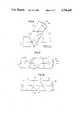
- FIG. 1is a diagrammatic side view of the gear-head unit for a manipulator showing the relationship of the various components of the gear-head unit and their axes of rotation in its extended position;
- FIG. 2is a diagrammatic side view of the apparatus according to FIG. 1 with a power take off inclined to the main drive shaft axis;
- FIGS. 3 and 4are side views of the gear-head unit of FIG. 1 in corresponding similar pivoted positions;
- FIGS. 5 to 11are side views of different embodiments of the gear-head unit for a manipulator according to my invention with rotation axes for their components inclined to the main drive shaft and arranged in different ways;
- FIGS. 12 to 14are longitudinal cross sectional views through three different embodiments of a gear-head unit for a manipulator according to my invention.
- the gear-head unit illustrated in FIG. 1 herecorresponds to that of FIG. 1 of German Open Patent Application No. 34 28 748 and shows that an ambiguity for automatic control exists when a front plate 38 and/or tool holder in the rear segment 3 of the gear-head unit is mounted so that it is pivotable about an output shaft axis 46 coaxial to main drive shaft axis 4 and is rotated. Then the rotation of the tool about the output shaft axis 46 could also be possible by rotation of the front segment 1 of the gear-head unit about the main drive shaft axis 4. This ambiguity could be avoided only in cases where the front segment 1 can be nonrotatably mounted about the main drive shaft axis 4.
- Intermediate segment 2 of the gear-head unitcan rotate about inclined pivot axis 5 with respect to front segment 1 and about inclined pivot axis 6 with respect to rear segment 3.
- FIG. 2shows one way to avoid the abovementioned ambiguity.
- the output shaft axis 46is inclined at an acute angle to the main drive shaft axis 4.
- the output shaft axis 46intersects both inclined axes 5 and 6 at the point of intersection 9 in order to make easy the computer control of the motion process.
- a pair of rear bevel gears 33 and 34drive the front plate 38. Should a rotation of the front plate 38 or tool holder about the output shaft axis 46 occur, the drive for the front segment is not enabled. Thus ambiguity is avoided.
- FIGS. 3 and 4here correspond to the FIGS. 2 and 4 of German Open Patent Application DE No. 3428 748.
- the rear segment 3is pivotable about an angle (2 ⁇ ) with respect to the main drive shaft axis 4.
- Different rotational drivescan be used.
- the rear segment 3is rotatable about 180° with respect to the fixed intermediate segment 2.
- the intermediate segment 2is rotatable about 180° with respect to the front segment 1 while the rear segment 3 remains in the same position on it.
- the angle ( ⁇ 1 ) and the angle ⁇ 2 ) of the inclined axes 5 and 6are not the same size so that the point of intersection 9 is displaced laterally from the symmetric position shown in FIG. 1.
- the same rotations of the intermediate and rear segments 2 and 3lead to different angular configurations of the manipulator.
- the inclined pivot axis 5is inclined to the plane of the drawing so that the point of intersection 9 of both inclined pivot axes 5 and 6 remains in the plane of the drawing (a longitudinal plane of the gear unit).
- the ellipse 47symbolizes the inclined rotation plane along which both front and intermediate segments 1 and 2 extend together.
- FIG. 7shows an embodiment in which this concept is further developed.
- both inclined axes 5 and 6are inclined from the plane of the drawing.
- the embodiments of FIGS. 5 to 7show that it is possible to avoid the ambiguity in the embodiments of FIGS. 3 and 4.
- the point of intersection 9 of the inclined pivot axes 5 and 6is positioned off the main drive shaft axis 4 but also in the plane of the drawing.
- the embodimentis developed further so that the first and second inclined pivot axes 5 and 6 are displaced laterally in the front and rear segment 1 and 3 until their axes intersect the main drive shaft axis 4.
- the inclined position of the output shaft axis 46' to the main drive shaft axis 4is shown, which--as has been said--avoids the ambiguity of the control of these axes.
- the output shaft axis 46"can be brought into coincidence with the second inclined pivot axis 6 and is shown there as output shaft axis axis 46"' which suffices for a reduction of the gear transmission elements and thus expenses and a reduction of the motion play.
- a damaging calculational ambiguityis not possible because of the coincidence of the output shaft axis 46" and the second inclined pivot axis 6 because on simultaneous gear coupling of the first and second inclined pivot axes 5 and 6 they do not function as a single pivot axis.
- this ambiguitymay be removed by inclining the first and second inclined pivot axes 5 and 6 to the plane of the drawing. This step together with the coaxial positioning of the point of intersection 9' of the axes 4, 5, 6, 46', 46", and 46"' leads to the embodiment of FIGS. 10 and 11.
- FIGS. 10 and 11show an embodiment of FIG. 7 in a side and a top view.
- the individual front, intermediate and rear segments 1, 2, and 3have laterally projecting housing members for mounting the first and second inclined pivot axes 5 and 6 projecting to the front and rear and the intersection point 9' of these first and second inclined pivot axes 5 and 6 lies in the plane of the drawing and is the common end point of the axes 4, 46' and 46". This has the consequence that it does not lie aligned with the main drive shaft axis 4 in the plane of the drawing. Thus the abovementioned calculational ambiguity is not possible.
- the point of intersection 9' shown in FIGS. 8 to 11 for the axes 4, 5, 6, 46', 46", and 46"'can be the center point of a ball or universal pivot joint 49, by which the main drive shaft axis 4 is spatially connected with the output shaft axes 46', 46", and 46"'.
- This ball or universal joint 49is shown symbolically.
- FIGS. 12 to 14show three different structural arrangements for driving the front plate 38 for the tool holder.
- the output shaft 46is coaxial and in FIG. 13 parallel to the main drive shaft axis 4.
- FIG. 14shows structure corresponding to the example given in FIGS. 8 and 9.
- the point of intersection 9' of the first and second inclined pivot axes 5 and 6is the common end point of the axes 4, 46', 46", and 46"'.
- the inclined arrangement of the driven drive shaft 35 lying on the output shaft axes 46', 46" and 46"'is principally advantageous in the so-called course-or path-controlled manipulator to avoid the calculational ambiguity mentioned above.
- an inner base drive shaft 13is connected by a pair of first front bevel gears 14 and 15 with a first hollow drive shaft 16 which is connected by a front reduction gear 17 with the intermediate segment 2.
- This intermediate segment 2is rotatable about the first inclined pivot axis 5 by this bevel gear arrangement 14 and 15. It is guided by an appropriate bearing 40 in the front segment 1 about a perpendicular plane to the first inclined pivot axis 5.
- the outer drive shaft 26acts directly on the front segment 1 by the base reduction gear 27 which is mounted coaxially to the supporting base 28 and is mounted pivotally in it.
- the reduction gearsare mounted so that the gear-head unit structure is free from play, spatially compact and thus comparatively small.
- These reduction gears 17, 25, 27 and 36are provided for large reduction ratios.
- a rear hollow drive shaft 32is mounted which is connected with the front hollow drive shaft 16 preceding it by the bevel gears 44 and 45.
- the front hollow drive shaft 16drives the intermediate segment 2 about the first inclined pivot axis 5 by the front reduction gear 17 which is supported on the front segment 1.
- the other rear hollow shaft 32is supported on the intermediate segment 2 with the intermediate reduction gear 25 and drives the rear segment 3 about the second inclined pivot axis 6.
- Both reductions by the reduction gears 17 and 25are equally large and are advantageously structured to be mirror images of each other which has the consequence that the intermediate and rear segments 2 and 3 supported on each other execute a simultaneous but opposite rotational motion on rotation of the front and rear hollow drive shafts 16 and 32.
- the rear segment 3is rotatably guided by the bearing 39 in the intermediate segment 2 which is mounted with the bearing 40 on the front segment 1.
- the intermediate shaft 24is guided on its driving side in the rear segment 3 by the bearing 41 and on its driven side by the bearing 43 on the rear hollow shaft 32, which is supported by the bearing 42 on the intermediate segment 2.
- FIG. 14shows a construction for the path-controlled manipulator which avoids the calculational ambiguity mentioned above in which the inclined position of the drive axis 46" is advantageous.
- the drive axis 46'--FIG. 14--shows a set back 48 of the output drive shaft 35 according to FIG. 13.
- the front plate drive unitcomprises an output drive shaft 35, a rear reduction gear 36 supported in the rear segment 3 and a rotatably mounted front plate 38 driven by the output drive shaft 35.
- gear-head unit driving membersare meant drive trains with shafts on which gears are mounted which change the configuration of the manipulator. This particularly includes the hollow drive shafts 16 and 32.
Landscapes
- Engineering & Computer Science (AREA)
- Mechanical Engineering (AREA)
- Robotics (AREA)
- General Engineering & Computer Science (AREA)
- Manipulator (AREA)
- Gear Transmission (AREA)
- Gear-Shifting Mechanisms (AREA)
- Transmission Devices (AREA)
- Adjustment Of The Magnetic Head Position Track Following On Tapes (AREA)
- Accommodation For Nursing Or Treatment Tables (AREA)
Abstract
Description
Claims (9)
Applications Claiming Priority (2)
| Application Number | Priority Date | Filing Date | Title |
|---|---|---|---|
| DE3525806 | 1985-07-19 | ||
| DE19853525806DE3525806A1 (en) | 1985-07-19 | 1985-07-19 | TRANSMISSION HEAD FOR MANIPULATORS |
Publications (1)
| Publication Number | Publication Date |
|---|---|
| US4736645Atrue US4736645A (en) | 1988-04-12 |
Family
ID=6276187
Family Applications (1)
| Application Number | Title | Priority Date | Filing Date |
|---|---|---|---|
| US06/888,146Expired - LifetimeUS4736645A (en) | 1985-07-19 | 1986-07-18 | Gear unit for a manipulator |
Country Status (12)
| Country | Link |
|---|---|
| US (1) | US4736645A (en) |
| EP (1) | EP0209111B1 (en) |
| JP (1) | JPH0611474B2 (en) |
| KR (1) | KR940001203B1 (en) |
| CN (1) | CN1004617B (en) |
| AT (1) | ATE43089T1 (en) |
| AU (1) | AU579300B2 (en) |
| CA (1) | CA1262062A (en) |
| DD (1) | DD248316A5 (en) |
| DE (2) | DE3525806A1 (en) |
| ES (1) | ES2000697A6 (en) |
| SU (1) | SU1421250A3 (en) |
Cited By (46)
| Publication number | Priority date | Publication date | Assignee | Title |
|---|---|---|---|---|
| WO1994008155A1 (en)* | 1992-10-02 | 1994-04-14 | Sala Industrireparationer Ab | Angular gear |
| US5985036A (en)* | 1996-10-23 | 1999-11-16 | Leybold Systems Gmbh | Vacuum coating apparatus for overall coating of a substrate by rotation of the substrate in a stream of material |
| US20040129103A1 (en)* | 2002-10-30 | 2004-07-08 | Kawasaki Jukogyo Kabushiki Kaisha | Articulated manipulator |
| US20070241714A1 (en)* | 2003-07-08 | 2007-10-18 | Board Or Regents Of The University Of Nebraska | Robot for surgical applications |
| US20080058989A1 (en)* | 2006-04-13 | 2008-03-06 | Board Of Regents Of The University Of Nebraska | Surgical camera robot |
| US20090048612A1 (en)* | 2007-08-15 | 2009-02-19 | Board Of Regents Of The University Of Nebraska | Modular and cooperative medical devices and related systems and methods |
| US20090054909A1 (en)* | 2007-07-12 | 2009-02-26 | Board Of Regents Of The University Of Nebraska | Methods and systems of actuation in robotic devices |
| US20090076536A1 (en)* | 2007-08-15 | 2009-03-19 | Board Of Regents Of The University Of Nebraska | Medical inflation, attachment, and delivery devices and related methods |
| US20090171373A1 (en)* | 2007-06-21 | 2009-07-02 | Farritor Shane M | Multifunctional operational component for robotic devices |
| US7772796B2 (en) | 2003-07-08 | 2010-08-10 | Board Of Regents Of The University Of Nebraska | Robotic devices with agent delivery components and related methods |
| US20100318059A1 (en)* | 2003-07-08 | 2010-12-16 | Board Of Regents Of The University Of Nebraska | Robotic devices with agent delivery components and related methods |
| US20110237890A1 (en)* | 2009-12-17 | 2011-09-29 | Board Of Regents Of The University Of Nebraska | Modular and cooperative medical devices and related systems and methods |
| US20110257786A1 (en)* | 2008-10-06 | 2011-10-20 | Caron L Ecuyer Louis Joseph | Portable robotic arm |
| US20130319160A1 (en)* | 2012-05-30 | 2013-12-05 | Fanuc Corporation | Wrist unit of industrial robot |
| US8968267B2 (en) | 2010-08-06 | 2015-03-03 | Board Of Regents Of The University Of Nebraska | Methods and systems for handling or delivering materials for natural orifice surgery |
| US9010214B2 (en) | 2012-06-22 | 2015-04-21 | Board Of Regents Of The University Of Nebraska | Local control robotic surgical devices and related methods |
| US9060781B2 (en) | 2011-06-10 | 2015-06-23 | Board Of Regents Of The University Of Nebraska | Methods, systems, and devices relating to surgical end effectors |
| US9089353B2 (en) | 2011-07-11 | 2015-07-28 | Board Of Regents Of The University Of Nebraska | Robotic surgical devices, systems, and related methods |
| US9498292B2 (en) | 2012-05-01 | 2016-11-22 | Board Of Regents Of The University Of Nebraska | Single site robotic device and related systems and methods |
| US9579088B2 (en) | 2007-02-20 | 2017-02-28 | Board Of Regents Of The University Of Nebraska | Methods, systems, and devices for surgical visualization and device manipulation |
| WO2017062648A1 (en)* | 2015-10-06 | 2017-04-13 | Impossible Incorporated Llc | Snake-like robot |
| US9743987B2 (en) | 2013-03-14 | 2017-08-29 | Board Of Regents Of The University Of Nebraska | Methods, systems, and devices relating to robotic surgical devices, end effectors, and controllers |
| US9770305B2 (en) | 2012-08-08 | 2017-09-26 | Board Of Regents Of The University Of Nebraska | Robotic surgical devices, systems, and related methods |
| US9888966B2 (en) | 2013-03-14 | 2018-02-13 | Board Of Regents Of The University Of Nebraska | Methods, systems, and devices relating to force control surgical systems |
| WO2019012431A1 (en)* | 2017-07-11 | 2019-01-17 | Genesis Robotics And Motion Technologies Canada, Ulc | Electric machine with integrated gearbox |
| US10342561B2 (en) | 2014-09-12 | 2019-07-09 | Board Of Regents Of The University Of Nebraska | Quick-release end effectors and related systems and methods |
| US10376322B2 (en) | 2014-11-11 | 2019-08-13 | Board Of Regents Of The University Of Nebraska | Robotic device with compact joint design and related systems and methods |
| US10582973B2 (en) | 2012-08-08 | 2020-03-10 | Virtual Incision Corporation | Robotic surgical devices, systems, and related methods |
| US10667883B2 (en) | 2013-03-15 | 2020-06-02 | Virtual Incision Corporation | Robotic surgical devices, systems, and related methods |
| US10702347B2 (en) | 2016-08-30 | 2020-07-07 | The Regents Of The University Of California | Robotic device with compact joint design and an additional degree of freedom and related systems and methods |
| US10722319B2 (en) | 2016-12-14 | 2020-07-28 | Virtual Incision Corporation | Releasable attachment device for coupling to medical devices and related systems and methods |
| US10751136B2 (en) | 2016-05-18 | 2020-08-25 | Virtual Incision Corporation | Robotic surgical devices, systems and related methods |
| US10806538B2 (en) | 2015-08-03 | 2020-10-20 | Virtual Incision Corporation | Robotic surgical devices, systems, and related methods |
| US10966700B2 (en) | 2013-07-17 | 2021-04-06 | Virtual Incision Corporation | Robotic surgical devices, systems and related methods |
| US11013564B2 (en) | 2018-01-05 | 2021-05-25 | Board Of Regents Of The University Of Nebraska | Single-arm robotic device with compact joint design and related systems and methods |
| US11051894B2 (en) | 2017-09-27 | 2021-07-06 | Virtual Incision Corporation | Robotic surgical devices with tracking camera technology and related systems and methods |
| US11173617B2 (en) | 2016-08-25 | 2021-11-16 | Board Of Regents Of The University Of Nebraska | Quick-release end effector tool interface |
| US11284958B2 (en) | 2016-11-29 | 2022-03-29 | Virtual Incision Corporation | User controller with user presence detection and related systems and methods |
| US11357595B2 (en) | 2016-11-22 | 2022-06-14 | Board Of Regents Of The University Of Nebraska | Gross positioning device and related systems and methods |
| US11364625B2 (en)* | 2016-06-02 | 2022-06-21 | State Of The Art Ltd. | Link for an articulated manipulator |
| US11883065B2 (en) | 2012-01-10 | 2024-01-30 | Board Of Regents Of The University Of Nebraska | Methods, systems, and devices for surgical access and insertion |
| US11903658B2 (en) | 2019-01-07 | 2024-02-20 | Virtual Incision Corporation | Robotically assisted surgical system and related devices and methods |
| US20240208659A1 (en)* | 2022-12-23 | 2024-06-27 | Experimental Vehicle Engineering Ltd. | Articulating motor mount |
| US12150722B2 (en) | 2020-07-06 | 2024-11-26 | Virtual Incision Corporation | Surgical robot positioning system and related devices and methods |
| US12156710B2 (en) | 2011-10-03 | 2024-12-03 | Virtual Incision Corporation | Robotic surgical devices, systems and related methods |
| US12295680B2 (en) | 2012-08-08 | 2025-05-13 | Board Of Regents Of The University Of Nebraska | Robotic surgical devices, systems and related methods |
Families Citing this family (8)
| Publication number | Priority date | Publication date | Assignee | Title |
|---|---|---|---|---|
| SE454659B (en)* | 1983-09-01 | 1988-05-24 | Asea Ab | ROBOT WRIST |
| DE3545068A1 (en)* | 1985-12-19 | 1987-06-25 | Kuka Schweissanlagen & Roboter | TRANSMISSION HEAD FOR MANIPULATORS |
| US4787270A (en)* | 1987-02-11 | 1988-11-29 | Cincinnati Milacron Inc. | Robotic manipulator |
| AU591834B2 (en)* | 1987-02-23 | 1989-12-14 | University Of Western Australia, The | Wrist mechanism for robotic manipulators |
| CN102233584A (en)* | 2010-04-27 | 2011-11-09 | 鸿富锦精密工业(深圳)有限公司 | Arm part for robot |
| CN101954639B (en)* | 2010-09-27 | 2012-07-04 | 华中科技大学 | Transmission mechanism for hollow wrist of industrial robot |
| DE102020130340B4 (en) | 2020-11-17 | 2024-03-21 | imk Management Services GmbH | Housing for mechanical gear assemblies |
| DE102022129199A1 (en)* | 2022-11-04 | 2024-05-08 | Schaeffler Technologies AG & Co. KG | Articulated arm |
Citations (9)
| Publication number | Priority date | Publication date | Assignee | Title |
|---|---|---|---|---|
| US4068536A (en)* | 1976-12-23 | 1978-01-17 | Cincinnati Milacron Inc. | Manipulator |
| US4353677A (en)* | 1980-03-05 | 1982-10-12 | Thermwood Corporation | Wrist construction for industrial robots |
| US4402234A (en)* | 1981-08-13 | 1983-09-06 | General Motors Corporation | Three-axis wrist mechanism |
| DE3428748A1 (en)* | 1983-08-03 | 1985-02-28 | Kuka Schweissanlagen + Roboter Gmbh, 8900 Augsburg | TRANSMISSION HEAD FOR MANIPULATORS |
| US4579016A (en)* | 1983-03-01 | 1986-04-01 | Westinghouse Electric Corp. | Self-contained two-axis wrist module |
| US4627786A (en)* | 1983-03-10 | 1986-12-09 | Mitsubishi Denki Kabushiki Kaisha | Industrial robot |
| US4642021A (en)* | 1983-06-27 | 1987-02-10 | Toyoda Koki Kabushiki Kaisha | Manipulation arm mechanism for an industrial robot |
| US4662815A (en)* | 1983-08-03 | 1987-05-05 | Kuka Schweissanlagen+Roboter Gmbh | Manipulator head assembly |
| US4690012A (en)* | 1983-09-01 | 1987-09-01 | Asea Aktiebolag | Robot wrist |
Family Cites Families (3)
| Publication number | Priority date | Publication date | Assignee | Title |
|---|---|---|---|---|
| DE837629C (en)* | 1950-07-25 | 1952-04-28 | Otto Kuehne | Gearbox with variable angle of input and output shaft |
| JPS6039092A (en)* | 1983-08-10 | 1985-02-28 | 三菱重工業株式会社 | Wrist device for robot |
| EP0169943B1 (en)* | 1984-08-03 | 1989-11-02 | KUKA Schweissanlagen GmbH | Driven-tool holder head for manipulators |
- 1985
- 1985-07-19DEDE19853525806patent/DE3525806A1/enactiveGranted
- 1986
- 1986-07-15DEDE8686109666Tpatent/DE3663345D1/ennot_activeExpired
- 1986-07-15EPEP86109666Apatent/EP0209111B1/ennot_activeExpired
- 1986-07-15DDDD86292515Apatent/DD248316A5/ennot_activeIP Right Cessation
- 1986-07-15ATAT86109666Tpatent/ATE43089T1/ennot_activeIP Right Cessation
- 1986-07-17CACA000514088Apatent/CA1262062A/ennot_activeExpired
- 1986-07-18ESES8600409Apatent/ES2000697A6/ennot_activeExpired
- 1986-07-18AUAU60321/86Apatent/AU579300B2/ennot_activeCeased
- 1986-07-18JPJP61168209Apatent/JPH0611474B2/ennot_activeExpired - Lifetime
- 1986-07-18SUSU864027874Apatent/SU1421250A3/enactive
- 1986-07-18USUS06/888,146patent/US4736645A/ennot_activeExpired - Lifetime
- 1986-07-19KRKR1019860005912Apatent/KR940001203B1/ennot_activeExpired - Fee Related
- 1986-07-19CNCN86105696.5Apatent/CN1004617B/ennot_activeExpired
Patent Citations (11)
| Publication number | Priority date | Publication date | Assignee | Title |
|---|---|---|---|---|
| US4068536A (en)* | 1976-12-23 | 1978-01-17 | Cincinnati Milacron Inc. | Manipulator |
| DE2745932A1 (en)* | 1976-12-23 | 1978-06-29 | Cincinnati Milacron Inc | MANIPULATOR |
| US4353677A (en)* | 1980-03-05 | 1982-10-12 | Thermwood Corporation | Wrist construction for industrial robots |
| US4402234A (en)* | 1981-08-13 | 1983-09-06 | General Motors Corporation | Three-axis wrist mechanism |
| US4579016A (en)* | 1983-03-01 | 1986-04-01 | Westinghouse Electric Corp. | Self-contained two-axis wrist module |
| US4627786A (en)* | 1983-03-10 | 1986-12-09 | Mitsubishi Denki Kabushiki Kaisha | Industrial robot |
| US4642021A (en)* | 1983-06-27 | 1987-02-10 | Toyoda Koki Kabushiki Kaisha | Manipulation arm mechanism for an industrial robot |
| DE3428748A1 (en)* | 1983-08-03 | 1985-02-28 | Kuka Schweissanlagen + Roboter Gmbh, 8900 Augsburg | TRANSMISSION HEAD FOR MANIPULATORS |
| US4657472A (en)* | 1983-08-03 | 1987-04-14 | Kuka Schweissanlagen+Roboter Gmbh | Manipulator head assembly |
| US4662815A (en)* | 1983-08-03 | 1987-05-05 | Kuka Schweissanlagen+Roboter Gmbh | Manipulator head assembly |
| US4690012A (en)* | 1983-09-01 | 1987-09-01 | Asea Aktiebolag | Robot wrist |
Cited By (116)
| Publication number | Priority date | Publication date | Assignee | Title |
|---|---|---|---|---|
| WO1994008155A1 (en)* | 1992-10-02 | 1994-04-14 | Sala Industrireparationer Ab | Angular gear |
| US5985036A (en)* | 1996-10-23 | 1999-11-16 | Leybold Systems Gmbh | Vacuum coating apparatus for overall coating of a substrate by rotation of the substrate in a stream of material |
| US20040129103A1 (en)* | 2002-10-30 | 2004-07-08 | Kawasaki Jukogyo Kabushiki Kaisha | Articulated manipulator |
| US7836788B2 (en)* | 2002-10-30 | 2010-11-23 | Toyota Jidosha Kabushiki Kaisha | Articulated manipulator |
| US20160331480A1 (en)* | 2003-07-08 | 2016-11-17 | Board of Regents of the University of Nabraska | Robot Devices with Arms and Related Methods |
| US7492116B2 (en)* | 2003-07-08 | 2009-02-17 | Board Of Regents Of The University Of Nebraska | Robot for surgical applications |
| US7960935B2 (en)* | 2003-07-08 | 2011-06-14 | The Board Of Regents Of The University Of Nebraska | Robotic devices with agent delivery components and related methods |
| US9403281B2 (en) | 2003-07-08 | 2016-08-02 | Board Of Regents Of The University Of Nebraska | Robotic devices with arms and related methods |
| US8604742B2 (en) | 2003-07-08 | 2013-12-10 | Board Of Regents Of The University Of Nebraska | Robotic devices with arms and related methods |
| US7772796B2 (en) | 2003-07-08 | 2010-08-10 | Board Of Regents Of The University Of Nebraska | Robotic devices with agent delivery components and related methods |
| US20070241714A1 (en)* | 2003-07-08 | 2007-10-18 | Board Or Regents Of The University Of Nebraska | Robot for surgical applications |
| US20100318059A1 (en)* | 2003-07-08 | 2010-12-16 | Board Of Regents Of The University Of Nebraska | Robotic devices with agent delivery components and related methods |
| US20080058989A1 (en)* | 2006-04-13 | 2008-03-06 | Board Of Regents Of The University Of Nebraska | Surgical camera robot |
| US10376323B2 (en) | 2006-06-22 | 2019-08-13 | Board Of Regents Of The University Of Nebraska | Multifunctional operational component for robotic devices |
| US8834488B2 (en) | 2006-06-22 | 2014-09-16 | Board Of Regents Of The University Of Nebraska | Magnetically coupleable robotic surgical devices and related methods |
| US10959790B2 (en) | 2006-06-22 | 2021-03-30 | Board Of Regents Of The University Of Nebraska | Multifunctional operational component for robotic devices |
| US10307199B2 (en) | 2006-06-22 | 2019-06-04 | Board Of Regents Of The University Of Nebraska | Robotic surgical devices and related methods |
| US8968332B2 (en) | 2006-06-22 | 2015-03-03 | Board Of Regents Of The University Of Nebraska | Magnetically coupleable robotic surgical devices and related methods |
| US9579088B2 (en) | 2007-02-20 | 2017-02-28 | Board Of Regents Of The University Of Nebraska | Methods, systems, and devices for surgical visualization and device manipulation |
| US8679096B2 (en) | 2007-06-21 | 2014-03-25 | Board Of Regents Of The University Of Nebraska | Multifunctional operational component for robotic devices |
| US20090171373A1 (en)* | 2007-06-21 | 2009-07-02 | Farritor Shane M | Multifunctional operational component for robotic devices |
| US9179981B2 (en) | 2007-06-21 | 2015-11-10 | Board Of Regents Of The University Of Nebraska | Multifunctional operational component for robotic devices |
| US20090054909A1 (en)* | 2007-07-12 | 2009-02-26 | Board Of Regents Of The University Of Nebraska | Methods and systems of actuation in robotic devices |
| US9956043B2 (en) | 2007-07-12 | 2018-05-01 | Board Of Regents Of The University Of Nebraska | Methods, systems, and devices for surgical access and procedures |
| US8343171B2 (en) | 2007-07-12 | 2013-01-01 | Board Of Regents Of The University Of Nebraska | Methods and systems of actuation in robotic devices |
| US8828024B2 (en) | 2007-07-12 | 2014-09-09 | Board Of Regents Of The University Of Nebraska | Methods, systems, and devices for surgical access and procedures |
| US10695137B2 (en) | 2007-07-12 | 2020-06-30 | Board Of Regents Of The University Of Nebraska | Methods, systems, and devices for surgical access and procedures |
| US20090076536A1 (en)* | 2007-08-15 | 2009-03-19 | Board Of Regents Of The University Of Nebraska | Medical inflation, attachment, and delivery devices and related methods |
| US10335024B2 (en) | 2007-08-15 | 2019-07-02 | Board Of Regents Of The University Of Nebraska | Medical inflation, attachment and delivery devices and related methods |
| US8974440B2 (en) | 2007-08-15 | 2015-03-10 | Board Of Regents Of The University Of Nebraska | Modular and cooperative medical devices and related systems and methods |
| US20090048612A1 (en)* | 2007-08-15 | 2009-02-19 | Board Of Regents Of The University Of Nebraska | Modular and cooperative medical devices and related systems and methods |
| US9126332B2 (en)* | 2008-10-06 | 2015-09-08 | Kinova | Robotic arm with a plurality of motorized joints |
| US20110257786A1 (en)* | 2008-10-06 | 2011-10-20 | Caron L Ecuyer Louis Joseph | Portable robotic arm |
| US20110237890A1 (en)* | 2009-12-17 | 2011-09-29 | Board Of Regents Of The University Of Nebraska | Modular and cooperative medical devices and related systems and methods |
| US8894633B2 (en) | 2009-12-17 | 2014-11-25 | Board Of Regents Of The University Of Nebraska | Modular and cooperative medical devices and related systems and methods |
| US8968267B2 (en) | 2010-08-06 | 2015-03-03 | Board Of Regents Of The University Of Nebraska | Methods and systems for handling or delivering materials for natural orifice surgery |
| US9060781B2 (en) | 2011-06-10 | 2015-06-23 | Board Of Regents Of The University Of Nebraska | Methods, systems, and devices relating to surgical end effectors |
| US9757187B2 (en) | 2011-06-10 | 2017-09-12 | Board Of Regents Of The University Of Nebraska | Methods, systems, and devices relating to surgical end effectors |
| US11065050B2 (en) | 2011-06-10 | 2021-07-20 | Board Of Regents Of The University Of Nebraska | Methods, systems, and devices relating to surgical end effectors |
| US11832871B2 (en) | 2011-06-10 | 2023-12-05 | Board Of Regents Of The University Of Nebraska | Methods, systems, and devices relating to surgical end effectors |
| US10350000B2 (en) | 2011-06-10 | 2019-07-16 | Board Of Regents Of The University Of Nebraska | Methods, systems, and devices relating to surgical end effectors |
| US11032125B2 (en) | 2011-07-11 | 2021-06-08 | Board Of Regents Of The University Of Nebraska | Robotic surgical devices, systems and related methods |
| US11595242B2 (en) | 2011-07-11 | 2023-02-28 | Board Of Regents Of The University Of Nebraska | Robotic surgical devices, systems and related methods |
| US10111711B2 (en) | 2011-07-11 | 2018-10-30 | Board Of Regents Of The University Of Nebraska | Robotic surgical devices, systems, and related methods |
| US12323289B2 (en) | 2011-07-11 | 2025-06-03 | Board Of Regents Of The University Of Nebraska | Robotic surgical devices, systems, and related methods |
| US11909576B2 (en) | 2011-07-11 | 2024-02-20 | Board Of Regents Of The University Of Nebraska | Robotic surgical devices, systems, and related methods |
| US9089353B2 (en) | 2011-07-11 | 2015-07-28 | Board Of Regents Of The University Of Nebraska | Robotic surgical devices, systems, and related methods |
| US12156710B2 (en) | 2011-10-03 | 2024-12-03 | Virtual Incision Corporation | Robotic surgical devices, systems and related methods |
| US11883065B2 (en) | 2012-01-10 | 2024-01-30 | Board Of Regents Of The University Of Nebraska | Methods, systems, and devices for surgical access and insertion |
| US11819299B2 (en) | 2012-05-01 | 2023-11-21 | Board Of Regents Of The University Of Nebraska | Single site robotic device and related systems and methods |
| US12171512B2 (en) | 2012-05-01 | 2024-12-24 | Board Of Regents Of The University Of Nebraska | Single site robotic device and related systems and methods |
| US11529201B2 (en) | 2012-05-01 | 2022-12-20 | Board Of Regents Of The University Of Nebraska | Single site robotic device and related systems and methods |
| US10219870B2 (en) | 2012-05-01 | 2019-03-05 | Board Of Regents Of The University Of Nebraska | Single site robotic device and related systems and methods |
| US9498292B2 (en) | 2012-05-01 | 2016-11-22 | Board Of Regents Of The University Of Nebraska | Single site robotic device and related systems and methods |
| US9370866B2 (en)* | 2012-05-30 | 2016-06-21 | Fanuc Corporation | Wrist unit of industrial robot |
| US20130319160A1 (en)* | 2012-05-30 | 2013-12-05 | Fanuc Corporation | Wrist unit of industrial robot |
| US10470828B2 (en) | 2012-06-22 | 2019-11-12 | Board Of Regents Of The University Of Nebraska | Local control robotic surgical devices and related methods |
| US11484374B2 (en) | 2012-06-22 | 2022-11-01 | Board Of Regents Of The University Of Nebraska | Local control robotic surgical devices and related methods |
| US9010214B2 (en) | 2012-06-22 | 2015-04-21 | Board Of Regents Of The University Of Nebraska | Local control robotic surgical devices and related methods |
| US10582973B2 (en) | 2012-08-08 | 2020-03-10 | Virtual Incision Corporation | Robotic surgical devices, systems, and related methods |
| US9770305B2 (en) | 2012-08-08 | 2017-09-26 | Board Of Regents Of The University Of Nebraska | Robotic surgical devices, systems, and related methods |
| US11051895B2 (en) | 2012-08-08 | 2021-07-06 | Board Of Regents Of The University Of Nebraska | Robotic surgical devices, systems, and related methods |
| US11832902B2 (en) | 2012-08-08 | 2023-12-05 | Virtual Incision Corporation | Robotic surgical devices, systems, and related methods |
| US10624704B2 (en) | 2012-08-08 | 2020-04-21 | Board Of Regents Of The University Of Nebraska | Robotic devices with on board control and related systems and devices |
| US11617626B2 (en) | 2012-08-08 | 2023-04-04 | Board Of Regents Of The University Of Nebraska | Robotic surgical devices, systems and related methods |
| US12295680B2 (en) | 2012-08-08 | 2025-05-13 | Board Of Regents Of The University Of Nebraska | Robotic surgical devices, systems and related methods |
| US11806097B2 (en) | 2013-03-14 | 2023-11-07 | Board Of Regents Of The University Of Nebraska | Methods, systems, and devices relating to robotic surgical devices, end effectors, and controllers |
| US12070282B2 (en) | 2013-03-14 | 2024-08-27 | Board Of Regents Of The University Of Nebraska | Methods, systems, and devices relating to force control surgical systems |
| US9888966B2 (en) | 2013-03-14 | 2018-02-13 | Board Of Regents Of The University Of Nebraska | Methods, systems, and devices relating to force control surgical systems |
| US10603121B2 (en) | 2013-03-14 | 2020-03-31 | Board Of Regents Of The University Of Nebraska | Methods, systems, and devices relating to robotic surgical devices, end effectors, and controllers |
| US9743987B2 (en) | 2013-03-14 | 2017-08-29 | Board Of Regents Of The University Of Nebraska | Methods, systems, and devices relating to robotic surgical devices, end effectors, and controllers |
| US10743949B2 (en) | 2013-03-14 | 2020-08-18 | Board Of Regents Of The University Of Nebraska | Methods, systems, and devices relating to force control surgical systems |
| US12336777B2 (en) | 2013-03-14 | 2025-06-24 | Board Of Regents Of The University Of Nebraska | Methods, systems, and devices relating to robotic surgical devices, end effectors, and controllers |
| US10667883B2 (en) | 2013-03-15 | 2020-06-02 | Virtual Incision Corporation | Robotic surgical devices, systems, and related methods |
| US11633253B2 (en) | 2013-03-15 | 2023-04-25 | Virtual Incision Corporation | Robotic surgical devices, systems, and related methods |
| US10966700B2 (en) | 2013-07-17 | 2021-04-06 | Virtual Incision Corporation | Robotic surgical devices, systems and related methods |
| US11826032B2 (en) | 2013-07-17 | 2023-11-28 | Virtual Incision Corporation | Robotic surgical devices, systems and related methods |
| US12390240B2 (en) | 2014-09-12 | 2025-08-19 | Virtual Incision Corporation | Quick-release end effectors and related systems and methods |
| US10342561B2 (en) | 2014-09-12 | 2019-07-09 | Board Of Regents Of The University Of Nebraska | Quick-release end effectors and related systems and methods |
| US11576695B2 (en) | 2014-09-12 | 2023-02-14 | Virtual Incision Corporation | Quick-release end effectors and related systems and methods |
| US12096999B2 (en) | 2014-11-11 | 2024-09-24 | Board Of Regents Of The University Of Nebraska | Robotic device with compact joint design and related systems and methods |
| US11406458B2 (en) | 2014-11-11 | 2022-08-09 | Board Of Regents Of The University Of Nebraska | Robotic device with compact joint design and related systems and methods |
| US10376322B2 (en) | 2014-11-11 | 2019-08-13 | Board Of Regents Of The University Of Nebraska | Robotic device with compact joint design and related systems and methods |
| US11872090B2 (en) | 2015-08-03 | 2024-01-16 | Virtual Incision Corporation | Robotic surgical devices, systems, and related methods |
| US10806538B2 (en) | 2015-08-03 | 2020-10-20 | Virtual Incision Corporation | Robotic surgical devices, systems, and related methods |
| US11213944B2 (en) | 2015-10-06 | 2022-01-04 | FLX Solutions, Inc. | Snake-like robot |
| CN108780986B (en)* | 2015-10-06 | 2020-09-25 | Flx解决方案有限责任公司 | Snake-shaped robot |
| US10828771B2 (en)* | 2015-10-06 | 2020-11-10 | FLX Solutions, Inc. | Snake-like robot |
| US20190070726A1 (en)* | 2015-10-06 | 2019-03-07 | Impossible Incorporated Llc | Snake-like robot |
| CN108780986A (en)* | 2015-10-06 | 2018-11-09 | 英派思博股份有限责任公司 | Snake-shaped robot |
| WO2017062648A1 (en)* | 2015-10-06 | 2017-04-13 | Impossible Incorporated Llc | Snake-like robot |
| US11826014B2 (en) | 2016-05-18 | 2023-11-28 | Virtual Incision Corporation | Robotic surgical devices, systems and related methods |
| US12383355B2 (en) | 2016-05-18 | 2025-08-12 | Virtual Incision Corporation | Robotic surgical devices, systems and related methods |
| US10751136B2 (en) | 2016-05-18 | 2020-08-25 | Virtual Incision Corporation | Robotic surgical devices, systems and related methods |
| US11364625B2 (en)* | 2016-06-02 | 2022-06-21 | State Of The Art Ltd. | Link for an articulated manipulator |
| US11173617B2 (en) | 2016-08-25 | 2021-11-16 | Board Of Regents Of The University Of Nebraska | Quick-release end effector tool interface |
| US10702347B2 (en) | 2016-08-30 | 2020-07-07 | The Regents Of The University Of California | Robotic device with compact joint design and an additional degree of freedom and related systems and methods |
| US12274517B2 (en) | 2016-08-30 | 2025-04-15 | Board Of Regents Of The University Of Nebraska | Robotic device with compact joint design and an additional degree of freedom and related systems and methods |
| US11813124B2 (en) | 2016-11-22 | 2023-11-14 | Board Of Regents Of The University Of Nebraska | Gross positioning device and related systems and methods |
| US11357595B2 (en) | 2016-11-22 | 2022-06-14 | Board Of Regents Of The University Of Nebraska | Gross positioning device and related systems and methods |
| US12109079B2 (en) | 2016-11-22 | 2024-10-08 | Board Of Regents Of The University Of Nebraska | Gross positioning device and related systems and methods |
| US11284958B2 (en) | 2016-11-29 | 2022-03-29 | Virtual Incision Corporation | User controller with user presence detection and related systems and methods |
| US11786334B2 (en) | 2016-12-14 | 2023-10-17 | Virtual Incision Corporation | Releasable attachment device for coupling to medical devices and related systems and methods |
| US10722319B2 (en) | 2016-12-14 | 2020-07-28 | Virtual Incision Corporation | Releasable attachment device for coupling to medical devices and related systems and methods |
| WO2019012431A1 (en)* | 2017-07-11 | 2019-01-17 | Genesis Robotics And Motion Technologies Canada, Ulc | Electric machine with integrated gearbox |
| US11974824B2 (en) | 2017-09-27 | 2024-05-07 | Virtual Incision Corporation | Robotic surgical devices with tracking camera technology and related systems and methods |
| US12343098B2 (en) | 2017-09-27 | 2025-07-01 | Virtual Incision Corporation | Robotic surgical devices with tracking camera technology and related systems and methods |
| US11051894B2 (en) | 2017-09-27 | 2021-07-06 | Virtual Incision Corporation | Robotic surgical devices with tracking camera technology and related systems and methods |
| US11013564B2 (en) | 2018-01-05 | 2021-05-25 | Board Of Regents Of The University Of Nebraska | Single-arm robotic device with compact joint design and related systems and methods |
| US12303221B2 (en) | 2018-01-05 | 2025-05-20 | Board Of Regents Of The University Of Nebraska | Single-arm robotic device with compact joint design and related systems and methods |
| US11950867B2 (en) | 2018-01-05 | 2024-04-09 | Board Of Regents Of The University Of Nebraska | Single-arm robotic device with compact joint design and related systems and methods |
| US11504196B2 (en) | 2018-01-05 | 2022-11-22 | Board Of Regents Of The University Of Nebraska | Single-arm robotic device with compact joint design and related systems and methods |
| US11903658B2 (en) | 2019-01-07 | 2024-02-20 | Virtual Incision Corporation | Robotically assisted surgical system and related devices and methods |
| US12150722B2 (en) | 2020-07-06 | 2024-11-26 | Virtual Incision Corporation | Surgical robot positioning system and related devices and methods |
| US20240208659A1 (en)* | 2022-12-23 | 2024-06-27 | Experimental Vehicle Engineering Ltd. | Articulating motor mount |
| US12319418B2 (en)* | 2022-12-23 | 2025-06-03 | Experimental Vehicle Engineering Ltd. | Articulating motor mount |
Also Published As
| Publication number | Publication date |
|---|---|
| CA1262062A (en) | 1989-10-03 |
| KR870001424A (en) | 1987-03-13 |
| AU6032186A (en) | 1987-01-22 |
| DE3525806A1 (en) | 1987-01-29 |
| JPH0611474B2 (en) | 1994-02-16 |
| KR940001203B1 (en) | 1994-02-17 |
| AU579300B2 (en) | 1988-11-17 |
| CN86105696A (en) | 1987-04-01 |
| SU1421250A3 (en) | 1988-08-30 |
| ES2000697A6 (en) | 1988-03-16 |
| ATE43089T1 (en) | 1989-06-15 |
| DE3525806C2 (en) | 1987-11-05 |
| JPS6274591A (en) | 1987-04-06 |
| CN1004617B (en) | 1989-06-28 |
| EP0209111B1 (en) | 1989-05-17 |
| DD248316A5 (en) | 1987-08-05 |
| DE3663345D1 (en) | 1989-06-22 |
| EP0209111A1 (en) | 1987-01-21 |
Similar Documents
| Publication | Publication Date | Title |
|---|---|---|
| US4736645A (en) | Gear unit for a manipulator | |
| US5178032A (en) | Robot wrist | |
| KR920006657B1 (en) | Articulated robot | |
| US4990050A (en) | Wrist mechanism | |
| KR890000717B1 (en) | Industrial Robot | |
| SU1362396A3 (en) | Manipulator head | |
| US4807486A (en) | Three-axes wrist mechanism | |
| US4574655A (en) | Wrist mechanism for industrial robot | |
| EP0089129B1 (en) | A power transmission mechanism with a backlash regulator for industrial robots | |
| US5553509A (en) | Three degree of freedom robotic manipulator constructed from rotary drives | |
| EP0805004A1 (en) | Wrist mechanism for articulated robot | |
| US4594918A (en) | Wrist mechanism for industrial robot | |
| US4601635A (en) | Multilink-type robot | |
| JPH04300190A (en) | Industrial robot wrist device | |
| JP2637148B2 (en) | SCARA robot | |
| JPH0451312B2 (en) | ||
| JPH0429990Y2 (en) | ||
| JPH0259035B2 (en) | ||
| JPS6317671Y2 (en) | ||
| JPH0192087A (en) | Wrist mechanism for industrial robot | |
| JPS60123295A (en) | Shaft relay device for arm for robot | |
| JPH0632917B2 (en) | Arm structure for industrial robots | |
| JPS6317670Y2 (en) | ||
| JPH0746475Y2 (en) | Rotation / swivel arm drive | |
| JPH0349715B2 (en) |
Legal Events
| Date | Code | Title | Description |
|---|---|---|---|
| AS | Assignment | Owner name:KUKA-SCHWEISSANLAGEN + ROBOTER GMBH, BLUCHERSTR. 1 Free format text:ASSIGNMENT OF ASSIGNORS INTEREST.;ASSIGNOR:ZIMMER, ERNST;REEL/FRAME:004616/0996 Effective date:19860715 | |
| STCF | Information on status: patent grant | Free format text:PATENTED CASE | |
| FEPP | Fee payment procedure | Free format text:PAYOR NUMBER ASSIGNED (ORIGINAL EVENT CODE: ASPN); ENTITY STATUS OF PATENT OWNER: LARGE ENTITY | |
| FPAY | Fee payment | Year of fee payment:4 | |
| FPAY | Fee payment | Year of fee payment:8 | |
| AS | Assignment | Owner name:KUKA SCHWEISSANLAGEN GMBH, GERMANY Free format text:CHANGE OF NAME;ASSIGNOR:KUKA SCHWEISSANLAGEN & ROBOTER GMBH;REEL/FRAME:009297/0488 Effective date:19951208 | |
| AS | Assignment | Owner name:KUKA ROBOTER GMBH, GERMANY Free format text:ASSIGNMENT OF ASSIGNORS INTEREST;ASSIGNOR:KUKA SCHWEISSANLAGEN GMBH;REEL/FRAME:009367/0176 Effective date:19980714 | |
| FEPP | Fee payment procedure | Free format text:PAYOR NUMBER ASSIGNED (ORIGINAL EVENT CODE: ASPN); ENTITY STATUS OF PATENT OWNER: LARGE ENTITY | |
| FPAY | Fee payment | Year of fee payment:12 |