US4736624A - Consistometer for analysis of rheological change - Google Patents
Consistometer for analysis of rheological changeDownload PDFInfo
- Publication number
- US4736624A US4736624AUS07/013,498US1349887AUS4736624AUS 4736624 AUS4736624 AUS 4736624AUS 1349887 AUS1349887 AUS 1349887AUS 4736624 AUS4736624 AUS 4736624A
- Authority
- US
- United States
- Prior art keywords
- receptacle
- spindle
- consistometer
- enclosure
- coupling device
- Prior art date
- Legal status (The legal status is an assumption and is not a legal conclusion. Google has not performed a legal analysis and makes no representation as to the accuracy of the status listed.)
- Expired - Fee Related
Links
Images


Classifications
- G—PHYSICS
- G01—MEASURING; TESTING
- G01N—INVESTIGATING OR ANALYSING MATERIALS BY DETERMINING THEIR CHEMICAL OR PHYSICAL PROPERTIES
- G01N11/00—Investigating flow properties of materials, e.g. viscosity, plasticity; Analysing materials by determining flow properties
- G01N11/10—Investigating flow properties of materials, e.g. viscosity, plasticity; Analysing materials by determining flow properties by moving a body within the material
- G01N11/14—Investigating flow properties of materials, e.g. viscosity, plasticity; Analysing materials by determining flow properties by moving a body within the material by using rotary bodies, e.g. vane
Definitions
- the present inventionrelates to consistometers comprising an enclosure in which there is installed a receptacle for receiving a rheologically changing material such as, for example, a cement slag, and which is capable of receiving a fluid under pressure transmitted to the material by a membrane closing the receptacle, while measuring equipment enables the rheological change of the material to be studied.
- a rheologically changing materialsuch as, for example, a cement slag
- a consistometercomprising a casing of generally cylindrical shape forming a consistometer enclosure which is arranged vertically and is open at its upper part, an upper plug adapted to be screwed on to the upper part to close it, means for introducing a fluid under pressure into the enclosure, an elongate receptacle for receiving a rheologically changing material, in the shape of a body of revolution, provided with closing means at its two ends, partially bounded by an elastic membrane and adapted to be installed vertically in the enclosure, a paddle stirrer adapted to be placed in the receptacle and provided with a driving spindle, a shaft bearing in the closing means for closing the lower end of the receptacle to allow the spindle to pass therethrough in a leakproof manner, drive means arranged outside the casing for driving the spindle in rotation, and means for measuring the driving torque of the spindle.
- the casingcomprises, in its lower part, an extension in which there is arranged vertically an intermediate shaft for transmitting rotary motion and which is provided with a torque receiving member of a torque transmission system of the magnetic type and for interacting with a torque transmitting member outside the extension and which is driven by the drive means, said intermediate shaft being mechanically linked at its upper end to a mechanical coupling device adapted to engage with the lower end of the spindle as the spindle descends when the receptacle is placed in the consistometer enclosure and is adapted to be disengaged therefrom as the spindle is raised again when the receptacle is withdrawn from the enclosure.
- the torque transmission system of a magnetic typepreferably comprises a permanent driving magnet which is fixed in rotation to the driving means and is provided outside the extension, and a driven permanent magnet fixed in rotation to said intermediate shaft and provided inside the extension.
- a spring biassing the coupling device vertically away from the intermediate shaftis advantageously inserted between the coupling device and the intermediate shaft to compensate for changes in length of the spindle, mechanical means for reciprocal engagement ensuring that the coupling device and the intermediate shaft are fixed together in rotation.
- the coupling devicemay comprise a vertical housing adapted to receive the spindle and laterally equipped with a stud biassed resiliently towards the inside of this housing, the spindle having in its lower end a vertical groove in which the stud is engageable.
- a significant simplificationcan also be obtained by arranging for the means for closing the upper end of the receptacle to be provided by the upper plug.
- the receptaclemay comprise for this purpose an outer collar which can be clamped against the upper plug by means of a clamping ring which is screwed internally on to the plug.
- the shaft bearingis advantageously rigidly carried by a lower plug which is adapted to be screwed into the lower end of the receptacle, enabling the receptacle to be filled, by removing the lower plug and by fastening the receptacle to the upper plug, the receptacle-upper plug assembly being inverted in relation to the position which is later to be adopted in the consistometer.
- the upper end of the spindlemay be held by a pivot arranged in the upper plug.
- the elastic membraneshould not interfere with the rigidity of the receptacle and it must, in particular, be disconnected from the points of bearing of the spindle.
- Side openingsmay advantageously be provided in the receptacle, together with an annular elastic membrane capable of being clamped on to the receptacle to close the side openings.
- FIG. 1shows, in elevation and partial section, an overall view of a consistometer
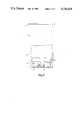
- FIG. 3is a perspective view of the receptacle of FIG. 2.
- the consistometer shown in FIG. 1comprises a framework 1 which supports a casing 2 of generally cylindrical shape, made of a non-magnetic material, such, for example, as aluminium or an aluminium alloy, internally defining a consistometer enclosure 3, and housing a motor with a speed reducer 4 driving a drive shaft 6 via a torquemeter 5.
- a casing 2of generally cylindrical shape, made of a non-magnetic material, such, for example, as aluminium or an aluminium alloy, internally defining a consistometer enclosure 3, and housing a motor with a speed reducer 4 driving a drive shaft 6 via a torquemeter 5.
- the enclosure 3is closed at its upper part by an upper plug 7 which can be screwed into the casing 2 by means of demountable handles 8.
- the upper plug 7carries an elongate receptacle 9 for a rheologically changing material, which is made of aluminium alloy, and which can be seen better in FIGS. 2 and 3.
- the receptacle 9has the shape of a body of revolution, e.g. a cylinder, for example of 60 mm bore, whose side wall is provided with openings or windows 10, whose open upper end carriers a collar or flange 11 and whose lower end is closed by a lower plug 12.
- Plug 12may be screwed into the side wall of the receptacle 9, into a reinforced section of this wall.
- the plug 12carries a rotary shaft seal 13, for example a Paulstra type IE seal. Satisfactory centering of the plug 12 and, consequently, of the shaft seal 13 is produced by a bearing 14 provided at the end of the plug threading, which engages in a corresponding cavity in the wall of the receptacle 9.
- the receptacle 9is fastened to the upper plug 7 by clamping the collar 11 against the plug by means of a fast-screw ring 16, as can be seen in FIG. 1.
- the receptacle 9contains a stirrer 17 carried by a driving spindle 18 which passes through the shaft seal 13 and extends downwards out of the receptacle 9 and which bears with its upper end on a pivot 19 arranged in the upper plug 7.
- the casing 2is extended downwards by a central extension 20. Outside this extension 20 and around it there is arranged a driving permanent magnet 21, linked in rotation with the driving shaft 6.
- a driven permanent magnet 22which is integrally fixed in rotation to an intermediate transmission shaft 23 bearing a coupling device 24 is arranged inside the extension 20 and facing the driving magnet 21.
- the extension 20is used to support bearings for these two magnets 21 and 22.
- the coupling device 24comprises a housing 25 intended to receive the lower end of the spindle 18.
- the lower end of the spindleis laterally provided with a vertical groove 26 into which a lateral stud 27 can extend. Stud 27 is carried by the coupling device 24 and biassed by a spring inwardly of the housing 25.
- the coupling device 24biassed by a spring inwardly of the housing 25.
- the proceduremay be as follows.
- the stirrer 17is placed in the receptacle 9 and the assembly is fastened to the upper plug 7 by screwing up the ring 16 using a special key.
- the membrane 15is pulled on to the receptacle 9, care being taken to leave a similar length on each side of the windows 10, and the receptacle 9 is inverted and filled, for example with cement slag.
- the lower plug 12is slipped on to the spindle 18 by placing the point of the spindle 18 in the pivot 19, and then the lower plug 12 is screwed on the the receptacle 9 using a special key.
- the assembly of the upper plug 7 and of the closed receptacle 9, to which it is fastened,is then inverted and introduced into the consistometer enclosure 3.
- the receptacle 9 and the spindle 18, whose lower end automatically engages in the coupling device 24,are placed in working position.
- the stirrer 17is driven at a constant speed, for example at 150 revolutions/minute.
- the temperature and the pressurecan be varied according to a programme; in the case of a cement slag for well drilling, this programme is specified in accordance with the API standards.
- the change in the driving torque measured by the torquemeter 5is recorded as a function of time in order to determine the setting time of the slag.
- the torquemeter 5it would also be possible to measure the current of the motor 4, but the measurement of the consistency of the slag performed in this manner would be less accurate.
- a consistometerhaving a simplified construction, the use of which can be universal, but which retains good accuracy of measurement.
- the consistometeralso permits a reduction of the time and, consequently, the cost of the handling operations preceding and following the measurement period as such.
- the rotary stirreris automatically placed in a working position as soon as it is installed in the consistometer enclosure and is coupled without mechanical contact to means for driving the stirrer in rotation and for measuring the drive torque which are located outside the enclosure.
Landscapes
- Immunology (AREA)
- Physics & Mathematics (AREA)
- Life Sciences & Earth Sciences (AREA)
- Chemical & Material Sciences (AREA)
- Analytical Chemistry (AREA)
- Biochemistry (AREA)
- General Health & Medical Sciences (AREA)
- General Physics & Mathematics (AREA)
- Health & Medical Sciences (AREA)
- Pathology (AREA)
- Sampling And Sample Adjustment (AREA)
- Investigating Strength Of Materials By Application Of Mechanical Stress (AREA)
- Investigating Or Analyzing Materials Using Thermal Means (AREA)
- Mixers Of The Rotary Stirring Type (AREA)
- Curing Cements, Concrete, And Artificial Stone (AREA)
- Measuring Or Testing Involving Enzymes Or Micro-Organisms (AREA)
- Pressure Vessels And Lids Thereof (AREA)
- Analysing Materials By The Use Of Radiation (AREA)
Abstract
Description
Claims (8)
Applications Claiming Priority (2)
| Application Number | Priority Date | Filing Date | Title |
|---|---|---|---|
| FR8602701AFR2594950B1 (en) | 1986-02-27 | 1986-02-27 | CONSISTOMETER FOR ANALYSIS OF RHEOLOGICAL DEVELOPMENT, ESPECIALLY FOR USE ON A SITE |
| FR8602701 | 1986-02-27 |
Publications (1)
| Publication Number | Publication Date |
|---|---|
| US4736624Atrue US4736624A (en) | 1988-04-12 |
Family
ID=9332575
Family Applications (1)
| Application Number | Title | Priority Date | Filing Date |
|---|---|---|---|
| US07/013,498Expired - Fee RelatedUS4736624A (en) | 1986-02-27 | 1987-02-11 | Consistometer for analysis of rheological change |
Country Status (14)
| Country | Link |
|---|---|
| US (1) | US4736624A (en) |
| EP (1) | EP0236205B1 (en) |
| JP (1) | JP2518638B2 (en) |
| AU (1) | AU587310B2 (en) |
| BR (1) | BR8700899A (en) |
| CA (1) | CA1274988A (en) |
| DE (1) | DE3767509D1 (en) |
| DK (1) | DK166844B1 (en) |
| FI (1) | FI90468C (en) |
| FR (1) | FR2594950B1 (en) |
| GB (1) | GB2187295B (en) |
| IE (1) | IE59838B1 (en) |
| MX (1) | MX169137B (en) |
| NO (1) | NO169362C (en) |
Cited By (11)
| Publication number | Priority date | Publication date | Assignee | Title |
|---|---|---|---|---|
| EP0397235A3 (en)* | 1989-05-05 | 1992-10-21 | Helmut Gerard | Apparatus for determining the solidification point of a plaster-water mixture |
| GB2304197A (en)* | 1995-08-11 | 1997-03-12 | Inst Francais Du Petrole | Testing cell designed to detect phase changes in a fluid mixture |
| US5652376A (en)* | 1996-07-05 | 1997-07-29 | Dow Corning Corporation | Method of measuring yield stress |
| US6257051B1 (en) | 1999-03-11 | 2001-07-10 | The Lubrizol Corporation | On-board rotational viscometers |
| US6412338B2 (en) | 1999-03-11 | 2002-07-02 | The Lubrizol Corporation | On-board rotational viscometers |
| US7287416B1 (en) | 2005-10-24 | 2007-10-30 | Hongfeng Bi | Low maintenance high pressure viscometer |
| US7412877B1 (en) | 2005-10-24 | 2008-08-19 | Hongfeng Bi | High pressure viscometer with chamber preventing sample contamination |
| US20120024046A1 (en)* | 2010-07-30 | 2012-02-02 | Yuwei Luo | Measuring device for measuring consistency of cement slurry for a consistometer |
| US20120048008A1 (en)* | 2010-08-26 | 2012-03-01 | Halliburton Energy Services, Inc. | Apparatus and methods for continuous compatibility testing of subterranean fluids and their compositions under wellbore conditions |
| US8375771B1 (en) | 2010-05-21 | 2013-02-19 | Hongfeng Bi | Viscometer for testing cement rheology |
| US11067490B2 (en)* | 2016-04-29 | 2021-07-20 | Neotek Bioscience Co., Ltd. | Bracket, support system, and thrombelastography device and use method thereof |
Families Citing this family (4)
| Publication number | Priority date | Publication date | Assignee | Title |
|---|---|---|---|---|
| DE8902190U1 (en)* | 1989-02-24 | 1989-06-29 | Contraves GmbH, 7768 Stockach | Device for determining or measuring a substance |
| FR2678381B1 (en)* | 1991-06-27 | 1994-10-07 | Total Sa | CONSISTOMETER. |
| FR2687223B1 (en)* | 1992-02-12 | 1995-04-07 | Inst Francais Du Petrole | DEVICE AND METHOD FOR MONITORING VARIATIONS IN THE CONSISTENCY OF A MIXTURE. |
| SE503681C2 (en)* | 1994-11-21 | 1996-07-29 | Reologica Instr Ab | Rheological measuring device |
Citations (4)
| Publication number | Priority date | Publication date | Assignee | Title |
|---|---|---|---|---|
| US4466276A (en)* | 1982-09-28 | 1984-08-21 | Autoclave Engineers, Inc. | Consistometer |
| US4524611A (en)* | 1982-05-11 | 1985-06-25 | Association Pour La Recherche Et Le Developpement Des Methodes Et Processus Industriels (Armines) | Rheometer for measuring high pressure and high temperature with sampling |
| US4534209A (en)* | 1983-09-15 | 1985-08-13 | Sanders Howard E | Atmospheric consistometer |
| US4633708A (en)* | 1984-08-31 | 1987-01-06 | Total Compagnie Francaise Des Petroles | Consistometer container for testing rheologically evolutive material |
Family Cites Families (3)
| Publication number | Priority date | Publication date | Assignee | Title |
|---|---|---|---|---|
| US3435666A (en)* | 1966-07-18 | 1969-04-01 | Champion Lab Inc | Viscometer |
| US4175425A (en)* | 1977-04-08 | 1979-11-27 | Brookfield David A | Viscometer |
| GB2097940A (en)* | 1981-05-05 | 1982-11-10 | Viscometers Uk Ltd | Rotary viscometer |
- 1986
- 1986-02-27FRFR8602701Apatent/FR2594950B1/ennot_activeExpired
- 1987
- 1987-02-02GBGB8702220Apatent/GB2187295B/ennot_activeExpired
- 1987-02-11USUS07/013,498patent/US4736624A/ennot_activeExpired - Fee Related
- 1987-02-12CACA000529594Apatent/CA1274988A/ennot_activeExpired - Lifetime
- 1987-02-17EPEP87400338Apatent/EP0236205B1/ennot_activeExpired - Lifetime
- 1987-02-17DEDE8787400338Tpatent/DE3767509D1/ennot_activeExpired - Lifetime
- 1987-02-19MXMX005284Apatent/MX169137B/enunknown
- 1987-02-24AUAU69188/87Apatent/AU587310B2/ennot_activeCeased
- 1987-02-25IEIE48387Apatent/IE59838B1/ennot_activeIP Right Cessation
- 1987-02-25BRBR8700899Apatent/BR8700899A/ennot_activeIP Right Cessation
- 1987-02-26NONO870799Apatent/NO169362C/enunknown
- 1987-02-26FIFI870836Apatent/FI90468C/ennot_activeIP Right Cessation
- 1987-02-26DKDK099087Apatent/DK166844B1/ennot_activeIP Right Cessation
- 1987-02-27JPJP62045063Apatent/JP2518638B2/ennot_activeExpired - Lifetime
Patent Citations (4)
| Publication number | Priority date | Publication date | Assignee | Title |
|---|---|---|---|---|
| US4524611A (en)* | 1982-05-11 | 1985-06-25 | Association Pour La Recherche Et Le Developpement Des Methodes Et Processus Industriels (Armines) | Rheometer for measuring high pressure and high temperature with sampling |
| US4466276A (en)* | 1982-09-28 | 1984-08-21 | Autoclave Engineers, Inc. | Consistometer |
| US4534209A (en)* | 1983-09-15 | 1985-08-13 | Sanders Howard E | Atmospheric consistometer |
| US4633708A (en)* | 1984-08-31 | 1987-01-06 | Total Compagnie Francaise Des Petroles | Consistometer container for testing rheologically evolutive material |
Cited By (15)
| Publication number | Priority date | Publication date | Assignee | Title |
|---|---|---|---|---|
| EP0397235A3 (en)* | 1989-05-05 | 1992-10-21 | Helmut Gerard | Apparatus for determining the solidification point of a plaster-water mixture |
| GB2304197A (en)* | 1995-08-11 | 1997-03-12 | Inst Francais Du Petrole | Testing cell designed to detect phase changes in a fluid mixture |
| GB2304197B (en)* | 1995-08-11 | 1999-07-28 | Inst Francais Du Petrole | Testing cell for fluid mixtures designed to detect phase changes |
| US5652376A (en)* | 1996-07-05 | 1997-07-29 | Dow Corning Corporation | Method of measuring yield stress |
| AU711991B2 (en)* | 1996-07-05 | 1999-10-28 | Dow Corning Corporation | Method of monitoring and controlling yield stress |
| US6412338B2 (en) | 1999-03-11 | 2002-07-02 | The Lubrizol Corporation | On-board rotational viscometers |
| US6257051B1 (en) | 1999-03-11 | 2001-07-10 | The Lubrizol Corporation | On-board rotational viscometers |
| US7287416B1 (en) | 2005-10-24 | 2007-10-30 | Hongfeng Bi | Low maintenance high pressure viscometer |
| US7412877B1 (en) | 2005-10-24 | 2008-08-19 | Hongfeng Bi | High pressure viscometer with chamber preventing sample contamination |
| US8375771B1 (en) | 2010-05-21 | 2013-02-19 | Hongfeng Bi | Viscometer for testing cement rheology |
| US20120024046A1 (en)* | 2010-07-30 | 2012-02-02 | Yuwei Luo | Measuring device for measuring consistency of cement slurry for a consistometer |
| US8820145B2 (en)* | 2010-07-30 | 2014-09-02 | China Oilfield Services Limited | Measuring device for measuring consistency of cement slurry for a consistometer |
| US20120048008A1 (en)* | 2010-08-26 | 2012-03-01 | Halliburton Energy Services, Inc. | Apparatus and methods for continuous compatibility testing of subterranean fluids and their compositions under wellbore conditions |
| US8347693B2 (en)* | 2010-08-26 | 2013-01-08 | Halliburton Energy Services, Inc. | Apparatus and methods for continuous compatibility testing of subterranean fluids and their compositions under wellbore conditions |
| US11067490B2 (en)* | 2016-04-29 | 2021-07-20 | Neotek Bioscience Co., Ltd. | Bracket, support system, and thrombelastography device and use method thereof |
Also Published As
| Publication number | Publication date |
|---|---|
| FI870836L (en) | 1987-08-28 |
| EP0236205A1 (en) | 1987-09-09 |
| IE59838B1 (en) | 1994-04-06 |
| EP0236205B1 (en) | 1991-01-23 |
| GB8702220D0 (en) | 1987-03-11 |
| BR8700899A (en) | 1987-12-15 |
| AU6918887A (en) | 1987-09-03 |
| DK99087D0 (en) | 1987-02-26 |
| JP2518638B2 (en) | 1996-07-24 |
| DK99087A (en) | 1987-08-28 |
| DK166844B1 (en) | 1993-07-19 |
| AU587310B2 (en) | 1989-08-10 |
| FI870836A0 (en) | 1987-02-26 |
| FR2594950B1 (en) | 1988-05-06 |
| NO169362B (en) | 1992-03-02 |
| CA1274988A (en) | 1990-10-09 |
| MX169137B (en) | 1993-06-23 |
| FI90468B (en) | 1993-10-29 |
| NO870799D0 (en) | 1987-02-26 |
| DE3767509D1 (en) | 1991-02-28 |
| IE870483L (en) | 1987-08-27 |
| GB2187295A (en) | 1987-09-03 |
| GB2187295B (en) | 1989-11-29 |
| NO169362C (en) | 1992-06-10 |
| FR2594950A1 (en) | 1987-08-28 |
| JPS62204142A (en) | 1987-09-08 |
| NO870799L (en) | 1987-08-28 |
| FI90468C (en) | 1994-02-10 |
Similar Documents
| Publication | Publication Date | Title |
|---|---|---|
| US4736624A (en) | Consistometer for analysis of rheological change | |
| US4524611A (en) | Rheometer for measuring high pressure and high temperature with sampling | |
| JPH10506999A (en) | Container moving device and method for moving container | |
| GB1523380A (en) | Machine for testing specimens of materials for friction and wear | |
| EP0398002A3 (en) | Device for the automatic ultrasonic inspection of tube ends | |
| EP0574393B1 (en) | A device for rapidly performing a sedimentation-rate test | |
| CN108426866B (en) | Heavy metal detection device and detection method | |
| CN118329529B (en) | Sampling device for water quality detection for aquaculture | |
| CN109764799A (en) | A kind of waterproof displacement measuring device | |
| CN219245169U (en) | Multitube formula river water environment monitoring sampler | |
| CN210180725U (en) | Depthkeeping water sample collection system | |
| SE8400288L (en) | DEVICE FOR TAKING AND SETTING BLOOD SINK | |
| CN116500127A (en) | Ultrasonic static gel strength analyzer | |
| US5517850A (en) | Rotor-stator adapters with internally threaded stator collar externally threaded nut for sensitive rotating viscometers | |
| CN109443844B (en) | Ore pulp sampling and iron grade signal acquisition device and method | |
| CN87207349U (en) | Rheometer for determining two-parameter with rotary inner vane in outer drum | |
| IE43354L (en) | Automatic sampling apparatus | |
| CN112782417A (en) | Multifunctional test tube rotating device, test tube code scanning device and test tube code scanning method | |
| CN221725602U (en) | A sampling device for agricultural testing equipment | |
| CN218674366U (en) | Bagged cement sampler | |
| SU1249391A1 (en) | Device for field determining of mechanical properties of ground | |
| CN222353725U (en) | A sample container for a bonding index tester | |
| CN221326078U (en) | Sample solid-liquid separation device for food detection | |
| CN220411315U (en) | Diagnostic kit for multiple uses | |
| CN215678428U (en) | Calibration and calibration device for instrument sensor |
Legal Events
| Date | Code | Title | Description |
|---|---|---|---|
| AS | Assignment | Owner name:TOTAL COMPAGNIE FRANCAISE DES PETROLES, 5, RUE MIC Free format text:ASSIGNMENT OF ASSIGNORS INTEREST.;ASSIGNORS:ARNSTEIN, RODOLPHE;BISSON, PATRICK;BLAQUIERE, MARC P.;REEL/FRAME:004822/0710 Effective date:19870202 Owner name:TOTAL COMPAGNIE FRANCAISE DES PETROLES,FRANCE Free format text:ASSIGNMENT OF ASSIGNORS INTEREST;ASSIGNORS:ARNSTEIN, RODOLPHE;BISSON, PATRICK;BLAQUIERE, MARC P.;REEL/FRAME:004822/0710 Effective date:19870202 | |
| FEPP | Fee payment procedure | Free format text:PAYOR NUMBER ASSIGNED (ORIGINAL EVENT CODE: ASPN); ENTITY STATUS OF PATENT OWNER: LARGE ENTITY | |
| FPAY | Fee payment | Year of fee payment:4 | |
| FEPP | Fee payment procedure | Free format text:PAYER NUMBER DE-ASSIGNED (ORIGINAL EVENT CODE: RMPN); ENTITY STATUS OF PATENT OWNER: LARGE ENTITY Free format text:PAYOR NUMBER ASSIGNED (ORIGINAL EVENT CODE: ASPN); ENTITY STATUS OF PATENT OWNER: LARGE ENTITY | |
| FPAY | Fee payment | Year of fee payment:8 | |
| REMI | Maintenance fee reminder mailed | ||
| LAPS | Lapse for failure to pay maintenance fees | ||
| FP | Lapsed due to failure to pay maintenance fee | Effective date:20000412 | |
| STCH | Information on status: patent discontinuation | Free format text:PATENT EXPIRED DUE TO NONPAYMENT OF MAINTENANCE FEES UNDER 37 CFR 1.362 |