US4735203A - Retractable lancet - Google Patents
Retractable lancetDownload PDFInfo
- Publication number
- US4735203A US4735203AUS06/941,164US94116486AUS4735203AUS 4735203 AUS4735203 AUS 4735203AUS 94116486 AUS94116486 AUS 94116486AUS 4735203 AUS4735203 AUS 4735203A
- Authority
- US
- United States
- Prior art keywords
- housing
- carrier
- spring
- carrier means
- blade
- Prior art date
- Legal status (The legal status is an assumption and is not a legal conclusion. Google has not performed a legal analysis and makes no representation as to the accuracy of the status listed.)
- Expired - Lifetime
Links
Images


Classifications
- A—HUMAN NECESSITIES
- A61—MEDICAL OR VETERINARY SCIENCE; HYGIENE
- A61B—DIAGNOSIS; SURGERY; IDENTIFICATION
- A61B5/00—Measuring for diagnostic purposes; Identification of persons
- A61B5/15—Devices for taking samples of blood
- A61B5/151—Devices specially adapted for taking samples of capillary blood, e.g. by lancets, needles or blades
- A61B5/15142—Devices intended for single use, i.e. disposable
- A—HUMAN NECESSITIES
- A61—MEDICAL OR VETERINARY SCIENCE; HYGIENE
- A61B—DIAGNOSIS; SURGERY; IDENTIFICATION
- A61B5/00—Measuring for diagnostic purposes; Identification of persons
- A61B5/15—Devices for taking samples of blood
- A61B5/150007—Details
- A61B5/150015—Source of blood
- A61B5/150022—Source of blood for capillary blood or interstitial fluid
- A—HUMAN NECESSITIES
- A61—MEDICAL OR VETERINARY SCIENCE; HYGIENE
- A61B—DIAGNOSIS; SURGERY; IDENTIFICATION
- A61B5/00—Measuring for diagnostic purposes; Identification of persons
- A61B5/15—Devices for taking samples of blood
- A61B5/150007—Details
- A61B5/150374—Details of piercing elements or protective means for preventing accidental injuries by such piercing elements
- A61B5/150381—Design of piercing elements
- A61B5/150442—Blade-like piercing elements, e.g. blades, cutters, knives, for cutting the skin
- A61B5/150465—Specific design of proximal end
- A—HUMAN NECESSITIES
- A61—MEDICAL OR VETERINARY SCIENCE; HYGIENE
- A61B—DIAGNOSIS; SURGERY; IDENTIFICATION
- A61B5/00—Measuring for diagnostic purposes; Identification of persons
- A61B5/15—Devices for taking samples of blood
- A61B5/151—Devices specially adapted for taking samples of capillary blood, e.g. by lancets, needles or blades
- A61B5/15101—Details
- A61B5/15103—Piercing procedure
- A61B5/15107—Piercing being assisted by a triggering mechanism
- A61B5/15113—Manually triggered, i.e. the triggering requires a deliberate action by the user such as pressing a drive button
- A—HUMAN NECESSITIES
- A61—MEDICAL OR VETERINARY SCIENCE; HYGIENE
- A61B—DIAGNOSIS; SURGERY; IDENTIFICATION
- A61B5/00—Measuring for diagnostic purposes; Identification of persons
- A61B5/15—Devices for taking samples of blood
- A61B5/151—Devices specially adapted for taking samples of capillary blood, e.g. by lancets, needles or blades
- A61B5/15101—Details
- A61B5/15115—Driving means for propelling the piercing element to pierce the skin, e.g. comprising mechanisms based on shape memory alloys, magnetism, solenoids, piezoelectric effect, biased elements, resilient elements, vacuum or compressed fluids
- A61B5/15117—Driving means for propelling the piercing element to pierce the skin, e.g. comprising mechanisms based on shape memory alloys, magnetism, solenoids, piezoelectric effect, biased elements, resilient elements, vacuum or compressed fluids comprising biased elements, resilient elements or a spring, e.g. a helical spring, leaf spring, or elastic strap
- A—HUMAN NECESSITIES
- A61—MEDICAL OR VETERINARY SCIENCE; HYGIENE
- A61B—DIAGNOSIS; SURGERY; IDENTIFICATION
- A61B5/00—Measuring for diagnostic purposes; Identification of persons
- A61B5/15—Devices for taking samples of blood
- A61B5/151—Devices specially adapted for taking samples of capillary blood, e.g. by lancets, needles or blades
- A61B5/15101—Details
- A61B5/15126—Means for controlling the lancing movement, e.g. 2D- or 3D-shaped elements, tooth-shaped elements or sliding guides
- A61B5/1513—Means for controlling the lancing movement, e.g. 2D- or 3D-shaped elements, tooth-shaped elements or sliding guides comprising linear sliding guides
- A—HUMAN NECESSITIES
- A61—MEDICAL OR VETERINARY SCIENCE; HYGIENE
- A61B—DIAGNOSIS; SURGERY; IDENTIFICATION
- A61B5/00—Measuring for diagnostic purposes; Identification of persons
- A61B5/15—Devices for taking samples of blood
- A61B5/151—Devices specially adapted for taking samples of capillary blood, e.g. by lancets, needles or blades
- A61B5/15142—Devices intended for single use, i.e. disposable
- A61B5/15144—Devices intended for single use, i.e. disposable comprising driving means, e.g. a spring, for retracting the piercing unit into the housing
Definitions
- the inventionconcerns a lancet assembly, and more particularly concerns an automatically retractable non-reusable lancet assembly.
- Sharp pointed or blade-like lancetsare employed to make a quick puncture or penetration of the skin of a patient to cause a small flow of blood.
- Various testsrequire a relatively small amount of blood, for example a drop smeared upon a slide or the like for microscopic viewing, such that the amount of blood flowing from a finger prick of this type is normally sufficient.
- various bleeding time testsare often employed in which the time running from the puncture of the skin until the cessation of blood flow is measured. Such bleeding time provides a measure from which, by reference to tables or the like, the clotting factors and/or other such relevant information concerning a patient's blood chemistry can be estimated.
- the nerve endings in the finger tip areaare quite sensitive, even such minimal skin punctures may be quite irritating and/or painful.
- the lancetbe designed so that the speed, effective time of penetration, and depth of penetration are standardized and repeatable from one lancet device to the next.
- the retractable feature of some of these lancetsis also desirable, in that it prevents reuse of the lancet, and requires disposal of the same after but one use. This is important for at least two reasons: firstly, for health and sanitary reasons it is inadvisable to reuse the same lancet on a second patient; and secondly, some technicians might reuse the blade of a preloaded or spring-loaded lancet after an initial firing thereof without restressing or preloading the spring, but rather by merely manually making the puncture, thus failing to take advantage of the preloaded, controlled force and velocity of the action thereof.
- some of the prior art devicesleave the cutting edge or point extended from the body or housing of the lancet after firing and may or may not permit reloading or recompression of the springs or other members which accomplish firing.
- Some other lancetsutilize a multiple spring arrangement, such as those shown in some of the Burns or Burns et al patents noted above.
- such assembliesare relatively complex and require a number of interfitting parts which are relatively difficult to manufacture and accurately assemble.
- the use of two springs, one for firing of the lancet point or blade and a second for retracting the same after firingpresents a number of problems in accurately reproducing the tensile strengths and behavior, both in compression and upon release, of two oppositely acting springs. These factors can be difficult to uniformly reproduce in practice, at least in a relatively inexpensive, disposable product. This difficulty is due not only to the problems in selecting and properly mounting and pretensioning the springs themselves, but also in the difficulty of maintaining uniformity of housing or other casing parts within which the springs are mounted, maintaining accurate dimensions, controlling frictional forces, and the like.
- Our apparatuscomprises a housing having an end opening, a blade, and a carrier for fixedly mounting the blade and mounted in the housing for sliding motion toward and away from the end opening.
- a resilient biasing memberis mounted in the housing in a prestressed condition and is operatively coupled for selectively urging the carrier for achieving sliding motion toward and away from the housing end opening.
- a non-resettable release membernormally retains the biasing member in its prestressed condition and is selectively activatable for releasing the resilient biasing member to urge the carrier in a sliding motion for projecting at least a cutting edge of the blade through the end opening.
- Cooperating surfaces on the housing and carrierdefine respective limits of sliding motion of the carrier corresponding to extended and retracted positions of the blade cutting edge relative to the housing end opening.
- the resilient biasing memberis operatively engaged with the carrier for achieving a compound sliding movement of the carrier comprising an initial portion including extension of the carrier for projecting the blade cutting edge outwardly of the housing end opening, immediately followed by a second portion including retraction of the carrier for retraction of the blade cutting edge back into the housing.
- FIG. 1is a perspective view of a retractable lancet in accordance with the invention
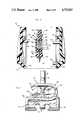
- FIG. 2is an enlarged, developmental view, taken generally along the line 2--2 indicated in FIG. 1, and illustrating details of the internal construction thereof;
- FIG. 3is a developmental view taken generally along the line 3--3 of FIG. 2;
- FIG. 4is a view similar to FIG. 2 and illustrating an initial portion of a compound movement of the lancet device of the invention upon firing thereof;
- FIG. 5is a view similar to FIGS. 2 and 4 and illustrating a second portion or retraction portion of the compound movement of the lancet device of the invention upon firing thereof;
- FIG. 6is an exploded view similar to FIG. 3, and illustrating the assembly of the components of the lancet of the invention.
- FIG. 7is a side elevation of a preassembled spring and blade carrier portion of the lancet apparatus of the invention, somewhat enlarged from the previous views;
- FIG. 8is a view similar to FIG. 2, of a retractable lancet in accordance with a second embodiment of the invention, in its assembled condition and prior to use thereof;
- FIG. 9is a view of the embodiment of FIG. 8, and in similar fashion to FIG. 4, illustrating a first portion of the compound motion of the blade thereof;
- FIG. 10is a view of the embodiment of FIGS. 8 and 9, and in similar fashion to FIG. 5, illustrating the second or retraction portion of the compound motion thereof;
- FIG. 11is a partial sectional view taken generally in the plane of the line 11--11 of FIG. 8, and
- FIG. 12is an enlarged end view of a cam member of the embodiment of FIGS. 8-11.
- a retractable, nonreusable bleeding time lancet in accordance with the inventionis designated generally by the reference numeral 20.
- the lancet 20includes a housing 22 which, in the preferred form illustrated, is comprised of two similar and complementary shell portions 24, 26 each of which define substantially one-half of the housing, and more particularly define respective front and rear halves thereof. Aside from housing 22, little else is visible in FIG. 1, which it should be noted is shown greatly enlarged over the actual size of the apparatus.
- the assembled lancetgenerally appears substantially as seen in FIG. 1. That is, the puncturing or blade member thereof is only fired or ejected therefrom for a relatively short time, on the order of a fraction of one second, and is immediately retracted, such that it is difficult even to visually observe the brief extension of the blade in practice.
- FIGS. 2 and 3these further enlarged views of lancet 20 further reveal a blade or blade means 28 and carrier means 30 which fixedly mounts the blade 28.
- the carrier 30is mounted in the housing 22 for slidable movement generally toward and away from an end opening 32 of the housing, through which the blade 28 briefly projects when the device is operated, to puncture the skin of a patient.
- Resilient biasing meanswhich, in the illustrated embodiment, comprises a single coil-type spring 34, is mounted in the housing 22 in a prestressed condition as will be more fully explained hereinbelow.
- This resilient biasing means or spring 34is further operatively coupled with the carrier 30 for resiliently selectably urging the same in a sliding motion toward and away from the housing end opening.
- a non-resettable release means in the illustrated embodimentcomprises a projecting post or trigger member or portion 37 on the carrier 30 and a cooperating clip member 38. These members are operatively coupled for normally retaining the biasing means or spring 34 in its prestressed condition.
- a frangible tab 41is molded into one or both housing halves 24, 26 in a position so as to generally overlie the outwardly projecting end of clip 38. Absence of this breakaway tab will indicate that the device has been used and is to be discarded. This acts as a further back-up feature to the nonresettable nature of the device as described herein
- depression of a projecting outer end 40 of the clip member 38will break tab 41 and release the projecting post or trigger member 37 from its retained condition to permit this prestressed spring 34 to generally uncoil or move toward a relaxed position thereof.
- the spring 34urges the carrier 30 initially toward the opening 32 and an extended position thereof wherein the blade 28 or at least an endmost cutting edge 36 thereof extends or projects through the opening 32 for puncturing the skin of the patient.
- the housing 22 and carrier 30further have cooperating means formed thereon in the form of respective abutting or stop surfaces 42, 44 and 46, 48 for defining respective limits of sliding motion of the carrier relative to the housing. These limits of motion correspond to the retracted position of the blade shown in FIGS. 2 and 3 and the extended or projecting position shown in FIG. 4, to which reference is also invited.
- the coil springcomprises a helical body portion 50 and at least one outwardly projecting free end portion or arm 52.
- a second, opposite outwardly projecting free end or arm 54is also provided.
- This second abutment surface 56comprises a projecting rim or rib portion of an interior of the housing 22 which defines a surface which is generally parallel and spaced from, and mutually inwardly facing, with respect to surface 42.
- the surface 56is relatively closer to end opening 32 than the first abutment surface 42.
- the means for operatively engaging the springfurther include a compartment 60 formed within the carrier 30 for receiving or mounting the body portion 50 of the spring.
- This compartmenthas a floor or lower surface portion 62 which also abuts the opposite free end or arm 54 of the spring.
- FIGS. 2, 4 and 5initially, as shown in FIG. 2, the free end or arm 52 of the spring abuts housing surface 42. Upon release of the clip 40, this arm 52 continues to abut and push against fixed wall or surface 42 so as to thereby drive the remainder of spring and the carrier 30 in which the body 54 is mounted generally downwardly or toward the end opening 32.
- the effective projection or length of arm 52is selected to result in extension of the cutting portion 36 of the blade 28 outwardly of the opening 32 in the housing when the arm reaches a generally fully extended or substantially vertically oriented position relative to the housing and surface 42, as illustrated in FIG. 4.
- a last or outermost coil 63 of the springextends outwardly of the floor or lower surface portion 62 of the compartment 60. This allows for some manufacturing variations or tolerances in the length of the arm 52 and in the thicknesses and relative locations of the respective stop surfaces 42 and 56. That is, this compliance or play allowed by the projection of the coil 63 outwardly of the housing floor 62 permits this last coil to deform downwardly somewhat as the arm 52 rotates in engagement with surface 42 and prevents the arm from "hanging up" on surface 42.
- the trigger post and clip 38cooperate by means of a pair of notches or slots 70 formed in the trigger post and a cooperating elongate slot 72 formed in the clip 38 which defines shoulders for engaging the slots 70.
- the spring 52although in a relaxed or nearly relaxed state, reliably holds the blade in the retracted position shown in FIG. 5.
- the coil spring 34is selected and/or formed so as to provide a predetermined controlled amount of force and acceleration to the blade for maintaining a controlled amount of force and time of contact of the blade cutting edge with the skin of the patient.
- the amount of extension of the blade relative to the housing shown in FIG. 4is selected to achieve the desired depth of penetration of skin to carry out the bleeding time tests in accordance with the standard so-called Ivy technique.
- the carrier means 30will be seen to be configured for receiving the blade 28 in a generally snap-on fit arrangement, being provided with a blade-receiving fitting arrangement 80, generally complementary in form for receiving blade 28 which, as best viewed in FIGS. 2, 4 and 5, has a through aperture 82, for this purpose.
- a blade-receiving fitting arrangement 80generally complementary in form for receiving blade 28 which, as best viewed in FIGS. 2, 4 and 5, has a through aperture 82, for this purpose.
- an overhang portion of the fitting 80designated generally at reference numeral 84, overlies and engages a top surface of the blade 28 to hold the same firmly in engagement with the carrier 30.
- the spring-receiving compartment 60includes a generally downwardly depending lip portion or retaining portion 86 which will be seen to have a downwardly flared, ramped or cam surface 88.
- the free end 52 of the springis prestressed in the manner shown in FIGS. 6 and 7 and placed entirely within the compartment 60 and behind the retaining lip 86. This greatly facilitates assembly of the now preassembled carrier, blade and spring with the two halves or shells 24, 26 of the housing 22.
- the clip 38is also preassembled with the trigger post 37 of the carrier prior to assembly thereof with the housing halves or shells 24, 26.
- one of the housing halves or shells, and in the illustrated embodiment the shell or half 24,is provided with a loading means in the form of a projecting pin or post 90 which is configured and located for engaging and urging the spring free end 52 back outwardly of the lip 86 upon assembly of the housing with the carrier.
- the ramp-like or cam-like nature of the surface 88 of the lip 86facilitates the disengagement of spring end 52 in this regard. Upon this initial movement of the spring end 52, the same is free to engage the abutment surface 42 as previously described with reference to FIGS. 2-4.
- the trigger post 36extends through an aperture 92 provided therefor through the abutment surface or upper wall 42.
- substantially one-half of the abutment surface 42 and throug aperture 92is formed in each of the housing halves or shell members 24, 26.
- the clip member 38also extends over and generally rests upon the upper surface of abutment surface or wall 42, with the actuating end 40 thereof, upon initial assembly, extending outwardly of a through aperture 94, provided therefor in the sidewall of the housing 22 (see FIG. 2).
- a retractable bleeding time lancet in accordance with a second embodiment of the inventionis designated generally by the reference numeral 120.
- the structure of the device of FIGS. 8-11is similar to that previously described with reference to the embodiment shown in FIGS. 1-7.
- the device 120includes a housing 122 preferably formed of similar housing shells or halves 124, 126.
- a blade 128is mounted to a carrier means or member 130 which is in turn mounted for bi-directional sliding movement within the housing.
- the bladehas a cutting edge 136, which in use is projected and retracted relative to a housing end opening 132.
- a retention and release means or mechanism for the carrier 130may be generally of the same form described hereinabove with reference to elements 37, 38 of FIGS. 1-7, and is not illustrated in FIGS. 8-12. That is, the carrier 130 may be provided with an upwardly projecting release pin or member 137 which cooperates with a suitable clip or other means (not shown) in an upper portion of the housing in much the same fashion as illustrated and described above with reference to FIGS. 1-7.
- the device 120includes a resilient biasing means in the form of a similar coiled spring 34, which has a generally helical body portion 50, here mounted over a receiving pin or post 151, and generally oppositely outwardly projecting free ends or arms 152 and 154.
- the arm 152is engaged or in abutment with an abutment surface comprising a pin 142, which functions similarly to the surface 42 in the embodiment of FIGS. 1-7.
- the carrier 130mounts the blade 128 by means of complementary receiving surfaces 180, 184 similar to those (80, 84) illustrated and described above with reference to the embodiment of FIGS. 1-7. Moreover, respective abutment surfaces or stop surfaces 146 of the housing 120, and 148 of the carrier 130, define the fully extended position of the carrier relative to the housing, for projecting the blade 128 outwardly thereof during use.
- the cam member 200will be seen to comprise a generally flat body portion 202 which is rotatably mounted to the housing 120 by a projecting shaft member or portion 204.
- shaft 204is formed on the cam 200; however, other arrangements for achieving this rotational mounting may be utilized without departing from the invention.
- the cam 200further includes a first or driven projection or pin-like member or portion 206 which is engaged by the free end 154 of spring 134.
- a second, driving projection or pin-like member or portion 208engages a first abutment surface 210 of the carrier.
- Projection 208drives the carrier in a generally linear downward direction in response to the release of the spring and resulting force of the spring end 154 on projection 206, to achieve the first or initial portion of the compound movement of the carrier blade.
- This first or initial portion of compound movementis illustrated, for example, in FIG. 9, wherein the blade is shown in a fully extended position relative to the housing.
- the cam means or member 200includes a return projection 212.
- return projection 212approaches engagement with a second or return abutment surface or projection 214, formed on the carrier 130.
- the continued rotation of the cam 200causes engagement between surfaces or members 212 and 214, which results in slidable movement or lifting of the carrier 130 to retract the blade 128, and particularly the cutting edge 136 thereof, back within the housing 122.
- This retractive movementcomprises the second portion of the compound motion previously described.
- the device embodied in FIGS. 8-12is non-resettable and non-reusable, since the internal components, spring, etc. are inaccessible for resetting back to the initial position shown in FIG. 8. Moreover, the blade is retracted within the housing following use, so that the device cannot be used manually, that is, without the spring-loaded controlled force and timing thereof.
- the driven pin or projection member or portion 206is generally teardrop-shaped to achieve the desired motion of the cam in response to the unwinding or release of tension on spring 134. Additionally, as best viewed in FIG.
- a drop-off 220is provided at the extreme end of abutment surface 210 to assure disengagement thereof by the pin or driving member 208 when it reaches the position illustrated in FIG. 10, so as to assure lifting of the carrier by the abutting of surfaces or members 212 and 214.
- an additional relief area or cutaway portion 222is also provided in the carrier 130.
Landscapes
- Health & Medical Sciences (AREA)
- Life Sciences & Earth Sciences (AREA)
- Heart & Thoracic Surgery (AREA)
- Medical Informatics (AREA)
- Biophysics (AREA)
- Pathology (AREA)
- Engineering & Computer Science (AREA)
- Biomedical Technology (AREA)
- Hematology (AREA)
- Physics & Mathematics (AREA)
- Molecular Biology (AREA)
- Surgery (AREA)
- Animal Behavior & Ethology (AREA)
- General Health & Medical Sciences (AREA)
- Public Health (AREA)
- Veterinary Medicine (AREA)
- Measurement Of The Respiration, Hearing Ability, Form, And Blood Characteristics Of Living Organisms (AREA)
Abstract
Description
Claims (20)
Priority Applications (4)
| Application Number | Priority Date | Filing Date | Title |
|---|---|---|---|
| US06/941,164US4735203A (en) | 1986-12-12 | 1986-12-12 | Retractable lancet |
| CA000553745ACA1293664C (en) | 1986-12-12 | 1987-12-08 | Retractable lancet |
| DE8787310876TDE3786247T2 (en) | 1986-12-12 | 1987-12-10 | LANZETTE WITH REPORT. |
| EP87310876AEP0274869B1 (en) | 1986-12-12 | 1987-12-10 | Retractable lancet |
Applications Claiming Priority (1)
| Application Number | Priority Date | Filing Date | Title |
|---|---|---|---|
| US06/941,164US4735203A (en) | 1986-12-12 | 1986-12-12 | Retractable lancet |
Publications (1)
| Publication Number | Publication Date |
|---|---|
| US4735203Atrue US4735203A (en) | 1988-04-05 |
Family
ID=25476034
Family Applications (1)
| Application Number | Title | Priority Date | Filing Date |
|---|---|---|---|
| US06/941,164Expired - LifetimeUS4735203A (en) | 1986-12-12 | 1986-12-12 | Retractable lancet |
Country Status (4)
| Country | Link |
|---|---|
| US (1) | US4735203A (en) |
| EP (1) | EP0274869B1 (en) |
| CA (1) | CA1293664C (en) |
| DE (1) | DE3786247T2 (en) |
Cited By (132)
| Publication number | Priority date | Publication date | Assignee | Title |
|---|---|---|---|---|
| US4892097A (en)* | 1988-02-09 | 1990-01-09 | Ryder International Corporation | Retractable finger lancet |
| US4924879A (en)* | 1988-10-07 | 1990-05-15 | Brien Walter J O | Blood lancet device |
| WO1991011212A1 (en)* | 1990-02-02 | 1991-08-08 | Gerard Philip Gilliland | A retractable sharp |
| US5196025A (en)* | 1990-05-21 | 1993-03-23 | Ryder International Corporation | Lancet actuator with retractable mechanism |
| US5314442A (en)* | 1992-10-26 | 1994-05-24 | Apls Co., Ltd. | Blood collecting apparatus |
| US5385571A (en)* | 1992-08-28 | 1995-01-31 | Apls Co., Ltd. | Lancet |
| US5395388A (en)* | 1993-11-15 | 1995-03-07 | Schraga; Steven | Single unit lancet device |
| US5476474A (en)* | 1994-07-27 | 1995-12-19 | Ryder International Corporation | Rotary lancet |
| US5527333A (en)* | 1994-09-09 | 1996-06-18 | Graphic Controls Corporation | Slicing disposable blood sampling device |
| US5534021A (en)* | 1994-09-01 | 1996-07-09 | Dvoretzky; Israel | Heating pad for providing heat therapy |
| USD376203S (en) | 1994-10-31 | 1996-12-03 | Steven Schraga | Single use lancet |
| US5613491A (en)* | 1994-06-14 | 1997-03-25 | Ryder International Corporation | Coagulation timer |
| US5628765A (en)* | 1994-11-29 | 1997-05-13 | Apls Co., Ltd. | Lancet assembly |
| DE19604156A1 (en)* | 1996-02-06 | 1997-08-07 | Boehringer Mannheim Gmbh | Skin cutting device for taking pain-free small amounts of blood |
| US5730753A (en)* | 1995-07-28 | 1998-03-24 | Apls Co., Ltd. | Assembly for adjusting pricking depth of lancet |
| WO1998014125A1 (en)* | 1996-10-02 | 1998-04-09 | Specialized Health Products, Inc. | Lancet apparatus and methods |
| US6197040B1 (en)* | 1999-02-23 | 2001-03-06 | Lifescan, Inc. | Lancing device having a releasable connector |
| US6235539B1 (en)* | 1996-10-25 | 2001-05-22 | Idexx Laboratories, Inc. | Analyte assays and devices |
| US6322574B1 (en) | 1999-10-29 | 2001-11-27 | Medical Plastic Devices M.P.D. Inc. | Disposable lancet |
| US6358265B1 (en) | 2000-07-18 | 2002-03-19 | Specialized Health Products, Inc. | Single-step disposable safety lancet apparatus and methods |
| US20020169470A1 (en)* | 1999-03-05 | 2002-11-14 | Kuhr Hans Jurgen | Device for withdrawing blood for diagnostic applications |
| US20020188223A1 (en)* | 2001-06-08 | 2002-12-12 | Edward Perez | Devices and methods for the expression of bodily fluids from an incision |
| US6607543B2 (en)* | 2000-06-13 | 2003-08-19 | Bayer Corporation | Lancing mechanism |
| US20030216767A1 (en)* | 2002-05-16 | 2003-11-20 | Roche Diagnostics Gmbh | Blood withdrawal system |
| US20040034318A1 (en)* | 2000-10-31 | 2004-02-19 | Michael Fritz | System for withdrawing blood |
| US20040092996A1 (en)* | 2002-05-28 | 2004-05-13 | Hans List | Blood removal system |
| US20040147948A1 (en)* | 2002-04-29 | 2004-07-29 | Steven Schraga | Lancet device |
| US20050070945A1 (en)* | 1999-11-02 | 2005-03-31 | Steven Schraga | Single use lancet assembly |
| US6887254B1 (en) | 1999-06-10 | 2005-05-03 | N & V Curie Pty Ltd | Disposable lancet device |
| US7025774B2 (en) | 2001-06-12 | 2006-04-11 | Pelikan Technologies, Inc. | Tissue penetration device |
| US20060079920A1 (en)* | 2001-08-14 | 2006-04-13 | Steven Schraga | Single use lancet assembly |
| US20060178686A1 (en)* | 2005-02-07 | 2006-08-10 | Steven Schraga | Single use lancet device |
| US7198606B2 (en) | 2002-04-19 | 2007-04-03 | Pelikan Technologies, Inc. | Method and apparatus for a multi-use body fluid sampling device with analyte sensing |
| US7211096B2 (en) | 1998-09-07 | 2007-05-01 | Roche Diagnostics Gmbh | Lancet dispenser |
| US7229458B2 (en) | 2002-04-19 | 2007-06-12 | Pelikan Technologies, Inc. | Method and apparatus for penetrating tissue |
| US7232451B2 (en) | 2002-04-19 | 2007-06-19 | Pelikan Technologies, Inc. | Method and apparatus for penetrating tissue |
| US7244265B2 (en) | 2002-04-19 | 2007-07-17 | Pelikan Technologies, Inc. | Method and apparatus for penetrating tissue |
| US20070185509A1 (en)* | 2006-02-02 | 2007-08-09 | Nidek Co., Ltd. | Corneal incision apparatus and blade case for storing blade unit to be mounted in the corneal incision apparatus |
| US7258693B2 (en) | 2002-04-19 | 2007-08-21 | Pelikan Technologies, Inc. | Device and method for variable speed lancet |
| US7282059B1 (en)* | 2002-07-05 | 2007-10-16 | Helena Laboratories | Constant force actuator for bleeding time testing device |
| US20070255302A1 (en)* | 2004-03-02 | 2007-11-01 | Facet Technologies, Llc | Compact Multi-Use Lancing Device |
| US7291117B2 (en) | 2002-04-19 | 2007-11-06 | Pelikan Technologies, Inc. | Method and apparatus for penetrating tissue |
| US7297122B2 (en) | 2002-04-19 | 2007-11-20 | Pelikan Technologies, Inc. | Method and apparatus for penetrating tissue |
| US7297151B2 (en) | 2002-04-19 | 2007-11-20 | Elikan Technologies, Inc. | Method and apparatus for body fluid sampling with improved sensing |
| US20070276425A1 (en)* | 2006-05-29 | 2007-11-29 | Stanley Kim | Painless Blood Sampling Lancet with Bundled Multiple Thin Needles |
| US7316700B2 (en) | 2001-06-12 | 2008-01-08 | Pelikan Technologies, Inc. | Self optimizing lancing device with adaptation means to temporal variations in cutaneous properties |
| US20080021296A1 (en)* | 2004-10-21 | 2008-01-24 | Creaven John P | Sensor-Dispensing Device And Mechanism For Extracting Sensor |
| US7331931B2 (en) | 2002-04-19 | 2008-02-19 | Pelikan Technologies, Inc. | Method and apparatus for penetrating tissue |
| US7344507B2 (en) | 2002-04-19 | 2008-03-18 | Pelikan Technologies, Inc. | Method and apparatus for lancet actuation |
| US7344894B2 (en) | 2001-10-16 | 2008-03-18 | Agilent Technologies, Inc. | Thermal regulation of fluidic samples within a diagnostic cartridge |
| US20080097503A1 (en)* | 2004-09-09 | 2008-04-24 | Creaven John P | Damping System for a Lancet Using Compressed Air |
| US7371247B2 (en) | 2002-04-19 | 2008-05-13 | Pelikan Technologies, Inc | Method and apparatus for penetrating tissue |
| US7374544B2 (en) | 2002-04-19 | 2008-05-20 | Pelikan Technologies, Inc. | Method and apparatus for penetrating tissue |
| US20080119884A1 (en)* | 2004-09-09 | 2008-05-22 | Flora Bruce A | Single Puncture Lancing Fixture with Depth Adjustment and Control of Contact Force |
| US20080119797A1 (en)* | 2006-11-20 | 2008-05-22 | Stanley Kim | System with a syringe device and a needle device |
| US20080139989A1 (en)* | 2006-12-11 | 2008-06-12 | Stanley Kim | Hemodialysis needle device having multiple needles mounted on a needle hub |
| US20080167624A1 (en)* | 2005-02-25 | 2008-07-10 | Salvus Technology Limited | Safety Needle Accessory |
| US7410468B2 (en) | 2002-04-19 | 2008-08-12 | Pelikan Technologies, Inc. | Method and apparatus for penetrating tissue |
| US20080195133A1 (en)* | 2005-03-04 | 2008-08-14 | Weiping Zhong | Lancet Release Mechanism |
| US20080200881A1 (en)* | 2005-02-03 | 2008-08-21 | Salvus Technology Limited | Safety Needle |
| US7485128B2 (en) | 2002-04-19 | 2009-02-03 | Pelikan Technologies, Inc. | Method and apparatus for penetrating tissue |
| US20090043326A1 (en)* | 2005-03-04 | 2009-02-12 | Bayer Healthcare Llc | Lancet Release Mechanism |
| US7491178B2 (en) | 2002-04-19 | 2009-02-17 | Pelikan Technologies, Inc. | Method and apparatus for penetrating tissue |
| US20090054920A1 (en)* | 2006-03-15 | 2009-02-26 | Weiping Zhong | Single-Handed, Reduced Vibration Lancing Device |
| US20090082798A1 (en)* | 2005-07-14 | 2009-03-26 | Bayer Healthcare Llc | Lancing Device for One Skin Puncture |
| US7524293B2 (en) | 2002-04-19 | 2009-04-28 | Pelikan Technologies, Inc. | Method and apparatus for penetrating tissue |
| US20090118676A1 (en)* | 2005-02-03 | 2009-05-07 | West Pharmaceutical Services, Inc. | Safety needle |
| US20090131966A1 (en)* | 2005-06-30 | 2009-05-21 | Mohammad Kheiri | Single-puncture lancing system |
| US7537571B2 (en) | 2001-06-12 | 2009-05-26 | Pelikan Technologies, Inc. | Integrated blood sampling analysis system with multi-use sampling module |
| US7547287B2 (en) | 2002-04-19 | 2009-06-16 | Pelikan Technologies, Inc. | Method and apparatus for penetrating tissue |
| US7563232B2 (en) | 2002-04-19 | 2009-07-21 | Pelikan Technologies, Inc. | Method and apparatus for penetrating tissue |
| US7575583B1 (en) | 2000-11-10 | 2009-08-18 | Steven Schraga | Single use lancet device |
| US20090227956A1 (en)* | 2005-02-03 | 2009-09-10 | West Pharmaceutical Services, Inc. | Safety needle |
| US7604592B2 (en) | 2003-06-13 | 2009-10-20 | Pelikan Technologies, Inc. | Method and apparatus for a point of care device |
| US7648468B2 (en) | 2002-04-19 | 2010-01-19 | Pelikon Technologies, Inc. | Method and apparatus for penetrating tissue |
| US7666149B2 (en) | 1997-12-04 | 2010-02-23 | Peliken Technologies, Inc. | Cassette of lancet cartridges for sampling blood |
| US7674232B2 (en) | 2002-04-19 | 2010-03-09 | Pelikan Technologies, Inc. | Method and apparatus for penetrating tissue |
| US7682318B2 (en) | 2001-06-12 | 2010-03-23 | Pelikan Technologies, Inc. | Blood sampling apparatus and method |
| US7699791B2 (en) | 2001-06-12 | 2010-04-20 | Pelikan Technologies, Inc. | Method and apparatus for improving success rate of blood yield from a fingerstick |
| US7717863B2 (en) | 2002-04-19 | 2010-05-18 | Pelikan Technologies, Inc. | Method and apparatus for penetrating tissue |
| US7749174B2 (en) | 2001-06-12 | 2010-07-06 | Pelikan Technologies, Inc. | Method and apparatus for lancet launching device intergrated onto a blood-sampling cartridge |
| US20100178703A1 (en)* | 2007-03-12 | 2010-07-15 | Bayer Healthcare Llc | Single-sensor meter system with no sensor handling and method of using the same |
| US20100179579A1 (en)* | 2007-03-12 | 2010-07-15 | Bayer Healthcare Llc | Lancet-eject mechanism |
| US7780631B2 (en) | 1998-03-30 | 2010-08-24 | Pelikan Technologies, Inc. | Apparatus and method for penetration with shaft having a sensor for sensing penetration depth |
| USD623742S1 (en) | 2009-12-11 | 2010-09-14 | Facet Technologies, Llc | Lancing device |
| US7822454B1 (en) | 2005-01-03 | 2010-10-26 | Pelikan Technologies, Inc. | Fluid sampling device with improved analyte detecting member configuration |
| US20100274199A1 (en)* | 2007-10-11 | 2010-10-28 | Salvus Technology Limited | Safety needle |
| US7850621B2 (en) | 2003-06-06 | 2010-12-14 | Pelikan Technologies, Inc. | Method and apparatus for body fluid sampling and analyte sensing |
| US7862520B2 (en) | 2002-04-19 | 2011-01-04 | Pelikan Technologies, Inc. | Body fluid sampling module with a continuous compression tissue interface surface |
| US20110029006A1 (en)* | 2009-07-29 | 2011-02-03 | Joseph Lum Wah Leong | Lancet device with lance retraction |
| US7892185B2 (en) | 2002-04-19 | 2011-02-22 | Pelikan Technologies, Inc. | Method and apparatus for body fluid sampling and analyte sensing |
| US7892183B2 (en) | 2002-04-19 | 2011-02-22 | Pelikan Technologies, Inc. | Method and apparatus for body fluid sampling and analyte sensing |
| US7901362B2 (en) | 2002-04-19 | 2011-03-08 | Pelikan Technologies, Inc. | Method and apparatus for penetrating tissue |
| US7909778B2 (en) | 2002-04-19 | 2011-03-22 | Pelikan Technologies, Inc. | Method and apparatus for penetrating tissue |
| US20110118771A1 (en)* | 2005-08-04 | 2011-05-19 | Tieming Ruan | Lancing Device |
| US20110144537A1 (en)* | 2009-12-16 | 2011-06-16 | Facet Technologies, Llc | Blood sampling device with dual-link drive mechanism |
| US7976476B2 (en) | 2002-04-19 | 2011-07-12 | Pelikan Technologies, Inc. | Device and method for variable speed lancet |
| US8197421B2 (en) | 2002-04-19 | 2012-06-12 | Pelikan Technologies, Inc. | Method and apparatus for penetrating tissue |
| US8221334B2 (en) | 2002-04-19 | 2012-07-17 | Sanofi-Aventis Deutschland Gmbh | Method and apparatus for penetrating tissue |
| US8262614B2 (en) | 2003-05-30 | 2012-09-11 | Pelikan Technologies, Inc. | Method and apparatus for fluid injection |
| US8267870B2 (en) | 2002-04-19 | 2012-09-18 | Sanofi-Aventis Deutschland Gmbh | Method and apparatus for body fluid sampling with hybrid actuation |
| US8282576B2 (en) | 2003-09-29 | 2012-10-09 | Sanofi-Aventis Deutschland Gmbh | Method and apparatus for an improved sample capture device |
| US8337421B2 (en) | 2001-06-12 | 2012-12-25 | Sanofi-Aventis Deutschland Gmbh | Tissue penetration device |
| US8360992B2 (en) | 2002-04-19 | 2013-01-29 | Sanofi-Aventis Deutschland Gmbh | Method and apparatus for penetrating tissue |
| US8556829B2 (en) | 2002-04-19 | 2013-10-15 | Sanofi-Aventis Deutschland Gmbh | Method and apparatus for penetrating tissue |
| US8574895B2 (en) | 2002-12-30 | 2013-11-05 | Sanofi-Aventis Deutschland Gmbh | Method and apparatus using optical techniques to measure analyte levels |
| US8641644B2 (en) | 2000-11-21 | 2014-02-04 | Sanofi-Aventis Deutschland Gmbh | Blood testing apparatus having a rotatable cartridge with multiple lancing elements and testing means |
| US8652831B2 (en) | 2004-12-30 | 2014-02-18 | Sanofi-Aventis Deutschland Gmbh | Method and apparatus for analyte measurement test time |
| US8668656B2 (en) | 2003-12-31 | 2014-03-11 | Sanofi-Aventis Deutschland Gmbh | Method and apparatus for improving fluidic flow and sample capture |
| US20140088633A1 (en)* | 2012-09-27 | 2014-03-27 | Facet Technologies, Llc | Depth-adjust mechanism for lancing device |
| US8702624B2 (en) | 2006-09-29 | 2014-04-22 | Sanofi-Aventis Deutschland Gmbh | Analyte measurement device with a single shot actuator |
| US8715309B2 (en) | 2002-04-29 | 2014-05-06 | Steven Schraga | Lancet device |
| US8721671B2 (en) | 2001-06-12 | 2014-05-13 | Sanofi-Aventis Deutschland Gmbh | Electric lancet actuator |
| US8784335B2 (en) | 2002-04-19 | 2014-07-22 | Sanofi-Aventis Deutschland Gmbh | Body fluid sampling device with a capacitive sensor |
| US8814896B2 (en) | 1999-11-02 | 2014-08-26 | Stat Medical Devices, Inc. | Single use lancet assembly |
| US8828203B2 (en) | 2004-05-20 | 2014-09-09 | Sanofi-Aventis Deutschland Gmbh | Printable hydrogels for biosensors |
| US8965476B2 (en) | 2010-04-16 | 2015-02-24 | Sanofi-Aventis Deutschland Gmbh | Tissue penetration device |
| US9144401B2 (en) | 2003-06-11 | 2015-09-29 | Sanofi-Aventis Deutschland Gmbh | Low pain penetrating member |
| USD742004S1 (en) | 2014-02-18 | 2015-10-27 | “HTL-STREFA” Spólka Akcyjna | Skin incision device |
| US9226699B2 (en) | 2002-04-19 | 2016-01-05 | Sanofi-Aventis Deutschland Gmbh | Body fluid sampling module with a continuous compression tissue interface surface |
| US9248267B2 (en) | 2002-04-19 | 2016-02-02 | Sanofi-Aventis Deustchland Gmbh | Tissue penetration device |
| US9314194B2 (en) | 2002-04-19 | 2016-04-19 | Sanofi-Aventis Deutschland Gmbh | Tissue penetration device |
| US9351680B2 (en) | 2003-10-14 | 2016-05-31 | Sanofi-Aventis Deutschland Gmbh | Method and apparatus for a variable user interface |
| US9375169B2 (en) | 2009-01-30 | 2016-06-28 | Sanofi-Aventis Deutschland Gmbh | Cam drive for managing disposable penetrating member actions with a single motor and motor and control system |
| US9386944B2 (en) | 2008-04-11 | 2016-07-12 | Sanofi-Aventis Deutschland Gmbh | Method and apparatus for analyte detecting device |
| US9427532B2 (en) | 2001-06-12 | 2016-08-30 | Sanofi-Aventis Deutschland Gmbh | Tissue penetration device |
| US9775553B2 (en) | 2004-06-03 | 2017-10-03 | Sanofi-Aventis Deutschland Gmbh | Method and apparatus for a fluid sampling device |
| US9795747B2 (en) | 2010-06-02 | 2017-10-24 | Sanofi-Aventis Deutschland Gmbh | Methods and apparatus for lancet actuation |
| US9820684B2 (en) | 2004-06-03 | 2017-11-21 | Sanofi-Aventis Deutschland Gmbh | Method and apparatus for a fluid sampling device |
| USD806246S1 (en) | 2016-02-25 | 2017-12-26 | Steven Schraga | Lancet cover |
| US9999384B2 (en) | 2011-03-09 | 2018-06-19 | Becton, Dickinson And Company | Sleeve for removable lancet of lancing device |
| USD1098429S1 (en) | 2024-09-25 | 2025-10-14 | Jaroslaw Moleda | Heel incision safety lancet |
Citations (20)
| Publication number | Priority date | Publication date | Assignee | Title |
|---|---|---|---|---|
| US4450A (en)* | 1846-04-11 | Spring-lancet | ||
| US55620A (en)* | 1866-06-19 | Improvement in spring-lancets | ||
| US677756A (en)* | 1900-08-02 | 1901-07-02 | Robert Caldwell | Lancet. |
| US1135465A (en)* | 1914-07-01 | 1915-04-13 | William M Pollock | Lancet. |
| US2694398A (en)* | 1953-06-26 | 1954-11-16 | Drigue Marlin J La | Sterile needle assembly |
| US2864370A (en)* | 1955-09-19 | 1958-12-16 | Alvos Del | Instrument for lancing snake bites |
| US3358689A (en)* | 1964-06-09 | 1967-12-19 | Roehr Products Company Inc | Integral lancet and package |
| US3741197A (en)* | 1970-09-04 | 1973-06-26 | Micromedia Syst Inc | Percussion apparatus for blood sampling |
| US3903887A (en)* | 1974-06-24 | 1975-09-09 | Becton Dickinson Co | Needle |
| US4078552A (en)* | 1975-06-23 | 1978-03-14 | Warner-Lambert Company | Device for and method of making standard and reproducible skin punctures |
| US4139011A (en)* | 1975-12-19 | 1979-02-13 | Benoit Jean L P M | Device for driving a needle into a patient |
| US4203446A (en)* | 1976-09-24 | 1980-05-20 | Hellige Gmbh | Precision spring lancet |
| US4358539A (en)* | 1981-03-20 | 1982-11-09 | Becton, Dickinson And Company | Throw-away subculturing device |
| US4375815A (en)* | 1981-03-23 | 1983-03-08 | Becton Dickinson And Company | Retractable lancet assembly |
| US4388925A (en)* | 1981-03-23 | 1983-06-21 | Becton Dickinson And Company | Automatic retractable lancet assembly |
| US4445510A (en)* | 1982-09-13 | 1984-05-01 | Rigby Ronald F | Automatic injector for hypodermic syringes or the like and lancet holder for use in conjunction with an automatic injector |
| US4449529A (en)* | 1981-11-18 | 1984-05-22 | Becton Dickinson And Company | Automatic retractable lancet assembly |
| US4452243A (en)* | 1981-07-20 | 1984-06-05 | Cloverline, Inc. | Sanitary blood lancet device |
| US4469110A (en)* | 1981-06-25 | 1984-09-04 | Slama Gerard J | Device for causing a pinprick to obtain and to test a drop of blood |
| US4628929A (en)* | 1985-08-16 | 1986-12-16 | American Hospital Supply Corporation | Retractable blade bleeding time device |
Family Cites Families (3)
| Publication number | Priority date | Publication date | Assignee | Title |
|---|---|---|---|---|
| DE3011211A1 (en)* | 1980-03-22 | 1981-10-01 | Clinicon Mannheim GmbH, 6800 Mannheim | BLOOD PLANT DEVICE FOR TAKING BLOOD FOR DIAGNOSTIC PURPOSES |
| US4616649A (en)* | 1984-09-20 | 1986-10-14 | Becton, Dickinson And Company | Lancet |
| US4624253A (en)* | 1985-01-18 | 1986-11-25 | Becton, Dickinson And Company | Lancet |
- 1986
- 1986-12-12USUS06/941,164patent/US4735203A/ennot_activeExpired - Lifetime
- 1987
- 1987-12-08CACA000553745Apatent/CA1293664C/ennot_activeExpired - Fee Related
- 1987-12-10DEDE8787310876Tpatent/DE3786247T2/ennot_activeExpired - Fee Related
- 1987-12-10EPEP87310876Apatent/EP0274869B1/ennot_activeExpired - Lifetime
Patent Citations (20)
| Publication number | Priority date | Publication date | Assignee | Title |
|---|---|---|---|---|
| US4450A (en)* | 1846-04-11 | Spring-lancet | ||
| US55620A (en)* | 1866-06-19 | Improvement in spring-lancets | ||
| US677756A (en)* | 1900-08-02 | 1901-07-02 | Robert Caldwell | Lancet. |
| US1135465A (en)* | 1914-07-01 | 1915-04-13 | William M Pollock | Lancet. |
| US2694398A (en)* | 1953-06-26 | 1954-11-16 | Drigue Marlin J La | Sterile needle assembly |
| US2864370A (en)* | 1955-09-19 | 1958-12-16 | Alvos Del | Instrument for lancing snake bites |
| US3358689A (en)* | 1964-06-09 | 1967-12-19 | Roehr Products Company Inc | Integral lancet and package |
| US3741197A (en)* | 1970-09-04 | 1973-06-26 | Micromedia Syst Inc | Percussion apparatus for blood sampling |
| US3903887A (en)* | 1974-06-24 | 1975-09-09 | Becton Dickinson Co | Needle |
| US4078552A (en)* | 1975-06-23 | 1978-03-14 | Warner-Lambert Company | Device for and method of making standard and reproducible skin punctures |
| US4139011A (en)* | 1975-12-19 | 1979-02-13 | Benoit Jean L P M | Device for driving a needle into a patient |
| US4203446A (en)* | 1976-09-24 | 1980-05-20 | Hellige Gmbh | Precision spring lancet |
| US4358539A (en)* | 1981-03-20 | 1982-11-09 | Becton, Dickinson And Company | Throw-away subculturing device |
| US4375815A (en)* | 1981-03-23 | 1983-03-08 | Becton Dickinson And Company | Retractable lancet assembly |
| US4388925A (en)* | 1981-03-23 | 1983-06-21 | Becton Dickinson And Company | Automatic retractable lancet assembly |
| US4469110A (en)* | 1981-06-25 | 1984-09-04 | Slama Gerard J | Device for causing a pinprick to obtain and to test a drop of blood |
| US4452243A (en)* | 1981-07-20 | 1984-06-05 | Cloverline, Inc. | Sanitary blood lancet device |
| US4449529A (en)* | 1981-11-18 | 1984-05-22 | Becton Dickinson And Company | Automatic retractable lancet assembly |
| US4445510A (en)* | 1982-09-13 | 1984-05-01 | Rigby Ronald F | Automatic injector for hypodermic syringes or the like and lancet holder for use in conjunction with an automatic injector |
| US4628929A (en)* | 1985-08-16 | 1986-12-16 | American Hospital Supply Corporation | Retractable blade bleeding time device |
Cited By (250)
| Publication number | Priority date | Publication date | Assignee | Title |
|---|---|---|---|---|
| US4892097A (en)* | 1988-02-09 | 1990-01-09 | Ryder International Corporation | Retractable finger lancet |
| US4924879A (en)* | 1988-10-07 | 1990-05-15 | Brien Walter J O | Blood lancet device |
| WO1991011212A1 (en)* | 1990-02-02 | 1991-08-08 | Gerard Philip Gilliland | A retractable sharp |
| US5196025A (en)* | 1990-05-21 | 1993-03-23 | Ryder International Corporation | Lancet actuator with retractable mechanism |
| US5385571A (en)* | 1992-08-28 | 1995-01-31 | Apls Co., Ltd. | Lancet |
| US5314442A (en)* | 1992-10-26 | 1994-05-24 | Apls Co., Ltd. | Blood collecting apparatus |
| US5395388A (en)* | 1993-11-15 | 1995-03-07 | Schraga; Steven | Single unit lancet device |
| US5613491A (en)* | 1994-06-14 | 1997-03-25 | Ryder International Corporation | Coagulation timer |
| EP0694286A2 (en) | 1994-07-27 | 1996-01-31 | Ryder International Corporation | Lancet actuator devices |
| US5476474A (en)* | 1994-07-27 | 1995-12-19 | Ryder International Corporation | Rotary lancet |
| US5534021A (en)* | 1994-09-01 | 1996-07-09 | Dvoretzky; Israel | Heating pad for providing heat therapy |
| US5527333A (en)* | 1994-09-09 | 1996-06-18 | Graphic Controls Corporation | Slicing disposable blood sampling device |
| USD376203S (en) | 1994-10-31 | 1996-12-03 | Steven Schraga | Single use lancet |
| US5628765A (en)* | 1994-11-29 | 1997-05-13 | Apls Co., Ltd. | Lancet assembly |
| US5755733A (en)* | 1994-11-29 | 1998-05-26 | Apls Co., Ltd. | Lancet assembly |
| US5730753A (en)* | 1995-07-28 | 1998-03-24 | Apls Co., Ltd. | Assembly for adjusting pricking depth of lancet |
| DE19604156A1 (en)* | 1996-02-06 | 1997-08-07 | Boehringer Mannheim Gmbh | Skin cutting device for taking pain-free small amounts of blood |
| WO1998014125A1 (en)* | 1996-10-02 | 1998-04-09 | Specialized Health Products, Inc. | Lancet apparatus and methods |
| US5776157A (en)* | 1996-10-02 | 1998-07-07 | Specialized Health Products, Inc. | Lancet apparatus and methods |
| US6235539B1 (en)* | 1996-10-25 | 2001-05-22 | Idexx Laboratories, Inc. | Analyte assays and devices |
| US6893880B2 (en) | 1996-10-25 | 2005-05-17 | Idexx Laboratories | Analyte assays and devices |
| US7666149B2 (en) | 1997-12-04 | 2010-02-23 | Peliken Technologies, Inc. | Cassette of lancet cartridges for sampling blood |
| US7780631B2 (en) | 1998-03-30 | 2010-08-24 | Pelikan Technologies, Inc. | Apparatus and method for penetration with shaft having a sensor for sensing penetration depth |
| US8439872B2 (en) | 1998-03-30 | 2013-05-14 | Sanofi-Aventis Deutschland Gmbh | Apparatus and method for penetration with shaft having a sensor for sensing penetration depth |
| US7211096B2 (en) | 1998-09-07 | 2007-05-01 | Roche Diagnostics Gmbh | Lancet dispenser |
| US6197040B1 (en)* | 1999-02-23 | 2001-03-06 | Lifescan, Inc. | Lancing device having a releasable connector |
| US7322998B2 (en) | 1999-03-05 | 2008-01-29 | Roche Diagnostics Gmbh | Device for withdrawing blood for diagnostic applications |
| US7077828B2 (en) | 1999-03-05 | 2006-07-18 | Roche Diagnostics Gmbh | Device for withdrawing blood for diagnostic applications |
| US20050288637A1 (en)* | 1999-03-05 | 2005-12-29 | Roche Diagnostics Gmbh | Device for withdrawing blood for diagnostic applications |
| US20020169470A1 (en)* | 1999-03-05 | 2002-11-14 | Kuhr Hans Jurgen | Device for withdrawing blood for diagnostic applications |
| US6887254B1 (en) | 1999-06-10 | 2005-05-03 | N & V Curie Pty Ltd | Disposable lancet device |
| US6322574B1 (en) | 1999-10-29 | 2001-11-27 | Medical Plastic Devices M.P.D. Inc. | Disposable lancet |
| US20050070945A1 (en)* | 1999-11-02 | 2005-03-31 | Steven Schraga | Single use lancet assembly |
| US20100305598A1 (en)* | 1999-11-02 | 2010-12-02 | Steven Schraga | single use lancet assembly |
| US8034069B2 (en) | 1999-11-02 | 2011-10-11 | Steven Schraga | Single use lancet assembly |
| US8353924B2 (en) | 1999-11-02 | 2013-01-15 | Stat Medical Devices, Inc. | Single use lancet assembly |
| US8814896B2 (en) | 1999-11-02 | 2014-08-26 | Stat Medical Devices, Inc. | Single use lancet assembly |
| US6607543B2 (en)* | 2000-06-13 | 2003-08-19 | Bayer Corporation | Lancing mechanism |
| US6358265B1 (en) | 2000-07-18 | 2002-03-19 | Specialized Health Products, Inc. | Single-step disposable safety lancet apparatus and methods |
| US8043317B2 (en) | 2000-10-31 | 2011-10-25 | Roche Diagnostics Operations, Inc. | System for withdrawing blood |
| US20040034318A1 (en)* | 2000-10-31 | 2004-02-19 | Michael Fritz | System for withdrawing blood |
| US7575583B1 (en) | 2000-11-10 | 2009-08-18 | Steven Schraga | Single use lancet device |
| US8641644B2 (en) | 2000-11-21 | 2014-02-04 | Sanofi-Aventis Deutschland Gmbh | Blood testing apparatus having a rotatable cartridge with multiple lancing elements and testing means |
| US9538941B2 (en) | 2001-06-08 | 2017-01-10 | Roche Diabetes Care, Inc. | Devices and methods for expression of bodily fluids from an incision |
| US7758518B2 (en) | 2001-06-08 | 2010-07-20 | Roche Diagnostics Operations, Inc. | Devices and methods for expression of bodily fluids from an incision |
| US20020188223A1 (en)* | 2001-06-08 | 2002-12-12 | Edward Perez | Devices and methods for the expression of bodily fluids from an incision |
| US20090118752A1 (en)* | 2001-06-08 | 2009-05-07 | Edward Perez | Devices and methods for expression of bodily fluids from an incision |
| US7850622B2 (en) | 2001-06-12 | 2010-12-14 | Pelikan Technologies, Inc. | Tissue penetration device |
| US9694144B2 (en) | 2001-06-12 | 2017-07-04 | Sanofi-Aventis Deutschland Gmbh | Sampling module device and method |
| US8622930B2 (en) | 2001-06-12 | 2014-01-07 | Sanofi-Aventis Deutschland Gmbh | Tissue penetration device |
| US7537571B2 (en) | 2001-06-12 | 2009-05-26 | Pelikan Technologies, Inc. | Integrated blood sampling analysis system with multi-use sampling module |
| US8382683B2 (en) | 2001-06-12 | 2013-02-26 | Sanofi-Aventis Deutschland Gmbh | Tissue penetration device |
| US8360991B2 (en) | 2001-06-12 | 2013-01-29 | Sanofi-Aventis Deutschland Gmbh | Tissue penetration device |
| US8679033B2 (en) | 2001-06-12 | 2014-03-25 | Sanofi-Aventis Deutschland Gmbh | Tissue penetration device |
| US8337421B2 (en) | 2001-06-12 | 2012-12-25 | Sanofi-Aventis Deutschland Gmbh | Tissue penetration device |
| US7316700B2 (en) | 2001-06-12 | 2008-01-08 | Pelikan Technologies, Inc. | Self optimizing lancing device with adaptation means to temporal variations in cutaneous properties |
| US8282577B2 (en) | 2001-06-12 | 2012-10-09 | Sanofi-Aventis Deutschland Gmbh | Method and apparatus for lancet launching device integrated onto a blood-sampling cartridge |
| US8641643B2 (en) | 2001-06-12 | 2014-02-04 | Sanofi-Aventis Deutschland Gmbh | Sampling module device and method |
| US8216154B2 (en) | 2001-06-12 | 2012-07-10 | Sanofi-Aventis Deutschland Gmbh | Tissue penetration device |
| US8211037B2 (en) | 2001-06-12 | 2012-07-03 | Pelikan Technologies, Inc. | Tissue penetration device |
| US9937298B2 (en) | 2001-06-12 | 2018-04-10 | Sanofi-Aventis Deutschland Gmbh | Tissue penetration device |
| US8206319B2 (en) | 2001-06-12 | 2012-06-26 | Sanofi-Aventis Deutschland Gmbh | Tissue penetration device |
| US8206317B2 (en) | 2001-06-12 | 2012-06-26 | Sanofi-Aventis Deutschland Gmbh | Tissue penetration device |
| US9427532B2 (en) | 2001-06-12 | 2016-08-30 | Sanofi-Aventis Deutschland Gmbh | Tissue penetration device |
| US7682318B2 (en) | 2001-06-12 | 2010-03-23 | Pelikan Technologies, Inc. | Blood sampling apparatus and method |
| US7041068B2 (en) | 2001-06-12 | 2006-05-09 | Pelikan Technologies, Inc. | Sampling module device and method |
| US7025774B2 (en) | 2001-06-12 | 2006-04-11 | Pelikan Technologies, Inc. | Tissue penetration device |
| US8016774B2 (en) | 2001-06-12 | 2011-09-13 | Pelikan Technologies, Inc. | Tissue penetration device |
| US7988645B2 (en) | 2001-06-12 | 2011-08-02 | Pelikan Technologies, Inc. | Self optimizing lancing device with adaptation means to temporal variations in cutaneous properties |
| US7981055B2 (en) | 2001-06-12 | 2011-07-19 | Pelikan Technologies, Inc. | Tissue penetration device |
| US7909775B2 (en) | 2001-06-12 | 2011-03-22 | Pelikan Technologies, Inc. | Method and apparatus for lancet launching device integrated onto a blood-sampling cartridge |
| US8721671B2 (en) | 2001-06-12 | 2014-05-13 | Sanofi-Aventis Deutschland Gmbh | Electric lancet actuator |
| US8123700B2 (en) | 2001-06-12 | 2012-02-28 | Pelikan Technologies, Inc. | Method and apparatus for lancet launching device integrated onto a blood-sampling cartridge |
| US9802007B2 (en) | 2001-06-12 | 2017-10-31 | Sanofi-Aventis Deutschland Gmbh | Methods and apparatus for lancet actuation |
| US8845550B2 (en) | 2001-06-12 | 2014-09-30 | Sanofi-Aventis Deutschland Gmbh | Tissue penetration device |
| US7749174B2 (en) | 2001-06-12 | 2010-07-06 | Pelikan Technologies, Inc. | Method and apparatus for lancet launching device intergrated onto a blood-sampling cartridge |
| US7699791B2 (en) | 2001-06-12 | 2010-04-20 | Pelikan Technologies, Inc. | Method and apparatus for improving success rate of blood yield from a fingerstick |
| US8048097B2 (en) | 2001-08-14 | 2011-11-01 | Steven Schraga | Single use lancet assembly |
| US20060079920A1 (en)* | 2001-08-14 | 2006-04-13 | Steven Schraga | Single use lancet assembly |
| US7344894B2 (en) | 2001-10-16 | 2008-03-18 | Agilent Technologies, Inc. | Thermal regulation of fluidic samples within a diagnostic cartridge |
| US9560993B2 (en) | 2001-11-21 | 2017-02-07 | Sanofi-Aventis Deutschland Gmbh | Blood testing apparatus having a rotatable cartridge with multiple lancing elements and testing means |
| US8636673B2 (en) | 2002-04-19 | 2014-01-28 | Sanofi-Aventis Deutschland Gmbh | Tissue penetration device |
| US8007446B2 (en) | 2002-04-19 | 2011-08-30 | Pelikan Technologies, Inc. | Method and apparatus for penetrating tissue |
| US7547287B2 (en) | 2002-04-19 | 2009-06-16 | Pelikan Technologies, Inc. | Method and apparatus for penetrating tissue |
| US7563232B2 (en) | 2002-04-19 | 2009-07-21 | Pelikan Technologies, Inc. | Method and apparatus for penetrating tissue |
| US8562545B2 (en) | 2002-04-19 | 2013-10-22 | Sanofi-Aventis Deutschland Gmbh | Tissue penetration device |
| US8496601B2 (en) | 2002-04-19 | 2013-07-30 | Sanofi-Aventis Deutschland Gmbh | Methods and apparatus for lancet actuation |
| US8491500B2 (en) | 2002-04-19 | 2013-07-23 | Sanofi-Aventis Deutschland Gmbh | Methods and apparatus for lancet actuation |
| US7648468B2 (en) | 2002-04-19 | 2010-01-19 | Pelikon Technologies, Inc. | Method and apparatus for penetrating tissue |
| US7524293B2 (en) | 2002-04-19 | 2009-04-28 | Pelikan Technologies, Inc. | Method and apparatus for penetrating tissue |
| US7674232B2 (en) | 2002-04-19 | 2010-03-09 | Pelikan Technologies, Inc. | Method and apparatus for penetrating tissue |
| US9907502B2 (en) | 2002-04-19 | 2018-03-06 | Sanofi-Aventis Deutschland Gmbh | Method and apparatus for penetrating tissue |
| US9839386B2 (en) | 2002-04-19 | 2017-12-12 | Sanofi-Aventis Deustschland Gmbh | Body fluid sampling device with capacitive sensor |
| US7708701B2 (en) | 2002-04-19 | 2010-05-04 | Pelikan Technologies, Inc. | Method and apparatus for a multi-use body fluid sampling device |
| US7713214B2 (en) | 2002-04-19 | 2010-05-11 | Pelikan Technologies, Inc. | Method and apparatus for a multi-use body fluid sampling device with optical analyte sensing |
| US7717863B2 (en) | 2002-04-19 | 2010-05-18 | Pelikan Technologies, Inc. | Method and apparatus for penetrating tissue |
| US7731729B2 (en) | 2002-04-19 | 2010-06-08 | Pelikan Technologies, Inc. | Method and apparatus for penetrating tissue |
| US8435190B2 (en) | 2002-04-19 | 2013-05-07 | Sanofi-Aventis Deutschland Gmbh | Method and apparatus for penetrating tissue |
| US9795334B2 (en) | 2002-04-19 | 2017-10-24 | Sanofi-Aventis Deutschland Gmbh | Method and apparatus for penetrating tissue |
| US9724021B2 (en) | 2002-04-19 | 2017-08-08 | Sanofi-Aventis Deutschland Gmbh | Method and apparatus for penetrating tissue |
| US7491178B2 (en) | 2002-04-19 | 2009-02-17 | Pelikan Technologies, Inc. | Method and apparatus for penetrating tissue |
| US8430828B2 (en) | 2002-04-19 | 2013-04-30 | Sanofi-Aventis Deutschland Gmbh | Method and apparatus for a multi-use body fluid sampling device with sterility barrier release |
| US7198606B2 (en) | 2002-04-19 | 2007-04-03 | Pelikan Technologies, Inc. | Method and apparatus for a multi-use body fluid sampling device with analyte sensing |
| US9498160B2 (en) | 2002-04-19 | 2016-11-22 | Sanofi-Aventis Deutschland Gmbh | Method for penetrating tissue |
| US8414503B2 (en) | 2002-04-19 | 2013-04-09 | Sanofi-Aventis Deutschland Gmbh | Methods and apparatus for lancet actuation |
| US7833171B2 (en) | 2002-04-19 | 2010-11-16 | Pelikan Technologies, Inc. | Method and apparatus for penetrating tissue |
| US7485128B2 (en) | 2002-04-19 | 2009-02-03 | Pelikan Technologies, Inc. | Method and apparatus for penetrating tissue |
| US8403864B2 (en) | 2002-04-19 | 2013-03-26 | Sanofi-Aventis Deutschland Gmbh | Method and apparatus for penetrating tissue |
| US9339612B2 (en) | 2002-04-19 | 2016-05-17 | Sanofi-Aventis Deutschland Gmbh | Tissue penetration device |
| US7862520B2 (en) | 2002-04-19 | 2011-01-04 | Pelikan Technologies, Inc. | Body fluid sampling module with a continuous compression tissue interface surface |
| US7874994B2 (en) | 2002-04-19 | 2011-01-25 | Pelikan Technologies, Inc. | Method and apparatus for penetrating tissue |
| US7875047B2 (en) | 2002-04-19 | 2011-01-25 | Pelikan Technologies, Inc. | Method and apparatus for a multi-use body fluid sampling device with sterility barrier release |
| US9314194B2 (en) | 2002-04-19 | 2016-04-19 | Sanofi-Aventis Deutschland Gmbh | Tissue penetration device |
| US9248267B2 (en) | 2002-04-19 | 2016-02-02 | Sanofi-Aventis Deustchland Gmbh | Tissue penetration device |
| US7892185B2 (en) | 2002-04-19 | 2011-02-22 | Pelikan Technologies, Inc. | Method and apparatus for body fluid sampling and analyte sensing |
| US7892183B2 (en) | 2002-04-19 | 2011-02-22 | Pelikan Technologies, Inc. | Method and apparatus for body fluid sampling and analyte sensing |
| US7901365B2 (en) | 2002-04-19 | 2011-03-08 | Pelikan Technologies, Inc. | Method and apparatus for penetrating tissue |
| US7901362B2 (en) | 2002-04-19 | 2011-03-08 | Pelikan Technologies, Inc. | Method and apparatus for penetrating tissue |
| US7909777B2 (en) | 2002-04-19 | 2011-03-22 | Pelikan Technologies, Inc | Method and apparatus for penetrating tissue |
| US7909778B2 (en) | 2002-04-19 | 2011-03-22 | Pelikan Technologies, Inc. | Method and apparatus for penetrating tissue |
| US9226699B2 (en) | 2002-04-19 | 2016-01-05 | Sanofi-Aventis Deutschland Gmbh | Body fluid sampling module with a continuous compression tissue interface surface |
| US7914465B2 (en) | 2002-04-19 | 2011-03-29 | Pelikan Technologies, Inc. | Method and apparatus for penetrating tissue |
| US7938787B2 (en) | 2002-04-19 | 2011-05-10 | Pelikan Technologies, Inc. | Method and apparatus for penetrating tissue |
| US9186468B2 (en) | 2002-04-19 | 2015-11-17 | Sanofi-Aventis Deutschland Gmbh | Method and apparatus for penetrating tissue |
| US8388551B2 (en) | 2002-04-19 | 2013-03-05 | Sanofi-Aventis Deutschland Gmbh | Method and apparatus for multi-use body fluid sampling device with sterility barrier release |
| US7976476B2 (en) | 2002-04-19 | 2011-07-12 | Pelikan Technologies, Inc. | Device and method for variable speed lancet |
| US7981056B2 (en) | 2002-04-19 | 2011-07-19 | Pelikan Technologies, Inc. | Methods and apparatus for lancet actuation |
| US9089294B2 (en) | 2002-04-19 | 2015-07-28 | Sanofi-Aventis Deutschland Gmbh | Analyte measurement device with a single shot actuator |
| US7988644B2 (en) | 2002-04-19 | 2011-08-02 | Pelikan Technologies, Inc. | Method and apparatus for a multi-use body fluid sampling device with sterility barrier release |
| US7410468B2 (en) | 2002-04-19 | 2008-08-12 | Pelikan Technologies, Inc. | Method and apparatus for penetrating tissue |
| US8556829B2 (en) | 2002-04-19 | 2013-10-15 | Sanofi-Aventis Deutschland Gmbh | Method and apparatus for penetrating tissue |
| US9089678B2 (en) | 2002-04-19 | 2015-07-28 | Sanofi-Aventis Deutschland Gmbh | Method and apparatus for penetrating tissue |
| US9072842B2 (en) | 2002-04-19 | 2015-07-07 | Sanofi-Aventis Deutschland Gmbh | Method and apparatus for penetrating tissue |
| US8382682B2 (en) | 2002-04-19 | 2013-02-26 | Sanofi-Aventis Deutschland Gmbh | Method and apparatus for penetrating tissue |
| US8905945B2 (en) | 2002-04-19 | 2014-12-09 | Dominique M. Freeman | Method and apparatus for penetrating tissue |
| US8845549B2 (en) | 2002-04-19 | 2014-09-30 | Sanofi-Aventis Deutschland Gmbh | Method for penetrating tissue |
| US7226461B2 (en) | 2002-04-19 | 2007-06-05 | Pelikan Technologies, Inc. | Method and apparatus for a multi-use body fluid sampling device with sterility barrier release |
| US7229458B2 (en) | 2002-04-19 | 2007-06-12 | Pelikan Technologies, Inc. | Method and apparatus for penetrating tissue |
| US8062231B2 (en) | 2002-04-19 | 2011-11-22 | Pelikan Technologies, Inc. | Method and apparatus for penetrating tissue |
| US8079960B2 (en) | 2002-04-19 | 2011-12-20 | Pelikan Technologies, Inc. | Methods and apparatus for lancet actuation |
| US7291117B2 (en) | 2002-04-19 | 2007-11-06 | Pelikan Technologies, Inc. | Method and apparatus for penetrating tissue |
| US7374544B2 (en) | 2002-04-19 | 2008-05-20 | Pelikan Technologies, Inc. | Method and apparatus for penetrating tissue |
| US8808201B2 (en) | 2002-04-19 | 2014-08-19 | Sanofi-Aventis Deutschland Gmbh | Methods and apparatus for penetrating tissue |
| US8157748B2 (en) | 2002-04-19 | 2012-04-17 | Pelikan Technologies, Inc. | Methods and apparatus for lancet actuation |
| US8197421B2 (en) | 2002-04-19 | 2012-06-12 | Pelikan Technologies, Inc. | Method and apparatus for penetrating tissue |
| US8197423B2 (en) | 2002-04-19 | 2012-06-12 | Pelikan Technologies, Inc. | Method and apparatus for penetrating tissue |
| US8202231B2 (en) | 2002-04-19 | 2012-06-19 | Sanofi-Aventis Deutschland Gmbh | Method and apparatus for penetrating tissue |
| US7371247B2 (en) | 2002-04-19 | 2008-05-13 | Pelikan Technologies, Inc | Method and apparatus for penetrating tissue |
| US8784335B2 (en) | 2002-04-19 | 2014-07-22 | Sanofi-Aventis Deutschland Gmbh | Body fluid sampling device with a capacitive sensor |
| US7344507B2 (en) | 2002-04-19 | 2008-03-18 | Pelikan Technologies, Inc. | Method and apparatus for lancet actuation |
| US7331931B2 (en) | 2002-04-19 | 2008-02-19 | Pelikan Technologies, Inc. | Method and apparatus for penetrating tissue |
| US8221334B2 (en) | 2002-04-19 | 2012-07-17 | Sanofi-Aventis Deutschland Gmbh | Method and apparatus for penetrating tissue |
| US8235915B2 (en) | 2002-04-19 | 2012-08-07 | Sanofi-Aventis Deutschland Gmbh | Method and apparatus for penetrating tissue |
| US7232451B2 (en) | 2002-04-19 | 2007-06-19 | Pelikan Technologies, Inc. | Method and apparatus for penetrating tissue |
| US8372016B2 (en) | 2002-04-19 | 2013-02-12 | Sanofi-Aventis Deutschland Gmbh | Method and apparatus for body fluid sampling and analyte sensing |
| US8366637B2 (en) | 2002-04-19 | 2013-02-05 | Sanofi-Aventis Deutschland Gmbh | Method and apparatus for penetrating tissue |
| US8267870B2 (en) | 2002-04-19 | 2012-09-18 | Sanofi-Aventis Deutschland Gmbh | Method and apparatus for body fluid sampling with hybrid actuation |
| US8360992B2 (en) | 2002-04-19 | 2013-01-29 | Sanofi-Aventis Deutschland Gmbh | Method and apparatus for penetrating tissue |
| US8690796B2 (en) | 2002-04-19 | 2014-04-08 | Sanofi-Aventis Deutschland Gmbh | Method and apparatus for penetrating tissue |
| US7297122B2 (en) | 2002-04-19 | 2007-11-20 | Pelikan Technologies, Inc. | Method and apparatus for penetrating tissue |
| US7244265B2 (en) | 2002-04-19 | 2007-07-17 | Pelikan Technologies, Inc. | Method and apparatus for penetrating tissue |
| US7258693B2 (en) | 2002-04-19 | 2007-08-21 | Pelikan Technologies, Inc. | Device and method for variable speed lancet |
| US7297151B2 (en) | 2002-04-19 | 2007-11-20 | Elikan Technologies, Inc. | Method and apparatus for body fluid sampling with improved sensing |
| US8579831B2 (en) | 2002-04-19 | 2013-11-12 | Sanofi-Aventis Deutschland Gmbh | Method and apparatus for penetrating tissue |
| US8715309B2 (en) | 2002-04-29 | 2014-05-06 | Steven Schraga | Lancet device |
| US8118825B2 (en) | 2002-04-29 | 2012-02-21 | Steven Schraga | Lancet device |
| US20040147948A1 (en)* | 2002-04-29 | 2004-07-29 | Steven Schraga | Lancet device |
| US7238192B2 (en) | 2002-05-16 | 2007-07-03 | Roche Diagnostics Operations, Inc. | Blood withdrawal system |
| US20030216767A1 (en)* | 2002-05-16 | 2003-11-20 | Roche Diagnostics Gmbh | Blood withdrawal system |
| US20040092996A1 (en)* | 2002-05-28 | 2004-05-13 | Hans List | Blood removal system |
| US7223276B2 (en) | 2002-05-28 | 2007-05-29 | Roche Diagnostics Operations, Inc. | Blood removal system |
| US7282059B1 (en)* | 2002-07-05 | 2007-10-16 | Helena Laboratories | Constant force actuator for bleeding time testing device |
| US9034639B2 (en) | 2002-12-30 | 2015-05-19 | Sanofi-Aventis Deutschland Gmbh | Method and apparatus using optical techniques to measure analyte levels |
| US8574895B2 (en) | 2002-12-30 | 2013-11-05 | Sanofi-Aventis Deutschland Gmbh | Method and apparatus using optical techniques to measure analyte levels |
| US8262614B2 (en) | 2003-05-30 | 2012-09-11 | Pelikan Technologies, Inc. | Method and apparatus for fluid injection |
| US8251921B2 (en) | 2003-06-06 | 2012-08-28 | Sanofi-Aventis Deutschland Gmbh | Method and apparatus for body fluid sampling and analyte sensing |
| US7850621B2 (en) | 2003-06-06 | 2010-12-14 | Pelikan Technologies, Inc. | Method and apparatus for body fluid sampling and analyte sensing |
| US9144401B2 (en) | 2003-06-11 | 2015-09-29 | Sanofi-Aventis Deutschland Gmbh | Low pain penetrating member |
| US10034628B2 (en) | 2003-06-11 | 2018-07-31 | Sanofi-Aventis Deutschland Gmbh | Low pain penetrating member |
| US7604592B2 (en) | 2003-06-13 | 2009-10-20 | Pelikan Technologies, Inc. | Method and apparatus for a point of care device |
| US8945910B2 (en) | 2003-09-29 | 2015-02-03 | Sanofi-Aventis Deutschland Gmbh | Method and apparatus for an improved sample capture device |
| US8282576B2 (en) | 2003-09-29 | 2012-10-09 | Sanofi-Aventis Deutschland Gmbh | Method and apparatus for an improved sample capture device |
| US9351680B2 (en) | 2003-10-14 | 2016-05-31 | Sanofi-Aventis Deutschland Gmbh | Method and apparatus for a variable user interface |
| US8296918B2 (en) | 2003-12-31 | 2012-10-30 | Sanofi-Aventis Deutschland Gmbh | Method of manufacturing a fluid sampling device with improved analyte detecting member configuration |
| US9561000B2 (en) | 2003-12-31 | 2017-02-07 | Sanofi-Aventis Deutschland Gmbh | Method and apparatus for improving fluidic flow and sample capture |
| US8668656B2 (en) | 2003-12-31 | 2014-03-11 | Sanofi-Aventis Deutschland Gmbh | Method and apparatus for improving fluidic flow and sample capture |
| US20070255302A1 (en)* | 2004-03-02 | 2007-11-01 | Facet Technologies, Llc | Compact Multi-Use Lancing Device |
| US7481819B2 (en)* | 2004-03-02 | 2009-01-27 | Facet Technologies, Llc | Compact multi-use lancing device |
| US20090099586A1 (en)* | 2004-03-02 | 2009-04-16 | Facet Technologies, Llc | Compact multi-use lancing device |
| US8034068B2 (en) | 2004-03-02 | 2011-10-11 | Facet Technologies, Llc | Compact multi-use lancing device |
| US9261476B2 (en) | 2004-05-20 | 2016-02-16 | Sanofi Sa | Printable hydrogel for biosensors |
| US8828203B2 (en) | 2004-05-20 | 2014-09-09 | Sanofi-Aventis Deutschland Gmbh | Printable hydrogels for biosensors |
| US9820684B2 (en) | 2004-06-03 | 2017-11-21 | Sanofi-Aventis Deutschland Gmbh | Method and apparatus for a fluid sampling device |
| US9775553B2 (en) | 2004-06-03 | 2017-10-03 | Sanofi-Aventis Deutschland Gmbh | Method and apparatus for a fluid sampling device |
| US20080119884A1 (en)* | 2004-09-09 | 2008-05-22 | Flora Bruce A | Single Puncture Lancing Fixture with Depth Adjustment and Control of Contact Force |
| US20080097503A1 (en)* | 2004-09-09 | 2008-04-24 | Creaven John P | Damping System for a Lancet Using Compressed Air |
| US8142733B2 (en) | 2004-10-21 | 2012-03-27 | Bayer Healthcare Llc | Sensor-dispensing device and mechanism for extracting sensor |
| US20080021296A1 (en)* | 2004-10-21 | 2008-01-24 | Creaven John P | Sensor-Dispensing Device And Mechanism For Extracting Sensor |
| US8652831B2 (en) | 2004-12-30 | 2014-02-18 | Sanofi-Aventis Deutschland Gmbh | Method and apparatus for analyte measurement test time |
| US7822454B1 (en) | 2005-01-03 | 2010-10-26 | Pelikan Technologies, Inc. | Fluid sampling device with improved analyte detecting member configuration |
| US20090227956A1 (en)* | 2005-02-03 | 2009-09-10 | West Pharmaceutical Services, Inc. | Safety needle |
| US8235950B2 (en) | 2005-02-03 | 2012-08-07 | Salvus Technology GmbH | Safety needle |
| US8597255B2 (en) | 2005-02-03 | 2013-12-03 | Salvus Technology Limited | Safety needle |
| US8827961B2 (en) | 2005-02-03 | 2014-09-09 | West Pharmaceutical Services, Inc. | Safety needle |
| US20090118676A1 (en)* | 2005-02-03 | 2009-05-07 | West Pharmaceutical Services, Inc. | Safety needle |
| US20080200881A1 (en)* | 2005-02-03 | 2008-08-21 | Salvus Technology Limited | Safety Needle |
| US20060178686A1 (en)* | 2005-02-07 | 2006-08-10 | Steven Schraga | Single use lancet device |
| US9352079B2 (en) | 2005-02-25 | 2016-05-31 | Salvus Technology Limited | Safety needle accessory |
| US20080167624A1 (en)* | 2005-02-25 | 2008-07-10 | Salvus Technology Limited | Safety Needle Accessory |
| US20080195133A1 (en)* | 2005-03-04 | 2008-08-14 | Weiping Zhong | Lancet Release Mechanism |
| US8784444B2 (en) | 2005-03-04 | 2014-07-22 | Bayer Healthcare Llc | Lancet release mechanism |
| US9622688B2 (en) | 2005-03-04 | 2017-04-18 | Ascensia Diabetes Care Holdings Ag | Lancet-release mechanism |
| US9055898B2 (en) | 2005-03-04 | 2015-06-16 | Bayer Healthcare Llc | Lancet release mechanism |
| US20090043326A1 (en)* | 2005-03-04 | 2009-02-12 | Bayer Healthcare Llc | Lancet Release Mechanism |
| US20090131966A1 (en)* | 2005-06-30 | 2009-05-21 | Mohammad Kheiri | Single-puncture lancing system |
| US8333782B2 (en) | 2005-07-14 | 2012-12-18 | Bayer Healthcare Llc | Lancing device for one skin puncture |
| US20090082798A1 (en)* | 2005-07-14 | 2009-03-26 | Bayer Healthcare Llc | Lancing Device for One Skin Puncture |
| US8048098B2 (en) | 2005-07-14 | 2011-11-01 | Bayer Healthcare Llc | Lancing device for one skin puncture |
| US8864783B2 (en) | 2005-08-04 | 2014-10-21 | Bayer Healthcare Llc | Lancing device |
| US20110118771A1 (en)* | 2005-08-04 | 2011-05-19 | Tieming Ruan | Lancing Device |
| US9375175B2 (en) | 2005-08-04 | 2016-06-28 | Ascensia Diabetes Care Holdings Ag | Lancing device |
| US8617195B2 (en) | 2005-08-04 | 2013-12-31 | Bayer Healthcare Llc | Lancing device |
| US20070185509A1 (en)* | 2006-02-02 | 2007-08-09 | Nidek Co., Ltd. | Corneal incision apparatus and blade case for storing blade unit to be mounted in the corneal incision apparatus |
| US7875045B2 (en)* | 2006-02-02 | 2011-01-25 | Nidek Co., Ltd. | Corneal incision apparatus and blade case for storing blade unit to be mounted in the corneal incision apparatus |
| US20090054920A1 (en)* | 2006-03-15 | 2009-02-26 | Weiping Zhong | Single-Handed, Reduced Vibration Lancing Device |
| US8021383B2 (en) | 2006-03-15 | 2011-09-20 | Bayer Healthcare Llc | Single-handed, reduced vibration lancing device |
| US20070276425A1 (en)* | 2006-05-29 | 2007-11-29 | Stanley Kim | Painless Blood Sampling Lancet with Bundled Multiple Thin Needles |
| US8702624B2 (en) | 2006-09-29 | 2014-04-22 | Sanofi-Aventis Deutschland Gmbh | Analyte measurement device with a single shot actuator |
| US20080119797A1 (en)* | 2006-11-20 | 2008-05-22 | Stanley Kim | System with a syringe device and a needle device |
| US20080139989A1 (en)* | 2006-12-11 | 2008-06-12 | Stanley Kim | Hemodialysis needle device having multiple needles mounted on a needle hub |
| US8303615B2 (en) | 2007-03-12 | 2012-11-06 | Bayer Healthcare Llc | Lancet-eject mechanism |
| US20100178703A1 (en)* | 2007-03-12 | 2010-07-15 | Bayer Healthcare Llc | Single-sensor meter system with no sensor handling and method of using the same |
| US20100179579A1 (en)* | 2007-03-12 | 2010-07-15 | Bayer Healthcare Llc | Lancet-eject mechanism |
| US20100274199A1 (en)* | 2007-10-11 | 2010-10-28 | Salvus Technology Limited | Safety needle |
| US9386944B2 (en) | 2008-04-11 | 2016-07-12 | Sanofi-Aventis Deutschland Gmbh | Method and apparatus for analyte detecting device |
| US9375169B2 (en) | 2009-01-30 | 2016-06-28 | Sanofi-Aventis Deutschland Gmbh | Cam drive for managing disposable penetrating member actions with a single motor and motor and control system |
| US8317812B2 (en) | 2009-07-29 | 2012-11-27 | Wah Leong Lum | Lancet device with lance retraction |
| US20110029006A1 (en)* | 2009-07-29 | 2011-02-03 | Joseph Lum Wah Leong | Lancet device with lance retraction |
| US8882794B2 (en) | 2009-07-29 | 2014-11-11 | Wah Leong Lum | Lancet device with lance retraction |
| USD623742S1 (en) | 2009-12-11 | 2010-09-14 | Facet Technologies, Llc | Lancing device |
| US20110144537A1 (en)* | 2009-12-16 | 2011-06-16 | Facet Technologies, Llc | Blood sampling device with dual-link drive mechanism |
| US8512367B2 (en) | 2009-12-16 | 2013-08-20 | Facet Technologies, Llc | Blood sampling device with dual-link drive mechanism |
| US8965476B2 (en) | 2010-04-16 | 2015-02-24 | Sanofi-Aventis Deutschland Gmbh | Tissue penetration device |
| US9795747B2 (en) | 2010-06-02 | 2017-10-24 | Sanofi-Aventis Deutschland Gmbh | Methods and apparatus for lancet actuation |
| US9999384B2 (en) | 2011-03-09 | 2018-06-19 | Becton, Dickinson And Company | Sleeve for removable lancet of lancing device |
| US10292634B2 (en)* | 2012-09-27 | 2019-05-21 | Facet Technologies, Llc | Depth-adjust mechanism for lancing device |
| US20140088633A1 (en)* | 2012-09-27 | 2014-03-27 | Facet Technologies, Llc | Depth-adjust mechanism for lancing device |
| USD742004S1 (en) | 2014-02-18 | 2015-10-27 | “HTL-STREFA” Spólka Akcyjna | Skin incision device |
| USD806246S1 (en) | 2016-02-25 | 2017-12-26 | Steven Schraga | Lancet cover |
| USD1098429S1 (en) | 2024-09-25 | 2025-10-14 | Jaroslaw Moleda | Heel incision safety lancet |
Also Published As
| Publication number | Publication date |
|---|---|
| EP0274869B1 (en) | 1993-06-16 |
| EP0274869A1 (en) | 1988-07-20 |
| DE3786247T2 (en) | 1993-09-23 |
| CA1293664C (en) | 1991-12-31 |
| DE3786247D1 (en) | 1993-07-22 |
Similar Documents
| Publication | Publication Date | Title |
|---|---|---|
| US4735203A (en) | Retractable lancet | |
| US6042595A (en) | Lancet apparatus for producing a precisely controlled incision | |
| US6045567A (en) | Lancing device causing reduced pain | |
| US5645555A (en) | Rotary lancet | |
| US8257380B2 (en) | Adjustabable disposable/single-use lancet device and method | |
| US8454642B2 (en) | Disposable/single-use blade lancet device and method | |
| US5662672A (en) | Single use, bi-directional linear motion lancet | |
| US5133730A (en) | Disposable-retractable finger stick device | |
| US4139011A (en) | Device for driving a needle into a patient | |
| US6221089B1 (en) | Skin incision device with compression spring assembly | |
| US8062320B2 (en) | Puncture device and puncture needle cartridge | |
| CA2299007C (en) | Lancing device having a releasable connector | |
| US5100428A (en) | Disposable two part body pricker | |
| US9017356B2 (en) | Multi-lancet unit, method and lancet device using the multi-lancet unit, and method of assembling and/or making the multi-lancet unit | |
| US20110295153A1 (en) | Lancing device | |
| EP1625825A1 (en) | Needle insertion device | |
| US20070010841A1 (en) | Lancet assembly | |
| US20090099585A1 (en) | Lancing device with multi-lancet cartridge | |
| JPH1176211A (en) | Blood sampling device with lancet attenuating means | |
| KR20000068203A (en) | Improvements relating to skin prickers | |
| US4079740A (en) | Ear lobe piercing system | |
| JPH07177914A (en) | Ear piercing device | |
| JP3817004B2 (en) | Disposable pricker | |
| JP2000166902A (en) | Lancet injection instrument | |
| EP3656303B1 (en) | Blood withdrawal system with lancet ejection mechanism |
Legal Events
| Date | Code | Title | Description |
|---|---|---|---|
| AS | Assignment | Owner name:RYDER INTERNATIONAL CORPORATION, 100 CURT FRANCIS Free format text:ASSIGNMENT OF ASSIGNORS INTEREST.;ASSIGNORS:RYDER, FRANCIS E.;LISAK, STEPHEN P.;PURDY, HAROLD L.;REEL/FRAME:004685/0022 Effective date:19861206 | |
| STCF | Information on status: patent grant | Free format text:PATENTED CASE | |
| FEPP | Fee payment procedure | Free format text:PAYOR NUMBER ASSIGNED (ORIGINAL EVENT CODE: ASPN); ENTITY STATUS OF PATENT OWNER: SMALL ENTITY | |
| FPAY | Fee payment | Year of fee payment:4 | |
| AS | Assignment | Owner name:RYDER INTERNATIONAL CORP. A CORP. OF ALABAMA, ALA Free format text:MERGER AND CHANGE OF NAME;ASSIGNORS:RYDER INTERNATIONAL CORPORATION (A DELAWARE CORPORATION) MERGED INTO;NEW RYDER CORPORATION (A ALABAMA CORP. ) CHANGED TO;REEL/FRAME:007090/0853 Effective date:19921210 | |
| AS | Assignment | Owner name:RIC ACQUISITION CORPORATION, ALABAMA Free format text:ASSIGNMENT OF ASSIGNORS INTEREST;ASSIGNOR:RYDER INTERNATIONAL CORPORATION;REEL/FRAME:007167/0597 Effective date:19940419 | |
| AS | Assignment | Owner name:RYDER INTERNATIONAL CORPORATION, ALABAMA Free format text:CHANGE OF NAME;ASSIGNOR:RIC ACQUISITION CORPORATION;REEL/FRAME:007194/0411 Effective date:19940419 | |
| FPAY | Fee payment | Year of fee payment:8 | |
| AS | Assignment | Owner name:ATRION MEDICAL PRODUCTS, INC., ALABAMA Free format text:MERGER;ASSIGNOR:RYDER INTERNATIONAL CORPORATION;REEL/FRAME:008519/0569 Effective date:19961211 | |
| FPAY | Fee payment | Year of fee payment:12 |