US4734769A - Method and apparatus for display of variable intensity pictures on a video display terminal - Google Patents
Method and apparatus for display of variable intensity pictures on a video display terminalDownload PDFInfo
- Publication number
- US4734769A US4734769AUS06/745,441US74544185AUS4734769AUS 4734769 AUS4734769 AUS 4734769AUS 74544185 AUS74544185 AUS 74544185AUS 4734769 AUS4734769 AUS 4734769A
- Authority
- US
- United States
- Prior art keywords
- digitally
- video signal
- encoded pixels
- information
- memory means
- Prior art date
- Legal status (The legal status is an assumption and is not a legal conclusion. Google has not performed a legal analysis and makes no representation as to the accuracy of the status listed.)
- Expired - Lifetime
Links
- 238000000034methodMethods0.000titleclaimsabstractdescription12
- 239000002131composite materialSubstances0.000claimsdescription14
- 230000004044responseEffects0.000claimsdescription6
- 238000010586diagramMethods0.000description7
- 230000009977dual effectEffects0.000description3
- 230000000694effectsEffects0.000description1
- 238000012986modificationMethods0.000description1
- 230000004048modificationEffects0.000description1
- 238000012163sequencing techniqueMethods0.000description1
Images


Classifications
- H—ELECTRICITY
- H04—ELECTRIC COMMUNICATION TECHNIQUE
- H04N—PICTORIAL COMMUNICATION, e.g. TELEVISION
- H04N1/00—Scanning, transmission or reproduction of documents or the like, e.g. facsimile transmission; Details thereof
- H04N1/387—Composing, repositioning or otherwise geometrically modifying originals
- H04N1/3871—Composing, repositioning or otherwise geometrically modifying originals the composed originals being of different kinds, e.g. low- and high-resolution originals
- G—PHYSICS
- G09—EDUCATION; CRYPTOGRAPHY; DISPLAY; ADVERTISING; SEALS
- G09G—ARRANGEMENTS OR CIRCUITS FOR CONTROL OF INDICATING DEVICES USING STATIC MEANS TO PRESENT VARIABLE INFORMATION
- G09G5/00—Control arrangements or circuits for visual indicators common to cathode-ray tube indicators and other visual indicators
- G09G5/36—Control arrangements or circuits for visual indicators common to cathode-ray tube indicators and other visual indicators characterised by the display of a graphic pattern, e.g. using an all-points-addressable [APA] memory
- G09G5/39—Control of the bit-mapped memory
- G—PHYSICS
- G09—EDUCATION; CRYPTOGRAPHY; DISPLAY; ADVERTISING; SEALS
- G09G—ARRANGEMENTS OR CIRCUITS FOR CONTROL OF INDICATING DEVICES USING STATIC MEANS TO PRESENT VARIABLE INFORMATION
- G09G2340/00—Aspects of display data processing
- G09G2340/12—Overlay of images, i.e. displayed pixel being the result of switching between the corresponding input pixels
- G09G2340/125—Overlay of images, i.e. displayed pixel being the result of switching between the corresponding input pixels wherein one of the images is motion video
Definitions
- This inventionrelates to a method and apparatus for displaying pictorial information on a video display terminal and, more particularly, to a method and apparatus for separately and concurrently displaying variable intensity pictorial image and alphanumeric information on the same alphanumeric video display terminal.
- VDTsvideo display terminals
- Such VDTsusually serve to display alphanumeric information.
- One form of VDT, the raster scan VDTrequires, as inputs, a video signal containing the information to be displayed, along with horizontal and vertical synchronization signals, driven by a clock signal, which is also used by the VDT.
- the video signalis an analog signal which causes variations in display intensity along each horizontal scan line.
- VDTsare designed specifically to display pictorial information. Typically these VDTs have very high resolution, e.g., at least one thousand scan-lines, each row containing at least one thousand columns. Terminals having such high resolution capabilities (over 1,000,000 pixels displayable) are costly. To illustrate, the information to be displayed on a high resolution VDT is generally stored in a digital memory device. Raster-scanning such a display requires that the memory elements be read out sequentially and corresponding video signals be produced. Because of the high data rates such an approach requires, the enabling hardware are correspondingly high priced.
- a methodfor displaying pictorial and alphanumeric information on a video display terminal.
- Digitally-encoded pictorial informationis received and stored in a digital memory.
- a composite video signalis produced by combining a received video signal representing digitally-encoded alphanumeric information and the stored pictorial information read from the digital memory.
- the pictorial informationcan represent the pictures in a variable-intensity form.
- the informationmay be presented in a variety of formats, including: the picture only, in either low resolution or high resolution forms, alphanumeric information only or a concurrent display of both pictorial and alphanumeric information.
- an additional stepprovides for displaying the video signal on a video display terminal.
- an apparatusfor displaying pictorial and alphanumeric information on a video display terminal.
- the apparatusis adapted to receive synchronization signals, a video signal representing digitally-encoded alphanumeric information and digitally-encoded pictorial information.
- Memory means and means adapted to store and read the digitally-encoded pictorial information to and from the memory meansare also provided.
- the apparatusfurther includes means adapted to produce a composite video signal by combining the received video signal pictorial and the alphanumeric information in response to the synchronization signals.
- This apparatuscan be adapted to provide variable-intensity pictorial information and can provide the video signals to a raster scan video display terminal.
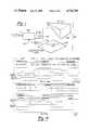
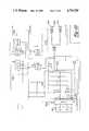
- FIG. 1is a schematic diagram, showing the modifications to an existing video display terminal which are required when placing the apparatus according to one aspect of the invention into service. This figure also shows the structure of the overall apparatus according to a second aspect of the invention;
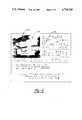
- FIG. 2shows an example of the display of combined pictorial and alphanumeric information on a video display terminal according to the present invention
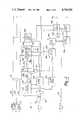
- FIG. 3is a block diagram, showing the flow of and interrelationships among the signals and circuits in the apparatus of the preferred embodiment
- FIG. 4is a timing diagram to explain the sequencing of signals which exist in the apparatus of the preferred embodiment.
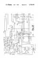
- FIGS. 5A to 5Eare schematic diagrams showing the layout of the apparatus of the preferred embodiment.
- FIG. 1shows, in block diagram form, an embodiment of the invention to comprise a video display terminal (VDT) 100, the major components of which are a monitor 102 and a logic board 104.
- VDT 100creates an alphanumeric video signal on line 106, which is sent to monitor 102 for display.
- logic circuitry 108is added to receive the alphanumeric video signal over line 106 and line 106 is broken at point 110.
- Synchronization signalsare transmitted from circuitry board 104 to circuit 108 over line 112. These synchronization signals include vertical and horizontal synchronization and a dot clock signal.
- Logic circuitry 108receives digitally-encoded pictorial information on line 114. In response to the video signals received over line 106, synchronization signals received over line 112, and pictorial information received over line 114, logic circuit 108 creates a mixed video signal which is sent over line 116. In addition to simply modifying an existing VDT 100 to include logic circuitry 108, an entire VDT incorporating these features may be built.
- FIG. 2 of the drawingsone may see an example of the display provided by a VDT incorporating the logic circuit 108 (in FIG. 1). Shown is a concurrent display of pictorial and alphanumeric information.
- the entire image 200 displayed on monitor 102 of the apparatus shown in FIG. 1contains pictorial information 202, the balance of the display being alphanumeric information 204.
- pictorial information 202has a much higher resolution than alphanumeric information 204.
- each picture element in pictorial information 202can be of a different intensity creating a shading effect which improves the presentation of the information.
- a raster-scan video display terminalrequires four signals: dot clock signal 300, vertical and horizontal synchronization signals 302 and 304 (collectively referred to as 112 in FIG. 1), and terminal video signal 106. They are also provided to apparatus 108, which is interposed between the raster scan signal source, logic circuit 104 (in FIG. 1), and monitor 102 (in FIG. 1).
- serial data line 114The data representing the pictorial information which is to be presented is received in serial fashion on serial data line 114. These serial representations are converted to a parallel form through serial-to-parallel converter 312. Convertor 312 produces a timing signal F on line 314 which is sent to both a clock select circuit 316 and an AND gate 318.
- Converter 312also provides its parallel data to three devices.
- One deviceis command recognizer 320 which scans these parallel data for the occurrence of a command, preceding the pictorial information, which changes the mode of apparatus 108.
- the parallel signalsare also sent to command latch 322 which, when appropriately driven by command recognizer 320, captures the data from converter 312 as a command.
- the data from converter 312is also presented to the third device, picture data buffer 324, which will be further described below.
- Command recognizer 320produces two signals. One signal drives command latch 322 upon recognizing a command. On this same event command recognizer 320 sends a signal I over line 325 to mode latch 326 which, in turn, puts apparatus 108 into its "load” mode, from its "display” mode. This is shown in the upper half of FIG. 4.
- device 108In the "load” mode, device 108 is set to accept pictorial information over serial data line 114, placing it in picture memory 354 for subsequent display.
- command latch 322After receiving a signal from command recognizer 320, which places apparatus 108 in "load” mode, command latch 322 sends a signal to the row count component 328 of address count circuit 330. It also sends a signal to display clock rate select device 332, to the printer control device (not shown), and to video select device 334.
- Picture data buffer 324accepts parallel representations of picture data, the buffer storing the pictorial information until the address count device 330 has designated a selected location in picture memory 354. Upon this event, data are transferred from picture data buffer 324 to the appropriate picture element (pixel) in picture memory 354.
- Mode latch 326produces a signal on line 336 when mode latch 326 is ready to cause the loading of data from serial-to-parallel convertor 312 into appropriate locations in picture memory 354. Passing the signals on lines 114 and 336 through AND gate 318 assures that both the proper mode (as signified by the signal on line 336) and the timing (signal F on line 314) are present before picture memory 154 will store data.
- timing signal F on line 314is characterized by a pulse occurring each time a new set of serial data is converted to parallel form by serial-to-parallel converter 311. These pulses are sent to clock select 316, whose state causes signal J on line 327 to be pulses in synchronism with the pulses in signal F. This is shown in the lower portion of the timing diagram in FIG. 4.
- This clock select signal 327drives address count device 330 which, in turn, controls the loading of data into picture memory 354. Noting that the clock select signal is coordinated with horizontal sync signal 104 and vertical sync signal 102 by address count device 130, address count device 130 can produce proper addresses for appropriately driving the picture memory 154.
- Row count component 328 of address count device 330produces a pulsed signal I on line 331 when its count exceeds the number of rows to be displayed on the VDT. As shown in the lower portion of FIG. 4, this causes mode latch 326 to change its state from the "load” mode to the "display” mode.
- Address count device 330produces a sequence of addresses which are sent over bus 333, facilitating storage of data contained in picture data buffer 324 into the appropriate locations in picture memory 354.
- device 108In the "display" mode, device 108 is set to display the pictorial information data stored in picture memory 354, the alphanumeric character representations which are received in the form of terminal video signal 106, or some concurrent combination thereof.
- the formatis controlled by commands received through serial data line 114. These commands are recognized and latched by command recognizer 320 and command latch 322 and thereby control clock select 316, address count 330, display clock rate select 332, and video select 334.
- model latch 326forces clock select 316 to produce the series of pulses in signal J on line 327 for address count 330 in response to the signal K sent over line 335 by display clock rate select 332. This is shown in the upper portion of FIG. 4.
- Command latch 322provides display clock rate 332 and video select 334 with signals controlling the size and location of the display of the pictorial information.
- Video select 334determines whether the video monitor will be sent the terminal video signal 106 or the analog signal produced by digital-to-analog (D/A) converter 342.
- the digital data sent to D/A converter 342is produced, under control of display clock rate select device 332, from picture memory 354 through data latch 340.
- Data from data latch 340is also sent to printer interface 356, which converts the data to a form suitable for display by a printer.
- Video select 358controls whether terminal video signal 106 or the converted pictorial information produced by printer interface 356 will be passed through to the printer.
- Apparatus 108is maintained in "display" mode until another command to receive pictorial information is received by command recognizer 320 through serial data line 114 and serial-to-parallel converter 312.
- serial data received on line 114is received by an RS-232 quadline receiver 500, which sends data to UART 502. Together, receiver 500 and UART 502 compose serial-to-parallel converter 312. Converter 312 produces parallel data 504, which is sent to command recognizer 320, command latch 322 and picture data buffer 324.
- Command recognizer 320consists of NAND gate 506, flip-flops 508, 510, 512 and dual one shot device 514.
- Command latch 322which receives a signal from command recognizer 520 over line 516, and also receives parallel data over lines 518, consists of a 74LS75 quad latch.
- Picture data buffer 324receiving parallel signals over lines 504, is composed of two octal inverter bus/line drivers, such as a 74LS240.
- Mode latch 326consists of a 74LS74 flip-flop receiving signal L (shown in FIG. 4) on line 325 and signal I (in FIG. 4) on line 331.
- Quad select 316is a 74LS157 quad 2/1 multiplexer which produces signal J (in FIG. 4) on line 327.
- Quad select 316receives signal K (in FIG. 4) on line 335.
- row count 328is composed of two 4-bit up/down binary counters, consisting of 74LS193's.
- column count 520is composed of two 74LS193's.
- FIG. 5C of the drawingsshows picture memory 354 which comprises ten 6116 2,048 by 8-bit CMOS RAM chips, and a BCD to decimal decoder 522, such as a 74LS42.
- Picture memory 354receives a signal from gate 318 over line 524, address data over lines 333, and the picture data from picture data buffer 324 over lines 526.
- data latch 340receives data from picture memory 354 over lines 526.
- Data latch 340is an octal D flip-flop, such as a 74LS374.
- Ditigal to analog converter 342receives data from data latch 340 over lines 528.
- Converter 34comprises two octal inverting bus/line drivers, such as 74LS240's and a network of resistors.
- Video select I 334receives signals from digital to analog converter 342, as well as address count 330 (on lines 530 and 532) command latch 322 (on line 534).
- printer interface 356comprises circuitry for preparing a serial video signal for use by a printer. It receives signals on lines 528, passing its output to video select 358 over line 536.
- Printer interface 356comprises interface chips such as 2716 and 74LS166 along with circuitry comprising multiplexers (74LS157) and flip-flops (74LS74).
- Video select II 358comprises a quad 2/1 multiplexer, such as a 74LS157 along with a NAND gate.
- Display clock rate select device 332is subdivided in FIG. 5.
- One part, 332a,is shown in FIG. 5D and a second part, 332b, is shown in FIG. 5E.
- device 332bproduces clock signals in response to a terminal clock signal received from an external source.
- the clock signalis passed to device 332a on FIG. 5D where it drives a 4-bit up/down binary counter (a 74LS193), whose output drives a dual 2/1 multiplexer 540.
- These devicesproduce the display dot clock signal on line 335 which is used to drive clock select 316. It also produces a latch data signal which is used by data latch 340.
- FIG. 5Ealso discloses blanking circuit 542 comprising commonly-found logic gates and dual D flip-flop devices 544 (such as 74LS74s). The purpose of this circuit is to provide a blanking signal to printer interface 356, to disable outputs on the printer video signal produced by video select 358.
Landscapes
- Engineering & Computer Science (AREA)
- Multimedia (AREA)
- Signal Processing (AREA)
- Physics & Mathematics (AREA)
- Computer Hardware Design (AREA)
- General Physics & Mathematics (AREA)
- Theoretical Computer Science (AREA)
- Controls And Circuits For Display Device (AREA)
Abstract
Description
Claims (16)
Priority Applications (1)
| Application Number | Priority Date | Filing Date | Title |
|---|---|---|---|
| US06/745,441US4734769A (en) | 1985-06-17 | 1985-06-17 | Method and apparatus for display of variable intensity pictures on a video display terminal |
Applications Claiming Priority (1)
| Application Number | Priority Date | Filing Date | Title |
|---|---|---|---|
| US06/745,441US4734769A (en) | 1985-06-17 | 1985-06-17 | Method and apparatus for display of variable intensity pictures on a video display terminal |
Publications (1)
| Publication Number | Publication Date |
|---|---|
| US4734769Atrue US4734769A (en) | 1988-03-29 |
Family
ID=24996692
Family Applications (1)
| Application Number | Title | Priority Date | Filing Date |
|---|---|---|---|
| US06/745,441Expired - LifetimeUS4734769A (en) | 1985-06-17 | 1985-06-17 | Method and apparatus for display of variable intensity pictures on a video display terminal |
Country Status (1)
| Country | Link |
|---|---|
| US (1) | US4734769A (en) |
Cited By (20)
| Publication number | Priority date | Publication date | Assignee | Title |
|---|---|---|---|---|
| US5157736A (en)* | 1991-04-19 | 1992-10-20 | International Business Machines Corporation | Apparatus and method for optical recognition of chemical graphics |
| US5293313A (en)* | 1990-11-21 | 1994-03-08 | Picker International, Inc. | Real time physician view box |
| US5345516A (en)* | 1991-04-19 | 1994-09-06 | International Business Machines Corporation | Apparatus and method for parsing a chemical string |
| US6028599A (en)* | 1994-08-31 | 2000-02-22 | Yuen; Henry C. | Database for use in method and apparatus for displaying television programs and related text |
| US20080127263A1 (en)* | 1996-05-03 | 2008-05-29 | Brian Lee Klosterman | Method and system for displaying advertisements in an electronic program guide |
| US20080178223A1 (en)* | 1994-08-31 | 2008-07-24 | Kwoh Daniel S | Method and apparatus for displaying television programs and related text |
| US7814421B2 (en) | 1998-05-19 | 2010-10-12 | United Video Properties, Inc. | Program guide system with video window browsing |
| US8336071B2 (en) | 1996-12-19 | 2012-12-18 | Gemstar Development Corporation | System and method for modifying advertisement responsive to EPG information |
| US8832742B2 (en) | 2006-10-06 | 2014-09-09 | United Video Properties, Inc. | Systems and methods for acquiring, categorizing and delivering media in interactive media guidance applications |
| US8863170B2 (en) | 2000-03-31 | 2014-10-14 | United Video Properties, Inc. | System and method for metadata-linked advertisements |
| US8918807B2 (en) | 1997-07-21 | 2014-12-23 | Gemstar Development Corporation | System and method for modifying advertisement responsive to EPG information |
| US8931008B2 (en) | 1999-06-29 | 2015-01-06 | United Video Properties, Inc. | Promotional philosophy for a video-on-demand-related interactive display within an interactive television application |
| US9015750B2 (en) | 1998-05-15 | 2015-04-21 | Rovi Guides, Inc. | Interactive television program guide system for determining user values for demographic categories |
| US9075861B2 (en) | 2006-03-06 | 2015-07-07 | Veveo, Inc. | Methods and systems for segmenting relative user preferences into fine-grain and coarse-grain collections |
| US9166714B2 (en) | 2009-09-11 | 2015-10-20 | Veveo, Inc. | Method of and system for presenting enriched video viewing analytics |
| US9319735B2 (en) | 1995-06-07 | 2016-04-19 | Rovi Guides, Inc. | Electronic television program guide schedule system and method with data feed access |
| US9326025B2 (en) | 2007-03-09 | 2016-04-26 | Rovi Technologies Corporation | Media content search results ranked by popularity |
| US9426509B2 (en) | 1998-08-21 | 2016-08-23 | Rovi Guides, Inc. | Client-server electronic program guide |
| US9736524B2 (en) | 2011-01-06 | 2017-08-15 | Veveo, Inc. | Methods of and systems for content search based on environment sampling |
| US9749693B2 (en) | 2006-03-24 | 2017-08-29 | Rovi Guides, Inc. | Interactive media guidance application with intelligent navigation and display features |
Citations (9)
| Publication number | Priority date | Publication date | Assignee | Title |
|---|---|---|---|---|
| US3712956A (en)* | 1971-02-24 | 1973-01-23 | J Lemelson | Information system |
| US4139860A (en)* | 1976-06-25 | 1979-02-13 | Itt Industries, Inc. | Television receiver equipped for simultaneously showing several programs |
| US4178613A (en)* | 1976-10-05 | 1979-12-11 | Nippon Electric Co., Ltd. | Television picture special effects system using digital memory techniques |
| US4205340A (en)* | 1976-10-27 | 1980-05-27 | Nippon Electric Co., Ltd. | Circuit for making a CRT display a TV picture for a copy with dots superposed on half-tone picture areas |
| US4288809A (en)* | 1979-05-23 | 1981-09-08 | Sony Corporation | Television receiver apparatus for selectively displaying a video picture or alphanumeric data information |
| US4450442A (en)* | 1980-12-26 | 1984-05-22 | Matsushita Electric Industrial Co., Ltd. | Display processor for superimposed-picture display system |
| US4498098A (en)* | 1982-06-02 | 1985-02-05 | Digital Equipment Corporation | Apparatus for combining a video signal with graphics and text from a computer |
| US4530009A (en)* | 1980-11-20 | 1985-07-16 | Kabushiki Kaisha Kobe Seiko Sho | Image information synthesizing terminal equipment |
| US4597005A (en)* | 1984-04-26 | 1986-06-24 | Canadian Patents And Development Limited | Digital color photographic image video display system |
- 1985
- 1985-06-17USUS06/745,441patent/US4734769A/ennot_activeExpired - Lifetime
Patent Citations (9)
| Publication number | Priority date | Publication date | Assignee | Title |
|---|---|---|---|---|
| US3712956A (en)* | 1971-02-24 | 1973-01-23 | J Lemelson | Information system |
| US4139860A (en)* | 1976-06-25 | 1979-02-13 | Itt Industries, Inc. | Television receiver equipped for simultaneously showing several programs |
| US4178613A (en)* | 1976-10-05 | 1979-12-11 | Nippon Electric Co., Ltd. | Television picture special effects system using digital memory techniques |
| US4205340A (en)* | 1976-10-27 | 1980-05-27 | Nippon Electric Co., Ltd. | Circuit for making a CRT display a TV picture for a copy with dots superposed on half-tone picture areas |
| US4288809A (en)* | 1979-05-23 | 1981-09-08 | Sony Corporation | Television receiver apparatus for selectively displaying a video picture or alphanumeric data information |
| US4530009A (en)* | 1980-11-20 | 1985-07-16 | Kabushiki Kaisha Kobe Seiko Sho | Image information synthesizing terminal equipment |
| US4450442A (en)* | 1980-12-26 | 1984-05-22 | Matsushita Electric Industrial Co., Ltd. | Display processor for superimposed-picture display system |
| US4498098A (en)* | 1982-06-02 | 1985-02-05 | Digital Equipment Corporation | Apparatus for combining a video signal with graphics and text from a computer |
| US4597005A (en)* | 1984-04-26 | 1986-06-24 | Canadian Patents And Development Limited | Digital color photographic image video display system |
Cited By (39)
| Publication number | Priority date | Publication date | Assignee | Title |
|---|---|---|---|---|
| US5293313A (en)* | 1990-11-21 | 1994-03-08 | Picker International, Inc. | Real time physician view box |
| US5157736A (en)* | 1991-04-19 | 1992-10-20 | International Business Machines Corporation | Apparatus and method for optical recognition of chemical graphics |
| US5345516A (en)* | 1991-04-19 | 1994-09-06 | International Business Machines Corporation | Apparatus and method for parsing a chemical string |
| US6028599A (en)* | 1994-08-31 | 2000-02-22 | Yuen; Henry C. | Database for use in method and apparatus for displaying television programs and related text |
| US6239794B1 (en) | 1994-08-31 | 2001-05-29 | E Guide, Inc. | Method and system for simultaneously displaying a television program and information about the program |
| US6477705B1 (en) | 1994-08-31 | 2002-11-05 | Gemstar Development Corporation | Method and apparatus for transmitting, storing, and processing electronic program guide data for on-screen display |
| US20080178223A1 (en)* | 1994-08-31 | 2008-07-24 | Kwoh Daniel S | Method and apparatus for displaying television programs and related text |
| US20110167451A1 (en)* | 1994-08-31 | 2011-07-07 | Gemstar Development Corporation | Method and apparatus for transmitting, storing and processing electronic program guide data for on-screen display |
| US7996864B2 (en) | 1994-08-31 | 2011-08-09 | Gemstar Development Corporation | Method and apparatus for displaying television programs and related text |
| US9319735B2 (en) | 1995-06-07 | 2016-04-19 | Rovi Guides, Inc. | Electronic television program guide schedule system and method with data feed access |
| US20080127263A1 (en)* | 1996-05-03 | 2008-05-29 | Brian Lee Klosterman | Method and system for displaying advertisements in an electronic program guide |
| US8776125B2 (en) | 1996-05-03 | 2014-07-08 | Starsight Telecast Inc. | Method and system for displaying advertisements in an electronic program guide |
| US8869204B2 (en) | 1996-05-03 | 2014-10-21 | Starsight Telecast, Inc. | Method and system for displaying advertisements in an electronic program guide |
| US8635649B2 (en) | 1996-12-19 | 2014-01-21 | Gemstar Development Corporation | System and method for modifying advertisement responsive to EPG information |
| US8336071B2 (en) | 1996-12-19 | 2012-12-18 | Gemstar Development Corporation | System and method for modifying advertisement responsive to EPG information |
| US8726311B2 (en) | 1996-12-19 | 2014-05-13 | Gemstar Development Corporation | System and method for modifying advertisement responsive to EPG information |
| US8732757B2 (en) | 1996-12-19 | 2014-05-20 | Gemstar Development Corporation | System and method for targeted advertisement display responsive to user characteristics |
| US8448209B2 (en) | 1996-12-19 | 2013-05-21 | Gemstar Development Corporation | System and method for displaying advertisements responsive to EPG information |
| US9191722B2 (en) | 1997-07-21 | 2015-11-17 | Rovi Guides, Inc. | System and method for modifying advertisement responsive to EPG information |
| US8918807B2 (en) | 1997-07-21 | 2014-12-23 | Gemstar Development Corporation | System and method for modifying advertisement responsive to EPG information |
| US9015749B2 (en) | 1997-07-21 | 2015-04-21 | Rovi Guides, Inc. | System and method for modifying advertisement responsive to EPG information |
| US9015750B2 (en) | 1998-05-15 | 2015-04-21 | Rovi Guides, Inc. | Interactive television program guide system for determining user values for demographic categories |
| US9635406B2 (en) | 1998-05-15 | 2017-04-25 | Rovi Guides, Inc. | Interactive television program guide system for determining user values for demographic categories |
| US20110041152A1 (en)* | 1998-05-19 | 2011-02-17 | United Video Properties, Inc. | Program guide system with video window browsing |
| US7814421B2 (en) | 1998-05-19 | 2010-10-12 | United Video Properties, Inc. | Program guide system with video window browsing |
| US9426509B2 (en) | 1998-08-21 | 2016-08-23 | Rovi Guides, Inc. | Client-server electronic program guide |
| US8931008B2 (en) | 1999-06-29 | 2015-01-06 | United Video Properties, Inc. | Promotional philosophy for a video-on-demand-related interactive display within an interactive television application |
| US10015562B2 (en) | 2000-03-31 | 2018-07-03 | Rovi Guides, Inc. | System and method for metadata-linked advertisements |
| US8863170B2 (en) | 2000-03-31 | 2014-10-14 | United Video Properties, Inc. | System and method for metadata-linked advertisements |
| US9128987B2 (en) | 2006-03-06 | 2015-09-08 | Veveo, Inc. | Methods and systems for selecting and presenting content based on a comparison of preference signatures from multiple users |
| US9092503B2 (en) | 2006-03-06 | 2015-07-28 | Veveo, Inc. | Methods and systems for selecting and presenting content based on dynamically identifying microgenres associated with the content |
| US9075861B2 (en) | 2006-03-06 | 2015-07-07 | Veveo, Inc. | Methods and systems for segmenting relative user preferences into fine-grain and coarse-grain collections |
| US10984037B2 (en) | 2006-03-06 | 2021-04-20 | Veveo, Inc. | Methods and systems for selecting and presenting content on a first system based on user preferences learned on a second system |
| US9749693B2 (en) | 2006-03-24 | 2017-08-29 | Rovi Guides, Inc. | Interactive media guidance application with intelligent navigation and display features |
| US8832742B2 (en) | 2006-10-06 | 2014-09-09 | United Video Properties, Inc. | Systems and methods for acquiring, categorizing and delivering media in interactive media guidance applications |
| US9326025B2 (en) | 2007-03-09 | 2016-04-26 | Rovi Technologies Corporation | Media content search results ranked by popularity |
| US10694256B2 (en) | 2007-03-09 | 2020-06-23 | Rovi Technologies Corporation | Media content search results ranked by popularity |
| US9166714B2 (en) | 2009-09-11 | 2015-10-20 | Veveo, Inc. | Method of and system for presenting enriched video viewing analytics |
| US9736524B2 (en) | 2011-01-06 | 2017-08-15 | Veveo, Inc. | Methods of and systems for content search based on environment sampling |
Similar Documents
| Publication | Publication Date | Title |
|---|---|---|
| US4734769A (en) | Method and apparatus for display of variable intensity pictures on a video display terminal | |
| EP0266506B1 (en) | Image display processor for graphics workstation | |
| EP0023217B1 (en) | Data processing system for color graphics display | |
| US4197590A (en) | Method for dynamically viewing image elements stored in a random access memory array | |
| EP0139932B1 (en) | Apparatus for generating the display of a cursor | |
| US4814756A (en) | Video display control system having improved storage of alphanumeric and graphic display data | |
| US4684936A (en) | Displays having different resolutions for alphanumeric and graphics data | |
| US4284988A (en) | Control means to provide slow scrolling positioning and spacing in a digital video display system | |
| EP0034600A4 (en) | Video display terminal having means for altering data words. | |
| US4328557A (en) | Processor circuit for video data terminal | |
| JPS60189789A (en) | Display unit | |
| US4570161A (en) | Raster scan digital display system | |
| GB1136302A (en) | Method and apparatus for converting digital character codes to video signals for producing visual information on a display screen | |
| US4158200A (en) | Digital video display system with a plurality of gray-scale levels | |
| US3895375A (en) | Display apparatus with facility for underlining and striking out characters | |
| US4409591A (en) | Variable size character generator | |
| US4720803A (en) | Display control apparatus for performing multicolor display by tiling display | |
| US4834374A (en) | Object image indicating apparatus | |
| US4513278A (en) | Video Synthesizer for a digital video display system employing a plurality of grayscale levels displayed in discrete steps of luminance | |
| US4205310A (en) | Television titling apparatus and method | |
| CA1335215C (en) | Flat panel display attribute generator | |
| US5107255A (en) | Control device for a display apparatus | |
| US4952921A (en) | Graphic dot flare apparatus | |
| US3803584A (en) | Display system | |
| US3787833A (en) | Upshift control for video display |
Legal Events
| Date | Code | Title | Description |
|---|---|---|---|
| AS | Assignment | Owner name:PROFESSIONAL GUIDANCE SYSTEMS, INC., 111 HOLLISTER Free format text:ASSIGNMENT OF ASSIGNORS INTEREST.;ASSIGNOR:DAVIS, MARK A.;REEL/FRAME:004418/0685 Effective date:19850606 Owner name:PROFESSIONAL GUIDANCE SYSTEMS, INC., A CORP. OF MI Free format text:ASSIGNMENT OF ASSIGNORS INTEREST;ASSIGNOR:DAVIS, MARK A.;REEL/FRAME:004418/0685 Effective date:19850606 | |
| FEPP | Fee payment procedure | Free format text:PAYOR NUMBER ASSIGNED (ORIGINAL EVENT CODE: ASPN); ENTITY STATUS OF PATENT OWNER: LARGE ENTITY | |
| FPAY | Fee payment | Year of fee payment:4 | |
| REMI | Maintenance fee reminder mailed | ||
| FEPP | Fee payment procedure | Free format text:PETITION RELATED TO MAINTENANCE FEES FILED (ORIGINAL EVENT CODE: PMFP); ENTITY STATUS OF PATENT OWNER: LARGE ENTITY | |
| FP | Lapsed due to failure to pay maintenance fee | Effective date:19960403 | |
| SULP | Surcharge for late payment | ||
| FEPP | Fee payment procedure | Free format text:PETITION RELATED TO MAINTENANCE FEES FILED (ORIGINAL EVENT CODE: PMFP); ENTITY STATUS OF PATENT OWNER: LARGE ENTITY | |
| FEPP | Fee payment procedure | Free format text:PETITION RELATED TO MAINTENANCE FEES DENIED/DISMISSED (ORIGINAL EVENT CODE: PMFD); ENTITY STATUS OF PATENT OWNER: LARGE ENTITY | |
| FPAY | Fee payment | Year of fee payment:8 | |
| SULP | Surcharge for late payment | ||
| AS | Assignment | Owner name:MOORE U.S.A. INC., NEW YORK Free format text:ASSIGNMENT OF ASSIGNORS INTEREST;ASSIGNOR:PROFESSIONAL GUIDANCE SYSTEMS, INC.;REEL/FRAME:008800/0193 Effective date:19971103 | |
| FEPP | Fee payment procedure | Free format text:PETITION RELATED TO MAINTENANCE FEES GRANTED (ORIGINAL EVENT CODE: PMFG); ENTITY STATUS OF PATENT OWNER: LARGE ENTITY | |
| PRDP | Patent reinstated due to the acceptance of a late maintenance fee | Effective date:19970912 | |
| STCF | Information on status: patent grant | Free format text:PATENTED CASE | |
| PRDP | Patent reinstated due to the acceptance of a late maintenance fee | Effective date:19980320 | |
| FEPP | Fee payment procedure | Free format text:PAT HLDR NO LONGER CLAIMS SMALL ENT STAT AS SMALL BUSINESS (ORIGINAL EVENT CODE: LSM2); ENTITY STATUS OF PATENT OWNER: LARGE ENTITY | |
| FPAY | Fee payment | Year of fee payment:12 | |
| AS | Assignment | Owner name:MOORE NORTH AMERICA INC., ILLINOIS Free format text:SECURITY INTEREST;ASSIGNOR:VISTA DMS, INC.;REEL/FRAME:010567/0411 Effective date:19991217 Owner name:MOORE CORPORATION LIMITED, CANADA Free format text:SECURITY INTEREST;ASSIGNOR:VISTA DMS, INC.;REEL/FRAME:010567/0411 Effective date:19991217 | |
| AS | Assignment | Owner name:VISTA DMS, INC., CALIFORNIA Free format text:ASSIGNMENT OF ASSIGNORS INTEREST;ASSIGNOR:MOORE NORTH AMERICA, INC.;REEL/FRAME:010589/0285 Effective date:19991217 |