US4734184A - Self-activating hydratable solid-state electrode apparatus - Google Patents
Self-activating hydratable solid-state electrode apparatusDownload PDFInfo
- Publication number
- US4734184A US4734184AUS07/021,520US2152087AUS4734184AUS 4734184 AUS4734184 AUS 4734184AUS 2152087 AUS2152087 AUS 2152087AUS 4734184 AUS4734184 AUS 4734184A
- Authority
- US
- United States
- Prior art keywords
- electrode
- flow channel
- layer
- well
- solution
- Prior art date
- Legal status (The legal status is an assumption and is not a legal conclusion. Google has not performed a legal analysis and makes no representation as to the accuracy of the status listed.)
- Expired - Fee Related
Links
Images


Classifications
- G—PHYSICS
- G01—MEASURING; TESTING
- G01N—INVESTIGATING OR ANALYSING MATERIALS BY DETERMINING THEIR CHEMICAL OR PHYSICAL PROPERTIES
- G01N33/00—Investigating or analysing materials by specific methods not covered by groups G01N1/00 - G01N31/00
- G01N33/48—Biological material, e.g. blood, urine; Haemocytometers
- G01N33/483—Physical analysis of biological material
- G01N33/487—Physical analysis of biological material of liquid biological material
- G01N33/49—Blood
- G01N33/4915—Blood using flow cells
- A—HUMAN NECESSITIES
- A61—MEDICAL OR VETERINARY SCIENCE; HYGIENE
- A61B—DIAGNOSIS; SURGERY; IDENTIFICATION
- A61B5/00—Measuring for diagnostic purposes; Identification of persons
- A61B5/145—Measuring characteristics of blood in vivo, e.g. gas concentration or pH-value ; Measuring characteristics of body fluids or tissues, e.g. interstitial fluid or cerebral tissue
- A61B5/14535—Measuring characteristics of blood in vivo, e.g. gas concentration or pH-value ; Measuring characteristics of body fluids or tissues, e.g. interstitial fluid or cerebral tissue for measuring haematocrit
- A—HUMAN NECESSITIES
- A61—MEDICAL OR VETERINARY SCIENCE; HYGIENE
- A61B—DIAGNOSIS; SURGERY; IDENTIFICATION
- A61B5/00—Measuring for diagnostic purposes; Identification of persons
- A61B5/145—Measuring characteristics of blood in vivo, e.g. gas concentration or pH-value ; Measuring characteristics of body fluids or tissues, e.g. interstitial fluid or cerebral tissue
- A61B5/14539—Measuring characteristics of blood in vivo, e.g. gas concentration or pH-value ; Measuring characteristics of body fluids or tissues, e.g. interstitial fluid or cerebral tissue for measuring pH
- A—HUMAN NECESSITIES
- A61—MEDICAL OR VETERINARY SCIENCE; HYGIENE
- A61B—DIAGNOSIS; SURGERY; IDENTIFICATION
- A61B5/00—Measuring for diagnostic purposes; Identification of persons
- A61B5/145—Measuring characteristics of blood in vivo, e.g. gas concentration or pH-value ; Measuring characteristics of body fluids or tissues, e.g. interstitial fluid or cerebral tissue
- A61B5/14542—Measuring characteristics of blood in vivo, e.g. gas concentration or pH-value ; Measuring characteristics of body fluids or tissues, e.g. interstitial fluid or cerebral tissue for measuring blood gases
- A—HUMAN NECESSITIES
- A61—MEDICAL OR VETERINARY SCIENCE; HYGIENE
- A61B—DIAGNOSIS; SURGERY; IDENTIFICATION
- A61B5/00—Measuring for diagnostic purposes; Identification of persons
- A61B5/145—Measuring characteristics of blood in vivo, e.g. gas concentration or pH-value ; Measuring characteristics of body fluids or tissues, e.g. interstitial fluid or cerebral tissue
- A61B5/1455—Measuring characteristics of blood in vivo, e.g. gas concentration or pH-value ; Measuring characteristics of body fluids or tissues, e.g. interstitial fluid or cerebral tissue using optical sensors, e.g. spectral photometrical oximeters
- A61B5/14551—Measuring characteristics of blood in vivo, e.g. gas concentration or pH-value ; Measuring characteristics of body fluids or tissues, e.g. interstitial fluid or cerebral tissue using optical sensors, e.g. spectral photometrical oximeters for measuring blood gases
- A61B5/14557—Measuring characteristics of blood in vivo, e.g. gas concentration or pH-value ; Measuring characteristics of body fluids or tissues, e.g. interstitial fluid or cerebral tissue using optical sensors, e.g. spectral photometrical oximeters for measuring blood gases specially adapted to extracorporeal circuits
- A—HUMAN NECESSITIES
- A61—MEDICAL OR VETERINARY SCIENCE; HYGIENE
- A61B—DIAGNOSIS; SURGERY; IDENTIFICATION
- A61B5/00—Measuring for diagnostic purposes; Identification of persons
- A61B5/145—Measuring characteristics of blood in vivo, e.g. gas concentration or pH-value ; Measuring characteristics of body fluids or tissues, e.g. interstitial fluid or cerebral tissue
- A61B5/1468—Measuring characteristics of blood in vivo, e.g. gas concentration or pH-value ; Measuring characteristics of body fluids or tissues, e.g. interstitial fluid or cerebral tissue using chemical or electrochemical methods, e.g. by polarographic means
- A—HUMAN NECESSITIES
- A61—MEDICAL OR VETERINARY SCIENCE; HYGIENE
- A61M—DEVICES FOR INTRODUCING MEDIA INTO, OR ONTO, THE BODY; DEVICES FOR TRANSDUCING BODY MEDIA OR FOR TAKING MEDIA FROM THE BODY; DEVICES FOR PRODUCING OR ENDING SLEEP OR STUPOR
- A61M1/00—Suction or pumping devices for medical purposes; Devices for carrying-off, for treatment of, or for carrying-over, body-liquids; Drainage systems
- A61M1/36—Other treatment of blood in a by-pass of the natural circulatory system, e.g. temperature adaptation, irradiation ; Extra-corporeal blood circuits
- A61M1/3621—Extra-corporeal blood circuits
- A61M1/3622—Extra-corporeal blood circuits with a cassette forming partially or totally the blood circuit
- A61M1/36224—Extra-corporeal blood circuits with a cassette forming partially or totally the blood circuit with sensing means or components thereof
- A—HUMAN NECESSITIES
- A61—MEDICAL OR VETERINARY SCIENCE; HYGIENE
- A61M—DEVICES FOR INTRODUCING MEDIA INTO, OR ONTO, THE BODY; DEVICES FOR TRANSDUCING BODY MEDIA OR FOR TAKING MEDIA FROM THE BODY; DEVICES FOR PRODUCING OR ENDING SLEEP OR STUPOR
- A61M1/00—Suction or pumping devices for medical purposes; Devices for carrying-off, for treatment of, or for carrying-over, body-liquids; Drainage systems
- A61M1/36—Other treatment of blood in a by-pass of the natural circulatory system, e.g. temperature adaptation, irradiation ; Extra-corporeal blood circuits
- A61M1/3621—Extra-corporeal blood circuits
- A61M1/3622—Extra-corporeal blood circuits with a cassette forming partially or totally the blood circuit
- A61M1/36225—Extra-corporeal blood circuits with a cassette forming partially or totally the blood circuit with blood pumping means or components thereof
- A—HUMAN NECESSITIES
- A61—MEDICAL OR VETERINARY SCIENCE; HYGIENE
- A61M—DEVICES FOR INTRODUCING MEDIA INTO, OR ONTO, THE BODY; DEVICES FOR TRANSDUCING BODY MEDIA OR FOR TAKING MEDIA FROM THE BODY; DEVICES FOR PRODUCING OR ENDING SLEEP OR STUPOR
- A61M1/00—Suction or pumping devices for medical purposes; Devices for carrying-off, for treatment of, or for carrying-over, body-liquids; Drainage systems
- A61M1/36—Other treatment of blood in a by-pass of the natural circulatory system, e.g. temperature adaptation, irradiation ; Extra-corporeal blood circuits
- A61M1/3621—Extra-corporeal blood circuits
- A61M1/3622—Extra-corporeal blood circuits with a cassette forming partially or totally the blood circuit
- A61M1/36226—Constructional details of cassettes, e.g. specific details on material or shape
- A61M1/362265—Details of valves
- A—HUMAN NECESSITIES
- A61—MEDICAL OR VETERINARY SCIENCE; HYGIENE
- A61M—DEVICES FOR INTRODUCING MEDIA INTO, OR ONTO, THE BODY; DEVICES FOR TRANSDUCING BODY MEDIA OR FOR TAKING MEDIA FROM THE BODY; DEVICES FOR PRODUCING OR ENDING SLEEP OR STUPOR
- A61M1/00—Suction or pumping devices for medical purposes; Devices for carrying-off, for treatment of, or for carrying-over, body-liquids; Drainage systems
- A61M1/36—Other treatment of blood in a by-pass of the natural circulatory system, e.g. temperature adaptation, irradiation ; Extra-corporeal blood circuits
- A61M1/3621—Extra-corporeal blood circuits
- A61M1/367—Circuit parts not covered by the preceding subgroups of group A61M1/3621
- G—PHYSICS
- G01—MEASURING; TESTING
- G01N—INVESTIGATING OR ANALYSING MATERIALS BY DETERMINING THEIR CHEMICAL OR PHYSICAL PROPERTIES
- G01N33/00—Investigating or analysing materials by specific methods not covered by groups G01N1/00 - G01N31/00
- G01N33/48—Biological material, e.g. blood, urine; Haemocytometers
- G01N33/483—Physical analysis of biological material
- G01N33/487—Physical analysis of biological material of liquid biological material
- G01N33/49—Blood
- G01N33/492—Determining multiple analytes
- A—HUMAN NECESSITIES
- A61—MEDICAL OR VETERINARY SCIENCE; HYGIENE
- A61M—DEVICES FOR INTRODUCING MEDIA INTO, OR ONTO, THE BODY; DEVICES FOR TRANSDUCING BODY MEDIA OR FOR TAKING MEDIA FROM THE BODY; DEVICES FOR PRODUCING OR ENDING SLEEP OR STUPOR
- A61M1/00—Suction or pumping devices for medical purposes; Devices for carrying-off, for treatment of, or for carrying-over, body-liquids; Drainage systems
- A61M1/36—Other treatment of blood in a by-pass of the natural circulatory system, e.g. temperature adaptation, irradiation ; Extra-corporeal blood circuits
- A61M1/3621—Extra-corporeal blood circuits
- A61M1/3622—Extra-corporeal blood circuits with a cassette forming partially or totally the blood circuit
- A61M1/36222—Details related to the interface between cassette and machine
- A—HUMAN NECESSITIES
- A61—MEDICAL OR VETERINARY SCIENCE; HYGIENE
- A61M—DEVICES FOR INTRODUCING MEDIA INTO, OR ONTO, THE BODY; DEVICES FOR TRANSDUCING BODY MEDIA OR FOR TAKING MEDIA FROM THE BODY; DEVICES FOR PRODUCING OR ENDING SLEEP OR STUPOR
- A61M2205/00—General characteristics of the apparatus
- A61M2205/12—General characteristics of the apparatus with interchangeable cassettes forming partially or totally the fluid circuit
- A—HUMAN NECESSITIES
- A61—MEDICAL OR VETERINARY SCIENCE; HYGIENE
- A61M—DEVICES FOR INTRODUCING MEDIA INTO, OR ONTO, THE BODY; DEVICES FOR TRANSDUCING BODY MEDIA OR FOR TAKING MEDIA FROM THE BODY; DEVICES FOR PRODUCING OR ENDING SLEEP OR STUPOR
- A61M2230/00—Measuring parameters of the user
- A61M2230/20—Blood composition characteristics
- A61M2230/202—Blood composition characteristics partial carbon oxide pressure, e.g. partial dioxide pressure (P-CO2)
- A—HUMAN NECESSITIES
- A61—MEDICAL OR VETERINARY SCIENCE; HYGIENE
- A61M—DEVICES FOR INTRODUCING MEDIA INTO, OR ONTO, THE BODY; DEVICES FOR TRANSDUCING BODY MEDIA OR FOR TAKING MEDIA FROM THE BODY; DEVICES FOR PRODUCING OR ENDING SLEEP OR STUPOR
- A61M2230/00—Measuring parameters of the user
- A61M2230/20—Blood composition characteristics
- A61M2230/205—Blood composition characteristics partial oxygen pressure (P-O2)
- A—HUMAN NECESSITIES
- A61—MEDICAL OR VETERINARY SCIENCE; HYGIENE
- A61M—DEVICES FOR INTRODUCING MEDIA INTO, OR ONTO, THE BODY; DEVICES FOR TRANSDUCING BODY MEDIA OR FOR TAKING MEDIA FROM THE BODY; DEVICES FOR PRODUCING OR ENDING SLEEP OR STUPOR
- A61M2230/00—Measuring parameters of the user
- A61M2230/20—Blood composition characteristics
- A61M2230/207—Blood composition characteristics hematocrit
- A—HUMAN NECESSITIES
- A61—MEDICAL OR VETERINARY SCIENCE; HYGIENE
- A61M—DEVICES FOR INTRODUCING MEDIA INTO, OR ONTO, THE BODY; DEVICES FOR TRANSDUCING BODY MEDIA OR FOR TAKING MEDIA FROM THE BODY; DEVICES FOR PRODUCING OR ENDING SLEEP OR STUPOR
- A61M2230/00—Measuring parameters of the user
- A61M2230/20—Blood composition characteristics
- A61M2230/208—Blood composition characteristics pH-value
Definitions
- This inventionrelates to solid state electrode or sensor apparatus for measuring certain characteristics of an aqueous sample such as a body fluid or a blood sample and more particularly to such apparatus which employs a disposable cartridge containing a sensor or a bank of sensors for such characteristics and reagents used to calibrate the sensors.
- in-line sensorsAlthough use of in-line sensors minimizes both the risk of contamination during transfer and the risk of delay, these sensors have a response which normally varies or "drifts" during use; moreover, this drift is not at a constant rate.
- Present in-line sensorscan only be calibrated before they are placed in the extracorporeal circuit. Thus, the inherent drift of these in-line sensors cannot be monitored, resulting in readings of ever decreasing reliability as time passes.
- the present inventionis directed to a system which provides quick, on-site contemporaneous blood chemistry analysis, with minimal risk of contamination, and which maintains its accuracy over its useful life.
- the systemcan be operated in an automatic sampling mode presently to be described in detail and also a discrete sampling mode.
- the systemcan be operated in the automatic mode sampling the extracorporeal blood flow of a patient following which, after automatic sampling is discontinued, discrete samples of the patient's blood can be taken.
- a blood chemistry analysis machine forming a preferred embodiment of the present inventionis adapted to be connected to an extracorporeal shunt or an ex vivo blood source such as a heart/lung machine used to sustain a patient during surgery, intensive care, critical care and the like, to allow small test samples of flowing live ex vivo blood to be diverted off-line from either the venous or arterial flow lines of the heart/lung machine directly in real time to a chamber exposed to a bank of solid-state micro-electrodes which generate electrical signals proportional to chemical characteristics of the real time flowing blood sample.
- an extracorporeal shunt or an ex vivo blood sourcesuch as a heart/lung machine used to sustain a patient during surgery, intensive care, critical care and the like
- the bank of electrodesis housed in a disposable cartridge, adjacent to a thermal plate which maintains the test sample at a constant temperature.
- the electrodesUpon insertion of the cartridge into a suitably adapted blood chemistry analysis machine, the electrodes connect to an electrode interface which selects one of the plurality of electrical signals generated by the sensors and passes the selected signal to a microprocessor in the machine where it is converted from analog to digital form suitable for analysis, storage and display.
- a metal plate in the cartridgeconnects to a thermal unit in the machine which monitors the temperature of and generates and transmits heat to the plate and through it to the sample in the adjacent electrode chamber in order to maintain the sample at a constant temperature.
- the cartridgealso contains at least one, and preferably two containers of reference or calibrating electrolyte solution (i.e., solution serving for purposes of quality control including calibration, sometimes referred to hereinafter as calibration solution), as well as a reservoir suitable to collect waste fluids following assay.
- a selection valve in the cartridgeconnects to a shaft in the machine, controlled by the microprocessor, to selectively allow either of the calibrating solutions or the test sample to flow across the electrodes.
- the force driving the fluid flow through the cartridgeis provided by a peristaltic pump formed when a set of rotatable drive rollers in the machine pinch exposed portions of tubing against the curved wall of the pump slot on the cartridge.
- the rotation of the rollersforces either the calibrating solutions or a test sample from their respective sources through the cartridge tubing across the electrode chamber and into the waste collection reservoir.
- the rotation of the drive rollersis controlled by the microprocessor.
- the analysis machinehouses an internal digital clock which provides a time base for the operation of the system, a back-up battery power source, an operator keyboard, a display and a printer.
- the selection valve and drive rollerscooperate to cause the calibrating solution to flow into the electrode chamber where a reading is taken and stored in the microprocessor. Subsequently and in a similar manner, a reading of the test sample is taken, analyzed by the microprocessor and displayed. The assayed fluids are directed into the waste collection reservoir.
- the microprocessorcontrols and repeats this cycle of calibration and test sample assay at a rate preselected and entered by the operator through the control keyboard.
- the keyboardalso allows the operator to take an immediate assay at any time, even while the machine is in its automatic cycle mode, limited only by the recycling time of between two and three minutes. Following surgery, the cartridge and the tubing connecting the venous and arterial flows of the heart-lung machine to the cartridge are discarded and the machine is ready for use with a new cartridge.
- FIG. 1is a schematic diagram showing the major components of a preferred embodiment of a blood gas analysis system
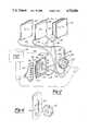
- FIG. 2is an exploded view of one embodiment of elements of a sampling cartridge useful with the system of FIG. 1;
- FIG. 3is an elevated side view of this embodiment of the cartridge showing the insertion end of the cartridge in the foreground;
- FIG. 4is a fragmentary side view of the trailing end of this embodiment of the cartridge
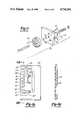
- FIG. 5is an exploded view of the selection valve contained in this embodiment of the cartridge
- FIG. 6is a fragmentary side view of the end wall at the insertion end of this embodiment of the cartridge, showing the peristaltic pump slot;
- FIG. 7is a reverse frontal view of the electrode card, partly fragmentary, contained in this embodiment of the cartridge.
- FIG. 8ais a frontal view of the electrode card contained in this embodiment of the cartridge.
- FIG. 8bis a cross sectional view of this electrode card taken on line 8b--8b of FIG. 8a;
- FIGS. 9, 10 and 11are sectional views taken respectively on line 9--9, line 10--10 and line 11--11 of FIG. 7;
- FIG. 12is a frontal view of one embodiment of the control panel of the blood gas analysis machine showing the display and keyboard.
- a preferred embodiment of the inventionis adapted to measure the unbound concentration, or activity, of two blood gases, oxygen and carbon dioxide, of two ions, potassium and calcium, and of the blood pH and hematocrit.
- Alternative embodiments of the inventionmeasure selected ones of these blood characteristic factors and/or other additional factors.
- the overall systememploys an electrode assembly, generally indicated at 10, incorporating a plurality of solid-state electrodes adapted to make electrical measurements on a blood sample introduced to the electrode assembly.
- Blood samples to be analyzed by the systemare introduced through a conduit 12. These blood samples are preferably derived on a periodic basis from an extracorporeal blood flow circuit connected to a patient during open heart surgery.
- the nature of this extracorporeal circuit and the manner in which blood samples may be introduced into the analysis system of the present inventionis disclosed in co-pending patent application Ser. No. 713,435, filed Mar. 19, 1985 and now abandoned, entitled “Apparatus For Chemical Measurement of Blood Characteristics", assigned to the assignee of the present invention and the disclosure of that co-pending application is incorporated herein by reference.
- blood samplesmay be introduced into the flow line 12 through other automatic means, or manually, as by syringe.
- the blood samplesmay be introduced as discrete samples, as described above.
- the systemincorporates two prepackaged containers 14 and 16 each containing calibrating aqueous solutions having known values of the parameters to be measured by the system.
- the two calibrating solutionshave different known values of each of the measured parameters to allow the system to be calibrated on a 2-point basis.
- the solution contained within the bag 14will be termed Calibrating Solution A and the solution contained within the bag 16 will be referred to as Calibrating Solution B.
- Each of the bags 14 and 16contains a sufficient quantity of its calibrating solution to allow the system to be calibrated a substantial number of times before the cartridge containing the containers must be replaced.
- the container 14is connected to the input of a 3-position valve 18 through a flow line 20 and the container 16 for calibration solution B is connected to a second input of the 3-position valve through a flow line 22.
- the blood sample flow line 12is connected to the third input of the three-position valve.
- the valve 18is adapted to connect one of the input flow lines 12, 20 or 22 to an output flow line 24, depending upon the position of the valve.
- the flow line 24extends to the input of the electrode assembly.
- the systemincludes a third container 28, for a reference solution.
- the container 28is connected to the electrode assembly by a flow line 30.
- the systemfurther includes a fourth container 32 for waste, which receives the blood samples, the calibrating solutions and the reference solution after they have passed through the electrode assembly 10, via a flexible conduit 34 that has input from the electrode assembly.
- Both the waste flow conduit 34 and the reference solution flow line 30consist of or include sections of flexible walled tubing that pass through a peristaltic pump, schematically illustrated at 26.
- the pumpcompresses and strokes the flexible sections of the flow lines 30 and 34 to induce a pressured flow of reference solution from the container 28 to the electrode assembly 10 and to create a negative pressure on the waste products in flow line 24 so as to draw fluids in the flow line 24 through passages in the electrode assembly 10.
- This arrangementas opposed to the alternative of inducing positive pressure on the blood and calibrating solutions to force them through the electrode assembly 10, avoids the imposition of unnecessary and possibly traumatic mechanical forces on the blood sample and minimizes possibilities of leaks in the electrode assembly.
- the system as heretofore described in a preferred embodiment of the present inventionis contained in a disposable cartridge.
- a cartridge of a similar typeis set forth in detail in the co-pending patent application referred to above.
- the present cartridgecontains sufficient quantities of the calibrating solutions and the reference solution to perform analysis of a number of samples of blood. After use, the cartridge is intended to be discarded and replaced with another cartridge.
- the electrode assembly 10has a number of edge connectors 36 in a bank which allow it to be plugged into a female matching connector 38 so that the electrodes formed on the assembly 10 may be connected to an electronic controller 40.
- the electronic controlleris connected to the valve 18 by a line 42 and to the motor of the peristaltic pump 26 by a line 44.
- the controllercontrols the position of the valve 18 and the energization of the pump 26 to cause sequences of blood samples and calibrating solutions to be passed through the electrode assembly.
- the electrodes forming part of the assemblymake measurements of the parameters of the sample and the controller 40 stores these electrical values.
- the controller 40Based upon measurements made during the passage of the calibration solutions through the electrode assembly, and the known values of the measured parameters contained within the calibrating solution, the controller 40 effectively creates a calibration curve for each of the measured parameters so that when a blood sample is passed through the electrode assembly 10 the measurements made by the electrodes can be used to derive accurate measurements of the parameters of interest. These parameters are stored and displayed by the controller 40.
- the controller 40preferably uses a suitably programmed microprocessor to perform measurement, calculation, storage and control functions, all as described in co-pending application referred to previously.
- Containers 14 and 16 for the calibration solutions A and B respectivelyare substantially identical and are prepared in the same manner. Each consists of an envelope formed by heat sealing together the edges of a pair of sheets of thin, flexible aluminum foil coated with plastic resins. The film material of the bags 14 and 16 must be substantially impervious to gases.
- a preferred composition of calibrating solution Aprepared at 37° C. and at atmospheric pressure tonometered with 8% CO 2 -N 2 gas, is as follows:
- a preferred composition for calibration solution Bprepared at 50° C. and at 700 mm. Hg absolute pressure tonometered with 21% O 2 -4% CO 2 -N 2 gas, is as follows:
- compositions of the two calibrating solutionsare chosen so that for each of the characteristics measured by the system a pair of values are obtained that are spaced over the range of permissible values that are measured by the system, providing a balanced 2-point calibration for the instrument.
- the calibration compositionsare prepared by premixing all of the constituents, with the exception of the calcium dihydrate salt, next tonometering the solution with oxygen and CO 2 mixed with nitrogen to produce the desired level of pH for the solution; then adding the calcium salt; and finally retonometering the solution to adjust for any variation in the gas levels which occurred during addition of the calcium salt.
- the temperature and pressure at which the calibrating solutions are prepared and their method of packagingmust be such as to preclude the possibility of dissolved gases going out of solution in the container, which would affect the concentration of gases in the calibrating solutions, and to minimize the tendency for gases to permeate through even the most impermeable materials practically obtainable.
- the calibration solutionsare packaged with the solutions completely filling the containers, so that there is no head space, by evacuating the containers prior to filling in a manner which will be subsequently described.
- the solutionBy filling the calibration solution into an evacuated flexible wall container at elevated temperatures and subatmospheric pressure, the solution will not have any tendency at a lower use temperature to outgas and thus produce gas bubbles in the container. Were outgassing to occur, the concentrations of the gases in the solution would be affected, creating an inaccuracy in the calibration of the instruments.
- the calibration solutionsnot be packaged at too low a pressure i.e., not below about 625 mm of mercury, because the absorptive capacity of the solution for gases conceivably increases as the packaging pressure decreases and below that pressure value the absorptive capacity of the solution may be sufficiently high that it will tend to draw gases in through the slight inherent premeability of even the most gas impervious flexible packaging material, over long periods of time. Accordingly, a packaging pressure in the range of 625-700 mm of mercury is preferred.
- Calibration Solution Ais prepared at a temperature above its intended use temperature at a controlled pressure close to atmospheric pressure. This solution contains no oxygen. The sodium sulfite in the solution serves to remove any residual oxygen from the prepared solution. Through use of elevated temperature (e.g., 37° C.) the solution may be prepared at about atmospheric pressure without any possibility of subsequent microbubbles within the container or gas transfer through the container when packaged in a zero head space flexible gas impervious container.
- elevated temperaturee.g. 37° C.
- the envelopes which form the calibration solution bagsare formed of rectangular sheets, heatsealed at the edges and heatsealed at one corner to an inlet stem of the valve 18 which is used for filling purposes.
- the bags 14 and 16 and the bag stems 20 and 22are formed in a unitary cluster with the valve 18 so that gas phase dead space in the tubing lines is thereby avoided.
- the envelopeis first evacuated and then filled with CO 2 gas.
- the CO 2is then evacuated, the bag is filled with the prepared solution, and the solution is sealed in the container.
- This carbon dioxide gas purge cycleis performed, and repeated if necessary, so that gas, if any, left in the envelope during the final filling operation will be largely carbon dioxide.
- the calibrating solutionshave a high absorptive capacity for carbon dioxide and accordingly any head space in the packages will be eliminated by absorption of the carbon dioxide after sealing of the packages.
- the bicarbonate-pH buffer systems of the calibration solutionhave a good buffering capacity for carbon dioxide so that the slight initial presence of gas phase carbon dioxide will not make any appreciable change in the concentration of carbon dioxide in the calibration solution.
- the packaged calibration solutionshave excellent stability and a long shelf life. When at use temperature and atmospheric pressure there is no possibility of any outgassing from the liquid to form gas bubbles within the container.
- the reference solution disposed in bag 28is employed in the electrode assembly 10 as a supply source to a reference electrode to provide a liquid junction and thereby isolate the reference electrode from the varying electrochemical potential of the calibrating solution or the blood in a manner which will be subsequently described.
- the solutionis 2 molar in potassium chloride solution and initially saturated with silver chloride.
- the reference solutionis relatively dense compared to blood and calibration solution, being hypertonic. In other words, a density gradient exists between the reference solution and the less dense isotonic liquids.
- the solutionalso contains a surfactant such as Brij 35 (70 ul/l of solution, to minimize bubble formation) and sodium sulfite (0.16 molar).
- the sodium sulfiteconsumes any oxygen dissolved in the solution, keeping the solution unsaturated and thus preventing any formation of bubbles which would disrupt the operation of the device.
- the solutionis prepared at room temperature and then cooled to a temperature below any reasonable storage temperature to allow the silver chloride to precipitate out.
- the solutionis then filtered to remove the precipitate and is then packaged in a sealed flexible container with no head space. This technique assures that the concentration of silver chloride in the reference solution will be constant and independent of storage temperature.
- the electrode assembly 10receives a constant pulsating flow of the reference solution via line 30 and sequential, intermittent pulsating flows of either the blood sample or one of the two calibrating solutions.
- the assemblyalso provides a corresponding output of its waste products to a waste collection bag 32 via line 34.
- the electrode assemblyin a preferred embodiment consists of a structurally rigid rectangular plate or substrate 50 of polyvinylchloride having a rectangular aluminum cover plate 52 adhered to one of its surfaces. Cover plate 52 closes off the flow channels formed in one surface of the substrate 50 and also acts as a heat transfer medium to maintain the fluids flowing through the electrode assembly, and the electrodes themselves, at a constant temperature. As described in the above noted co-pending patent application, this may be achieved by measuring the temperature of the plate 52 and employing a suitable heating or cooling element to maintain the temperature of the plate at a constant desired level.
- the rectangular electrode assemblyis intended to be used with its major surfaces and its major axis in the vertical plane (FIG. 7) and is so supported.
- the flow line 24 from the valve 18passes through the thickness of plate 50 from the side opposite to the plate 52, near the bottom of the plate 50, at an angle (FIG. 2) with respect to the plates, to communicate with a horizontal flow channel 54 formed in suitable manner (e.g., machined, molded, or etched) in the surface of the plate 50 that abuts the cover plate 52, so that the abutting surface of the plate 52 forms one wall of the flow channel.
- a main flow channel 56(FIG. 8B) which extends parallel (FIG.
- the flow channel 56makes a hair pin (180°) bend inwardly, away from the edge of the plate, at 58 to form a downwardly extending section 60 parallel to and spaced from the main flow channel 56.
- the channel 60makes a 90° turn to join with a short horizontally extending section 62.
- the waste flow line 34passes through the thickness of the substrate 50 from the side opposite to the cover plate 52 to communicate with the end of the flow channel 62.
- blood samples or calibrating solutionpumped into the electrode assembly via line 24, move horizontally along flow channel section 54, then upward vertically through the flow channel section 56, then around the curve of the section 58 at the top of the assembly, down the section 60, and finally horizontally along the section 62 to the output flow line 34 which carries the used fluids to the waste bag 32.
- the reference solutionis introduced to a well 64 (FIG. 7), formed in the surface of the substrate 50 in the same manner as the other flow channels and similarly covered by the metal plate 52.
- the reference solution flow line 30passes through an inclined hole in the well 64.
- the well 64is connected to the output section 62 of the flow channel through a very thin capillary section 66 formed in the surface of the plastic substrate 50 in the same manner as the main flow channels.
- the capillary channel 66is straight and substantially shallower and narrower than the main flow channel; its cross section is approximately 0.5 sq. mm.
- Reference fluid pumped into the well 64 by the pump 26, via a line 30,fills the well, and is forced through the capillary section 66 where it joins the output stream of fluid passing through the main flow channel section and then flows with it to the waste bag 32.
- the combined influence of its higher density described above and the capillarity of the flow channel 66serves to minimize any possibility of calibrating solution or blood passing downward through the channel 66 to the wall 64 and upsetting the electrochemical measurements.
- the first of these electrodes (FIG. 9) along the flow pathis a silver wire 70 which constitutes a reference half of an oxygen electrode.
- the silver wire 70is preferably approximately 15 mils in diameter and is staked through the thickness of the plastic plate 50 from the side opposite to the cover plate 52 into the bottom of the flow channel 54.
- the next electrode up the flow channelis the active part of the oxygen electrode comprising wire electrodes 70 and 74, which will be subsequently described in detail.
- Printed circuit sections 72 and 76form the edge connection for these oxygen electrodes. Both electrodes are covered by hydratable membranes 112 and 114.
- the next electrode (FIG. 10) along the flow channelmakes a measurement of the dissolved carbon dioxide in the blood or calibrating solution and employs a pair of silver wires 78 and 80 staked through the thickness of the plastic substrate to the flow channel and joined by silk screen printed circuit elements 82 and 84 which act as edge connectors. These electrodes are covered by hydratable membranes 135, 138, 142, 144 and 148. The nature of the CO 2 electrode will be subsequently described in detail.
- a pH sensing electrode(FIG. 11) which includes a membrane 148 and a silver wire 86 staked or press-fitted through the thickness of the plastic into the flow channel and joined on the opposite side of the flow channel by a silk screen printed conductor section 88 to form an edge connector.
- a silk screen printed conductor section 88to form an edge connector.
- a potassium sensing electrode(of the type shown in FIG. 11) including an active membrane and a staked silver wire 90 and an associated edge connector 92.
- a calcium sensing electrode(of the type shown in FIG. 11) including an active membrane and a staked wire 94 and an associated printed circuit connector 96.
- a pair of silver wires 98 and 100form electrodes for determining the hematocrit (Hct) of a sample based on its conductivity.
- the wiresmake contact with printed circuit edge connectors 102 and 104 respectively.
- One of the hematocrit pair 98 and 100also completes the electrical circuit for the measurement of pH, potassium and calcium potentials along with the reference potential, using electrodes 86, 90, 94, and 106, respectively.
- a silver wire 106(FIG. 7) is staked through the thickness of the plastic board 50 into the reference solution well 64 to act as a reference electrode, which has its circuit completed by the same member of the hematocrit pair that grounds the ion sensing electrodes.
- a printed circuit element 108extends along the back of the panel between the one end of this reference electrode and edge of the board to provide an edge connector.
- the platinum wire 74 forming part of the oxygen electrodeis fixed in the center of an insulative glass disk 109 best shown in FIG. 9.
- the diskpreferably has a thickness of approximately 40 mils while the board 50 may have a thickness of approximately 85 mils.
- the diameter of the glass diskis preferably about 100 mils.
- a number of the glass disks with the embedded platinum wiresare prepared by inserting a close-fitting length of platinum wire into the capillary of a glass capillary tube and then melting the tube so that it fuses to the wire. After the tube with the embedded wire hardens, the disks of given axial thickness are sliced off, e.g., by power saw means.
- the glass diskis embedded in a recess formed through the thickness of the plastic board 50 so that one surface is flush with the surface of the board opposite to the cover plate 52 and the outer surface of the disk abuts a shoulder 110 formed around the bottom of the flow channel.
- the glass diskis practically impervious to oxygen whereas the polyvinylchloride of the board 50 is relatively pervious.
- the glass diskthus protects the platinum electrode 74 from the gas so that only its distal end that faces the flow channel is active.
- the upper surface of the silver electrode 70is coated with a thin film of silver chloride preferably by filling the well with a potassium chloride solution and passing an electric current through the solution and electrode to plate or anodize a thin film of silver chloride on the electrode end.
- the flow channel section 54is depressed or increased in depth in the area of the oxygen electrode elements 70 and 74 to form a well 111.
- the glass disk 109is inserted in place against the shoulder 110 and a two layer permeable membrane (covering the glass disk) is formed in the well so that its upper surface is substantially flush with the flow channel.
- the bottom hydratable layer 112which is a critically important layer is a dried or substantially dried residue remaining after solvent removal from, or dehydration of, a solution of a hygroscopic electrolyte.
- the membranemay be conventional in this regard and may use known components (such as hydrophilic polymeric film-forming materials) and methods of preparation.
- the membraneis a hydratable membrane as broadly defined by Battaglia et al., U.S. Pat. No. 4,214,968, incorporated by reference herewith.
- a preferred and novel hygroscopic electrolyte for the hydratable layeris a dried residue remaining after solvent removal from an aqueous solution comprising hydratable saccharide or polysaccharide and an electrolyte such as KCl.
- a solution of hydratable saccharide and potassium chloridepreferably a small amount of sucrose (e.g., 0.6 g.) in 4.4 ml. of 0.0005M aqueous potassium chloride or an approximation or equivalent of such solution.
- This aqueous solutionis dispersed into the well as a layer and the layer is allowed to desiccate or dry to form a dehydrated thick film.
- the upper, water-and-gas permeable hydrophobic layer 114is formed, using a film-formed polymeric membrane binder as defined by the patent of Battaglia et al.
- a permeable hydrophobic membrane forming solutionpreferably a solution of a polymer such as polyvinylchloride, a suitable plasticizer such as bis(2-ethylhexyl)phthalate, and a solvent, preferably tetra-hydrofuran (THF). The solvent is then removed.
- negative potential relative to the silver electrode 70is applied to the platinum wire 74 by the controller 40 which lessened potential serves to reduce any oxygen reaching its end and thereby produces an electrical current proportional to the oxygen diffusion through the layer 112.
- the hydrated layer 112affords a reproduceably reliable conductive flow path between the platinum electrode and the silver electrode 70 to provide a polarization potential between the platinum and the solution in the hydrated layer. The resulting current flow is measured and is proportional to the oxygen concentration in the test fluid being monitored.
- the electrodesince the active layer is dehydrated prior to use, the electrode (either alone or in an assembly with other electrodes as in a bank or cartridge bank) can be stored indefinitely. Unlike conventional Clark electrodes and of major importance, the electrode is inactive until required and is then self-activating such that under normal use conditions in the water contained in the equilibrating/calibrating solution, the permeability of its upper layer to water allows water thus permeating to cause hydration of the lower level to render it fully and reproduceably active.
- This solid state electrode structureis also advantageous when compared to the conventional Clark electrode in that it does not require an assembly of discrete mechanical components. It is a durable, single solid state pre-assembled structure that is inherently small in size, inexpensive to manfacture, and requires no maintenance.
- the carbon dioxide electrode utilizing the silver wires 78 and 80illustrated in cross-section in FIG. 10, is formed within a double depth (or double bore) depression comprising larger and smaller bores in the flow channel 56.
- the flow channelis also widened at the area overlying the silver wires 78 and 80.
- a preferred normal width of about 80 milsis increased at the section overlying CO 2 electrode to a width of about 100 mils.
- the larger or outer depression 130is generally oval shaped and is preferably about 1 mil deep below the normal bottom of the flow channel. It has a central counter-bore 132 which is preferably 5 mils in depth.
- the active electrode wire 78extends into the central counter-bore 132, and the reference silver wire 80 extends into the outer depression 130.
- both the wires 78 and 80are coated with a thin film of silver chloride in the same manner that the silver electrode 70 is coated.
- the silver chloride thin film layer on the electrode 78is identified as 134 while the silver chloride thin film layer at the end of the electrode 80 is denominated 136.
- a small diameter water permeable hydrophobic membrane or bead 135formed as a dry residue remaining after solvent removal from a solution of a permeable hydrophobic membrane forming solution, preferably a solution containing polyvinylchloride (PVC), a plasticizer such as bis (2-ethylhexyl)sebacate, an ion sensitive active ingredient (preferably tridodecylamine, TDDA), and potassium chloride in water.
- PVCpolyvinylchloride
- plasticizersuch as bis (2-ethylhexyl)sebacate
- an ion sensitive active ingredientpreferably tridodecylamine, TDDA
- the dry membrane or bead 135is completely covered with a pH sensitive layer or membrane 138 formed as a dry residue remaining after solvent removal from a matrix of a permeable hydrophobic membrane forming solution, preferably PVC, PVC plasticizer such as bis (2-ethylhexyl) sebacate, TDDA, and a solvent such as THF.
- a permeable hydrophobic membrane forming solutionpreferably PVC, PVC plasticizer such as bis (2-ethylhexyl) sebacate, TDDA, and a solvent such as THF.
- the bottom of the larger well area 130contains a hydratable membrane layer 142 which is a critically important layer.
- the layeris a dried or substantially dried residue remaining after solvent removal from, or dehydration of, an aqueous solution of a hygroscopic electrolyte (as defined above) that is buffered.
- a preferred and novel electrolyte for the purposeis a dried residue remaining after solvent removal from an aqueous solution comprising hydratable saccharide, potassium chloride, and sodium bicarbonate, preferably an aqueous solution of sucrose, potassium chloride and sodium bicarbonate.
- This layer 142is covered by an upper layer 144 which is a permeable hydrophilic material, preferably of a polyvinyl alcohol matrix (PVA, KCl, NaHCO 3 ) put down in a water solvent and allowed to dry.
- PVApolyvinyl alcohol matrix
- KClpolyvinyl alcohol matrix
- NaHCO 3polyvinyl alcohol matrix
- These two layers 142 and 144are covered by a permeable hydrophobic membrane 149, and the latter may be held in place by a bead 146 of a suitable adhesive such as cyanoacrylate adhesive joining the membrane to the margins of the polyvinyl chloride well.
- the permeable membrane 149is suitably prepared by drying a liquid film formed from a mixture of polyvinylchloride, a PVC plasticizer and a solvent such as THF, which layer is fused to the plate 50.
- the hydrophobic and hydrophilic layers 148 and 144are permeable to water and they effectively serve as a selective conduit to allow the water to permeate layers 138, 142 and 144.
- the silver/silver chloride layer 134forms a reversible electrochemical couple with layer 135 which latter layer absorbs water through its interstices but does not hydrate. Accordingly the physical form of layer 135 does not appreciably change as it absorbs and loses water so that it does not deleteriously affect the relatively fragile, overlying protective thin film membrane structure.
- the CO 2 electrodesenses dissolved CO 2 by sensing changes in pH in the hydratable layer 142 which changes are a function of the transient changes in the carbon dioxide level as defined by the Henderson-Hassebalch equation (cf. Page 893, Fundamentals of Clinical Chemistry, supra).
- the potential that exists between electrodes 78 and 80is measured by the controller 40 and is proportional to the carbon dioxide activity of either the blood or the calibrating solution in the flow channel.
- this CO 2 electrodeis simple in construction, low in cost, durable, compact and reliable in operation.
- the electrodeis superior in these respects to the conventional Stow-Severinghaus electrodes.
- the latterare formed with discrete components, mechanically assembled, and require final assembly by the end user.
- the electrodes connecting to the silver wires 86, 90 and 94 which sense pH, potassium and calcium activities, respectively,are similar in construction to the bottom layers of the CO 2 electrode.
- the electrodesdiffer only in the nature of their ion sensitive active ingredient.
- the pH electrode illustrated in FIG. 11is typical. Each has a bead or lower layer 152 (layer No. 1) and an upper layer 148 (layer No. 2).
- the upper layeris comparable to layer 138 of the CO 2 electrode, formed in a shallow well 150 as a dry residue remaining after solvent removal from a matrix of a permeable hydrophobic membrane forming solution such as a solution consisting of polyvinylchloride, PVC plasticizer, a solvent and an appropriate ion sensitive active ingredient.
- the ion-selective active ingredientmay be tridodecylamine (TDDA) or other suitable pH sensing component.
- TDDAtridodecylamine
- a macrocyclic antibioticsuch as valinomycin or other suitable kalliphylic substance may be the active ingredient.
- the calcium electrodeemploys a calcium ion-selective sensing component as its active ingredient such as 8,17-dimethyl-8,17-diaza-9,16-dioxo-11,14-dioxa-tetracosane, or other suitable calcium sensitive selector substance.
- each of these layerscovers a bead 152, comparable to layer 135 of the CO 2 electrode, formed as a dry residue remaining after solvent (e.g., THF) removal from a permeable hydrophobic membrane forming solution, preferably a solution containing polyvinylchloride, a plasticizer, the ion sensitive active ingredient and appropriate electrolyte salt solution such as potassium chloride in water for the potassium-sensing electrode.
- solvente.g., THF
- the controllermeasures the potential difference between the silver wire forming part of each of these electrodes and one of the two wires 98 or 100. It also measures the potential between that wire 98 or 100 and the reference electrode 106 and subtracts the voltage with respect to the reference electrode from the voltage with respect to the active electrode to arrive at a voltage value proportional to the measured ion.
- Layer 152 of these ion sensing electrodesprovides the same advantages with respect to the prior art as does layer 135 of the CO 2 electrode. Thus, it absorbs water without structural deformation or phase change. It absorbs the water rather than creating an independent water layer. It does not undergo any appreciable changes as it absorbs and dries out as do the prior art structures. It is also compact and inexpensive to fabricate.
- the hematocrit (Hct) measurementis achieved as a measurement of resistivity between silver wires 98 and 100. As has been noted, one of these wires also acts as a grounding electrode for the ion and reference measurements.
- the reference solutionfills the well 64 where it contacts a silver wire 106 and is pumped through the capillary channel 66 to join the outlet of the main flow line.
- the reference solutionis essentially a hypertonic solution of potassium chloride, with respect to the blood or the calibrating solutions and accordingly the domain of the reference electrode 106 constitutes a stable potential liquid junction formed between the reference electrode and the blood or calibrating solution, thereby establishing an environment that is independent of the ionic activity of the blood or calibrating solution.
- the reference solutionjoins the main flow channel downstream from the electrodes, after the gas/electrolyte measurements have been made, it does not affect those measurements in any way.
- the reference solutionis of high density and under pumping force must flow upward against gravity to the outlet.
- the pump stops, as for electrode equilibrationthe reference solution remains stationary in the reference well 64 and the capillary section 66 and tends not to diffuse into the calibrating solution or blood in the main flow channel.
- the capillary tube 66due to the density gradient, acts as a one way valve allowing pumped reference solution to pass upwardly through the capillary but preventing unwanted reverse passage or mixing of the blood or calibrating solution into the reference well.
- the valve 18is controlled to direct one of the calibration solutions into the sensor assembly so it entirely fills the flow channel and is void-free.
- the pumpis then stopped for a period (e.g., 30 minutes) during which the electrodes are allowed to stabilize in the electrode solution.
- a predetermined quantity of new calibration solution Ais pumped into and through the sensor assembly and during a dwell period (e.g., 90-second dwell) measurements of the various potentials and currents are made and processed by the controller.
- a predetermined quantity of calibration solution Bis pumped into and through the sensor card while, during a like dwell, similar measurements are made.
- the blood sample from line 12is then pumped into the card while analogous measurements are made and, based on the measurements of the blood sample and the stored measurements, the controller, with suitable allowance permitted by 2-point calibration, generates the gas/electrolyte values characteristic for the particular blood sample.
- This processmay be repeated a number of times, either automatically or manually using discrete blood samples under operator control, all within the operating theater or at bedside, to derive quantitative parameters for any of a series of blood samples over a period of time, until the solutions have been depleted, at which time the spent cartridge can be discarded and replaced with a fresh one.
- Preferred solutions for fabricating the above-identified electrodeshave, as an illustration of the best mode, the following compositions, in which the component quantities are expressed as grams (g), milliliters (ml), and microliters (ul):
Landscapes
- Health & Medical Sciences (AREA)
- Life Sciences & Earth Sciences (AREA)
- Engineering & Computer Science (AREA)
- Biomedical Technology (AREA)
- Physics & Mathematics (AREA)
- Heart & Thoracic Surgery (AREA)
- General Health & Medical Sciences (AREA)
- Animal Behavior & Ethology (AREA)
- Public Health (AREA)
- Veterinary Medicine (AREA)
- Hematology (AREA)
- Vascular Medicine (AREA)
- Pathology (AREA)
- Molecular Biology (AREA)
- Biophysics (AREA)
- Medical Informatics (AREA)
- Surgery (AREA)
- Optics & Photonics (AREA)
- Chemical & Material Sciences (AREA)
- Cardiology (AREA)
- Anesthesiology (AREA)
- Medicinal Chemistry (AREA)
- Ecology (AREA)
- Urology & Nephrology (AREA)
- Food Science & Technology (AREA)
- Analytical Chemistry (AREA)
- Biochemistry (AREA)
- General Physics & Mathematics (AREA)
- Immunology (AREA)
- General Chemical & Material Sciences (AREA)
- Chemical Kinetics & Catalysis (AREA)
- Spectroscopy & Molecular Physics (AREA)
- Investigating Or Analysing Biological Materials (AREA)
Abstract
Description
______________________________________ COMPOUND CONCENTRATION MASS. 1.0 L ______________________________________ Buffer: Imidazole 50 mmol/l 3.405 g Na.sub.2 SO.sub.3 10 mmol/l 1.260 g NaHCO.sub.3 11.5 mmol/l 0.966 g NaCl 93 mmol/l 5.44 g NaN.sub.3 .01% w/w .007 g KCl 2.0 mmol/l .149 g CaCl.sub.2.2H.sub.2 O 0.25 mmol/l .037 g 1.0 .sub.--N HCl 23 mmol/l 23 ml 25 wt. % Surfactant (BRIJ 0.25 ml/l 35) aq. soln. ______________________________________
______________________________________ PCO.sub.2 PO.sub.2 pH mm Hg mm Hg K.sup.+ -Radiometer K.sup.+ -Nova Ca.sup.++ ______________________________________ 6.890-6.910 44-48 0.0 1.8-1.9 1.83-1.98 .18-.22 ______________________________________
______________________________________ MASS. COMPOUND CONCENTRATION 1.0 L ______________________________________ Buffer, 3-Morpholinopropane- 14.0 mmol/l 2.926 g sulfonic Acid (MOPS) Buffer, NaMOPS 36.0 mmol/l 8.316 g Buffer, NaHCO.sub.3 14.5 mmol/l 1.218g NaCL 110 mmol/l 6.430 g NaN.sub.3 .01% w/w .007 g KCl 6.0 mmol/l .447 g CaCL.sub.2.2H.sub.2 O 1.25 mmol/l .184 g 1.0 .sub.--N HCl ca 8 mmol/l ca 8 ml 25 wt. % Surfactant (BRIJ 35) aq. soln. ______________________________________
______________________________________ PCO.sub.2 PO.sub.2 pH mm Hg mm Hg K.sup.+ -Radiometer K.sup.+ -Nova Ca.sup.++ ______________________________________ 7.330- 15.5-19.0 116-120 5.6-5.8 5.60-5.75 .85-.95 7.345 ______________________________________
______________________________________ O.sub.2 Electrode Layer Compositions Sucrose Layer Composition Sucrose 0.6 g 0.0005 --M KCl 4.4 ml O.sub.2 Outer Membrane Composition Polyvinyl chloride 0.2 g Bis (2-ethylhexyl) phthalate 220 ul Tetrahydrofuran 6.0 ml CO.sub.2 Electrode Layer Compositions Sucrose/Bicarb Layer Composition Sucrose 0.6 g 0.0005 --M KCl 4.4 ml 0.00015 --M NaHCO.sub.3 ______________________________________
______________________________________ Polyvinyl Alcohol/Bicarb Layer Composition Polyvinyl Alcohol 0.1 g 0.0005 --M KCl 4.9 ml 0.00015 --M NaHCO.sub.3 CO.sub.2 Outer Membrane Polyvinyl Chloride 0.2 g Bis (2-ethyl hexyl) sebacate 220ul Tetrahydrofuran 6 ml ______________________________________ Note: The pH portion of the CO.sub.2 electrode uses the same solutions as in th pH electrode. The adhesive in the CO.sub.2 electrode is cyanoacrylate adhesive (Loctite 416).
______________________________________ Potassium Electrode Internal Solution Composition Polyvinyl Chloride 0.2 g Valinomycin 0.0062 g Bis (2-ethyl hexyl) sebacate 440 ul Tetrahydrofuran 3.0 ml 0.0001 --M KCl 100 ul Potassium Electrode Ionophore Solution Composition Polyvinyl Chloride 0.2 g Valinomycin 0.0062 g Bis (2-ethyl hexyl) sebacate 440 ul Tetrahydrofuran 3.0 ml Calcium Electrode Internal Solution Composition Polyvinyl Chloride 0.2 g Potassium tetrakis (4-chlorophenyl) borate 0.0126 g Bis (2-ethylhexyl) sebacate 435 ul Neutral Carrier ETH 1001 0.0215 g Tetrahydrofuran 3.0 ml 0.0001 --M CaCl.sub.2 100 ul Calcium Electrode Ionophore Solution Composition Polyvinyl Chloride 0.2 g Potassium tetrakis (4-chlorophenyl)borate 0.0126 g Bis (2-ethylhexyl) sebacate 435 ul Neutral carrier ETH 1001 0.0215 g Tetrahydrofuran 3.0 ml Hydrogen Electrode Internal Solution Composition (Layer #1) Polyvinyl Chloride 0.2 g Potassium tetrakis (4-chlorophenyl)borate 0.004g Tridodecylamine 8 ul Bis (2-ethyl hexyl) sebacate 440 ul Tetrahydrofuran 3.0 ml 0.0001 --M KCL 100 ul Electrode Ionophore Solution Composition (Layer #2) Polyvinyl Chloride 0.2 g Potassium tetrakis (4-chlorophenyl)borate 0.004g Tridodecylamine 8 ul Bis (2-ethyl hexyl) sebacate 440 ul Tetrahydrofuran 3.0 ml ______________________________________
Claims (5)
Priority Applications (1)
| Application Number | Priority Date | Filing Date | Title |
|---|---|---|---|
| US07/021,520US4734184A (en) | 1985-08-29 | 1987-02-26 | Self-activating hydratable solid-state electrode apparatus |
Applications Claiming Priority (2)
| Application Number | Priority Date | Filing Date | Title |
|---|---|---|---|
| US77069785A | 1985-08-29 | 1985-08-29 | |
| US07/021,520US4734184A (en) | 1985-08-29 | 1987-02-26 | Self-activating hydratable solid-state electrode apparatus |
Related Parent Applications (1)
| Application Number | Title | Priority Date | Filing Date |
|---|---|---|---|
| US77069785AContinuation | 1985-08-29 | 1985-08-29 |
Publications (1)
| Publication Number | Publication Date |
|---|---|
| US4734184Atrue US4734184A (en) | 1988-03-29 |
Family
ID=26694780
Family Applications (1)
| Application Number | Title | Priority Date | Filing Date |
|---|---|---|---|
| US07/021,520Expired - Fee RelatedUS4734184A (en) | 1985-08-29 | 1987-02-26 | Self-activating hydratable solid-state electrode apparatus |
Country Status (1)
| Country | Link |
|---|---|
| US (1) | US4734184A (en) |
Cited By (120)
| Publication number | Priority date | Publication date | Assignee | Title |
|---|---|---|---|---|
| US4818361A (en)* | 1986-12-10 | 1989-04-04 | Diamond Sensor Systems | Combined pH and dissolved carbon dioxide gas sensor |
| EP0399227A1 (en)* | 1989-04-26 | 1990-11-28 | Ppg Industries, Inc. | Sensor assembly for measuring analytes in fluids |
| US4974592A (en)* | 1988-11-14 | 1990-12-04 | American Sensor Systems Corporation | Continuous on-line blood monitoring system |
| US5004998A (en)* | 1988-12-14 | 1991-04-02 | Horiba, Ltd. | Ion-measuring apparatus for use in process |
| US5027499A (en)* | 1985-12-09 | 1991-07-02 | Otto Sensors Corporation | Method for fabricating a channel device and tube connection |
| US5074157A (en)* | 1987-06-30 | 1991-12-24 | Avl Ag | Analyzing apparatus |
| WO1992004868A1 (en)* | 1990-09-13 | 1992-04-02 | Wong David K | Electrochemical sensor apparatus and method |
| WO1992005449A1 (en)* | 1990-09-20 | 1992-04-02 | Joachim Hermann Lehner | Device for the simultaneous measurement of various physical and chemical parameters of a liquid |
| USD325257S (en) | 1989-06-23 | 1992-04-07 | Radiometer A/S | Container for waste expelled from a blood gas analyzer or the like |
| USD325258S (en) | 1989-06-23 | 1992-04-07 | Radiometer A/S | Container for waste expelled from a blood gas analyzer or the like |
| USD325259S (en) | 1989-06-23 | 1992-04-07 | Radiometer A/S | Container for waste expelled from a blood gas analyzer or the like |
| US5110441A (en)* | 1989-12-14 | 1992-05-05 | Monsanto Company | Solid state ph sensor |
| WO1993000582A1 (en)* | 1991-06-26 | 1993-01-07 | Ppg Industries, Inc. | Integrated circuit hydrated sensor apparatus |
| US5200051A (en)* | 1988-11-14 | 1993-04-06 | I-Stat Corporation | Wholly microfabricated biosensors and process for the manufacture and use thereof |
| US5212050A (en)* | 1988-11-14 | 1993-05-18 | Mier Randall M | Method of forming a permselective layer |
| US5228350A (en)* | 1990-06-08 | 1993-07-20 | Avl Medical Instruments Ag | Method for analyzing gaseous or liquid samples and a one-way measuring element for use in such a method |
| US5271820A (en)* | 1992-06-19 | 1993-12-21 | Monsanto Company | Solid state pH sensor |
| US5284570A (en)* | 1991-06-26 | 1994-02-08 | Ppg Industries, Inc. | Fluid sample analyte collector and calibration assembly |
| WO1994009359A1 (en)* | 1992-10-21 | 1994-04-28 | Diametrics Medical, Inc. | Self-activating chemical sensor system |
| WO1994012869A1 (en)* | 1992-11-24 | 1994-06-09 | Diametrics Medical, Inc. | Reference electrode |
| US5325853A (en)* | 1992-09-02 | 1994-07-05 | Diametrics Medical, Inc. | Calibration medium containment system |
| US5342498A (en)* | 1991-06-26 | 1994-08-30 | Graves Jeffrey A | Electronic wiring substrate |
| US5341803A (en)* | 1993-06-22 | 1994-08-30 | Goldberg Michael S | Apparatus and method for monitoring gastric fluid pH |
| US5354449A (en)* | 1991-01-10 | 1994-10-11 | Band David M | pH electrode |
| WO1994029731A1 (en)* | 1993-06-03 | 1994-12-22 | Boehringer Mannheim Corporation | Biosensor for hematocrit determination |
| US5387329A (en)* | 1993-04-09 | 1995-02-07 | Ciba Corning Diagnostics Corp. | Extended use planar sensors |
| US5405510A (en)* | 1992-05-18 | 1995-04-11 | Ppg Industries, Inc. | Portable analyte measuring system for multiple fluid samples |
| US5421981A (en)* | 1991-06-26 | 1995-06-06 | Ppg Industries, Inc. | Electrochemical sensor storage device |
| WO1995027201A1 (en)* | 1994-04-04 | 1995-10-12 | Via Medical Corporation | Method of fluid delivery and collection |
| WO1996002828A1 (en)* | 1994-07-13 | 1996-02-01 | I-Stat Corporation | Methods and apparatus for rapid equilibration of dissolved gas composition |
| US5505828A (en)* | 1992-08-28 | 1996-04-09 | Via Medical Corporation | Calibration solutions useful for analysis of biological fluids and methods employing same |
| US5554272A (en)* | 1995-08-10 | 1996-09-10 | Ciba Corning Diagnostics Corp. | Planar bicarbonate sensor |
| EP0772043A2 (en) | 1995-10-31 | 1997-05-07 | Ciba Corning Diagnostics Corp. | Fluorelastomer gasket for blood analyte sensors |
| US5702575A (en)* | 1995-01-27 | 1997-12-30 | Chiron Diagnostics Corporation | Method of preparing an electrochemical planar metal/metal oxide electrode |
| US5738774A (en)* | 1995-07-28 | 1998-04-14 | The Governors Of The University Of Alberta | Eva containing ion selective membranes and methods of making same |
| US5747666A (en)* | 1997-03-26 | 1998-05-05 | Willis; John P. | Point-of-care analyzer module |
| US5810759A (en)* | 1997-03-27 | 1998-09-22 | Michigan Critical Care Consultants, Inc. | Control system for regulating gas exchange in extracoporeal circulation |
| WO1999017114A1 (en)* | 1997-09-26 | 1999-04-08 | Pepex Biomedical, Llc | System and method for measuring a bioanalyte such as lactate |
| US5911862A (en)* | 1993-09-15 | 1999-06-15 | Chiron Diagnostics Corporation | Material for establishing solid state contact for ion selective electrodes |
| US6023630A (en)* | 1996-02-12 | 2000-02-08 | Electrolux S.A.R.L. | Probe assembly and apparatus for measuring the PH of a tissue of a human or animal organ |
| DE19838787A1 (en)* | 1998-08-26 | 2000-03-02 | Siemens Ag | Device for holding flat sachet filled with electrolytic fluid |
| US6096275A (en)* | 1998-05-01 | 2000-08-01 | Biological Technologies International, Inc. | Biological fluid testing device |
| US6123827A (en)* | 1997-01-17 | 2000-09-26 | Via Medical Corporation | Method for calibrating sensors used in diagnostic testing |
| US6123820A (en)* | 1998-06-05 | 2000-09-26 | Grupo Ch-Werfen, S.A. | Sensor cartridges |
| US6136607A (en)* | 1995-11-02 | 2000-10-24 | Bayer Corporation | Multi-analyte reference solutions with stable pO2 in zero headspace containers |
| US6251246B1 (en) | 1993-09-15 | 2001-06-26 | Bayer Corporation | Material for establishing solid state contact for ion selective electrodes |
| US6464849B1 (en) | 1999-10-07 | 2002-10-15 | Pepex Biomedical, L.L.C. | Sensor for measuring a bioanalyte such as lactate |
| WO2002100261A2 (en) | 2001-06-08 | 2002-12-19 | Epocal Inc. | Point-of-care in-vitro blood analysis system |
| US20030000833A1 (en)* | 2001-05-31 | 2003-01-02 | Sohrab Mansouri | Analytical instruments, biosensors and methods thereof |
| US20030019748A1 (en)* | 2001-06-19 | 2003-01-30 | Elena Viltchinskaia | Method and apparatus for stripping voltammetric and potent iometric detection and measurement of contamination in liquids |
| US20030029722A1 (en)* | 2001-03-07 | 2003-02-13 | Instrumentation Laboratory Company | Reference electrode |
| US20030062262A1 (en)* | 2001-08-22 | 2003-04-03 | Sohrab Mansouri | Automated system for continuously and automatically calibrating electrochemical sensors |
| US20030064525A1 (en)* | 1997-12-22 | 2003-04-03 | Liess Martin Dieter | Meter |
| US20030096420A1 (en)* | 2001-11-07 | 2003-05-22 | Heller Zindel Herbert | Instrument |
| US6652720B1 (en) | 2001-05-31 | 2003-11-25 | Instrumentation Laboratory Company | Analytical instruments, biosensors and methods thereof |
| US20030224523A1 (en)* | 2002-05-30 | 2003-12-04 | Thornberg John Herbert | Cartridge arrangement, fluid analyzer arrangement, and methods |
| US20040064133A1 (en)* | 2002-09-27 | 2004-04-01 | Medtronic-Minimed | Implantable sensor method and system |
| US20040137633A1 (en)* | 2002-07-26 | 2004-07-15 | Instrumentation Laboratory Company | Aqueous solutions for reducing the rate of oxygen loss, and methods thereof |
| US20040154933A1 (en)* | 2003-02-11 | 2004-08-12 | Instrumentation Laboratory Company | Polymeric membranes for use in electrochemical sensors |
| US20040157339A1 (en)* | 1997-12-22 | 2004-08-12 | Burke David W. | System and method for analyte measurement using AC excitation |
| US20040157337A1 (en)* | 1997-12-22 | 2004-08-12 | Burke David W. | System and method for analyte measurement using AC phase angle measurements |
| WO2004053483A3 (en)* | 2002-12-11 | 2004-09-16 | Instrumentation Lab Co | Multi-analyte reference solutions |
| US20040182723A1 (en)* | 2003-01-30 | 2004-09-23 | Soichi Saito | Method for measuring by means of chemical sensor, and chemical sensor type measuring apparatus |
| US20040211666A1 (en)* | 2001-05-31 | 2004-10-28 | Prasad Pamidi | Cross-linked enzyme matrix and uses thereof |
| US20040231984A1 (en)* | 2002-12-02 | 2004-11-25 | Imants Lauks | Heterogeneous membrane electrodes |
| US20040256248A1 (en)* | 2003-06-20 | 2004-12-23 | Burke David W. | System and method for analyte measurement using dose sufficiency electrodes |
| US20040259180A1 (en)* | 2003-06-20 | 2004-12-23 | Burke David W. | System and method for analyte measurement employing maximum dosing time delay |
| US20040256227A1 (en)* | 2003-02-11 | 2004-12-23 | Jungwon Shin | Electrochemical urea sensors and methods of making the same |
| US20050019945A1 (en)* | 2003-06-20 | 2005-01-27 | Henning Groll | System and method for coding information on a biosensor test strip |
| US20050016846A1 (en)* | 2003-06-20 | 2005-01-27 | Henning Groll | System and method for coding information on a biosensor test strip |
| US20050090866A1 (en)* | 2001-10-23 | 2005-04-28 | Medtronic Minimed, Inc. | Method and system for non-vascular sensor implantation |
| US20050178674A1 (en)* | 2001-12-21 | 2005-08-18 | Mark Hyland | Micro-band electrode |
| US20050238537A1 (en)* | 1999-10-07 | 2005-10-27 | Pepex Biomedical, L.L.C. | Sensor for measuring a bioanalyte such as lactate |
| US20050284758A1 (en)* | 2004-06-18 | 2005-12-29 | Tom Funke | Novel electrode design for biosensor |
| US20060008581A1 (en)* | 2004-07-09 | 2006-01-12 | Mark Hyland | Method of manufacturing an electrochemical sensor |
| US20060079858A1 (en)* | 2001-09-07 | 2006-04-13 | Medtronic Minimed, Inc. | Method and system for non-vascular sensor implantation |
| US20060167381A1 (en)* | 2005-01-27 | 2006-07-27 | Instrumentaion Laboratory Company | Method and system for managing patient data |
| US20060289497A1 (en)* | 2005-05-16 | 2006-12-28 | Ralph Ellerker (1795) Ltd. | Door closure system |
| US7338639B2 (en) | 1997-12-22 | 2008-03-04 | Roche Diagnostics Operations, Inc. | System and method for analyte measurement |
| US20080190783A1 (en)* | 2004-06-29 | 2008-08-14 | Oxford Biosensors Limited | Electrode For Electrochemical Sensor |
| US7488601B2 (en) | 2003-06-20 | 2009-02-10 | Roche Diagnostic Operations, Inc. | System and method for determining an abused sensor during analyte measurement |
| US20090134885A1 (en)* | 2007-09-10 | 2009-05-28 | Sony Corporation | Transmission line for dielectric measurement and dielectric measuring device having the transmission line |
| US7569126B2 (en) | 2004-06-18 | 2009-08-04 | Roche Diagnostics Operations, Inc. | System and method for quality assurance of a biosensor test strip |
| US7604721B2 (en) | 2003-06-20 | 2009-10-20 | Roche Diagnostics Operations, Inc. | System and method for coding information on a biosensor test strip |
| US7645421B2 (en) | 2003-06-20 | 2010-01-12 | Roche Diagnostics Operations, Inc. | System and method for coding information on a biosensor test strip |
| US7718439B2 (en) | 2003-06-20 | 2010-05-18 | Roche Diagnostics Operations, Inc. | System and method for coding information on a biosensor test strip |
| US20100126858A1 (en)* | 2003-01-30 | 2010-05-27 | Tanita Corporation | Chemical sensor type measuring apparatus |
| US20100170807A1 (en)* | 2003-06-20 | 2010-07-08 | Diebold Eric R | System and method for determining the concentration of an analyte in a sample fluid |
| US20100209263A1 (en)* | 2009-02-12 | 2010-08-19 | Mazur Daniel E | Modular fluid pump with cartridge |
| US20100321004A1 (en)* | 2002-12-02 | 2010-12-23 | Epocal Inc. | Diagnostic devices incorporating fluidics and methods of manufacture |
| US20110203941A1 (en)* | 2007-08-30 | 2011-08-25 | Pepex Biomedical Llc | Electrochemical sensor and method for manufacturing |
| US8071384B2 (en) | 1997-12-22 | 2011-12-06 | Roche Diagnostics Operations, Inc. | Control and calibration solutions and methods for their use |
| US8206565B2 (en) | 2003-06-20 | 2012-06-26 | Roche Diagnostics Operation, Inc. | System and method for coding information on a biosensor test strip |
| US8404100B2 (en) | 2005-09-30 | 2013-03-26 | Bayer Healthcare Llc | Gated voltammetry |
| US8425757B2 (en) | 2005-07-20 | 2013-04-23 | Bayer Healthcare Llc | Gated amperometry |
| US8506740B2 (en) | 2008-11-14 | 2013-08-13 | Pepex Biomedical, Llc | Manufacturing electrochemical sensor module |
| US8568289B2 (en) | 2008-08-05 | 2013-10-29 | Michigan Critical Care Consultants, Inc. | Apparatus and method for monitoring and controlling extracorporeal blood flow relative to patient fluid status |
| US8678792B2 (en) | 2005-12-01 | 2014-03-25 | Michigan Critical Care Consultants, Inc. | Pulsatile rotary ventricular pump |
| US8702932B2 (en) | 2007-08-30 | 2014-04-22 | Pepex Biomedical, Inc. | Electrochemical sensor and method for manufacturing |
| US8951377B2 (en) | 2008-11-14 | 2015-02-10 | Pepex Biomedical, Inc. | Manufacturing electrochemical sensor module |
| US9410917B2 (en) | 2004-02-06 | 2016-08-09 | Ascensia Diabetes Care Holdings Ag | Method of using a biosensor |
| EP3061474A1 (en)* | 2015-02-25 | 2016-08-31 | B. Braun Avitum AG | Blood pump integrated into the front of a housing |
| US9445755B2 (en) | 2008-11-14 | 2016-09-20 | Pepex Biomedical, Llc | Electrochemical sensor module |
| US9504162B2 (en) | 2011-05-20 | 2016-11-22 | Pepex Biomedical, Inc. | Manufacturing electrochemical sensor modules |
| US9585605B2 (en) | 2011-05-19 | 2017-03-07 | Pepex Biomedical, Inc. | Fluid management and patient monitoring system |
| EP3159026A1 (en)* | 2015-10-23 | 2017-04-26 | novalung GmbH | Intermediate element for a medical extracorporeal fluid conduit, medical extracorporeal fluid system and method for measuring a gas contained in a fluid guided in a medical extracorporeal fluid system of the human or animal body |
| EP1950568B1 (en)* | 2005-10-05 | 2017-08-09 | Nikkiso Company Limited | Biological component measuring unit |
| US9933385B2 (en) | 2007-12-10 | 2018-04-03 | Ascensia Diabetes Care Holdings Ag | Method of using an electrochemical test sensor |
| US10391227B2 (en) | 2014-05-15 | 2019-08-27 | Novalung Gmbh | Medico-technical measuring device and measuring method |
| US10463306B2 (en) | 2014-05-15 | 2019-11-05 | Novalung Gmbh | Medical measuring system and method for production of the measuring system |
| JP2020512091A (en)* | 2017-03-24 | 2020-04-23 | フレセニウス・メディカル・ケア・ドイチュラント・ゲーエムベーハー | Medical device with converter applied by additive technique |
| JP2020513979A (en)* | 2017-03-24 | 2020-05-21 | フレセニウス・メディカル・ケア・ドイチュラント・ゲーエムベーハー | Medical device with additionally applied converter together with conductor track |
| US11045124B2 (en) | 2014-06-04 | 2021-06-29 | Pepex Biomedical, Inc. | Electrochemical sensors and methods for making electrochemical sensors using advanced printing technology |
| US11071980B2 (en) | 2016-12-23 | 2021-07-27 | Radiometer Medical Aps | Multiple-use sensor assembly for body fluids |
| US20210364463A1 (en)* | 2020-05-21 | 2021-11-25 | Nova Biomedical Corporation | Single-use disposable reference sensor |
| US11224367B2 (en) | 2012-12-03 | 2022-01-18 | Pepex Biomedical, Inc. | Sensor module and method of using a sensor module |
| CN115136000A (en)* | 2020-02-12 | 2022-09-30 | 日本特殊陶业株式会社 | Water quality measuring apparatus and method for storing water quality measuring apparatus |
| WO2023180348A1 (en)* | 2022-03-22 | 2023-09-28 | Analog Devices International Unlimited Company | Reference electrodes of electrochemical sensors |
| WO2023180349A1 (en)* | 2022-03-22 | 2023-09-28 | Analog Devices International Unlimited Company | Reference electrodes of electrochemical sensors |
| EP4523719A1 (en)* | 2023-09-18 | 2025-03-19 | Analog Devices International Unlimited Company | Inline fluidic measurement system |
Citations (7)
| Publication number | Priority date | Publication date | Assignee | Title |
|---|---|---|---|---|
| US3999284A (en)* | 1973-05-31 | 1976-12-28 | Mediscience Technology Corporation | Method for making a polarographic sensing means |
| US4197853A (en)* | 1977-07-26 | 1980-04-15 | G. D. Searle & Co. | PO2 /PCO2 sensor |
| US4214968A (en)* | 1978-04-05 | 1980-07-29 | Eastman Kodak Company | Ion-selective electrode |
| US4486291A (en)* | 1979-07-25 | 1984-12-04 | Fresenius Ag | Measuring apparatus for the determination of oxygen partial pressure in fluids and gases |
| US4492622A (en)* | 1983-09-02 | 1985-01-08 | Honeywell Inc. | Clark cell with hydrophylic polymer layer |
| US4534356A (en)* | 1982-07-30 | 1985-08-13 | Diamond Shamrock Chemicals Company | Solid state transcutaneous blood gas sensors |
| US4536274A (en)* | 1983-04-18 | 1985-08-20 | Diamond Shamrock Chemicals Company | pH and CO2 sensing device and method of making the same |
- 1987
- 1987-02-26USUS07/021,520patent/US4734184A/ennot_activeExpired - Fee Related
Patent Citations (7)
| Publication number | Priority date | Publication date | Assignee | Title |
|---|---|---|---|---|
| US3999284A (en)* | 1973-05-31 | 1976-12-28 | Mediscience Technology Corporation | Method for making a polarographic sensing means |
| US4197853A (en)* | 1977-07-26 | 1980-04-15 | G. D. Searle & Co. | PO2 /PCO2 sensor |
| US4214968A (en)* | 1978-04-05 | 1980-07-29 | Eastman Kodak Company | Ion-selective electrode |
| US4486291A (en)* | 1979-07-25 | 1984-12-04 | Fresenius Ag | Measuring apparatus for the determination of oxygen partial pressure in fluids and gases |
| US4534356A (en)* | 1982-07-30 | 1985-08-13 | Diamond Shamrock Chemicals Company | Solid state transcutaneous blood gas sensors |
| US4536274A (en)* | 1983-04-18 | 1985-08-20 | Diamond Shamrock Chemicals Company | pH and CO2 sensing device and method of making the same |
| US4492622A (en)* | 1983-09-02 | 1985-01-08 | Honeywell Inc. | Clark cell with hydrophylic polymer layer |
Non-Patent Citations (1)
| Title |
|---|
| International Application WO85/02257, published May 23, 1985.* |
Cited By (249)
| Publication number | Priority date | Publication date | Assignee | Title |
|---|---|---|---|---|
| US5027499A (en)* | 1985-12-09 | 1991-07-02 | Otto Sensors Corporation | Method for fabricating a channel device and tube connection |
| US4818361A (en)* | 1986-12-10 | 1989-04-04 | Diamond Sensor Systems | Combined pH and dissolved carbon dioxide gas sensor |
| US5074157A (en)* | 1987-06-30 | 1991-12-24 | Avl Ag | Analyzing apparatus |
| US4974592A (en)* | 1988-11-14 | 1990-12-04 | American Sensor Systems Corporation | Continuous on-line blood monitoring system |
| US5212050A (en)* | 1988-11-14 | 1993-05-18 | Mier Randall M | Method of forming a permselective layer |
| US5200051A (en)* | 1988-11-14 | 1993-04-06 | I-Stat Corporation | Wholly microfabricated biosensors and process for the manufacture and use thereof |
| US5004998A (en)* | 1988-12-14 | 1991-04-02 | Horiba, Ltd. | Ion-measuring apparatus for use in process |
| EP0399227A1 (en)* | 1989-04-26 | 1990-11-28 | Ppg Industries, Inc. | Sensor assembly for measuring analytes in fluids |
| US5046496A (en)* | 1989-04-26 | 1991-09-10 | Ppg Industries, Inc. | Sensor assembly for measuring analytes in fluids |
| USD325257S (en) | 1989-06-23 | 1992-04-07 | Radiometer A/S | Container for waste expelled from a blood gas analyzer or the like |
| USD325258S (en) | 1989-06-23 | 1992-04-07 | Radiometer A/S | Container for waste expelled from a blood gas analyzer or the like |
| USD325259S (en) | 1989-06-23 | 1992-04-07 | Radiometer A/S | Container for waste expelled from a blood gas analyzer or the like |
| US5110441A (en)* | 1989-12-14 | 1992-05-05 | Monsanto Company | Solid state ph sensor |
| AU639276B2 (en)* | 1989-12-14 | 1993-07-22 | Monsanto Company | Solid state ph sensor |
| US5228350A (en)* | 1990-06-08 | 1993-07-20 | Avl Medical Instruments Ag | Method for analyzing gaseous or liquid samples and a one-way measuring element for use in such a method |
| US5165406A (en)* | 1990-09-13 | 1992-11-24 | Via Medical Corporation | Electrochemical sensor apparatus and method |
| WO1992004868A1 (en)* | 1990-09-13 | 1992-04-02 | Wong David K | Electrochemical sensor apparatus and method |
| WO1992005449A1 (en)* | 1990-09-20 | 1992-04-02 | Joachim Hermann Lehner | Device for the simultaneous measurement of various physical and chemical parameters of a liquid |
| US5354449A (en)* | 1991-01-10 | 1994-10-11 | Band David M | pH electrode |
| US5284570A (en)* | 1991-06-26 | 1994-02-08 | Ppg Industries, Inc. | Fluid sample analyte collector and calibration assembly |
| US5342498A (en)* | 1991-06-26 | 1994-08-30 | Graves Jeffrey A | Electronic wiring substrate |
| EP0520443A3 (en)* | 1991-06-26 | 1994-03-30 | Ppg Industries Inc | |
| WO1993000582A1 (en)* | 1991-06-26 | 1993-01-07 | Ppg Industries, Inc. | Integrated circuit hydrated sensor apparatus |
| US5421981A (en)* | 1991-06-26 | 1995-06-06 | Ppg Industries, Inc. | Electrochemical sensor storage device |
| US5338435A (en)* | 1991-06-26 | 1994-08-16 | Ppg Industries, Inc. | Integrated circuit hydrated sensor apparatus |
| US5384031A (en)* | 1992-04-29 | 1995-01-24 | Diametrics Medical, Inc. | Reference electrode |
| US5405510A (en)* | 1992-05-18 | 1995-04-11 | Ppg Industries, Inc. | Portable analyte measuring system for multiple fluid samples |
| US5271820A (en)* | 1992-06-19 | 1993-12-21 | Monsanto Company | Solid state pH sensor |
| US5505828A (en)* | 1992-08-28 | 1996-04-09 | Via Medical Corporation | Calibration solutions useful for analysis of biological fluids and methods employing same |
| US5325853A (en)* | 1992-09-02 | 1994-07-05 | Diametrics Medical, Inc. | Calibration medium containment system |
| US5346604A (en)* | 1992-10-21 | 1994-09-13 | Diametrics Medical, Inc. | Self-activating chemical sensor system |
| WO1994009359A1 (en)* | 1992-10-21 | 1994-04-28 | Diametrics Medical, Inc. | Self-activating chemical sensor system |
| WO1994012869A1 (en)* | 1992-11-24 | 1994-06-09 | Diametrics Medical, Inc. | Reference electrode |
| US5387329A (en)* | 1993-04-09 | 1995-02-07 | Ciba Corning Diagnostics Corp. | Extended use planar sensors |
| US5401376A (en)* | 1993-04-09 | 1995-03-28 | Ciba Corning Diagnostics Corp. | Electrochemical sensors |
| US5595646A (en)* | 1993-04-09 | 1997-01-21 | Ciba Corning Diagnostics Corp. | Extended use planar sensors |
| US6068748A (en)* | 1993-04-09 | 2000-05-30 | Berger; Joseph | Extended use planar sensors |
| US5503719A (en)* | 1993-04-09 | 1996-04-02 | Ciba Corning Diagnostics Corp. | Extended use planar sensors |
| US5518601A (en)* | 1993-04-09 | 1996-05-21 | Ciba Corning Diagnostics Corp. | Extended use planar sensors |
| US5385846A (en)* | 1993-06-03 | 1995-01-31 | Boehringer Mannheim Corporation | Biosensor and method for hematocrit determination |
| WO1994029731A1 (en)* | 1993-06-03 | 1994-12-22 | Boehringer Mannheim Corporation | Biosensor for hematocrit determination |
| US5341803A (en)* | 1993-06-22 | 1994-08-30 | Goldberg Michael S | Apparatus and method for monitoring gastric fluid pH |
| US6416646B2 (en) | 1993-09-15 | 2002-07-09 | Bayer Corporation | Method of making a material for establishing solid state contact for ion selective electrodes |
| US5911862A (en)* | 1993-09-15 | 1999-06-15 | Chiron Diagnostics Corporation | Material for establishing solid state contact for ion selective electrodes |
| US6251246B1 (en) | 1993-09-15 | 2001-06-26 | Bayer Corporation | Material for establishing solid state contact for ion selective electrodes |
| WO1995027201A1 (en)* | 1994-04-04 | 1995-10-12 | Via Medical Corporation | Method of fluid delivery and collection |
| US5605664A (en)* | 1994-07-13 | 1997-02-25 | I-Stat Corporation | Methods and apparatus for rapid equilibration of dissolved gas composition |
| US5609824A (en)* | 1994-07-13 | 1997-03-11 | I-Stat Corporation | Methods and apparatus for rapid equilibration of dissolved gas composition |
| US5614416A (en)* | 1994-07-13 | 1997-03-25 | I-Stat Corporation | Methods and apparatus for rapid equilibration of dissolved gas composition |
| WO1996002828A1 (en)* | 1994-07-13 | 1996-02-01 | I-Stat Corporation | Methods and apparatus for rapid equilibration of dissolved gas composition |
| US5789253A (en)* | 1994-07-13 | 1998-08-04 | I-Stat Corporation | Methods for rapid equalibration of dissolved gas composition |
| US5702575A (en)* | 1995-01-27 | 1997-12-30 | Chiron Diagnostics Corporation | Method of preparing an electrochemical planar metal/metal oxide electrode |
| US5785830A (en)* | 1995-01-27 | 1998-07-28 | Chiron Diagnostics Corporation | Electrochemical planar metal/metal oxide electrodes |
| US5738774A (en)* | 1995-07-28 | 1998-04-14 | The Governors Of The University Of Alberta | Eva containing ion selective membranes and methods of making same |
| US5554272A (en)* | 1995-08-10 | 1996-09-10 | Ciba Corning Diagnostics Corp. | Planar bicarbonate sensor |
| US5700360A (en)* | 1995-10-31 | 1997-12-23 | Chiron Diagnostics Corporation | Fluoroelastomer gasket for blood sensors |
| EP0772043A2 (en) | 1995-10-31 | 1997-05-07 | Ciba Corning Diagnostics Corp. | Fluorelastomer gasket for blood analyte sensors |
| US6632675B1 (en) | 1995-11-02 | 2003-10-14 | Bayer Corporation | Multi-analyte reference solutions with stable pO2 in zero headspace containers |
| US6136607A (en)* | 1995-11-02 | 2000-10-24 | Bayer Corporation | Multi-analyte reference solutions with stable pO2 in zero headspace containers |
| US20040047771A1 (en)* | 1995-11-02 | 2004-03-11 | Conlon Dennis R. | Multi-analyte reference solutions with stable pO2 in zero headspace containers |
| US6835571B2 (en) | 1995-11-02 | 2004-12-28 | Bayer Corporation | Multi-analyte reference solutions with stable pO2 in zero headspace containers |
| US6023630A (en)* | 1996-02-12 | 2000-02-08 | Electrolux S.A.R.L. | Probe assembly and apparatus for measuring the PH of a tissue of a human or animal organ |
| US6123827A (en)* | 1997-01-17 | 2000-09-26 | Via Medical Corporation | Method for calibrating sensors used in diagnostic testing |
| US5747666A (en)* | 1997-03-26 | 1998-05-05 | Willis; John P. | Point-of-care analyzer module |
| US5810759A (en)* | 1997-03-27 | 1998-09-22 | Michigan Critical Care Consultants, Inc. | Control system for regulating gas exchange in extracoporeal circulation |
| GB2344897A (en)* | 1997-09-26 | 2000-06-21 | Pepex Biomedical Llc | System and method for measuring a bioanalyte such as lactate |
| WO1999017114A1 (en)* | 1997-09-26 | 1999-04-08 | Pepex Biomedical, Llc | System and method for measuring a bioanalyte such as lactate |
| US6117290A (en)* | 1997-09-26 | 2000-09-12 | Pepex Biomedical, Llc | System and method for measuring a bioanalyte such as lactate |
| GB2344897B (en)* | 1997-09-26 | 2002-03-13 | Pepex Biomedical Llc | System and method for measuring a bioanalyte such as lactate |
| US7338639B2 (en) | 1997-12-22 | 2008-03-04 | Roche Diagnostics Operations, Inc. | System and method for analyte measurement |
| US7390667B2 (en) | 1997-12-22 | 2008-06-24 | Roche Diagnostics Operations, Inc. | System and method for analyte measurement using AC phase angle measurements |
| US7407811B2 (en) | 1997-12-22 | 2008-08-05 | Roche Diagnostics Operations, Inc. | System and method for analyte measurement using AC excitation |
| US8071384B2 (en) | 1997-12-22 | 2011-12-06 | Roche Diagnostics Operations, Inc. | Control and calibration solutions and methods for their use |
| US20040157337A1 (en)* | 1997-12-22 | 2004-08-12 | Burke David W. | System and method for analyte measurement using AC phase angle measurements |
| US20040157339A1 (en)* | 1997-12-22 | 2004-08-12 | Burke David W. | System and method for analyte measurement using AC excitation |
| US20030064525A1 (en)* | 1997-12-22 | 2003-04-03 | Liess Martin Dieter | Meter |
| US7494816B2 (en) | 1997-12-22 | 2009-02-24 | Roche Diagnostic Operations, Inc. | System and method for determining a temperature during analyte measurement |
| EP2085778A1 (en) | 1997-12-22 | 2009-08-05 | Roche Diagnostics Operations, Inc. | Meter |
| EP2085779A1 (en) | 1997-12-22 | 2009-08-05 | Roche Diagnostics Operations, Inc. | Meter |
| US20040005716A9 (en)* | 1997-12-22 | 2004-01-08 | Beaty Terry A. | Meter |
| US6096275A (en)* | 1998-05-01 | 2000-08-01 | Biological Technologies International, Inc. | Biological fluid testing device |
| US6123820A (en)* | 1998-06-05 | 2000-09-26 | Grupo Ch-Werfen, S.A. | Sensor cartridges |
| DE19838787A1 (en)* | 1998-08-26 | 2000-03-02 | Siemens Ag | Device for holding flat sachet filled with electrolytic fluid |
| DE19838787B4 (en)* | 1998-08-26 | 2005-01-27 | Sphere Medical Ltd., Cambridge | Device for holding a bag of gas-tight material to be filled with a fluid |
| FR2783234A1 (en) | 1998-08-26 | 2000-03-17 | Siemens Ag | DEVICE FOR HOLDING A BAG OF A GAS-TIGHT MATERIAL TO BE FILLED WITH FLUID |
| US6464849B1 (en) | 1999-10-07 | 2002-10-15 | Pepex Biomedical, L.L.C. | Sensor for measuring a bioanalyte such as lactate |
| US20100252430A1 (en)* | 1999-10-07 | 2010-10-07 | Pepex Biomedical, L.L.C. | Sensor for measuring a bioanalyte such as lactate |
| US20050238537A1 (en)* | 1999-10-07 | 2005-10-27 | Pepex Biomedical, L.L.C. | Sensor for measuring a bioanalyte such as lactate |
| US6896793B2 (en) | 2001-03-07 | 2005-05-24 | Instrumentation Laboratory Company | Liquid junction reference electrode and methods of use thereof |
| US20030029722A1 (en)* | 2001-03-07 | 2003-02-13 | Instrumentation Laboratory Company | Reference electrode |
| US6872297B2 (en) | 2001-05-31 | 2005-03-29 | Instrumentation Laboratory Company | Analytical instruments, biosensors and methods thereof |
| US7455760B2 (en) | 2001-05-31 | 2008-11-25 | Instrumentation Laboratory Company | Analytical instruments, biosensors and methods thereof |
| US20050233407A1 (en)* | 2001-05-31 | 2005-10-20 | Instrumentation Laboratory Company | Cross-linked enzyme matrix and uses thereof |
| US9388503B2 (en) | 2001-05-31 | 2016-07-12 | Instrumentation Laboratory Company | Cross-linked enzyme matrix and uses thereof |
| US20030000833A1 (en)* | 2001-05-31 | 2003-01-02 | Sohrab Mansouri | Analytical instruments, biosensors and methods thereof |
| EP1739415A2 (en) | 2001-05-31 | 2007-01-03 | Instrumentation Laboratory Company | Analytical instruments, biosensors and methods for increasing their accuracy and effective life |
| US7632672B2 (en) | 2001-05-31 | 2009-12-15 | Instrumentation Laboratory Co. | Composite membrane containing a cross-linked enzyme matrix for a biosensor |
| US6960466B2 (en) | 2001-05-31 | 2005-11-01 | Instrumentation Laboratory Company | Composite membrane containing a cross-linked enzyme matrix for a biosensor |
| US20050126929A1 (en)* | 2001-05-31 | 2005-06-16 | Instrumentation Laboratory | Analytical instruments, biosensors and methods thereof |
| US20040211666A1 (en)* | 2001-05-31 | 2004-10-28 | Prasad Pamidi | Cross-linked enzyme matrix and uses thereof |
| US20100133101A1 (en)* | 2001-05-31 | 2010-06-03 | Instrumentation Laboratory Company | Cross-linked enzyme matrix and uses thereof |
| US6652720B1 (en) | 2001-05-31 | 2003-11-25 | Instrumentation Laboratory Company | Analytical instruments, biosensors and methods thereof |
| US8426192B2 (en) | 2001-05-31 | 2013-04-23 | Instrumentation Laboratory Company | Composite membrane containing a cross-linked enzyme matrix for a biosensor |
| EP2261647A1 (en) | 2001-05-31 | 2010-12-15 | Instrumentation Laboratory Company | Cross-linked enzyme matrix and uses thereof |
| US6845327B2 (en) | 2001-06-08 | 2005-01-18 | Epocal Inc. | Point-of-care in-vitro blood analysis system |
| WO2002100261A2 (en) | 2001-06-08 | 2002-12-19 | Epocal Inc. | Point-of-care in-vitro blood analysis system |
| US20030019748A1 (en)* | 2001-06-19 | 2003-01-30 | Elena Viltchinskaia | Method and apparatus for stripping voltammetric and potent iometric detection and measurement of contamination in liquids |
| US8128801B2 (en) | 2001-08-22 | 2012-03-06 | Instrumentation Laboratory Company | Automated system for continuously and automatically calibrating electrochemical sensors |
| US7022219B2 (en)* | 2001-08-22 | 2006-04-04 | Instrumentation Laboratory Company | Automated system for continuously and automatically calibrating electrochemical sensors |
| EP2275808A2 (en) | 2001-08-22 | 2011-01-19 | Instrumentation Laboratory Company | Method and apparatus for calibrating electrochemical sensors |
| US20030062262A1 (en)* | 2001-08-22 | 2003-04-03 | Sohrab Mansouri | Automated system for continuously and automatically calibrating electrochemical sensors |
| US20060042964A1 (en)* | 2001-08-22 | 2006-03-02 | Sohrab Mansouri | Automated system for continuously and automatically calibrating electrochemical sensors |
| US8721852B2 (en) | 2001-08-22 | 2014-05-13 | Instrumentation Laboratory Company | Automated system for continuously and automatically calibrating electrochemical sensors |
| US20060079858A1 (en)* | 2001-09-07 | 2006-04-13 | Medtronic Minimed, Inc. | Method and system for non-vascular sensor implantation |
| US8506550B2 (en) | 2001-09-07 | 2013-08-13 | Medtronic Minimed, Inc. | Method and system for non-vascular sensor implantation |
| US8465466B2 (en) | 2001-10-23 | 2013-06-18 | Medtronic Minimed, Inc | Method and system for non-vascular sensor implantation |
| US20050090866A1 (en)* | 2001-10-23 | 2005-04-28 | Medtronic Minimed, Inc. | Method and system for non-vascular sensor implantation |
| US7927882B2 (en) | 2001-11-07 | 2011-04-19 | Roche Diagnostics Operations, Inc. | Instrument |
| US20030096420A1 (en)* | 2001-11-07 | 2003-05-22 | Heller Zindel Herbert | Instrument |
| US7018843B2 (en) | 2001-11-07 | 2006-03-28 | Roche Diagnostics Operations, Inc. | Instrument |
| US7923258B2 (en) | 2001-11-07 | 2011-04-12 | Roche Diagnostics Operations, Inc. | Instrument |
| US20080293082A1 (en)* | 2001-11-07 | 2008-11-27 | Zindel Herbert Heller | Instrument |
| US7972487B2 (en) | 2001-12-21 | 2011-07-05 | Roche Diagnostics Operations, Inc. | Micro-band electrode |
| US20050178674A1 (en)* | 2001-12-21 | 2005-08-18 | Mark Hyland | Micro-band electrode |
| US20030224523A1 (en)* | 2002-05-30 | 2003-12-04 | Thornberg John Herbert | Cartridge arrangement, fluid analyzer arrangement, and methods |
| US20040137633A1 (en)* | 2002-07-26 | 2004-07-15 | Instrumentation Laboratory Company | Aqueous solutions for reducing the rate of oxygen loss, and methods thereof |
| US7378006B2 (en) | 2002-07-26 | 2008-05-27 | Instrumentation Laboratory Company | Aqueous solutions for reducing the rate of oxygen loss, and methods thereof |
| US8292808B2 (en) | 2002-09-27 | 2012-10-23 | Medtronic Minimed, Inc. | Implantable sensor method and system |
| US7736309B2 (en) | 2002-09-27 | 2010-06-15 | Medtronic Minimed, Inc. | Implantable sensor method and system |
| US20090030297A1 (en)* | 2002-09-27 | 2009-01-29 | Medtronic Minimed, Inc. | Implantable sensor method and system |
| US20040064133A1 (en)* | 2002-09-27 | 2004-04-01 | Medtronic-Minimed | Implantable sensor method and system |
| US20100321004A1 (en)* | 2002-12-02 | 2010-12-23 | Epocal Inc. | Diagnostic devices incorporating fluidics and methods of manufacture |
| US10031099B2 (en) | 2002-12-02 | 2018-07-24 | Siemens Healthcare Diagnostics Inc. | Heterogeneous membrane electrodes |
| US10852266B2 (en) | 2002-12-02 | 2020-12-01 | Siemens Healthcare Diagnostics Inc. | Heterogeneous membrane electrodes |
| US20040231984A1 (en)* | 2002-12-02 | 2004-11-25 | Imants Lauks | Heterogeneous membrane electrodes |
| US8506778B2 (en) | 2002-12-02 | 2013-08-13 | Epocal Inc. | Diagnostic devices incorporating fluidics and methods of manufacture |
| US7767068B2 (en) | 2002-12-02 | 2010-08-03 | Epocal Inc. | Heterogeneous membrane electrodes |
| US9753003B2 (en) | 2002-12-02 | 2017-09-05 | Epocal Inc. | Diagnostic devices incorporating fluidics and methods of manufacture |
| US10436735B2 (en) | 2002-12-02 | 2019-10-08 | Siemens Healthcare Diagnostics Inc. | Diagnostic devices incorporating fluidics and methods of manufacture |
| US7422903B2 (en) | 2002-12-11 | 2008-09-09 | Instrumentation Laboratory Company | Multi-analyte reference solutions |
| US20090215181A1 (en)* | 2002-12-11 | 2009-08-27 | Dennis Robert Conlon | Multi-Analyte Reference Solutions |
| US20040209371A1 (en)* | 2002-12-11 | 2004-10-21 | Conlon Dennis Robert | Multi-analyte reference solutions |
| WO2004053483A3 (en)* | 2002-12-11 | 2004-09-16 | Instrumentation Lab Co | Multi-analyte reference solutions |
| US7732210B2 (en) | 2002-12-11 | 2010-06-08 | Instrumentation Laboratory Company | Multi-analyte reference solutions |
| US7641784B2 (en)* | 2003-01-30 | 2010-01-05 | Tanita Corporation | Method for measuring by means of chemical sensor, and chemical sensor type measuring apparatus |
| US20040182723A1 (en)* | 2003-01-30 | 2004-09-23 | Soichi Saito | Method for measuring by means of chemical sensor, and chemical sensor type measuring apparatus |
| US20100126858A1 (en)* | 2003-01-30 | 2010-05-27 | Tanita Corporation | Chemical sensor type measuring apparatus |
| US20040256227A1 (en)* | 2003-02-11 | 2004-12-23 | Jungwon Shin | Electrochemical urea sensors and methods of making the same |
| US20040154933A1 (en)* | 2003-02-11 | 2004-08-12 | Instrumentation Laboratory Company | Polymeric membranes for use in electrochemical sensors |
| US8586373B2 (en) | 2003-06-20 | 2013-11-19 | Roche Diagnostics Operations, Inc. | System and method for determining the concentration of an analyte in a sample fluid |
| US8663442B2 (en) | 2003-06-20 | 2014-03-04 | Roche Diagnostics Operations, Inc. | System and method for analyte measurement using dose sufficiency electrodes |
| US8507289B1 (en) | 2003-06-20 | 2013-08-13 | Roche Diagnostics Operations, Inc. | System and method for coding information on a biosensor test strip |
| US20100170807A1 (en)* | 2003-06-20 | 2010-07-08 | Diebold Eric R | System and method for determining the concentration of an analyte in a sample fluid |
| US7718439B2 (en) | 2003-06-20 | 2010-05-18 | Roche Diagnostics Operations, Inc. | System and method for coding information on a biosensor test strip |
| US20050019945A1 (en)* | 2003-06-20 | 2005-01-27 | Henning Groll | System and method for coding information on a biosensor test strip |
| US7604721B2 (en) | 2003-06-20 | 2009-10-20 | Roche Diagnostics Operations, Inc. | System and method for coding information on a biosensor test strip |
| US7488601B2 (en) | 2003-06-20 | 2009-02-10 | Roche Diagnostic Operations, Inc. | System and method for determining an abused sensor during analyte measurement |
| US7452457B2 (en) | 2003-06-20 | 2008-11-18 | Roche Diagnostics Operations, Inc. | System and method for analyte measurement using dose sufficiency electrodes |
| US20050016846A1 (en)* | 2003-06-20 | 2005-01-27 | Henning Groll | System and method for coding information on a biosensor test strip |
| US20040259180A1 (en)* | 2003-06-20 | 2004-12-23 | Burke David W. | System and method for analyte measurement employing maximum dosing time delay |
| US7645373B2 (en) | 2003-06-20 | 2010-01-12 | Roche Diagnostic Operations, Inc. | System and method for coding information on a biosensor test strip |
| US7977112B2 (en) | 2003-06-20 | 2011-07-12 | Roche Diagnostics Operations, Inc. | System and method for determining an abused sensor during analyte measurement |
| US20040256248A1 (en)* | 2003-06-20 | 2004-12-23 | Burke David W. | System and method for analyte measurement using dose sufficiency electrodes |
| US8058077B2 (en) | 2003-06-20 | 2011-11-15 | Roche Diagnostics Operations, Inc. | Method for coding information on a biosensor test strip |
| US20100111764A1 (en)* | 2003-06-20 | 2010-05-06 | Henning Groll | System and method for coding information on a biosensor test strip |
| US8083993B2 (en) | 2003-06-20 | 2011-12-27 | Riche Diagnostics Operations, Inc. | System and method for coding information on a biosensor test strip |
| US7597793B2 (en) | 2003-06-20 | 2009-10-06 | Roche Operations Ltd. | System and method for analyte measurement employing maximum dosing time delay |
| US7645421B2 (en) | 2003-06-20 | 2010-01-12 | Roche Diagnostics Operations, Inc. | System and method for coding information on a biosensor test strip |
| US8148164B2 (en) | 2003-06-20 | 2012-04-03 | Roche Diagnostics Operations, Inc. | System and method for determining the concentration of an analyte in a sample fluid |
| US8206565B2 (en) | 2003-06-20 | 2012-06-26 | Roche Diagnostics Operation, Inc. | System and method for coding information on a biosensor test strip |
| US8859293B2 (en) | 2003-06-20 | 2014-10-14 | Roche Diagnostics Operations, Inc. | Method for determining whether a disposable, dry regent, electrochemical test strip is unsuitable for use |
| US8293538B2 (en) | 2003-06-20 | 2012-10-23 | Roche Diagnostics Operations, Inc. | System and method for coding information on a biosensor test strip |
| US8298828B2 (en) | 2003-06-20 | 2012-10-30 | Roche Diagnostics Operations, Inc. | System and method for determining the concentration of an analyte in a sample fluid |
| US10067082B2 (en) | 2004-02-06 | 2018-09-04 | Ascensia Diabetes Care Holdings Ag | Biosensor for determining an analyte concentration |
| US9410917B2 (en) | 2004-02-06 | 2016-08-09 | Ascensia Diabetes Care Holdings Ag | Method of using a biosensor |
| US9410915B2 (en) | 2004-06-18 | 2016-08-09 | Roche Operations Ltd. | System and method for quality assurance of a biosensor test strip |
| US8092668B2 (en) | 2004-06-18 | 2012-01-10 | Roche Diagnostics Operations, Inc. | System and method for quality assurance of a biosensor test strip |
| US20050284758A1 (en)* | 2004-06-18 | 2005-12-29 | Tom Funke | Novel electrode design for biosensor |
| US7556723B2 (en) | 2004-06-18 | 2009-07-07 | Roche Diagnostics Operations, Inc. | Electrode design for biosensor |
| US7569126B2 (en) | 2004-06-18 | 2009-08-04 | Roche Diagnostics Operations, Inc. | System and method for quality assurance of a biosensor test strip |
| US20080190783A1 (en)* | 2004-06-29 | 2008-08-14 | Oxford Biosensors Limited | Electrode For Electrochemical Sensor |
| US20060008581A1 (en)* | 2004-07-09 | 2006-01-12 | Mark Hyland | Method of manufacturing an electrochemical sensor |
| US20090306542A1 (en)* | 2005-01-27 | 2009-12-10 | Instrumentation Laboratory Company | Method and system for managing patient data |
| US20060167381A1 (en)* | 2005-01-27 | 2006-07-27 | Instrumentaion Laboratory Company | Method and system for managing patient data |
| US7972279B2 (en) | 2005-01-27 | 2011-07-05 | Instrumentation Laboratory Company | Method and system for managing patient data |
| US7972280B2 (en) | 2005-01-27 | 2011-07-05 | Instrumentation Laboratory Company | Method and system for managing patient data |
| US8728007B2 (en) | 2005-01-27 | 2014-05-20 | Instrumentation Laboratory Company | Method and system for managing patient data |
| US20060289497A1 (en)* | 2005-05-16 | 2006-12-28 | Ralph Ellerker (1795) Ltd. | Door closure system |
| US8425757B2 (en) | 2005-07-20 | 2013-04-23 | Bayer Healthcare Llc | Gated amperometry |
| US8877035B2 (en) | 2005-07-20 | 2014-11-04 | Bayer Healthcare Llc | Gated amperometry methods |
| US8404100B2 (en) | 2005-09-30 | 2013-03-26 | Bayer Healthcare Llc | Gated voltammetry |
| US9835582B2 (en) | 2005-09-30 | 2017-12-05 | Ascensia Diabetes Care Holdings Ag | Devices using gated voltammetry methods |
| US8647489B2 (en) | 2005-09-30 | 2014-02-11 | Bayer Healthcare Llc | Gated voltammetry devices |
| US9110013B2 (en) | 2005-09-30 | 2015-08-18 | Bayer Healthcare Llc | Gated voltammetry methods |
| US10670553B2 (en) | 2005-09-30 | 2020-06-02 | Ascensia Diabetes Care Holdings Ag | Devices using gated voltammetry methods |
| US11435312B2 (en) | 2005-09-30 | 2022-09-06 | Ascensia Diabetes Care Holdings Ag | Devices using gated voltammetry methods |
| EP1950568B1 (en)* | 2005-10-05 | 2017-08-09 | Nikkiso Company Limited | Biological component measuring unit |
| US8678792B2 (en) | 2005-12-01 | 2014-03-25 | Michigan Critical Care Consultants, Inc. | Pulsatile rotary ventricular pump |
| US9044178B2 (en) | 2007-08-30 | 2015-06-02 | Pepex Biomedical, Llc | Electrochemical sensor and method for manufacturing |
| US8702932B2 (en) | 2007-08-30 | 2014-04-22 | Pepex Biomedical, Inc. | Electrochemical sensor and method for manufacturing |
| US11150212B2 (en) | 2007-08-30 | 2021-10-19 | Pepex Biomedical, Inc. | Electrochemical sensor and method for manufacturing |
| US9459228B2 (en) | 2007-08-30 | 2016-10-04 | Pepex Biomedical, Inc. | Electrochemical sensor and method for manufacturing |
| US11016052B2 (en)* | 2007-08-30 | 2021-05-25 | Pepex Biomedical Inc. | Electrochemical sensor and method for manufacturing |
| US20110203941A1 (en)* | 2007-08-30 | 2011-08-25 | Pepex Biomedical Llc | Electrochemical sensor and method for manufacturing |
| US9746440B2 (en) | 2007-08-30 | 2017-08-29 | Pepex Biomedical, Llc | Electrochemical sensor and method for manufacturing |
| US20180106750A1 (en)* | 2007-08-30 | 2018-04-19 | Pepex Biomedical Inc. | Electrochemical sensor and method for manufacturing |
| US20090134885A1 (en)* | 2007-09-10 | 2009-05-28 | Sony Corporation | Transmission line for dielectric measurement and dielectric measuring device having the transmission line |
| US8368410B2 (en)* | 2007-09-10 | 2013-02-05 | Sony Corporation | Transmission line for dielectric measurement and dielectric measuring device having the transmission line |
| US9250296B2 (en) | 2007-09-10 | 2016-02-02 | Sony Corporation | Transmission line for dielectric measurement and dielectric measuring device having the transmission line |
| US10690614B2 (en) | 2007-12-10 | 2020-06-23 | Ascensia Diabetes Care Holdings Ag | Method of using an electrochemical test sensor |
| US9933385B2 (en) | 2007-12-10 | 2018-04-03 | Ascensia Diabetes Care Holdings Ag | Method of using an electrochemical test sensor |
| US8568289B2 (en) | 2008-08-05 | 2013-10-29 | Michigan Critical Care Consultants, Inc. | Apparatus and method for monitoring and controlling extracorporeal blood flow relative to patient fluid status |
| US9445755B2 (en) | 2008-11-14 | 2016-09-20 | Pepex Biomedical, Llc | Electrochemical sensor module |
| US10278632B2 (en) | 2008-11-14 | 2019-05-07 | Pepex Biomedical, LLC. | Electrochemical sensor module |
| US8506740B2 (en) | 2008-11-14 | 2013-08-13 | Pepex Biomedical, Llc | Manufacturing electrochemical sensor module |
| US8951377B2 (en) | 2008-11-14 | 2015-02-10 | Pepex Biomedical, Inc. | Manufacturing electrochemical sensor module |
| US20100209263A1 (en)* | 2009-02-12 | 2010-08-19 | Mazur Daniel E | Modular fluid pump with cartridge |
| US9585605B2 (en) | 2011-05-19 | 2017-03-07 | Pepex Biomedical, Inc. | Fluid management and patient monitoring system |
| US10779756B2 (en) | 2011-05-19 | 2020-09-22 | Pepex Biomedical Inc. | Fluid management and patient monitoring system |
| US9504162B2 (en) | 2011-05-20 | 2016-11-22 | Pepex Biomedical, Inc. | Manufacturing electrochemical sensor modules |
| US11224367B2 (en) | 2012-12-03 | 2022-01-18 | Pepex Biomedical, Inc. | Sensor module and method of using a sensor module |
| US10391227B2 (en) | 2014-05-15 | 2019-08-27 | Novalung Gmbh | Medico-technical measuring device and measuring method |
| US10463306B2 (en) | 2014-05-15 | 2019-11-05 | Novalung Gmbh | Medical measuring system and method for production of the measuring system |
| US11357899B2 (en) | 2014-05-15 | 2022-06-14 | Novalung Gmbh | Measuring device and method for measuring a property of a fluid in a line |
| US11045124B2 (en) | 2014-06-04 | 2021-06-29 | Pepex Biomedical, Inc. | Electrochemical sensors and methods for making electrochemical sensors using advanced printing technology |
| US10172986B2 (en) | 2015-02-25 | 2019-01-08 | B. Braun Avitum Ag | Blood pump integrated in a housing front |
| EP3061474A1 (en)* | 2015-02-25 | 2016-08-31 | B. Braun Avitum AG | Blood pump integrated into the front of a housing |
| WO2017068081A1 (en)* | 2015-10-23 | 2017-04-27 | Novalung Gmbh | Intermediate element for a medical extracorporeal fluid line, medical extracorporeal fluid system, and method for measuring a gas contained in a human or animal bodily fluid conducted in a medical extracorporeal fluid system |
| JP2018531109A (en)* | 2015-10-23 | 2018-10-25 | ノヴァラング ゲゼルシャフト ミット ベシュレンクテル ハフツング | Intermediate elements for medical extracorporeal fluid lines, medical extracorporeal fluid systems, and methods for measuring gases contained in human or animal body fluids introduced in medical extracorporeal fluid systems |
| EP3159026A1 (en)* | 2015-10-23 | 2017-04-26 | novalung GmbH | Intermediate element for a medical extracorporeal fluid conduit, medical extracorporeal fluid system and method for measuring a gas contained in a fluid guided in a medical extracorporeal fluid system of the human or animal body |
| CN108367111A (en)* | 2015-10-23 | 2018-08-03 | 诺瓦朗公司 | For the intermediary element of medical external fluid line, medical extracorporeal fluid system and the method for measuring gas included in the human or animal body fluid guided in medical extracorporeal fluid system |
| US10814054B2 (en) | 2015-10-23 | 2020-10-27 | Novalung Gmbh | Intermediate element for a medical extracorporeal fluid line, and system and method associated therewith |
| US11071980B2 (en) | 2016-12-23 | 2021-07-27 | Radiometer Medical Aps | Multiple-use sensor assembly for body fluids |
| US11577243B2 (en) | 2016-12-23 | 2023-02-14 | Radiometer Medical Aps | Multiple-use sensor assembly for body fluids |
| JP2020512091A (en)* | 2017-03-24 | 2020-04-23 | フレセニウス・メディカル・ケア・ドイチュラント・ゲーエムベーハー | Medical device with converter applied by additive technique |
| US11712504B2 (en) | 2017-03-24 | 2023-08-01 | Fresenius Medical Care Deutschland Gmbh | Medical device with additively applied converter including a conductive path |
| JP2023040060A (en)* | 2017-03-24 | 2023-03-22 | フレセニウス・メディカル・ケア・ドイチュラント・ゲーエムベーハー | Medical device including converter applied by additive technique |
| US11517652B2 (en) | 2017-03-24 | 2022-12-06 | Fresenius Medical Care Deutschland Gmbh | Medical device with an additively applied converter |
| JP2020513979A (en)* | 2017-03-24 | 2020-05-21 | フレセニウス・メディカル・ケア・ドイチュラント・ゲーエムベーハー | Medical device with additionally applied converter together with conductor track |
| CN115136000A (en)* | 2020-02-12 | 2022-09-30 | 日本特殊陶业株式会社 | Water quality measuring apparatus and method for storing water quality measuring apparatus |
| CN115136000B (en)* | 2020-02-12 | 2024-04-30 | 日本特殊陶业株式会社 | Water quality measuring device and method for storing water quality measuring device |
| JP2023526970A (en)* | 2020-05-21 | 2023-06-26 | ノヴァ バイオメディカル コーポレイション | Single-use disposable reference sensor |
| US20210364463A1 (en)* | 2020-05-21 | 2021-11-25 | Nova Biomedical Corporation | Single-use disposable reference sensor |
| JP7618702B2 (en) | 2020-05-21 | 2025-01-21 | ノヴァ バイオメディカル コーポレイション | Single-use disposable reference sensor |
| US12298268B2 (en)* | 2020-05-21 | 2025-05-13 | Nova Biomedical Corporation | Single-use disposable reference sensor |
| WO2023180348A1 (en)* | 2022-03-22 | 2023-09-28 | Analog Devices International Unlimited Company | Reference electrodes of electrochemical sensors |
| WO2023180349A1 (en)* | 2022-03-22 | 2023-09-28 | Analog Devices International Unlimited Company | Reference electrodes of electrochemical sensors |
| EP4523719A1 (en)* | 2023-09-18 | 2025-03-19 | Analog Devices International Unlimited Company | Inline fluidic measurement system |
| JP2025043398A (en)* | 2023-09-18 | 2025-03-31 | アナログ・ディヴァイシス・インターナショナル・アンリミテッド・カンパニー | In-line Fluid Measurement Systems |
Similar Documents
| Publication | Publication Date | Title |
|---|---|---|
| US4734184A (en) | Self-activating hydratable solid-state electrode apparatus | |
| US4871439A (en) | Disposable self-calibratable electrode package | |
| US4818361A (en) | Combined pH and dissolved carbon dioxide gas sensor | |
| US4786394A (en) | Apparatus for chemical measurement of blood characteristics | |
| US20030057108A1 (en) | Device and method for accelerated hydration of dry chemical sensors | |
| US9388503B2 (en) | Cross-linked enzyme matrix and uses thereof | |
| US6896793B2 (en) | Liquid junction reference electrode and methods of use thereof | |
| AU2002318166B2 (en) | Analytical instruments and biosensors, and methods for increasing their accuracy and effective life | |
| US6652720B1 (en) | Analytical instruments, biosensors and methods thereof | |
| AU2002324432A1 (en) | Analytical instruments, biosensors and methods thereof | |
| AU2002318166A1 (en) | Analytical instruments and biosensors, and methods for increasing their accuracy and effective life | |
| EP0226593B1 (en) | Apparatus for chemical measurement of blood characteristics | |
| JPH09170998A (en) | Reference electrode assembly | |
| Smith et al. | An all solid-state electrochemical electrolyte analyzer | |
| AU2006252048B2 (en) | Analytical instruments and biosensors, and methods for increasing their accuracy and effective life | |
| AU2002336222A1 (en) | Reference electrode |
Legal Events
| Date | Code | Title | Description |
|---|---|---|---|
| FEPP | Fee payment procedure | Free format text:PAYOR NUMBER ASSIGNED (ORIGINAL EVENT CODE: ASPN); ENTITY STATUS OF PATENT OWNER: LARGE ENTITY Free format text:PAYER NUMBER DE-ASSIGNED (ORIGINAL EVENT CODE: RMPN); ENTITY STATUS OF PATENT OWNER: LARGE ENTITY | |
| FEPP | Fee payment procedure | Free format text:PAYOR NUMBER ASSIGNED (ORIGINAL EVENT CODE: ASPN); ENTITY STATUS OF PATENT OWNER: LARGE ENTITY Free format text:PAYER NUMBER DE-ASSIGNED (ORIGINAL EVENT CODE: RMPN); ENTITY STATUS OF PATENT OWNER: LARGE ENTITY | |
| AS | Assignment | Owner name:MALLINCKRODT SENSOR SYSTEMS, INC., Free format text:ASSIGNMENT OF ASSIGNORS INTEREST. FILE NOVEMBER 9, 1988;ASSIGNOR:DIAMOND ELECTRO-TECH INC.,;REEL/FRAME:004989/0273 Effective date:19881109 | |
| FEPP | Fee payment procedure | Free format text:PAT HLDR NO LONGER CLAIMS SMALL ENT STAT AS SMALL BUSINESS (ORIGINAL EVENT CODE: LSM2); ENTITY STATUS OF PATENT OWNER: LARGE ENTITY | |
| FEPP | Fee payment procedure | Free format text:PAYER NUMBER DE-ASSIGNED (ORIGINAL EVENT CODE: RMPN); ENTITY STATUS OF PATENT OWNER: LARGE ENTITY Free format text:PAYOR NUMBER ASSIGNED (ORIGINAL EVENT CODE: ASPN); ENTITY STATUS OF PATENT OWNER: LARGE ENTITY | |
| AS | Assignment | Owner name:MALLINCKRODT MEDICAL, INC., 675 MCDONNELL BOULEVAR Free format text:ASSIGNMENT OF ASSIGNORS INTEREST.;ASSIGNOR:MALLINCKRODT, INC., A CORP. OF DE;REEL/FRAME:005635/0379 Effective date:19910227 | |
| FPAY | Fee payment | Year of fee payment:4 | |
| FEPP | Fee payment procedure | Free format text:PAYOR NUMBER ASSIGNED (ORIGINAL EVENT CODE: ASPN); ENTITY STATUS OF PATENT OWNER: LARGE ENTITY Free format text:PAYER NUMBER DE-ASSIGNED (ORIGINAL EVENT CODE: RMPN); ENTITY STATUS OF PATENT OWNER: LARGE ENTITY | |
| FPAY | Fee payment | Year of fee payment:8 | |
| FEPP | Fee payment procedure | Free format text:PAYOR NUMBER ASSIGNED (ORIGINAL EVENT CODE: ASPN); ENTITY STATUS OF PATENT OWNER: LARGE ENTITY Free format text:PAYER NUMBER DE-ASSIGNED (ORIGINAL EVENT CODE: RMPN); ENTITY STATUS OF PATENT OWNER: LARGE ENTITY | |
| AS | Assignment | Owner name:MALLINCKRODT SENSOR SYSTEMS, INC., MICHIGAN Free format text:ASSIGNMENT OF ASSIGNORS INTEREST;ASSIGNOR:MALLINCKRODT MEDICAL, INC.;REEL/FRAME:008048/0732 Effective date:19960930 | |
| REMI | Maintenance fee reminder mailed | ||
| LAPS | Lapse for failure to pay maintenance fees | ||
| FP | Lapsed due to failure to pay maintenance fee | Effective date:20000329 | |
| STCH | Information on status: patent discontinuation | Free format text:PATENT EXPIRED DUE TO NONPAYMENT OF MAINTENANCE FEES UNDER 37 CFR 1.362 |