US4733737A - Drivable steerable platform for industrial, domestic, entertainment and like uses - Google Patents
Drivable steerable platform for industrial, domestic, entertainment and like usesDownload PDFInfo
- Publication number
- US4733737A US4733737AUS06/770,729US77072985AUS4733737AUS 4733737 AUS4733737 AUS 4733737AUS 77072985 AUS77072985 AUS 77072985AUS 4733737 AUS4733737 AUS 4733737A
- Authority
- US
- United States
- Prior art keywords
- drive
- wheel
- gear
- shaft
- frame member
- Prior art date
- Legal status (The legal status is an assumption and is not a legal conclusion. Google has not performed a legal analysis and makes no representation as to the accuracy of the status listed.)
- Expired - Lifetime
Links
Images


Classifications
- B—PERFORMING OPERATIONS; TRANSPORTING
- B62—LAND VEHICLES FOR TRAVELLING OTHERWISE THAN ON RAILS
- B62D—MOTOR VEHICLES; TRAILERS
- B62D7/00—Steering linkage; Stub axles or their mountings
- B62D7/02—Steering linkage; Stub axles or their mountings for pivoted bogies
- B62D7/026—Steering linkage; Stub axles or their mountings for pivoted bogies characterised by comprising more than one bogie, e.g. situated in more than one plane transversal to the longitudinal centre line of the vehicle
- B—PERFORMING OPERATIONS; TRANSPORTING
- B62—LAND VEHICLES FOR TRAVELLING OTHERWISE THAN ON RAILS
- B62D—MOTOR VEHICLES; TRAILERS
- B62D57/00—Vehicles characterised by having other propulsion or other ground- engaging means than wheels or endless track, alone or in addition to wheels or endless track
- Y—GENERAL TAGGING OF NEW TECHNOLOGICAL DEVELOPMENTS; GENERAL TAGGING OF CROSS-SECTIONAL TECHNOLOGIES SPANNING OVER SEVERAL SECTIONS OF THE IPC; TECHNICAL SUBJECTS COVERED BY FORMER USPC CROSS-REFERENCE ART COLLECTIONS [XRACs] AND DIGESTS
- Y10—TECHNICAL SUBJECTS COVERED BY FORMER USPC
- Y10T—TECHNICAL SUBJECTS COVERED BY FORMER US CLASSIFICATION
- Y10T74/00—Machine element or mechanism
- Y10T74/19—Gearing
- Y10T74/19023—Plural power paths to and/or from gearing
- Y10T74/19051—Single driven plural drives
- Y10T74/1906—Nonparallel
- Y—GENERAL TAGGING OF NEW TECHNOLOGICAL DEVELOPMENTS; GENERAL TAGGING OF CROSS-SECTIONAL TECHNOLOGIES SPANNING OVER SEVERAL SECTIONS OF THE IPC; TECHNICAL SUBJECTS COVERED BY FORMER USPC CROSS-REFERENCE ART COLLECTIONS [XRACs] AND DIGESTS
- Y10—TECHNICAL SUBJECTS COVERED BY FORMER USPC
- Y10T—TECHNICAL SUBJECTS COVERED BY FORMER US CLASSIFICATION
- Y10T74/00—Machine element or mechanism
- Y10T74/19—Gearing
- Y10T74/19023—Plural power paths to and/or from gearing
- Y10T74/19126—Plural drivers plural driven
- Y10T74/19135—Spur
Definitions
- This inventionrelates generally to steerable vehicles, and more particularly to drivable platforms capable of being steered at any angle through 360°.
- Drivable, steerable platformshave been used in industrial and agricultural equipment.
- Known prior art devicesutilize complex mechanical linkages to effectuate steering.
- the mechanical steering linkagesare actuated by hydraulic cylinders driven by a selectively actuated hydraulic pump.
- the wheelscan typically be steered through angles greater than 180°.
- the wheelscannot be steered through any angle between 0° and 360° degrees.
- such platformsreceive their driving power from an internal combustion engine or an electric motor driven by a battery.
- the engine or motordrive a hydraulic pump which delivers fluid under pressure to hydraulic motors attached to each wheel of the platform.
- the hydraulic motors that drive the wheelsmust be carefully regulated for the wheels to all turn at the same speed.
- control apparatus of known prior art devicespermit only limited control of a vehicle's steering and driving.
- One such remotely controlled devicecan be steered only through relatively large angular turns.
- Another such deviceoperates only on the principle of random motion within a boundary.
- the known prior art devicesare generally characterized by complex mechanical and/or hydraulic construction and relatively poor control over steering and driving.
- a drivable, steerable platformwhich can be accurately controlled.
- the platformmay be guided in any lateral direction from 0° to 360° by manual control, remote control, cassette and computer program control without a steering wheel.
- the control structurecan be capable of controlling angular movements to as fine as a fraction of a degree, and straight line movements as fine as a fraction of an inch.
- the platformhas a minimum turning radius of zero.
- a drivable, steerable platformincludes a frame member, a drive gear arrangement, a steering gear arrangement, and at least 3 wheel assemblies.
- the steering gear arrangementincludes a steering shaft rotatably attached to the platform member. It also includes an endless drive system, preferably including a steering gear rigidly attached to the steering shaft and a steering drive device.
- the steering drive devicetransmits motion to the steering gear.
- the drive gear arrangementincludes a rotatable drive shaft mounted concentrically with the steering shaft, a drive gear rigidly attached to the drive shaft, and a driving device.
- the driving devicetransmits motion to the drive gear.
- Each wheel assemblyincludes a hollow, pipe-like steering control shaft which is rotatably attached to and extends normally downward from the platform. Attached to each steering control pipe shaft is a separate steering control gear which meshes with the main steering gear.
- a separate wheel and axle assemblyis mounted to each steering control pipe shaft at the end opposite the steering control gear.
- the wheelis capable of rotating in a wheel rotation plane about an axis substantially parallel to the frame member plane and essentially perpendicular to the steering control shaft plane.
- the wheel axlesall lie in substantially the same plane.
- Each wheel assemblyincludes at least one wheel per axle.
- Each wheelis rigidly mounted on its axle and rotates in a plane essentially parallel to the steering control shaft.
- Each wheel assemblyalso has a drive control shaft rotatably and concentrically or coaxially mounted within the steering control pipe shaft. Rigidly attached to the drive control shaft is a drive control gear which meshes with the main drive gear.
- the drive control shaftextends normally downward in order to couple with the wheel axle and transmits rotary motion to that axle about its axis.
- meansare included for activating the drive and steering structures.
- the actuating meansinclude but are not limited to manual, remote, cassette or computer controls.
- a receivermay be included which can receive broadcast signals from a remote control point. The received signals are processed to provide control signals for the control circuit. a transmitter may be included forwarding the broadcasting signals back to the remote control point.
- the platformis encapsulated in a gimbal-like manner within a spherical member. This arrangement provides the platform the ability to move about on radically uneven terrain. So encapsulated, the platform can climb steps of height equal to approximately one-half the diameter of the spherical member.
- a tray, carriage member or other implementmay be rigidly mounted to the platform or may be mounted so that it rotates in synchronism with the steering shaft.
- a direction finder or other direction sensitive or indicating implementmay also be attached to the main steering shaft or otherwise mounted so that it rotates in synchronism with the main steering shaft.
- the present inventionmay be advantageously used for industrial, domestic, entertainment and like uses, including industrial and domestic robots and toys.
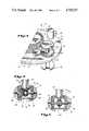
- FIG. 1is a perspective view of one embodiment of a drivable, steerable platform according to the present invention
- FIG. 2is a perspective view of a wheel assembly employed in the platform depicted in FIGS. 1 and 3, and of a top shaft assembly employed in the embodiment depicted in FIG. 3;
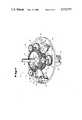
- FIG. 3is a fragmentary perspective view of a drivable, steerable platform encapsulated within a spherical member
- FIG. 4is a fragmentary perspective view of a platform including an intermediate steering gear
- FIG. 5is a cross-sectional view of a wheel assembly including a differential gear arrangement
- FIG. 6is a cross-sectional view of a wheel assembly including a worm gear arrangement
- FIG. 7is an alternate embodiment of the platform illustrated in FIG. 1 but having an internal combustion engine instead of electric motors powered by electric batteries.
- a drivable, steerable platform 10having a frame member 12 generally disposed in a lateral plane.
- the platform 10includes a steering shaft 14.
- One end of steering shaft 14is rotatably attached to and extends normally from the frame member 12.
- the steering shaftis free to rotate endlessly relative to the frame member 12.
- a steering gear 16is rigidly attached to the steering shaft 14.
- the steering gear 16has control teeth 18 and drive teeth 20.
- the control teeth 18are circumferentially disposed, rigidly attached to and extend radially outwardly from the steering gear 16.
- the control teeth 18lie generally in the same plane as the steering gear 16.
- the drive teeth 20are circumferentially disposed, rigidly attached to and extend normally from the side of steering gear 16.
- a drive pipe shaft 22is concentrically and rotatably mounted around the steering shaft 14.
- the drive pipe shaft 22is free to rotate endlessly relative to the steering shaft 14.
- a drive gear 24is rigidly attached to the drive pipe shaft 22.
- the drive gear 24has control teeth 26 and drive teeth 28.
- the control teeth 26are circumferentially disposed, rigidly attached to and extend radially outwardly from the drive gear 24.
- the control teeth 26lie generally in the same plane as the drive gear 24.
- the drive teeth 28are circumferentially disposed, rigidly attached to, and extend normally from the drive gear 24--i.e., perpendicular to the side of drive gear 24.
- a steering motor 30 with a power source 32is provided to drive the steering gear 16.
- the steering motor 30is rigidly attached to the frame member 12 by a motor support member 34.
- the steering motor 30includes a shaft 36 and a drive gear 38.
- the steering motor drive gear 38is rigidly attached to the steering motor shaft 36.
- the steering motor drive gear 38meshes with the steering gear drive teeth 20.
- the steering motor 30is actuated by a platform steering control means not shown.
- a drive motor 40is provided with a power source 42 to drive the drive gear 24.
- the drive motoris rigidly attached to the platform frame member 12 by a motor support member 44.
- the drive motor 40includes a shaft 46 and a drive gear 48.
- the drive motor drive gear 48is fixedly attached to the drive motor shaft 46.
- the drive motor drive gear 48meshes with the drive gear drive teeth 28.
- the drive motor 40is actuated by a platform driving control means not shown.
- the platform 10further includes three identical wheel assemblies 50.
- Each wheel assembly 50includes a hollow, pipe-like, steering control shaft 52 which is rotatably attached to and extends normally downward from the platform member 12.
- the steering control shaft 52is free to rotate endlessly relative to the platform member 12.
- a steering control gear 54is rigidly attached to the steering control shaft 52.
- the steering control gear 54meshes with the steering gear control teeth 18 and is directly driven by the steering gear 16.
- a wheel axle 56is rotatably attached to the lower end of steering control shaft 52--i.e., at the end opposite the steering control gear 54.
- the axis of the wheel axle 56lies in a plane generally perpendicular to the steering control shaft 52 and generally parallel to the frame member 12.
- the wheel axle 56includes a wheel axle gear 66 which is conveniently a bevel gear. Rigidly attached to each end of each wheel axle 56 are wheels 58.
- the wheel assembly 50further includes a drive control shaft 60.
- the drive control shaft 60is concentrically and rotatably mounted within the steering control shaft 52.
- the drive control shaft 60is free to rotate endlessly within the steering control shaft 52.
- a drive control gear 62is fixedly attached to the upper end of drive control shaft 60.
- the drive control gear 62meshes with the drive gear control teeth 26 and is directly driven by the drive gear 24.
- the drive control shaft 60extends normally downward inside the steering control sahft 52 in order to couple with the wheel axle gear 66.
- the coupling end of the drive control shaft 60includes a drive control shaft drive gear 64.
- the drive gear 64meshes with the wheel axle gear 66 to directly drive the wheel axle 56.
- FIG. 5Illustrated in FIG. 5 is a platform wheel assembly 50 comprising a differential gear arrangement 81. It will be apparent to one skilled in the art that the differential gear arrangement 81 will minimize friction on the wheels 58, and reduce the angular slip of the platform 10.
- the differential gear arrangement 81comprises a drive control shaft drive gear 64, a wheel axle having two half shafts 82 and 84, a differential housing 86, a ring gear 88, two half shaft pinion gears 90 and 92 and two differential gears 94 and 96.
- the wheel axlecomprises the two half shafts 82 and 84. Rigidly attached to the free end of both half shafts 82 and 84 are the half shaft pinion gears 90 and 92. The half shaft pinion gears 90 and 92 are enclosed within the differential housing 86. The differential housing 86 is rotatably attached to the half shafts 80 and 84. The gears 94 and 96 are of course free-running, as will be apparent to those skilled in the art.
- differential gear arrangementscan be used.
- arrangements other than differential gear arrangementscan be used without departing from the spirit of the present invention.
- Two such alternate arrangementsinclude the use of worm gears 66a, 64a (FIG. 6) and of bevel gears 66, 64 (FIG. 2).
- the use of a differentialis preferred for the resulting higher accuracy, lower friction and greater traction.
- the alternate embodiment in which worm gears are used with each wheel assemblypermits reduced speed and increased torque.
- the platform speed and directionmay be determined by a platform control means not shown.
- Control means availableinclude but are not limited to manual, remote, cassette or computer program controls. Such control means are claimed and more specifically described in the original application Ser. No. 353,250, filed Mar. 1, 1982 and now U.S. Pat. No. 4,463,821, and in continuation application Ser. No. 628,337, filed July 6, 1984 and now U.S. Pat. No. 4,533,998, both of which are hereby incorporated by reference.
- the control means of the preferred embodimentactuates the steering motor 30 and the drive motor 40 independently from each other.
- the steering gear 16simultaneously and uniformly turns each of the steering control gears 54.
- the angular rotation of each steering control gear 54is directly imparted to steer the wheel axle 56 through the steering control shaft 52.
- the direction of the platform's travelis determined by the movement of the steering control shaft 52.
- the platformtravels in straight line segments, with movement of the steering control shaft 52 marking the beginning and the end of a particular straight line segment.
- travel along a curved pathis approximated by travel along straight line segments that are essentially chords to the curve, the smaller the length of the chords the better the approximation to the curve.
- actuation of the steering motor by the control meansprovides a means of determining and controlling the direction of the platform.
- the drive motor 40When actuated by the control means the drive motor 40 directly drives the drive gear 24.
- the drive gear 24simultaneously and uniformly turns each of the drive control gears 62.
- the angular rotation of the drive control gear 62is directly imparted on to the drive control shaft 60.
- the drive control shaft drive gear 64then couples with the wheel axle gear 66 and radially rotates the wheel axle 56.
- actuation of the drive motor by the control meansprovides a means of determining and controlling the platform's speed of travel.
- a tray, robot arm, end effector, suction device, shelf, carriage member and so forthmay be attached, for example, to the frame member 12 or to rotate in synchronism with the main steering shaft--i.e., shaft 14 in FIG. 1.
- a direction finder or indicator 15may be added to the platform to indicate, or to acquire and generate information needed to control, the direction in which the platform will travel.
- Such an indicatormay be mounted or suitably coupled to the steering shaft 14, steering gear 16, steering control shaft 52 or the steering control gear 54 so that it rotates in synchronism with the steering shaft 14.
- the steering gear 16 and steering control gear 54must be appropriately dimensioned so that each of the gears 16 and 54 simultaneously undergo the same angular translation.
- FIG. 4shows the intermediate steering gear 25.
- the gear 25is rotatably attached to the frame member 12 by an intermediate gear shaft (not shown).
- the intermediate gear 25meshed with and is driven by the steering gear 16 and simultaneously meshes with a steering control gear 54. It will be apparent to one skilled in the art that this arrangement allows the steering shaft 14 and the steering control gear 54 to turn in the same direction.
- the platform 10may be used in conjunction with a variety of implements attached to the platform.
- Implements availableinclude but are not limited to omnidirectional vacuum cleaners, suction devices for omnidirectional vacuum cleaning, end effectors, metal detectors, script writers, spray painters, and torches, as well as trays, carriages, robotic arms, direction finders or indicators and so forth.
- a metal detecting implement 17may be attached to the platform 10. (FIG. 1) This arrangement provides a means of finding metal coins, artifacts, pipelines, power lines or other metallic objects.
- FIG. 4.Another example includes having a paint sprayer 19 attached to the platform 10.
- this platform/paint sprayermay be used to paint walls, floors and ceilings of structures, parts used in assembly lines, lines on roadway, or any other painting function.
- a script writermay be attached to the platform.
- the platform/script writer arrangementmay be used to: draw graphics; make signs; design drawing and perform other like scriptive functions.
- the implementmay be attached anywhere on the platform and have the same relative direction and speed of travel as the center of the platform 10, or as previously indicated, can be advantageously mounted to rotate in synchronism with the steering shaft 14.
- FIG. 3depicts a platform 10 encapsulated in a spherical member 70.
- Each of the platform wheels 58is in contact with the inner surface 72 of the spherical member 70.
- the platform 10 of this embodimentfurther includes a spring-drive piston 74 mounted within the steering shaft 14, as best illustrated in FIG. 2.
- the steering shaftis concentrically bored out to provide a means to mount the piston 74.
- a spring 76is attached to the bottom of the bored-out section of the steering shaft 14.
- the top end of the spring 76is attached to the piston 74 which seats in the bored-out section of the steering shaft 14.
- a ball 80is rotatably attached to the top end of the piston 74. In FIG. 3, the ball 80 contacts the top of the inner surface 72 of the spherical member 70. It will be apparent to those skilled in the art that the piston 74 could alternatively be mounted anywhere on the platform 10.
- the ball 80 at end of the piston 74 and the platform wheels 58are the platform's only contact points to the inner surface 72 of the spherical member 70.
- This gimbal-type arrangementserves several functions. One function of the arrangement is to stabilize the platform 10 within the spherical member 70. An additional and equally important function is to provide contact pressure between the wheels 58 and the spherical member's inner surface 72. The contact pressure allows the wheels 58 to translate their motion to the spherical member 70. The motion translated from the platform's wheels 58 causes the spherical member 70 to roll and provides the means for controlling the direction and speed of the rolling spherical member 70.
- the center of gravity of the platform 10located beneath the center of gravity of the spherical member 70.
- a plurality of protrusions or depressionsmay be included on the outer surface 78 of the spherical member 70 to improve traction of the rolling spherical member 70 over solid and semi-solid surfaces. Such protrusions, depressions or other traction improving structure is generally needed for the rolling sphere to climb stairs. Furthermore, a plurality of fins (not shown) may be included on the outer surface 78 to aid in directing and driving the rolling spherical member 70 through water.
Landscapes
- Engineering & Computer Science (AREA)
- Chemical & Material Sciences (AREA)
- Combustion & Propulsion (AREA)
- Transportation (AREA)
- Mechanical Engineering (AREA)
- Toys (AREA)
Abstract
Description
Claims (10)
Priority Applications (1)
| Application Number | Priority Date | Filing Date | Title |
|---|---|---|---|
| US06/770,729US4733737A (en) | 1985-08-29 | 1985-08-29 | Drivable steerable platform for industrial, domestic, entertainment and like uses |
Applications Claiming Priority (1)
| Application Number | Priority Date | Filing Date | Title |
|---|---|---|---|
| US06/770,729US4733737A (en) | 1985-08-29 | 1985-08-29 | Drivable steerable platform for industrial, domestic, entertainment and like uses |
Publications (1)
| Publication Number | Publication Date |
|---|---|
| US4733737Atrue US4733737A (en) | 1988-03-29 |
Family
ID=25089502
Family Applications (1)
| Application Number | Title | Priority Date | Filing Date |
|---|---|---|---|
| US06/770,729Expired - LifetimeUS4733737A (en) | 1985-08-29 | 1985-08-29 | Drivable steerable platform for industrial, domestic, entertainment and like uses |
Country Status (1)
| Country | Link |
|---|---|
| US (1) | US4733737A (en) |
Cited By (90)
| Publication number | Priority date | Publication date | Assignee | Title |
|---|---|---|---|---|
| US5374879A (en)* | 1992-11-04 | 1994-12-20 | Martin Marietta Energy Systems, Inc. | Omni-directional and holonomic rolling platform with decoupled rotational and translational degrees of freedom |
| US5467275A (en)* | 1992-03-19 | 1995-11-14 | Hitachi, Ltd. | Control apparatus for electric vehicle |
| WO1997025239A1 (en)* | 1996-01-09 | 1997-07-17 | Teknillinen Korkeakoulu | Ball robot and method for determining position thereof |
| US5807202A (en)* | 1996-09-04 | 1998-09-15 | Sikorsky Aircraft Corporation | Differential speed transmission |
| US5851162A (en)* | 1996-11-19 | 1998-12-22 | Tether; David | System and apparatus for a multiple input and dual output electric differential motor transmission device |
| US6028384A (en)* | 1998-11-17 | 2000-02-22 | Cei | Actuator |
| US6474434B1 (en)* | 1997-07-02 | 2002-11-05 | Borringis Industrie Ag | Drive wheel |
| US20030102724A1 (en)* | 2001-11-02 | 2003-06-05 | Roy Shambhu N. | Single motor, multi-axis stage |
| US20030126701A1 (en)* | 2000-10-30 | 2003-07-10 | Turbjorn Aasen | Mobile robot |
| US20040143421A1 (en)* | 2002-07-25 | 2004-07-22 | Yulun Wang | Apparatus and method for patient rounding with a remote controlled robot |
| US20040232683A1 (en)* | 2003-05-23 | 2004-11-25 | Mulhern James P. | Anti-tip wheel for a wheelchair |
| WO2004109158A1 (en)* | 2003-06-09 | 2004-12-16 | Hanool Robotics Corp | Decoupled synchro-drive mobile robot base |
| US20050001576A1 (en)* | 2003-07-02 | 2005-01-06 | Laby Keith Phillip | Holonomic platform for a robot |
| US20050061560A1 (en)* | 2002-01-22 | 2005-03-24 | Visual Act Scandinvia Ab | Drive unit, and a powered vehicle |
| US20050125098A1 (en)* | 2003-12-09 | 2005-06-09 | Yulun Wang | Protocol for a remotely controlled videoconferencing robot |
| US20050204438A1 (en)* | 2004-02-26 | 2005-09-15 | Yulun Wang | Graphical interface for a remote presence system |
| US20060052676A1 (en)* | 2004-09-07 | 2006-03-09 | Yulun Wang | Tele-presence system that allows for remote monitoring/observation and review of a patient and their medical records |
| US20060082642A1 (en)* | 2002-07-25 | 2006-04-20 | Yulun Wang | Tele-robotic videoconferencing in a corporate environment |
| US20060161303A1 (en)* | 2005-01-18 | 2006-07-20 | Yulun Wang | Mobile videoconferencing platform with automatic shut-off features |
| US20060197299A1 (en)* | 2005-03-07 | 2006-09-07 | Stryker Martin W | Convertible low profile roller and support base |
| US20060259193A1 (en)* | 2005-05-12 | 2006-11-16 | Yulun Wang | Telerobotic system with a dual application screen presentation |
| US20070078566A1 (en)* | 2005-09-30 | 2007-04-05 | Yulun Wang | Multi-camera mobile teleconferencing platform |
| US20070124859A1 (en)* | 2005-12-01 | 2007-06-07 | Stryker Martin W | Single step wheelchair transfer device |
| US20070152427A1 (en)* | 2005-12-30 | 2007-07-05 | Olsen Christopher J | Articulated wheel assemblies and vehicles therewith |
| US20070198130A1 (en)* | 2006-02-22 | 2007-08-23 | Yulun Wang | Graphical interface for a remote presence system |
| US7262573B2 (en) | 2003-03-06 | 2007-08-28 | Intouch Technologies, Inc. | Medical tele-robotic system with a head worn device |
| US20070291109A1 (en)* | 2006-06-15 | 2007-12-20 | Yulun Wang | Remote controlled mobile robot with auxillary input ports |
| US20080065268A1 (en)* | 2002-07-25 | 2008-03-13 | Yulun Wang | Medical Tele-robotic system with a master remote station with an arbitrator |
| US20080082211A1 (en)* | 2006-10-03 | 2008-04-03 | Yulun Wang | Remote presence display through remotely controlled robot |
| US20080197694A1 (en)* | 2003-10-02 | 2008-08-21 | Blevio Henry L | Ball wheel for an aircraft |
| US20080281467A1 (en)* | 2007-05-09 | 2008-11-13 | Marco Pinter | Robot system that operates through a network firewall |
| US20090055023A1 (en)* | 2007-08-23 | 2009-02-26 | Derek Walters | Telepresence robot with a printer |
| US20090240371A1 (en)* | 2008-03-20 | 2009-09-24 | Yulun Wang | Remote presence system mounted to operating room hardware |
| US20100010672A1 (en)* | 2008-07-10 | 2010-01-14 | Yulun Wang | Docking system for a tele-presence robot |
| US20100131103A1 (en)* | 2008-11-25 | 2010-05-27 | Intouch Technologies, Inc. | Server connectivity control for tele-presence robot |
| US20100125968A1 (en)* | 2008-11-26 | 2010-05-27 | Howard Ho | Automated apparatus and equipped trashcan |
| WO2010083473A1 (en) | 2009-01-17 | 2010-07-22 | Boomerang Systems, Inc. | Omnidirectional drive and steering unit |
| US20100191375A1 (en)* | 2009-01-29 | 2010-07-29 | Wright Timothy C | Documentation through a remote presence robot |
| US20110024558A1 (en)* | 2003-10-02 | 2011-02-03 | Blevio Sr Henry L | Ball wheel for an aircraft |
| US20110168474A1 (en)* | 2010-01-14 | 2011-07-14 | Boomerang Systems, Inc. | Slewing ring drive |
| US20110187875A1 (en)* | 2010-02-04 | 2011-08-04 | Intouch Technologies, Inc. | Robot face used in a sterile environment |
| US20110190930A1 (en)* | 2010-02-04 | 2011-08-04 | Intouch Technologies, Inc. | Robot user interface for telepresence robot system |
| US20110213210A1 (en)* | 2009-08-26 | 2011-09-01 | Intouch Technologies, Inc. | Portable telepresence apparatus |
| US20110218674A1 (en)* | 2010-03-04 | 2011-09-08 | David Stuart | Remote presence system including a cart that supports a robot face and an overhead camera |
| US8077963B2 (en) | 2004-07-13 | 2011-12-13 | Yulun Wang | Mobile robot with a head-based movement mapping scheme |
| US20120006609A1 (en)* | 2009-12-29 | 2012-01-12 | Fori Automation, Inc. | Drive mechanism for automated guided vehicle |
| US8340819B2 (en) | 2008-09-18 | 2012-12-25 | Intouch Technologies, Inc. | Mobile videoconferencing robot system with network adaptive driving |
| US20140238762A1 (en)* | 2011-01-05 | 2014-08-28 | Orbotix, Inc. | Multi-purposed self-propelled device |
| US8836751B2 (en) | 2011-11-08 | 2014-09-16 | Intouch Technologies, Inc. | Tele-presence system with a user interface that displays different communication links |
| US8861750B2 (en) | 2008-04-17 | 2014-10-14 | Intouch Technologies, Inc. | Mobile tele-presence system with a microphone system |
| CN104129430A (en)* | 2014-08-14 | 2014-11-05 | 柳州君天机器人自动化有限公司 | Full steering moving chassis |
| US8897920B2 (en) | 2009-04-17 | 2014-11-25 | Intouch Technologies, Inc. | Tele-presence robot system with software modularity, projector and laser pointer |
| US8902278B2 (en) | 2012-04-11 | 2014-12-02 | Intouch Technologies, Inc. | Systems and methods for visualizing and managing telepresence devices in healthcare networks |
| CN104228993A (en)* | 2014-10-17 | 2014-12-24 | 浙江大学 | Biped robot capable of walking rapidly |
| US8965579B2 (en) | 2011-01-28 | 2015-02-24 | Intouch Technologies | Interfacing with a mobile telepresence robot |
| US8996165B2 (en) | 2008-10-21 | 2015-03-31 | Intouch Technologies, Inc. | Telepresence robot with a camera boom |
| US9098611B2 (en) | 2012-11-26 | 2015-08-04 | Intouch Technologies, Inc. | Enhanced video interaction for a user interface of a telepresence network |
| US9138891B2 (en) | 2008-11-25 | 2015-09-22 | Intouch Technologies, Inc. | Server connectivity control for tele-presence robot |
| US9174342B2 (en) | 2012-05-22 | 2015-11-03 | Intouch Technologies, Inc. | Social behavior rules for a medical telepresence robot |
| US9193404B2 (en) | 2011-01-05 | 2015-11-24 | Sphero, Inc. | Self-propelled device with actively engaged drive system |
| US9251313B2 (en) | 2012-04-11 | 2016-02-02 | Intouch Technologies, Inc. | Systems and methods for visualizing and managing telepresence devices in healthcare networks |
| US9264664B2 (en) | 2010-12-03 | 2016-02-16 | Intouch Technologies, Inc. | Systems and methods for dynamic bandwidth allocation |
| US9323250B2 (en) | 2011-01-28 | 2016-04-26 | Intouch Technologies, Inc. | Time-dependent navigation of telepresence robots |
| US9361021B2 (en) | 2012-05-22 | 2016-06-07 | Irobot Corporation | Graphical user interfaces including touchpad driving interfaces for telemedicine devices |
| US20160280524A1 (en)* | 2015-03-25 | 2016-09-29 | Columbia Trailer Co., Inc. | Method and apparatus for transporting and steering a heavy load |
| US9573416B1 (en)* | 2015-10-23 | 2017-02-21 | Disney Enterprises, Inc. | Wheel assembly with multi-sphere omniwheels and omnidirectional devices including the wheel assembly |
| US9602765B2 (en) | 2009-08-26 | 2017-03-21 | Intouch Technologies, Inc. | Portable remote presence robot |
| US9829882B2 (en) | 2013-12-20 | 2017-11-28 | Sphero, Inc. | Self-propelled device with center of mass drive system |
| US9827487B2 (en) | 2012-05-14 | 2017-11-28 | Sphero, Inc. | Interactive augmented reality using a self-propelled device |
| US9842192B2 (en) | 2008-07-11 | 2017-12-12 | Intouch Technologies, Inc. | Tele-presence robot system with multi-cast features |
| CN107600149A (en)* | 2017-10-21 | 2018-01-19 | 广东九御酒业有限公司 | A kind of wheel with turning function and speed-regulating function |
| US9886032B2 (en) | 2011-01-05 | 2018-02-06 | Sphero, Inc. | Self propelled device with magnetic coupling |
| US9974612B2 (en) | 2011-05-19 | 2018-05-22 | Intouch Technologies, Inc. | Enhanced diagnostics for a telepresence robot |
| US10022643B2 (en) | 2011-01-05 | 2018-07-17 | Sphero, Inc. | Magnetically coupled accessory for a self-propelled device |
| US10056791B2 (en) | 2012-07-13 | 2018-08-21 | Sphero, Inc. | Self-optimizing power transfer |
| US10192310B2 (en) | 2012-05-14 | 2019-01-29 | Sphero, Inc. | Operating a computing device by detecting rounded objects in an image |
| CN109383664A (en)* | 2018-12-19 | 2019-02-26 | 湖北三江航天万山特种车辆有限公司 | A kind of heavy electric drive steering wheel of differential steering |
| US10343283B2 (en) | 2010-05-24 | 2019-07-09 | Intouch Technologies, Inc. | Telepresence robot system that can be accessed by a cellular phone |
| US10471588B2 (en) | 2008-04-14 | 2019-11-12 | Intouch Technologies, Inc. | Robotic based health care system |
| US10769739B2 (en) | 2011-04-25 | 2020-09-08 | Intouch Technologies, Inc. | Systems and methods for management of information among medical providers and facilities |
| US10808882B2 (en) | 2010-05-26 | 2020-10-20 | Intouch Technologies, Inc. | Tele-robotic system with a robot face placed on a chair |
| US11294378B2 (en) | 2018-03-29 | 2022-04-05 | Disney Enterprises, Inc. | Park attraction with collaborative passenger control of holonomic vehicles |
| US11389064B2 (en) | 2018-04-27 | 2022-07-19 | Teladoc Health, Inc. | Telehealth cart that supports a removable tablet with seamless audio/video switching |
| US11636944B2 (en) | 2017-08-25 | 2023-04-25 | Teladoc Health, Inc. | Connectivity infrastructure for a telehealth platform |
| US11661126B2 (en) | 2018-08-17 | 2023-05-30 | Columbia Trailer Co., Inc. | Method and apparatus for transporting and steering a heavy load |
| US11742094B2 (en) | 2017-07-25 | 2023-08-29 | Teladoc Health, Inc. | Modular telehealth cart with thermal imaging and touch screen user interface |
| US20230373559A1 (en)* | 2022-03-29 | 2023-11-23 | Beihang University | Steering wheel structure for an omnidirectional mobile robot chassis |
| US11862302B2 (en) | 2017-04-24 | 2024-01-02 | Teladoc Health, Inc. | Automated transcription and documentation of tele-health encounters |
| US12093036B2 (en) | 2011-01-21 | 2024-09-17 | Teladoc Health, Inc. | Telerobotic system with a dual application screen presentation |
| US12224059B2 (en) | 2011-02-16 | 2025-02-11 | Teladoc Health, Inc. | Systems and methods for network-based counseling |
Citations (7)
| Publication number | Priority date | Publication date | Assignee | Title |
|---|---|---|---|---|
| BE512471A (en)* | ||||
| US1026122A (en)* | 1909-09-07 | 1912-05-14 | Joseph L Prather | Steering-wheel. |
| US1266904A (en)* | 1918-05-21 | baker | ||
| US3232005A (en)* | 1962-01-19 | 1966-02-01 | Robert G Lahr | Vehicle driving and steering device |
| US4463821A (en)* | 1982-03-01 | 1984-08-07 | Robot Crabtor International | Drivable, steerable platform for lawnmower and the like |
| US4519466A (en)* | 1982-03-30 | 1985-05-28 | Eiko Shiraishi | Omnidirectional drive system |
| US4533998A (en)* | 1982-03-01 | 1985-08-06 | Reza Falamak | Control apparatus for omnidirectional, polar coordinated platform for lawnmower and the like |
- 1985
- 1985-08-29USUS06/770,729patent/US4733737A/ennot_activeExpired - Lifetime
Patent Citations (7)
| Publication number | Priority date | Publication date | Assignee | Title |
|---|---|---|---|---|
| BE512471A (en)* | ||||
| US1266904A (en)* | 1918-05-21 | baker | ||
| US1026122A (en)* | 1909-09-07 | 1912-05-14 | Joseph L Prather | Steering-wheel. |
| US3232005A (en)* | 1962-01-19 | 1966-02-01 | Robert G Lahr | Vehicle driving and steering device |
| US4463821A (en)* | 1982-03-01 | 1984-08-07 | Robot Crabtor International | Drivable, steerable platform for lawnmower and the like |
| US4533998A (en)* | 1982-03-01 | 1985-08-06 | Reza Falamak | Control apparatus for omnidirectional, polar coordinated platform for lawnmower and the like |
| US4519466A (en)* | 1982-03-30 | 1985-05-28 | Eiko Shiraishi | Omnidirectional drive system |
Cited By (208)
| Publication number | Priority date | Publication date | Assignee | Title |
|---|---|---|---|---|
| US5467275A (en)* | 1992-03-19 | 1995-11-14 | Hitachi, Ltd. | Control apparatus for electric vehicle |
| US5374879A (en)* | 1992-11-04 | 1994-12-20 | Martin Marietta Energy Systems, Inc. | Omni-directional and holonomic rolling platform with decoupled rotational and translational degrees of freedom |
| WO1997025239A1 (en)* | 1996-01-09 | 1997-07-17 | Teknillinen Korkeakoulu | Ball robot and method for determining position thereof |
| US5807202A (en)* | 1996-09-04 | 1998-09-15 | Sikorsky Aircraft Corporation | Differential speed transmission |
| US5851162A (en)* | 1996-11-19 | 1998-12-22 | Tether; David | System and apparatus for a multiple input and dual output electric differential motor transmission device |
| US6474434B1 (en)* | 1997-07-02 | 2002-11-05 | Borringis Industrie Ag | Drive wheel |
| US6028384A (en)* | 1998-11-17 | 2000-02-22 | Cei | Actuator |
| US20030126701A1 (en)* | 2000-10-30 | 2003-07-10 | Turbjorn Aasen | Mobile robot |
| US6938298B2 (en)* | 2000-10-30 | 2005-09-06 | Turbjorn Aasen | Mobile cleaning robot for floors |
| US20030102724A1 (en)* | 2001-11-02 | 2003-06-05 | Roy Shambhu N. | Single motor, multi-axis stage |
| US6740998B2 (en)* | 2001-11-02 | 2004-05-25 | Advantest Corporation | Single motor, multi-axis stage |
| US20050061560A1 (en)* | 2002-01-22 | 2005-03-24 | Visual Act Scandinvia Ab | Drive unit, and a powered vehicle |
| US7296643B2 (en)* | 2002-01-22 | 2007-11-20 | Visual Act Scandinavia Ab | Drive unit, and a powered vehicle |
| US20080065268A1 (en)* | 2002-07-25 | 2008-03-13 | Yulun Wang | Medical Tele-robotic system with a master remote station with an arbitrator |
| US7310570B2 (en) | 2002-07-25 | 2007-12-18 | Yulun Wang | Medical tele-robotic system |
| US20050021182A1 (en)* | 2002-07-25 | 2005-01-27 | Yulun Wang | Medical tele-robotic system |
| US20050021187A1 (en)* | 2002-07-25 | 2005-01-27 | Yulun Wang | Medical tele-robotic system |
| US8209051B2 (en) | 2002-07-25 | 2012-06-26 | Intouch Technologies, Inc. | Medical tele-robotic system |
| US20050027400A1 (en)* | 2002-07-25 | 2005-02-03 | Yulun Wang | Medical tele-robotic system |
| US20050021183A1 (en)* | 2002-07-25 | 2005-01-27 | Yulun Wang | Medical tele-robotic system |
| US20080255703A1 (en)* | 2002-07-25 | 2008-10-16 | Yulun Wang | Medical tele-robotic system |
| US7593030B2 (en) | 2002-07-25 | 2009-09-22 | Intouch Technologies, Inc. | Tele-robotic videoconferencing in a corporate environment |
| US20080029536A1 (en)* | 2002-07-25 | 2008-02-07 | Intouch Technologies, Inc. | Medical tele-robotic system |
| US8515577B2 (en) | 2002-07-25 | 2013-08-20 | Yulun Wang | Medical tele-robotic system with a master remote station with an arbitrator |
| US20050240310A1 (en)* | 2002-07-25 | 2005-10-27 | Yulun Wang | Medical tele-robotic system |
| US20090105882A1 (en)* | 2002-07-25 | 2009-04-23 | Intouch Technologies, Inc. | Medical Tele-Robotic System |
| US20060082642A1 (en)* | 2002-07-25 | 2006-04-20 | Yulun Wang | Tele-robotic videoconferencing in a corporate environment |
| US7289883B2 (en) | 2002-07-25 | 2007-10-30 | Intouch Technologies, Inc. | Apparatus and method for patient rounding with a remote controlled robot |
| US9849593B2 (en) | 2002-07-25 | 2017-12-26 | Intouch Technologies, Inc. | Medical tele-robotic system with a master remote station with an arbitrator |
| US20040143421A1 (en)* | 2002-07-25 | 2004-07-22 | Yulun Wang | Apparatus and method for patient rounding with a remote controlled robot |
| US7142945B2 (en) | 2002-07-25 | 2006-11-28 | Intouch Technologies, Inc. | Medical tele-robotic system |
| US7142947B2 (en) | 2002-07-25 | 2006-11-28 | Intouch Technologies, Inc. | Medical tele-robotic method |
| US7158861B2 (en) | 2002-07-25 | 2007-01-02 | Intouch Technologies, Inc. | Tele-robotic system used to provide remote consultation services |
| US7164970B2 (en) | 2002-07-25 | 2007-01-16 | Intouch Technologies, Inc. | Medical tele-robotic system |
| US7164969B2 (en) | 2002-07-25 | 2007-01-16 | Intouch Technologies, Inc. | Apparatus and method for patient rounding with a remote controlled robot |
| US20070021871A1 (en)* | 2002-07-25 | 2007-01-25 | Yulun Wang | Medical tele-robotic system |
| USRE45870E1 (en) | 2002-07-25 | 2016-01-26 | Intouch Technologies, Inc. | Apparatus and method for patient rounding with a remote controlled robot |
| US10315312B2 (en) | 2002-07-25 | 2019-06-11 | Intouch Technologies, Inc. | Medical tele-robotic system with a master remote station with an arbitrator |
| US7218992B2 (en) | 2002-07-25 | 2007-05-15 | Intouch Technologies, Inc. | Medical tele-robotic system |
| US20070112464A1 (en)* | 2002-07-25 | 2007-05-17 | Yulun Wang | Apparatus and method for patient rounding with a remote controlled robot |
| US7262573B2 (en) | 2003-03-06 | 2007-08-28 | Intouch Technologies, Inc. | Medical tele-robotic system with a head worn device |
| EP1479362A3 (en)* | 2003-05-23 | 2005-02-02 | Pride Mobility Products, Corporation | Anti-tip wheel for a wheelchair |
| US7311329B2 (en) | 2003-05-23 | 2007-12-25 | Pride Mobility Products Corporation | Anti-tip wheel for a wheelchair |
| US20040232683A1 (en)* | 2003-05-23 | 2004-11-25 | Mulhern James P. | Anti-tip wheel for a wheelchair |
| US7634327B2 (en) | 2003-06-09 | 2009-12-15 | Hanool Robotics Corp | Decoupled synchro-drive robot base |
| US20070100497A1 (en)* | 2003-06-09 | 2007-05-03 | Ui-Jung Jung | Decoupled synchro-drive mobile robot base |
| WO2004109158A1 (en)* | 2003-06-09 | 2004-12-16 | Hanool Robotics Corp | Decoupled synchro-drive mobile robot base |
| US20050001576A1 (en)* | 2003-07-02 | 2005-01-06 | Laby Keith Phillip | Holonomic platform for a robot |
| US6888333B2 (en)* | 2003-07-02 | 2005-05-03 | Intouch Health, Inc. | Holonomic platform for a robot |
| US20080197694A1 (en)* | 2003-10-02 | 2008-08-21 | Blevio Henry L | Ball wheel for an aircraft |
| US8286737B2 (en)* | 2003-10-02 | 2012-10-16 | Blevio Sr Henry L | Ball wheel for an aircraft |
| US20110024558A1 (en)* | 2003-10-02 | 2011-02-03 | Blevio Sr Henry L | Ball wheel for an aircraft |
| US20050125098A1 (en)* | 2003-12-09 | 2005-06-09 | Yulun Wang | Protocol for a remotely controlled videoconferencing robot |
| US9956690B2 (en) | 2003-12-09 | 2018-05-01 | Intouch Technologies, Inc. | Protocol for a remotely controlled videoconferencing robot |
| US7813836B2 (en) | 2003-12-09 | 2010-10-12 | Intouch Technologies, Inc. | Protocol for a remotely controlled videoconferencing robot |
| US10882190B2 (en) | 2003-12-09 | 2021-01-05 | Teladoc Health, Inc. | Protocol for a remotely controlled videoconferencing robot |
| US20100115418A1 (en)* | 2004-02-26 | 2010-05-06 | Yulun Wang | Graphical interface for a remote presence system |
| US20050204438A1 (en)* | 2004-02-26 | 2005-09-15 | Yulun Wang | Graphical interface for a remote presence system |
| US9610685B2 (en) | 2004-02-26 | 2017-04-04 | Intouch Technologies, Inc. | Graphical interface for a remote presence system |
| US8983174B2 (en) | 2004-07-13 | 2015-03-17 | Intouch Technologies, Inc. | Mobile robot with a head-based movement mapping scheme |
| US10241507B2 (en) | 2004-07-13 | 2019-03-26 | Intouch Technologies, Inc. | Mobile robot with a head-based movement mapping scheme |
| US8077963B2 (en) | 2004-07-13 | 2011-12-13 | Yulun Wang | Mobile robot with a head-based movement mapping scheme |
| US8401275B2 (en) | 2004-07-13 | 2013-03-19 | Intouch Technologies, Inc. | Mobile robot with a head-based movement mapping scheme |
| US9766624B2 (en) | 2004-07-13 | 2017-09-19 | Intouch Technologies, Inc. | Mobile robot with a head-based movement mapping scheme |
| US20060052676A1 (en)* | 2004-09-07 | 2006-03-09 | Yulun Wang | Tele-presence system that allows for remote monitoring/observation and review of a patient and their medical records |
| US7222000B2 (en) | 2005-01-18 | 2007-05-22 | Intouch Technologies, Inc. | Mobile videoconferencing platform with automatic shut-off features |
| US20060161303A1 (en)* | 2005-01-18 | 2006-07-20 | Yulun Wang | Mobile videoconferencing platform with automatic shut-off features |
| US7441786B2 (en)* | 2005-03-07 | 2008-10-28 | Stryker Corporation | Convertible low profile roller and support base |
| US20060197299A1 (en)* | 2005-03-07 | 2006-09-07 | Stryker Martin W | Convertible low profile roller and support base |
| US20060259193A1 (en)* | 2005-05-12 | 2006-11-16 | Yulun Wang | Telerobotic system with a dual application screen presentation |
| US10259119B2 (en) | 2005-09-30 | 2019-04-16 | Intouch Technologies, Inc. | Multi-camera mobile teleconferencing platform |
| US20070078566A1 (en)* | 2005-09-30 | 2007-04-05 | Yulun Wang | Multi-camera mobile teleconferencing platform |
| US9198728B2 (en) | 2005-09-30 | 2015-12-01 | Intouch Technologies, Inc. | Multi-camera mobile teleconferencing platform |
| US7735165B2 (en) | 2005-12-01 | 2010-06-15 | Stryker Corporation | Single step wheelchair transfer device |
| US20070124859A1 (en)* | 2005-12-01 | 2007-06-07 | Stryker Martin W | Single step wheelchair transfer device |
| US20070152427A1 (en)* | 2005-12-30 | 2007-07-05 | Olsen Christopher J | Articulated wheel assemblies and vehicles therewith |
| US7426970B2 (en) | 2005-12-30 | 2008-09-23 | Olsen Christopher J | Articulated wheel assemblies and vehicles therewith |
| US7769492B2 (en) | 2006-02-22 | 2010-08-03 | Intouch Technologies, Inc. | Graphical interface for a remote presence system |
| US20070198130A1 (en)* | 2006-02-22 | 2007-08-23 | Yulun Wang | Graphical interface for a remote presence system |
| US20070291109A1 (en)* | 2006-06-15 | 2007-12-20 | Yulun Wang | Remote controlled mobile robot with auxillary input ports |
| US20080082211A1 (en)* | 2006-10-03 | 2008-04-03 | Yulun Wang | Remote presence display through remotely controlled robot |
| US7761185B2 (en) | 2006-10-03 | 2010-07-20 | Intouch Technologies, Inc. | Remote presence display through remotely controlled robot |
| US20080281467A1 (en)* | 2007-05-09 | 2008-11-13 | Marco Pinter | Robot system that operates through a network firewall |
| US9160783B2 (en) | 2007-05-09 | 2015-10-13 | Intouch Technologies, Inc. | Robot system that operates through a network firewall |
| US10682763B2 (en) | 2007-05-09 | 2020-06-16 | Intouch Technologies, Inc. | Robot system that operates through a network firewall |
| US8116910B2 (en) | 2007-08-23 | 2012-02-14 | Intouch Technologies, Inc. | Telepresence robot with a printer |
| US20090055023A1 (en)* | 2007-08-23 | 2009-02-26 | Derek Walters | Telepresence robot with a printer |
| US20090240371A1 (en)* | 2008-03-20 | 2009-09-24 | Yulun Wang | Remote presence system mounted to operating room hardware |
| US10875182B2 (en) | 2008-03-20 | 2020-12-29 | Teladoc Health, Inc. | Remote presence system mounted to operating room hardware |
| US11787060B2 (en) | 2008-03-20 | 2023-10-17 | Teladoc Health, Inc. | Remote presence system mounted to operating room hardware |
| US10471588B2 (en) | 2008-04-14 | 2019-11-12 | Intouch Technologies, Inc. | Robotic based health care system |
| US11472021B2 (en) | 2008-04-14 | 2022-10-18 | Teladoc Health, Inc. | Robotic based health care system |
| US8861750B2 (en) | 2008-04-17 | 2014-10-14 | Intouch Technologies, Inc. | Mobile tele-presence system with a microphone system |
| US10493631B2 (en) | 2008-07-10 | 2019-12-03 | Intouch Technologies, Inc. | Docking system for a tele-presence robot |
| US20100010672A1 (en)* | 2008-07-10 | 2010-01-14 | Yulun Wang | Docking system for a tele-presence robot |
| US9842192B2 (en) | 2008-07-11 | 2017-12-12 | Intouch Technologies, Inc. | Tele-presence robot system with multi-cast features |
| US10878960B2 (en) | 2008-07-11 | 2020-12-29 | Teladoc Health, Inc. | Tele-presence robot system with multi-cast features |
| US9429934B2 (en) | 2008-09-18 | 2016-08-30 | Intouch Technologies, Inc. | Mobile videoconferencing robot system with network adaptive driving |
| US8340819B2 (en) | 2008-09-18 | 2012-12-25 | Intouch Technologies, Inc. | Mobile videoconferencing robot system with network adaptive driving |
| US8996165B2 (en) | 2008-10-21 | 2015-03-31 | Intouch Technologies, Inc. | Telepresence robot with a camera boom |
| US9138891B2 (en) | 2008-11-25 | 2015-09-22 | Intouch Technologies, Inc. | Server connectivity control for tele-presence robot |
| US10059000B2 (en) | 2008-11-25 | 2018-08-28 | Intouch Technologies, Inc. | Server connectivity control for a tele-presence robot |
| US12138808B2 (en) | 2008-11-25 | 2024-11-12 | Teladoc Health, Inc. | Server connectivity control for tele-presence robots |
| US10875183B2 (en) | 2008-11-25 | 2020-12-29 | Teladoc Health, Inc. | Server connectivity control for tele-presence robot |
| US8463435B2 (en) | 2008-11-25 | 2013-06-11 | Intouch Technologies, Inc. | Server connectivity control for tele-presence robot |
| US20100131103A1 (en)* | 2008-11-25 | 2010-05-27 | Intouch Technologies, Inc. | Server connectivity control for tele-presence robot |
| US20100125968A1 (en)* | 2008-11-26 | 2010-05-27 | Howard Ho | Automated apparatus and equipped trashcan |
| EP2387526A4 (en)* | 2009-01-17 | 2017-10-18 | Boomerang Systems. Inc. | Omnidirectional drive and steering unit |
| WO2010083473A1 (en) | 2009-01-17 | 2010-07-22 | Boomerang Systems, Inc. | Omnidirectional drive and steering unit |
| US8849680B2 (en) | 2009-01-29 | 2014-09-30 | Intouch Technologies, Inc. | Documentation through a remote presence robot |
| US20100191375A1 (en)* | 2009-01-29 | 2010-07-29 | Wright Timothy C | Documentation through a remote presence robot |
| US10969766B2 (en) | 2009-04-17 | 2021-04-06 | Teladoc Health, Inc. | Tele-presence robot system with software modularity, projector and laser pointer |
| US8897920B2 (en) | 2009-04-17 | 2014-11-25 | Intouch Technologies, Inc. | Tele-presence robot system with software modularity, projector and laser pointer |
| US10404939B2 (en) | 2009-08-26 | 2019-09-03 | Intouch Technologies, Inc. | Portable remote presence robot |
| US11399153B2 (en) | 2009-08-26 | 2022-07-26 | Teladoc Health, Inc. | Portable telepresence apparatus |
| US10911715B2 (en) | 2009-08-26 | 2021-02-02 | Teladoc Health, Inc. | Portable remote presence robot |
| US9602765B2 (en) | 2009-08-26 | 2017-03-21 | Intouch Technologies, Inc. | Portable remote presence robot |
| US20110213210A1 (en)* | 2009-08-26 | 2011-09-01 | Intouch Technologies, Inc. | Portable telepresence apparatus |
| US9359005B2 (en)* | 2009-12-29 | 2016-06-07 | Fori Automation, Inc. | Drive mechanism for automated guided vehicle |
| US20120006609A1 (en)* | 2009-12-29 | 2012-01-12 | Fori Automation, Inc. | Drive mechanism for automated guided vehicle |
| US8348002B2 (en)* | 2010-01-14 | 2013-01-08 | Boomerang Systems, Inc. | Slewing ring drive |
| US20110168474A1 (en)* | 2010-01-14 | 2011-07-14 | Boomerang Systems, Inc. | Slewing ring drive |
| US11154981B2 (en) | 2010-02-04 | 2021-10-26 | Teladoc Health, Inc. | Robot user interface for telepresence robot system |
| US20110187875A1 (en)* | 2010-02-04 | 2011-08-04 | Intouch Technologies, Inc. | Robot face used in a sterile environment |
| US20110190930A1 (en)* | 2010-02-04 | 2011-08-04 | Intouch Technologies, Inc. | Robot user interface for telepresence robot system |
| US11798683B2 (en) | 2010-03-04 | 2023-10-24 | Teladoc Health, Inc. | Remote presence system including a cart that supports a robot face and an overhead camera |
| US20110218674A1 (en)* | 2010-03-04 | 2011-09-08 | David Stuart | Remote presence system including a cart that supports a robot face and an overhead camera |
| US9089972B2 (en) | 2010-03-04 | 2015-07-28 | Intouch Technologies, Inc. | Remote presence system including a cart that supports a robot face and an overhead camera |
| US10887545B2 (en) | 2010-03-04 | 2021-01-05 | Teladoc Health, Inc. | Remote presence system including a cart that supports a robot face and an overhead camera |
| US8670017B2 (en) | 2010-03-04 | 2014-03-11 | Intouch Technologies, Inc. | Remote presence system including a cart that supports a robot face and an overhead camera |
| US11389962B2 (en) | 2010-05-24 | 2022-07-19 | Teladoc Health, Inc. | Telepresence robot system that can be accessed by a cellular phone |
| US10343283B2 (en) | 2010-05-24 | 2019-07-09 | Intouch Technologies, Inc. | Telepresence robot system that can be accessed by a cellular phone |
| US10808882B2 (en) | 2010-05-26 | 2020-10-20 | Intouch Technologies, Inc. | Tele-robotic system with a robot face placed on a chair |
| US10218748B2 (en) | 2010-12-03 | 2019-02-26 | Intouch Technologies, Inc. | Systems and methods for dynamic bandwidth allocation |
| US9264664B2 (en) | 2010-12-03 | 2016-02-16 | Intouch Technologies, Inc. | Systems and methods for dynamic bandwidth allocation |
| US9841758B2 (en) | 2011-01-05 | 2017-12-12 | Sphero, Inc. | Orienting a user interface of a controller for operating a self-propelled device |
| US11460837B2 (en) | 2011-01-05 | 2022-10-04 | Sphero, Inc. | Self-propelled device with actively engaged drive system |
| US9886032B2 (en) | 2011-01-05 | 2018-02-06 | Sphero, Inc. | Self propelled device with magnetic coupling |
| US10423155B2 (en) | 2011-01-05 | 2019-09-24 | Sphero, Inc. | Self propelled device with magnetic coupling |
| US10012985B2 (en) | 2011-01-05 | 2018-07-03 | Sphero, Inc. | Self-propelled device for interpreting input from a controller device |
| US10022643B2 (en) | 2011-01-05 | 2018-07-17 | Sphero, Inc. | Magnetically coupled accessory for a self-propelled device |
| US20140238762A1 (en)* | 2011-01-05 | 2014-08-28 | Orbotix, Inc. | Multi-purposed self-propelled device |
| US10678235B2 (en) | 2011-01-05 | 2020-06-09 | Sphero, Inc. | Self-propelled device with actively engaged drive system |
| US9836046B2 (en) | 2011-01-05 | 2017-12-05 | Adam Wilson | System and method for controlling a self-propelled device using a dynamically configurable instruction library |
| US10168701B2 (en) | 2011-01-05 | 2019-01-01 | Sphero, Inc. | Multi-purposed self-propelled device |
| US9193404B2 (en) | 2011-01-05 | 2015-11-24 | Sphero, Inc. | Self-propelled device with actively engaged drive system |
| US12001203B2 (en) | 2011-01-05 | 2024-06-04 | Sphero, Inc. | Self propelled device with magnetic coupling |
| US9766620B2 (en) | 2011-01-05 | 2017-09-19 | Sphero, Inc. | Self-propelled device with actively engaged drive system |
| US9952590B2 (en) | 2011-01-05 | 2018-04-24 | Sphero, Inc. | Self-propelled device implementing three-dimensional control |
| US11630457B2 (en) | 2011-01-05 | 2023-04-18 | Sphero, Inc. | Multi-purposed self-propelled device |
| US10281915B2 (en)* | 2011-01-05 | 2019-05-07 | Sphero, Inc. | Multi-purposed self-propelled device |
| US12093036B2 (en) | 2011-01-21 | 2024-09-17 | Teladoc Health, Inc. | Telerobotic system with a dual application screen presentation |
| US11468983B2 (en) | 2011-01-28 | 2022-10-11 | Teladoc Health, Inc. | Time-dependent navigation of telepresence robots |
| US9469030B2 (en) | 2011-01-28 | 2016-10-18 | Intouch Technologies | Interfacing with a mobile telepresence robot |
| US9323250B2 (en) | 2011-01-28 | 2016-04-26 | Intouch Technologies, Inc. | Time-dependent navigation of telepresence robots |
| US11289192B2 (en) | 2011-01-28 | 2022-03-29 | Intouch Technologies, Inc. | Interfacing with a mobile telepresence robot |
| US9785149B2 (en) | 2011-01-28 | 2017-10-10 | Intouch Technologies, Inc. | Time-dependent navigation of telepresence robots |
| US10399223B2 (en) | 2011-01-28 | 2019-09-03 | Intouch Technologies, Inc. | Interfacing with a mobile telepresence robot |
| US8965579B2 (en) | 2011-01-28 | 2015-02-24 | Intouch Technologies | Interfacing with a mobile telepresence robot |
| US10591921B2 (en) | 2011-01-28 | 2020-03-17 | Intouch Technologies, Inc. | Time-dependent navigation of telepresence robots |
| US12224059B2 (en) | 2011-02-16 | 2025-02-11 | Teladoc Health, Inc. | Systems and methods for network-based counseling |
| US10769739B2 (en) | 2011-04-25 | 2020-09-08 | Intouch Technologies, Inc. | Systems and methods for management of information among medical providers and facilities |
| US9974612B2 (en) | 2011-05-19 | 2018-05-22 | Intouch Technologies, Inc. | Enhanced diagnostics for a telepresence robot |
| US10331323B2 (en) | 2011-11-08 | 2019-06-25 | Intouch Technologies, Inc. | Tele-presence system with a user interface that displays different communication links |
| US8836751B2 (en) | 2011-11-08 | 2014-09-16 | Intouch Technologies, Inc. | Tele-presence system with a user interface that displays different communication links |
| US9715337B2 (en) | 2011-11-08 | 2017-07-25 | Intouch Technologies, Inc. | Tele-presence system with a user interface that displays different communication links |
| US9251313B2 (en) | 2012-04-11 | 2016-02-02 | Intouch Technologies, Inc. | Systems and methods for visualizing and managing telepresence devices in healthcare networks |
| US10762170B2 (en) | 2012-04-11 | 2020-09-01 | Intouch Technologies, Inc. | Systems and methods for visualizing patient and telepresence device statistics in a healthcare network |
| US8902278B2 (en) | 2012-04-11 | 2014-12-02 | Intouch Technologies, Inc. | Systems and methods for visualizing and managing telepresence devices in healthcare networks |
| US11205510B2 (en) | 2012-04-11 | 2021-12-21 | Teladoc Health, Inc. | Systems and methods for visualizing and managing telepresence devices in healthcare networks |
| US10192310B2 (en) | 2012-05-14 | 2019-01-29 | Sphero, Inc. | Operating a computing device by detecting rounded objects in an image |
| US9827487B2 (en) | 2012-05-14 | 2017-11-28 | Sphero, Inc. | Interactive augmented reality using a self-propelled device |
| US11628571B2 (en) | 2012-05-22 | 2023-04-18 | Teladoc Health, Inc. | Social behavior rules for a medical telepresence robot |
| US9776327B2 (en) | 2012-05-22 | 2017-10-03 | Intouch Technologies, Inc. | Social behavior rules for a medical telepresence robot |
| US10061896B2 (en) | 2012-05-22 | 2018-08-28 | Intouch Technologies, Inc. | Graphical user interfaces including touchpad driving interfaces for telemedicine devices |
| US9174342B2 (en) | 2012-05-22 | 2015-11-03 | Intouch Technologies, Inc. | Social behavior rules for a medical telepresence robot |
| US10892052B2 (en) | 2012-05-22 | 2021-01-12 | Intouch Technologies, Inc. | Graphical user interfaces including touchpad driving interfaces for telemedicine devices |
| US10658083B2 (en) | 2012-05-22 | 2020-05-19 | Intouch Technologies, Inc. | Graphical user interfaces including touchpad driving interfaces for telemedicine devices |
| US9361021B2 (en) | 2012-05-22 | 2016-06-07 | Irobot Corporation | Graphical user interfaces including touchpad driving interfaces for telemedicine devices |
| US10603792B2 (en) | 2012-05-22 | 2020-03-31 | Intouch Technologies, Inc. | Clinical workflows utilizing autonomous and semiautonomous telemedicine devices |
| US11515049B2 (en) | 2012-05-22 | 2022-11-29 | Teladoc Health, Inc. | Graphical user interfaces including touchpad driving interfaces for telemedicine devices |
| US10780582B2 (en) | 2012-05-22 | 2020-09-22 | Intouch Technologies, Inc. | Social behavior rules for a medical telepresence robot |
| US10328576B2 (en) | 2012-05-22 | 2019-06-25 | Intouch Technologies, Inc. | Social behavior rules for a medical telepresence robot |
| US11453126B2 (en) | 2012-05-22 | 2022-09-27 | Teladoc Health, Inc. | Clinical workflows utilizing autonomous and semi-autonomous telemedicine devices |
| US10056791B2 (en) | 2012-07-13 | 2018-08-21 | Sphero, Inc. | Self-optimizing power transfer |
| US10334205B2 (en) | 2012-11-26 | 2019-06-25 | Intouch Technologies, Inc. | Enhanced video interaction for a user interface of a telepresence network |
| US10924708B2 (en) | 2012-11-26 | 2021-02-16 | Teladoc Health, Inc. | Enhanced video interaction for a user interface of a telepresence network |
| US9098611B2 (en) | 2012-11-26 | 2015-08-04 | Intouch Technologies, Inc. | Enhanced video interaction for a user interface of a telepresence network |
| US11910128B2 (en) | 2012-11-26 | 2024-02-20 | Teladoc Health, Inc. | Enhanced video interaction for a user interface of a telepresence network |
| US11454963B2 (en) | 2013-12-20 | 2022-09-27 | Sphero, Inc. | Self-propelled device with center of mass drive system |
| US10620622B2 (en) | 2013-12-20 | 2020-04-14 | Sphero, Inc. | Self-propelled device with center of mass drive system |
| US9829882B2 (en) | 2013-12-20 | 2017-11-28 | Sphero, Inc. | Self-propelled device with center of mass drive system |
| CN104129430A (en)* | 2014-08-14 | 2014-11-05 | 柳州君天机器人自动化有限公司 | Full steering moving chassis |
| CN104228993B (en)* | 2014-10-17 | 2016-06-29 | 浙江大学 | A kind of biped robot of quick walking |
| CN104228993A (en)* | 2014-10-17 | 2014-12-24 | 浙江大学 | Biped robot capable of walking rapidly |
| US20160280524A1 (en)* | 2015-03-25 | 2016-09-29 | Columbia Trailer Co., Inc. | Method and apparatus for transporting and steering a heavy load |
| US10246946B2 (en)* | 2015-03-25 | 2019-04-02 | Columbia Trailer Co., Inc. | Method and apparatus for transporting and steering a heavy load |
| CN107531297A (en)* | 2015-03-25 | 2018-01-02 | 哥伦比亚车辆有限公司 | For conveying and turning to heavy duty method and apparatus |
| US9573416B1 (en)* | 2015-10-23 | 2017-02-21 | Disney Enterprises, Inc. | Wheel assembly with multi-sphere omniwheels and omnidirectional devices including the wheel assembly |
| US11862302B2 (en) | 2017-04-24 | 2024-01-02 | Teladoc Health, Inc. | Automated transcription and documentation of tele-health encounters |
| US11742094B2 (en) | 2017-07-25 | 2023-08-29 | Teladoc Health, Inc. | Modular telehealth cart with thermal imaging and touch screen user interface |
| US11636944B2 (en) | 2017-08-25 | 2023-04-25 | Teladoc Health, Inc. | Connectivity infrastructure for a telehealth platform |
| CN107600149A (en)* | 2017-10-21 | 2018-01-19 | 广东九御酒业有限公司 | A kind of wheel with turning function and speed-regulating function |
| US11294378B2 (en) | 2018-03-29 | 2022-04-05 | Disney Enterprises, Inc. | Park attraction with collaborative passenger control of holonomic vehicles |
| US11389064B2 (en) | 2018-04-27 | 2022-07-19 | Teladoc Health, Inc. | Telehealth cart that supports a removable tablet with seamless audio/video switching |
| US11661126B2 (en) | 2018-08-17 | 2023-05-30 | Columbia Trailer Co., Inc. | Method and apparatus for transporting and steering a heavy load |
| CN109383664A (en)* | 2018-12-19 | 2019-02-26 | 湖北三江航天万山特种车辆有限公司 | A kind of heavy electric drive steering wheel of differential steering |
| US20230373559A1 (en)* | 2022-03-29 | 2023-11-23 | Beihang University | Steering wheel structure for an omnidirectional mobile robot chassis |
Similar Documents
| Publication | Publication Date | Title |
|---|---|---|
| US4733737A (en) | Drivable steerable platform for industrial, domestic, entertainment and like uses | |
| US12030422B2 (en) | Intelligent parking lot and cluster transfer robot | |
| US4702331A (en) | Self-traveling machine | |
| US4463821A (en) | Drivable, steerable platform for lawnmower and the like | |
| US4977971A (en) | Hybrid robotic vehicle | |
| JP3113955B2 (en) | Three-dimensional free-running vehicle and its wheels by magnetic force | |
| US7418328B2 (en) | Steering logic for self-propelled mower | |
| US4657104A (en) | Concentric shaft mobile base for robots and the like | |
| US4533998A (en) | Control apparatus for omnidirectional, polar coordinated platform for lawnmower and the like | |
| US5175415A (en) | Combination drive-wheel mechanism and travel-sensor mechanism | |
| US6802381B1 (en) | Propulsion mechanism having spherical ball | |
| GB2242173A (en) | Dynamically balanced vehicle | |
| US10486755B2 (en) | Self-balancing robotic motorcycle | |
| US4353428A (en) | Suspension of vehicles for rugged terrain | |
| GB2260108A (en) | Motor-driven steerable wheel units eg. for T.V. camera pedestals | |
| Takita et al. | Development of a wheeled mobile robot" octal wheel" realized climbing up and down stairs | |
| JPH09164968A (en) | Omnidirectional vehicle and control method thereof | |
| JP2644078B2 (en) | A work vehicle that can handle uneven terrain | |
| JPH04232186A (en) | Car with motor-driven propulsion device | |
| JPS631226B2 (en) | ||
| JP2591531B2 (en) | A work vehicle that can handle uneven terrain | |
| JP2023044065A (en) | moving body | |
| JPH03184780A (en) | Working vehicle having obliquely movable propulsion device | |
| US5131484A (en) | Transmission for a robotic vehicle | |
| EP1918152A2 (en) | A drive unit and a powered vehicle |
Legal Events
| Date | Code | Title | Description |
|---|---|---|---|
| AS | Assignment | Owner name:ROMAK ROBOTICS, 952 ECHO LANE, SUITE 300, HOUSTON, Free format text:ASSIGNMENT OF ASSIGNORS INTEREST.;ASSIGNOR:FALAMAK, REZA;REEL/FRAME:004543/0402 Effective date:19860429 | |
| REMI | Maintenance fee reminder mailed | ||
| FEPP | Fee payment procedure | Free format text:PETITION RELATED TO MAINTENANCE FEES FILED (ORIGINAL EVENT CODE: PMFP); ENTITY STATUS OF PATENT OWNER: SMALL ENTITY | |
| FEPP | Fee payment procedure | Free format text:PETITION RELATED TO MAINTENANCE FEES DENIED/DISMISSED (ORIGINAL EVENT CODE: PMFD); ENTITY STATUS OF PATENT OWNER: SMALL ENTITY | |
| REIN | Reinstatement after maintenance fee payment confirmed | ||
| FP | Lapsed due to failure to pay maintenance fee | Effective date:19920329 | |
| FEPP | Fee payment procedure | Free format text:PETITION RELATED TO MAINTENANCE FEES FILED (ORIGINAL EVENT CODE: PMFP); ENTITY STATUS OF PATENT OWNER: SMALL ENTITY | |
| FEPP | Fee payment procedure | Free format text:PETITION RELATED TO MAINTENANCE FEES DENIED/DISMISSED (ORIGINAL EVENT CODE: PMFD); ENTITY STATUS OF PATENT OWNER: SMALL ENTITY | |
| FEPP | Fee payment procedure | Free format text:PETITION RELATED TO MAINTENANCE FEES FILED (ORIGINAL EVENT CODE: PMFP); ENTITY STATUS OF PATENT OWNER: SMALL ENTITY | |
| FEPP | Fee payment procedure | Free format text:PETITION RELATED TO MAINTENANCE FEES GRANTED (ORIGINAL EVENT CODE: PMFG); ENTITY STATUS OF PATENT OWNER: SMALL ENTITY | |
| FPAY | Fee payment | Year of fee payment:4 | |
| SULP | Surcharge for late payment | ||
| DP | Notification of acceptance of delayed payment of maintenance fee | ||
| FEPP | Fee payment procedure | Free format text:PAYOR NUMBER ASSIGNED (ORIGINAL EVENT CODE: ASPN); ENTITY STATUS OF PATENT OWNER: SMALL ENTITY | |
| FEPP | Fee payment procedure | Free format text:PETITION RELATED TO MAINTENANCE FEES GRANTED (ORIGINAL EVENT CODE: PMFG); ENTITY STATUS OF PATENT OWNER: SMALL ENTITY | |
| FPAY | Fee payment | Year of fee payment:8 | |
| SULP | Surcharge for late payment | ||
| STCF | Information on status: patent grant | Free format text:PATENTED CASE | |
| PRDP | Patent reinstated due to the acceptance of a late maintenance fee | Effective date:19980424 | |
| FPAY | Fee payment | Year of fee payment:12 | |
| AS | Assignment | Owner name:HOENING, DOUGLAZS EDWARD, TEXAS Free format text:ASSIGNMENT OF ASSIGNORS INTEREST;ASSIGNOR:FALAMAK, GHOLAMREZA;REEL/FRAME:010238/0545 Effective date:19990831 |