US4733569A - Mass flow meter - Google Patents
Mass flow meterDownload PDFInfo
- Publication number
- US4733569A US4733569AUS06/809,658US80965885AUS4733569AUS 4733569 AUS4733569 AUS 4733569AUS 80965885 AUS80965885 AUS 80965885AUS 4733569 AUS4733569 AUS 4733569A
- Authority
- US
- United States
- Prior art keywords
- loop
- flow
- conduit
- inlet
- axis
- Prior art date
- Legal status (The legal status is an assumption and is not a legal conclusion. Google has not performed a legal analysis and makes no representation as to the accuracy of the status listed.)
- Expired - Lifetime
Links
Images


Classifications
- G—PHYSICS
- G01—MEASURING; TESTING
- G01F—MEASURING VOLUME, VOLUME FLOW, MASS FLOW OR LIQUID LEVEL; METERING BY VOLUME
- G01F1/00—Measuring the volume flow or mass flow of fluid or fluent solid material wherein the fluid passes through a meter in a continuous flow
- G01F1/76—Devices for measuring mass flow of a fluid or a fluent solid material
- G01F1/78—Direct mass flowmeters
- G01F1/80—Direct mass flowmeters operating by measuring pressure, force, momentum, or frequency of a fluid flow to which a rotational movement has been imparted
- G01F1/84—Coriolis or gyroscopic mass flowmeters
- G01F1/8409—Coriolis or gyroscopic mass flowmeters constructional details
- G01F1/8427—Coriolis or gyroscopic mass flowmeters constructional details detectors
- G—PHYSICS
- G01—MEASURING; TESTING
- G01F—MEASURING VOLUME, VOLUME FLOW, MASS FLOW OR LIQUID LEVEL; METERING BY VOLUME
- G01F1/00—Measuring the volume flow or mass flow of fluid or fluent solid material wherein the fluid passes through a meter in a continuous flow
- G01F1/76—Devices for measuring mass flow of a fluid or a fluent solid material
- G01F1/78—Direct mass flowmeters
- G01F1/80—Direct mass flowmeters operating by measuring pressure, force, momentum, or frequency of a fluid flow to which a rotational movement has been imparted
- G01F1/84—Coriolis or gyroscopic mass flowmeters
- G01F1/845—Coriolis or gyroscopic mass flowmeters arrangements of measuring means, e.g., of measuring conduits
- G01F1/8468—Coriolis or gyroscopic mass flowmeters arrangements of measuring means, e.g., of measuring conduits vibrating measuring conduits
- G01F1/8481—Coriolis or gyroscopic mass flowmeters arrangements of measuring means, e.g., of measuring conduits vibrating measuring conduits having loop-shaped measuring conduits, e.g. the measuring conduits form a loop with a crossing point
- G01F1/8486—Coriolis or gyroscopic mass flowmeters arrangements of measuring means, e.g., of measuring conduits vibrating measuring conduits having loop-shaped measuring conduits, e.g. the measuring conduits form a loop with a crossing point with multiple measuring conduits
Definitions
- This inventionrelates to a mass flow meter which measures Coriolis or gyroscopic type reaction forces to determine the mass flow of a fluid or slurry within a conduit.
- this inventionincorporates a conduit loop having an inlet end and an outlet end positioned substantially along a single axis which is typically defined by a line of existing piping.
- the loopis alternately deflected in a direction orthogonal to the flow within the conduit.
- the alternating deflections or oscillations of the conduitimparts a transverse angular momentum to the fluid flowing through the loop.
- the fluidreacts with a repetitive and measurable force against the wall of the conduit causing a transverse deflection of the loop.
- the reaction of the fluid on the conduitis proportional to the magnitude and direction of the fluid mass flow.
- the inventionrelates to a mass flow metering device which operates within a defined fluid stream.
- Such metering devicesare desirably constructed without internal moving parts which may be contaminated by the fluid within the stream.
- the principle of the inventionis based on the known fact that a fluid flowing through a conduit or tube which experiences an acceleration orthoginal to the direction of its flow, will interact with the conduit wall with a reaction force which is directly proportional to the mass flow of the fluid within the conduit.
- the reaction force generated by the fluid against the conduitis generally referred to as a Coriolis force.
- RothU.S. Pat. No. 2,865,201, teaches a gyroscopic type flow meter which directly measures the magnitude of the reaction forces on the conduit. Since these forces are created by a continuous oscillation of the conduit, the Roth design is impractical. Similar conduit designs are found in Roth, U.S. Pat. No. 3,276,257, and Henderson, U.S. Pat. No. 3,108,475. The sensitivity of the reaction force measurement in all of these conduit designs is greatly influenced by the oscillatory fluctuations of the meter conduit and by environmental vibrations.
- each of the Sipin conduit designsare extremely noisy in operation and, basically, ineffective due to inacuracies created by vibrations of the flow meter and the references of the sensors tube unrelated to the fluid reaction force.
- the driverswhich impart the oscillatory motion to the conduit, are attached to an external casing of the meter.
- the internal and external vibrational effectscauses substantial output deficiencies in the reaction force sensing means and, therefore, greatly effect the calculation of the mass flow rate.
- the first patent to recognize the need for vibrational and noise immunity on the sensing meansis Cox et al, U.S. Pat. No. 4,127,028.
- Coxeach reaction force sensor is referenced to two adjacent cantalevered tubes.
- the two tubesare oscillated simultaneously in opposite relative directions and, ideally, at the same resonance.
- the external vibrational influences on the two tubesare intended to be self-cancelling when viewed by the sensors referenced to both tubes.
- the driving means in this designis mounted on a long cantilever arm and includes a large weight at the end of the arm. This structure produces an extremely low vibrational resonance and greatly limits the ability of the cantalevered tube to oscillate about a fixed reference axis.
- Environmentally induced vibrations, as well as vibrational effects of the driving meanscontinue to influence the Cox measurement sensitivity by affecting the positioning of the tubes differently.
- flow meters of this typehave a tendency to become complex, bulky and expensive, all of which adversely affect the applicability of the Coriolis or gyroscopic measurement technique in many instances.
- the preferred embodiment of the present inventionincorporates a flow meter conduit or tube positioned within a pre-existing pipe line or defined fluid stream having an inlet and an outlet end arranged axially along the pipe line of the fluid stream. Intermediate between the inlet and outlet, the flow meter tube is spiraled symmetrically about the axis line such that the conduit forms a substantially free floating loop.
- the looplies in a plane substantially perpendicular to the first axis (the plane being defined by the "Z" and the "Y" axes).
- the loopis free floating having no defined axis of rotation and is relatively free of restrictions or constraints along all points of its periphery.
- a support beam, lying substantially along the first axis and passing through the geometric center of the loopis secured adjacent to the inlet and outlet ends of the flow meter conduit.
- a mounting bracket secured to the support beamincorporates radially extending arms which position a single or, in the alternative, a pair of driving transducer(s) on the periphery of the loop. Each driver imparts an oscillating deflection to the loop in a direction substantially perpendicular to the flow within the loop and parallel to the X-axis.
- Sensing transducersmay be mounted radially from the bracket and positioned adjacent to the outside edge of the loop. Sensors may also be mounted directly onto the periphery of the loop without support from the brackets. Two or more sensors on opposite sides of the center oscillation are used to process and correlate the information relating to the deflection signature of the conduit loop due to the reaction forces of the fluid on the conduit.
- the radially positioned sensing transducersproduce serial information as to the specific displacement cycle of the conduit resulting from the fluid reaction forces. This information can be correlated in the microprocessor in any convenient manner to provide an accurate determination of the mass flow rate.
- the support beammay be rigidly mounted or have a spring damping arrangement to reduce vibrations which may be translated to and from the mounting system.
- the external vibration translated to the beam and mounting bracketare effectively self cancelling.
- a free floating loop arrangementhas the advantage of reducing the spring constant of the conduit which acts to resists deflection of the loop due to the fluid reaction forces.
- This spring constant reductionincreases the sensitivity of the meter.
- the sensing capabilities of the meterare also increased, as compared to the known designs, since the flow meter loop is not cantalevered or subject to an extreme bending moment about a fixed mounting position.
- the softer spring constantalso, permits the use of heavier or stronger wall materials when designing the flow meter conduit, increasing longevity and permitting use with higher operating pressures and temperatures.
- the symmetrical positioning of the loopalso optimizes the center of gravity about its central axis.
- a free floating loopas compared to a cantalevered U-shaped form, eliminates the need for measurements about a fixed rotational axis.
- the reactions of the flow meter conduit, as measured by the sensors,are not referenced to a specific fixed structure or axis and, therefore, vibrations created by the structure or by environmental machinery do not alter a fixed reference location. Additionally, radial positioning of the drivers and the sensors effectively cancel these external vibrations and, therefore, do not create a significant effect on the sensor measurements.
- the acceleration imparted to the fluid by the driveris, desirably, at a maximum at a point along the axis line defined fluid stream and is directed parallel to that line.
- Common mode vibrations from the driverare translated axially through this system. Additional vibrational influences do not substantially affect the fluid flow before or after passing through into the flow meter.
- transverse mounting of the loopis substantially immune to noise and other translated vibrational forces.
- Transverse mounting with respect to the fluid streamcreates a very stable plane, such that no one portion of the flow meter conduit is subject a to greater vibrational effect than another.
- the conduit contemplated by this inventionsubstantially reduces the size of the meter between the inlet and the outlet as well as the size of the casting of the covers and mounting brackets required.
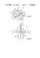
- FIG. 1is a perspective view of a single loop embodiment in accordance with the teachings of the present invention.
- FIG. 2is a side view of the embodiment in FIG. 1.
- FIG. 3is a perspective view of the embodiment in FIG. 1 referencing a three-dimensional coordinate system.
- FIGS. 4a and 4bshow an alternate sensor embodiment mounted directly on the flow meter conduit.
- FIG. 5shows an alternate embodiment of the flow meter to that shown in FIGS. 1, 2 and 3.
- FIG. 6shows a two driver embodiment of the flow meter shown in FIG. 1.
- FIG. 7shows the relative reaction forces effecting the conduit loop.
- the preferred embodiment of the flow meter of this inventioncomprises a conduit or tube which is generally referenced by the numeral 10.
- This conduit 10is to be positioned "in line” within a defined fluid stream or pre-existing pipe line (not shown).
- the conduit 10is provided with an inlet 12 and an outlet 14 at respective ends.
- the inlet 12 and outlet 14are positioned substantially along a single axial line which is defined by the pre-existing pipe line and is referenced as the X-axis 16.
- the conduit 10is formed into a spiral which, as shown, forms a loop 18.
- the referenced coordinate system referred to in this textis shown in FIG. 3.
- the Y-axisis referred to by the numeral 20 and the Z-axis being 22 in the three dimensional system shown.
- the inlet portion 24 of the conduit 10 between the inlet 12 and loop 18 and its corresponding outlet portion 26 from the loop 18 to the outlet 14are formed through the use of gently bent portions which turn the direction of the fluid flow approximately 90° (when viewed from above the X-Z plane).
- These inlet and outlet portions 24, 26 of the spiral design in FIGS. 1, 2 and 3are formed to minimize restriction of the fluid flow through the conduit 10.
- the actual shape of these portions 24, 26will vary depending on conduit diameter, the intended working fluid and the length of the spiral of the loop along the X-axis 16.
- a mounting bracket 28is positioned at the center of the loop 18.
- Supporting arm 30extends radially from the mounting bracket 28 and is positioned substantially along the Y-axis 20 to a position directly adjacent to the periphery of the loop 18.
- a driving transducer 32is mounted on the end of support arm 30.
- the driver 32may be of any conventional design such as an electromagnetic coil excited by an alternating current (See FIG. 2).
- the driver 32when excited to oscillate the loop 18, imparts a deflection to the loop 18 substantially parallel to the X-axis 16.
- the oscillation of the loop 18induces the alternating change in the angular momentum of the fluid within the conduit 10.
- driver 32substantially deflects the loop 18 perpendicular to the Y-Z plane and about the Z-axis 22, although these references are not critical to the invention.
- the mounting bracket 28is supported on a beam 36 which passes through the center of the loop 18 and extends substantially along the X-axis 16 and is attached to the inlet 12 and the outlet 14. This structure references the driver 32 to a single point which is substantially at the center of the loop 18.
- the loop 18is substantially symmetrical about the reference beam 36 (and the X-axis 16) and, therefore, automatically compensates for thermal expansion of the conduit 10 due to temperature variations in the fluid or the environment. Expansion or contraction of the conduit loop 18 or the bent portions 24, 26 will result in equivalent changes in the loop's dimensions along its periphery and its position with respect to the X-axis 16.
- the plane of the loop 18need not be perpendicular to the X-axis 16 (FIGS. 1, 2 and 3).
- the only limitationis that the driver 32 deflects the conduit 10 in a direction which is substantially perpendicular to the flow within the loop 18 and at the same time parallel to the X-axis 16.
- Sensing transducers 38 and 40may be mounted radially from the mounting bracket 28 on support arms 39, 41, respectively. These sensors 38, 40 are, preferably, located at the position adjacent to the maximum measurable deflection of the loop 18 created by the reaction of the fluid to the transverse acceleration created by the driver 32. Typically this position is a along the circumference of the loop 18, approximately 90° from the driver 32. These sensors or switches may take any known form such as linear, optical, etc.
- a piezo transducer type sensor 38', 40'may be directly attached to the loop 18 (as shown in FIG. 8) or mounted by a clip (not shown) rather than be supported on arms 39, 41.
- any type sensing mechanismmay be utilized these piezo self referencing sensors, which are accelerometers, are preferred.
- This type of sensing transducerparticularly shown in FIGS. 4a and 4b, converts high mechanical vibrational energy into an electrical pulse where the relative motion of the loop 18 becomes proportional to the acceleration of the tube 10 at the reference position.
- the piezo transduceris generally used together with a low pass filter to eliminate vibrational frequency components in the neighborhood of the natural resonance frequency. Such filtering may be performed simultaneously by a microprocessor while calculating the mass flow calculations.
- FIGS. 4a and 4bThe mechanical structure of a typical accelerometer is shown in FIGS. 4a and 4b.
- a ceramic body piece 42is formed with its electrical components 42a, 42b, 42c being mounted within a thick film or directly onto the only surface.
- the ends of the sensor 38are mounted to the conduit wall 10.
- the body 42is provided with a central, typically, tungsten filled epoxy mass 46.
- the central mass 46is mounted to a film which is supported on the body 42 by washer 48.
- the alternating deflections of the loop 18 due to the reaction forces of the fluidmove the central mass 46 in alternating directions placing the piezo element crystal in alternating tension and compression modes.
- the output of this arrangementproduces an electrical signal simulating the deflection signature of the fluid reaction forces on the conduit 10.
- the physical dimensions of the loopbe such that its natural resonant frequency does not correspond to the resonant frequencies of machinery found in the surrounding environment or utilized in the process line.
- Typical industrial machineryoperates at a resident frequency of 50-60 Hz.
- the combination of these environmental vibrations on the operating flow metermay create substantial discrepancies in the measurements of the sensing transducers 38, 40.
- FIGS. 5 and 6show, generally, a loop 18 and 118, respectively, formed substantially in a single plane (Y-Z plane).
- the imparted oscillation created by the driver(s) 32 in these figuresis parallel to the X-axis 16, perpendicular to the fluid flow within the loop 18 and 118 and substantially perpendicular to the Y-Z plane.
- the deflections of both sides of the loopare basically away from the Y-Z plane although this plane is not particularly referenced by the sensors.
- the embodiment in FIG. 6includes a second driver 32' which is mounted from the bracket 28 by a second support arm 30'.
- the two driversimpart 32, 32' deflections of the single plane loop 18' such that the loop 18' is deflected substantially simultaneously away from the Z-axis 22. Again, this axis is not referenced by the sensors 38', 40' for a proper calculation of the mass flow.
- Both embodiments of the flow meter in FIGS. 5 and 6utilize the substantially free floating loop design having a reduced spring constant.
- the torsional bending of the loop 18'is reduced as compared to the alternate embodiment 18 (in FIGS. 1-3) since the conduit is in the same plane and not spiraled about the X-axis.
- FIG. 9shows the integrated reaction forces (Fm and Fm') on the loop 18 in response to the transverse imparted deflection (VC).
- This integrated reaction force (Fm)is basically the same for all embodiments shown in the drawings and creates a torque (Tm) substantially about the Y-axis 20.
- a fluid streamis supplied to the inlet 12, travels around loop 18, and is returned into the stream through the outlet 14.
- the fluidis subject to an alternating transverse acceleration caused to the loop 18 by the excitation of the driver 32.
- a maximum deflectionoccurs in one direction and then a reverse deflection occurs to a similar maximum.
- the transverse acceleration imparted to the fluid flowing in the conduit 10results in reaction force which deflects the loop 18, on opposite sides of the driver 32, away from its stationary position.
- the sensors 38, 40(or 38', 40') are preferably positioned at points of maximum displacement of the loop 18 caused by this fluid reaction force.
- the deflection of the loopis measured with respect to time in order to determine the signature of both sides of the loop 18 due to the oscilating accelertion force.
- the transverse acceleration of the flowing mass within the loop 18will cause a differential deflection on opposite sides of the driver 32.
- the deflection of the loop 18 between the inlet portion 24 and the driver 32will lag or lead the deflection between the driver 32 and the outlet portion 26 depending on the oscillation directions. This is due to the spatial accelerations and decelerations of the mass flow in these respective loop 18 segments.
- the signature information provided by the sensors 38, 40 with respect to this phase motion of the loop 18is fed into a microprocessor. Noise vibrations can be removed simultaneously from these signals as can an indication of the validity of the signature cycle.
- the sensor datamay then be directly correlated to determine the mass flow.
- Each of these calculations and electronic filteringscan be performed by any suitable technique.
- Suitable sensing meanscan be of either the analog or digital type.
- Analog sensorsare used to measure the phase difference of the differential deflection of the two sides of the loop 18.
- Information relating to the phase of the two simultaneous outputscancels the effects of structural changes in the physical positioning of a loop 18 with respect to the sensing system.
- This type sensing systemdynamically responds to structure variations in the flow meter due to the changes in ambient conditions and, also, to common dynamic continuous or spike vibrational effects.
- the electrical circuitry utilized to control the energization of the driving transducers and to measure the loop 18 deflections, its time phase relationship to the driving force, and to receive and process the resulting signalsmay be performed in a microprocessor.
- the driver circuitis a conventional mechanical feedback multivibrator which runs at the resonant frequency of the mass being driven.
- a MOSFET bridgeexcites the coil which drives the magnet.
- Conventional coil/acceleometer feedbackcan be used but a combination of piezo/coil or piezo/crystal can be used to eliminate some electromagnetic common mode noise.
- the narrow band filters at the output of the piezo x-tal type preampshould be very tightly matched in characteristics and physically tied together for temperature tracking, so that any phase shift in the filters will be identical and the integrity of the desired mechanical phase shift is maintained.
Landscapes
- Physics & Mathematics (AREA)
- Fluid Mechanics (AREA)
- General Physics & Mathematics (AREA)
- Measuring Volume Flow (AREA)
Abstract
Description
Claims (14)
Priority Applications (1)
| Application Number | Priority Date | Filing Date | Title |
|---|---|---|---|
| US06/809,658US4733569A (en) | 1985-12-16 | 1985-12-16 | Mass flow meter |
Applications Claiming Priority (1)
| Application Number | Priority Date | Filing Date | Title |
|---|---|---|---|
| US06/809,658US4733569A (en) | 1985-12-16 | 1985-12-16 | Mass flow meter |
Publications (1)
| Publication Number | Publication Date |
|---|---|
| US4733569Atrue US4733569A (en) | 1988-03-29 |
Family
ID=25201899
Family Applications (1)
| Application Number | Title | Priority Date | Filing Date |
|---|---|---|---|
| US06/809,658Expired - LifetimeUS4733569A (en) | 1985-12-16 | 1985-12-16 | Mass flow meter |
Country Status (1)
| Country | Link |
|---|---|
| US (1) | US4733569A (en) |
Cited By (40)
| Publication number | Priority date | Publication date | Assignee | Title |
|---|---|---|---|---|
| US4856346A (en)* | 1986-11-13 | 1989-08-15 | K-Flow Division Of Kane Steel Company, Inc. | Dual flexures for coriolis type mass flow meters |
| US4891991A (en)* | 1986-10-28 | 1990-01-09 | The Foxboro Company | Coriolis-type mass flowmeter |
| US4957005A (en)* | 1989-10-05 | 1990-09-18 | Fischer & Porter Company | Coriolis-type flowmeter |
| US5073208A (en)* | 1989-09-14 | 1991-12-17 | K-Flow Corporation | Method for cryogenic treatment of Coriolis mass flow meter structures |
| US5115683A (en)* | 1988-09-27 | 1992-05-26 | K-Flow Division Of Kane Steel Co., Inc. | Coriolis mass flow meter adapted for low flow rates |
| US5271281A (en)* | 1986-10-28 | 1993-12-21 | The Foxboro Company | Coriolis-type mass flowmeter |
| US5343764A (en)* | 1986-10-28 | 1994-09-06 | The Foxboro Company | Coriolis-type mass flowmeter |
| US5373745A (en)* | 1991-02-05 | 1994-12-20 | Direct Measurement Corporation | Single path radial mode Coriolis mass flow rate meter |
| WO1995007445A1 (en)* | 1993-09-11 | 1995-03-16 | Endress + Hauser Flowtec Ag | Coriolis mass flow sensor with helical measurement tube |
| US5423221A (en)* | 1986-02-11 | 1995-06-13 | Abb K-Flow Inc. | Mass flow measuring device |
| US5423225A (en)* | 1991-02-05 | 1995-06-13 | Direct Measurement Corp. | Single path radial mode coriolis mass flow rate meter |
| US5473949A (en)* | 1991-02-05 | 1995-12-12 | Direct Measurement Corporation | Coriolis mass flow rate meter having adjustable pressure and density sensitivity |
| US5546814A (en)* | 1994-10-26 | 1996-08-20 | The Foxboro Company | Parallel-flow coriolis-type mass flowmeter with flow-dividing manifold |
| US5576500A (en)* | 1991-02-05 | 1996-11-19 | Direct Measurement Corporation | Coriolis mass flow rate meter having means for modifying angular velocity gradient positioned within a conduit |
| EP0763720A1 (en)* | 1995-09-13 | 1997-03-19 | Endress + Hauser Flowtec AG | Helical Coriolis mass flow sensor |
| US5753827A (en)* | 1995-10-17 | 1998-05-19 | Direct Measurement Corporation | Coriolis meteR having a geometry insensitive to changes in fluid pressure and density and method of operation thereof |
| US5827979A (en)* | 1996-04-22 | 1998-10-27 | Direct Measurement Corporation | Signal processing apparati and methods for attenuating shifts in zero intercept attributable to a changing boundary condition in a Coriolis mass flow meter |
| US5857893A (en)* | 1996-10-02 | 1999-01-12 | Speedfam Corporation | Methods and apparatus for measuring and dispensing processing solutions to a CMP machine |
| WO1999017018A1 (en)* | 1997-09-30 | 1999-04-08 | Vladimir Kangas | Closed system |
| US5907104A (en)* | 1995-12-08 | 1999-05-25 | Direct Measurement Corporation | Signal processing and field proving methods and circuits for a coriolis mass flow meter |
| CN1058565C (en)* | 1990-06-08 | 2000-11-15 | 微运转机械股份有限公司 | Improved stability coriolis mass flow meter |
| US6227059B1 (en) | 1999-01-12 | 2001-05-08 | Direct Measurement Corporation | System and method for employing an imaginary difference signal component to compensate for boundary condition effects on a Coriolis mass flow meter |
| US6513393B1 (en) | 1998-12-11 | 2003-02-04 | Flowtec Ag | Coriolis mass/flow density meter |
| DE4138840C2 (en)* | 1991-11-26 | 2003-02-06 | Abb Patent Gmbh | Holder for a pipe to be flowed through in a mass flow meter |
| WO2003100354A3 (en)* | 2002-05-24 | 2004-11-18 | Siemens Flow Instr As | Mass flowmeter with integration of acceleration forces on a tube and system using the mass flowmeter |
| US20050229719A1 (en)* | 2004-03-19 | 2005-10-20 | Endress + Hauser Flowtec Ag | Coriolis mass measuring device |
| US20060086196A1 (en)* | 2004-03-19 | 2006-04-27 | Endress + Hauser Flowtec Ag | In-line measuring device |
| WO2007036418A1 (en) | 2005-09-27 | 2007-04-05 | Endress+Hauser Flowtec Ag | Process for measuring a medium flowing in a pipe, and also measurement system therefor |
| US20070144234A1 (en)* | 2003-04-08 | 2007-06-28 | Invensys Systems, Inc. | Flowmeter calibration techniques |
| US20070180929A1 (en)* | 2005-12-27 | 2007-08-09 | Endress + Hauser Flowtec Ag | In-line measuring devices and method for compensation measurement errors in In-line measuring devices |
| US20070186686A1 (en)* | 2005-12-27 | 2007-08-16 | Endress + Hauser Flowtec Ag | In-Line measuring devices and method for compensation measurement errors in in-line measuring devices |
| DE102006062600A1 (en) | 2006-12-29 | 2008-07-03 | Endress + Hauser Flowtec Ag | Inline measuring device starting and/or monitoring method for use in measuring system, involves detecting momentary inclination of measuring sensor corresponding to inclination of principal axis of sensor opposite to intended reference axis |
| EP2026042A1 (en) | 2005-12-27 | 2009-02-18 | Endress+Hauser Flowtec AG | In-line measuring devices and method for compensating measurement errors in in-line measuring devices |
| DE102008016235A1 (en) | 2008-03-27 | 2009-10-01 | Endress + Hauser Flowtec Ag | A method of operating a meter disposed on a rotary carousel filling machine |
| US20100160871A1 (en)* | 2008-12-24 | 2010-06-24 | Charles Alan Seegert | Reduced-pressure treatment systems and methods employing debridement mechanisms |
| US9014997B2 (en) | 1997-11-26 | 2015-04-21 | Invensys Systems, Inc. | Drive techniques for a digital flowmeter |
| US9021892B2 (en) | 1999-11-22 | 2015-05-05 | Invensys Systems, Inc. | Correcting for two-phase flow in a digital flowmeter |
| US9046400B2 (en) | 1997-11-26 | 2015-06-02 | Invensys Systems, Inc. | Digital flowmeter |
| DE102004018326B4 (en) | 2004-04-13 | 2023-02-23 | Endress + Hauser Flowtec Ag | Device and method for measuring a density and/or a viscosity of a fluid |
| DE102021131866A1 (en) | 2021-12-03 | 2023-06-07 | Endress+Hauser Flowtec Ag | Method for detecting a foreign body in a medium |
Citations (39)
| Publication number | Priority date | Publication date | Assignee | Title |
|---|---|---|---|---|
| SU146982A1 (en)* | ||||
| US31450A (en)* | 1861-02-19 | Improvement in tools used in the manufacture of iron | ||
| US2624198A (en)* | 1949-09-08 | 1953-01-06 | Sun Oil Co | Flowmeter |
| US2811854A (en)* | 1955-07-14 | 1957-11-05 | Detroit Controls Corp | Low deflection mass flowmeter |
| US2813423A (en)* | 1954-09-07 | 1957-11-19 | Detroit Controls Corp | Gyroscopic mass flowmeter |
| US2819437A (en)* | 1954-11-01 | 1958-01-07 | American Radiator & Standard | Electrical measuring circuits for mass flowmeters |
| US2821084A (en)* | 1954-09-07 | 1958-01-28 | American Radiator & Standard | Flow control devices for flowmeters |
| US2831349A (en)* | 1954-09-07 | 1958-04-22 | American Radiator & Standard | Square gyroscopic flowmeter |
| US2834209A (en)* | 1954-10-06 | 1958-05-13 | American Radiator & Standard | Gyroscopic flowmeter |
| US2865201A (en)* | 1954-08-26 | 1958-12-23 | Roth Wilfred | Gyroscopic mass flowmeter |
| SU149900A1 (en)* | 1961-11-29 | 1961-11-30 | Л.В. Потемкин | Vibration gyroscopic flow meter |
| US3087325A (en)* | 1961-08-07 | 1963-04-30 | Roth Wilfred | Gyroscopic mass flowmeters |
| US3108475A (en)* | 1961-02-13 | 1963-10-29 | Wilfred Roth | Gyroscopic mass flowmeter |
| US3132512A (en)* | 1961-02-13 | 1964-05-12 | Roth Wilfred | Gyroscopic mass flowmeter |
| US3218851A (en)* | 1961-05-24 | 1965-11-23 | Anatole J Sipin | Mass flowmeter systems |
| US3261205A (en)* | 1961-05-24 | 1966-07-19 | Anatole J Sipia | Mass flow metering means |
| US3276257A (en)* | 1960-02-02 | 1966-10-04 | Roth Wilfred | Gyroscopic mass flowmeters |
| US3329019A (en)* | 1964-10-26 | 1967-07-04 | Anatole J Sipin | Mass flow metering means |
| US3355944A (en)* | 1964-09-03 | 1967-12-05 | Anatole J Sipin | Mass flow metering means |
| US3396579A (en)* | 1965-05-28 | 1968-08-13 | Souriau Daniel | Mass flowmeter |
| US3456491A (en)* | 1966-10-22 | 1969-07-22 | Siegfried Brockhaus | Device for measuring the density of a fluid |
| US3485098A (en)* | 1964-09-03 | 1969-12-23 | Anatole J Sipin | Mass flow metering means |
| US3896619A (en)* | 1972-05-05 | 1975-07-29 | Us Army | Earth spin axis detecting platform using coriolis acceleration detectors |
| US3927565A (en)* | 1973-01-30 | 1975-12-23 | Bertin & Cie | Apparatus and method for measuring the mass flow of a fluid stream |
| US4109524A (en)* | 1975-06-30 | 1978-08-29 | S & F Associates | Method and apparatus for mass flow rate measurement |
| US4127028A (en)* | 1977-06-07 | 1978-11-28 | Halliburton Company | Coriolis mass flow rate metering means |
| US4187721A (en)* | 1977-07-25 | 1980-02-12 | S & F Associates | Method and structure for flow measurement |
| US4192184A (en)* | 1978-11-13 | 1980-03-11 | Halliburton Company | Mass flowmeter |
| SU732672A1 (en)* | 1978-05-25 | 1980-05-05 | Калининградское Высшее Инженерное Училище Инженерных Войск Им. А.А. Жданова | Resonance flow meter |
| US4252028A (en)* | 1979-02-26 | 1981-02-24 | S & F Associates | Method and apparatus for measuring flow |
| US4311054A (en)* | 1978-11-13 | 1982-01-19 | Halliburton Company | Mass flowmeter with sensor gain control |
| US4381680A (en)* | 1980-12-29 | 1983-05-03 | St Lab., Inc. | Mass flow meter |
| USRE31450E (en) | 1977-07-25 | 1983-11-29 | Micro Motion, Inc. | Method and structure for flow measurement |
| US4422338A (en)* | 1981-02-17 | 1983-12-27 | Micro Motion, Inc. | Method and apparatus for mass flow measurement |
| US4444059A (en)* | 1982-09-13 | 1984-04-24 | Micro Motion | Oscillating tube mass flow rate meter |
| US4470294A (en)* | 1982-10-07 | 1984-09-11 | The United States Of America As Represented By The United States Department Of Energy | Method and apparatus for simultaneous determination of fluid mass flow rate, mean velocity and density |
| US4491025A (en)* | 1982-11-03 | 1985-01-01 | Micro Motion, Inc. | Parallel path Coriolis mass flow rate meter |
| US4491009A (en)* | 1983-06-10 | 1985-01-01 | Micro Motion, Inc. | Electronic circuit for vibrating tube densimeter |
| US4559833A (en)* | 1982-09-30 | 1985-12-24 | Smith Meter Inc. | Meter for measuring mass flow rate |
- 1985
- 1985-12-16USUS06/809,658patent/US4733569A/ennot_activeExpired - Lifetime
Patent Citations (41)
| Publication number | Priority date | Publication date | Assignee | Title |
|---|---|---|---|---|
| US31450A (en)* | 1861-02-19 | Improvement in tools used in the manufacture of iron | ||
| SU146982A1 (en)* | ||||
| US2624198A (en)* | 1949-09-08 | 1953-01-06 | Sun Oil Co | Flowmeter |
| US2865201A (en)* | 1954-08-26 | 1958-12-23 | Roth Wilfred | Gyroscopic mass flowmeter |
| US2821084A (en)* | 1954-09-07 | 1958-01-28 | American Radiator & Standard | Flow control devices for flowmeters |
| US2831349A (en)* | 1954-09-07 | 1958-04-22 | American Radiator & Standard | Square gyroscopic flowmeter |
| US2813423A (en)* | 1954-09-07 | 1957-11-19 | Detroit Controls Corp | Gyroscopic mass flowmeter |
| US2834209A (en)* | 1954-10-06 | 1958-05-13 | American Radiator & Standard | Gyroscopic flowmeter |
| US2819437A (en)* | 1954-11-01 | 1958-01-07 | American Radiator & Standard | Electrical measuring circuits for mass flowmeters |
| US2811854A (en)* | 1955-07-14 | 1957-11-05 | Detroit Controls Corp | Low deflection mass flowmeter |
| US3276257A (en)* | 1960-02-02 | 1966-10-04 | Roth Wilfred | Gyroscopic mass flowmeters |
| US3132512A (en)* | 1961-02-13 | 1964-05-12 | Roth Wilfred | Gyroscopic mass flowmeter |
| US3108475A (en)* | 1961-02-13 | 1963-10-29 | Wilfred Roth | Gyroscopic mass flowmeter |
| US3261205A (en)* | 1961-05-24 | 1966-07-19 | Anatole J Sipia | Mass flow metering means |
| US3218851A (en)* | 1961-05-24 | 1965-11-23 | Anatole J Sipin | Mass flowmeter systems |
| US3087325A (en)* | 1961-08-07 | 1963-04-30 | Roth Wilfred | Gyroscopic mass flowmeters |
| SU149900A1 (en)* | 1961-11-29 | 1961-11-30 | Л.В. Потемкин | Vibration gyroscopic flow meter |
| US3485098A (en)* | 1964-09-03 | 1969-12-23 | Anatole J Sipin | Mass flow metering means |
| US3355944A (en)* | 1964-09-03 | 1967-12-05 | Anatole J Sipin | Mass flow metering means |
| US3329019A (en)* | 1964-10-26 | 1967-07-04 | Anatole J Sipin | Mass flow metering means |
| US3396579A (en)* | 1965-05-28 | 1968-08-13 | Souriau Daniel | Mass flowmeter |
| US3456491A (en)* | 1966-10-22 | 1969-07-22 | Siegfried Brockhaus | Device for measuring the density of a fluid |
| US3896619A (en)* | 1972-05-05 | 1975-07-29 | Us Army | Earth spin axis detecting platform using coriolis acceleration detectors |
| US3927565A (en)* | 1973-01-30 | 1975-12-23 | Bertin & Cie | Apparatus and method for measuring the mass flow of a fluid stream |
| US4109524A (en)* | 1975-06-30 | 1978-08-29 | S & F Associates | Method and apparatus for mass flow rate measurement |
| US4127028A (en)* | 1977-06-07 | 1978-11-28 | Halliburton Company | Coriolis mass flow rate metering means |
| US4187721A (en)* | 1977-07-25 | 1980-02-12 | S & F Associates | Method and structure for flow measurement |
| USRE31450E (en) | 1977-07-25 | 1983-11-29 | Micro Motion, Inc. | Method and structure for flow measurement |
| SU732672A1 (en)* | 1978-05-25 | 1980-05-05 | Калининградское Высшее Инженерное Училище Инженерных Войск Им. А.А. Жданова | Resonance flow meter |
| US4311054A (en)* | 1978-11-13 | 1982-01-19 | Halliburton Company | Mass flowmeter with sensor gain control |
| US4192184A (en)* | 1978-11-13 | 1980-03-11 | Halliburton Company | Mass flowmeter |
| US4252028A (en)* | 1979-02-26 | 1981-02-24 | S & F Associates | Method and apparatus for measuring flow |
| US4381680A (en)* | 1980-12-29 | 1983-05-03 | St Lab., Inc. | Mass flow meter |
| US4422338A (en)* | 1981-02-17 | 1983-12-27 | Micro Motion, Inc. | Method and apparatus for mass flow measurement |
| US4422338B1 (en)* | 1981-02-17 | 1987-07-14 | ||
| US4444059A (en)* | 1982-09-13 | 1984-04-24 | Micro Motion | Oscillating tube mass flow rate meter |
| US4559833A (en)* | 1982-09-30 | 1985-12-24 | Smith Meter Inc. | Meter for measuring mass flow rate |
| US4470294A (en)* | 1982-10-07 | 1984-09-11 | The United States Of America As Represented By The United States Department Of Energy | Method and apparatus for simultaneous determination of fluid mass flow rate, mean velocity and density |
| US4491025A (en)* | 1982-11-03 | 1985-01-01 | Micro Motion, Inc. | Parallel path Coriolis mass flow rate meter |
| US4491025B1 (en)* | 1982-11-03 | 1988-01-05 | ||
| US4491009A (en)* | 1983-06-10 | 1985-01-01 | Micro Motion, Inc. | Electronic circuit for vibrating tube densimeter |
Non-Patent Citations (14)
| Title |
|---|
| Alan M. Young, "Coriolis-Based Mass Flow Meter", Dec. 1985-Sensors Magazine. |
| Alan M. Young, Coriolis Based Mass Flow Meter , Dec. 1985 Sensors Magazine.* |
| Danfoss Co., "MASSFLO". |
| Danfoss Co., MASSFLO .* |
| E. Dahlin, A. Young, R. Blake, C. Guggenheim, S. Kaiser and A. Levien, "Mass Flow Meter"-Measurement and Controls magazine. |
| E. Dahlin, A. Young, R. Blake, C. Guggenheim, S. Kaiser and A. Levien, Mass Flow Meter Measurement and Controls magazine.* |
| Exac Corp., Digital Precision Mass Flow Meter.* |
| Instrument Engineers Handbook (Rev. Ed.), Mass Flow Meters (pp. 87 90), 1982.* |
| Instrument Engineers Handbook (Rev. Ed.), Mass Flow Meters (pp. 87-90), 1982. |
| Micro Motion, Model D25.* |
| Smith Meter Co., "S-MASS", 1985. |
| Smith Meter Co., S MASS , 1985.* |
| W. Bye, "Mass Flow Measured with Vibration Generators", Feb. 1957-Fluid Handling magazine. |
| W. Bye, Mass Flow Measured with Vibration Generators , Feb. 1957 Fluid Handling magazine.* |
Cited By (61)
| Publication number | Priority date | Publication date | Assignee | Title |
|---|---|---|---|---|
| US5551307A (en)* | 1986-02-11 | 1996-09-03 | Abb K-Flow Inc. | Mass flow measuring device |
| US5423221A (en)* | 1986-02-11 | 1995-06-13 | Abb K-Flow Inc. | Mass flow measuring device |
| US4891991A (en)* | 1986-10-28 | 1990-01-09 | The Foxboro Company | Coriolis-type mass flowmeter |
| US5271281A (en)* | 1986-10-28 | 1993-12-21 | The Foxboro Company | Coriolis-type mass flowmeter |
| US5343764A (en)* | 1986-10-28 | 1994-09-06 | The Foxboro Company | Coriolis-type mass flowmeter |
| US4856346A (en)* | 1986-11-13 | 1989-08-15 | K-Flow Division Of Kane Steel Company, Inc. | Dual flexures for coriolis type mass flow meters |
| US5115683A (en)* | 1988-09-27 | 1992-05-26 | K-Flow Division Of Kane Steel Co., Inc. | Coriolis mass flow meter adapted for low flow rates |
| US5073208A (en)* | 1989-09-14 | 1991-12-17 | K-Flow Corporation | Method for cryogenic treatment of Coriolis mass flow meter structures |
| US4957005A (en)* | 1989-10-05 | 1990-09-18 | Fischer & Porter Company | Coriolis-type flowmeter |
| CN1058565C (en)* | 1990-06-08 | 2000-11-15 | 微运转机械股份有限公司 | Improved stability coriolis mass flow meter |
| US5423225A (en)* | 1991-02-05 | 1995-06-13 | Direct Measurement Corp. | Single path radial mode coriolis mass flow rate meter |
| US5497665A (en)* | 1991-02-05 | 1996-03-12 | Direct Measurement Corporation | Coriolis mass flow rate meter having adjustable pressure and density sensitivity |
| US5473949A (en)* | 1991-02-05 | 1995-12-12 | Direct Measurement Corporation | Coriolis mass flow rate meter having adjustable pressure and density sensitivity |
| US5576500A (en)* | 1991-02-05 | 1996-11-19 | Direct Measurement Corporation | Coriolis mass flow rate meter having means for modifying angular velocity gradient positioned within a conduit |
| US5373745A (en)* | 1991-02-05 | 1994-12-20 | Direct Measurement Corporation | Single path radial mode Coriolis mass flow rate meter |
| DE4138840C2 (en)* | 1991-11-26 | 2003-02-06 | Abb Patent Gmbh | Holder for a pipe to be flowed through in a mass flow meter |
| WO1995007445A1 (en)* | 1993-09-11 | 1995-03-16 | Endress + Hauser Flowtec Ag | Coriolis mass flow sensor with helical measurement tube |
| US5557973A (en)* | 1993-09-11 | 1996-09-24 | Endress + Hauser Flowtec Ag | Coriolis-type mass flow sensor with a helical measuring tube |
| US5546814A (en)* | 1994-10-26 | 1996-08-20 | The Foxboro Company | Parallel-flow coriolis-type mass flowmeter with flow-dividing manifold |
| EP0763720A1 (en)* | 1995-09-13 | 1997-03-19 | Endress + Hauser Flowtec AG | Helical Coriolis mass flow sensor |
| US5675093A (en)* | 1995-09-13 | 1997-10-07 | Endress+Hauser Flowtec Ag | Coriolis mass flow sensor including a single connection and support structure |
| US5753827A (en)* | 1995-10-17 | 1998-05-19 | Direct Measurement Corporation | Coriolis meteR having a geometry insensitive to changes in fluid pressure and density and method of operation thereof |
| US5907104A (en)* | 1995-12-08 | 1999-05-25 | Direct Measurement Corporation | Signal processing and field proving methods and circuits for a coriolis mass flow meter |
| US5827979A (en)* | 1996-04-22 | 1998-10-27 | Direct Measurement Corporation | Signal processing apparati and methods for attenuating shifts in zero intercept attributable to a changing boundary condition in a Coriolis mass flow meter |
| US5857893A (en)* | 1996-10-02 | 1999-01-12 | Speedfam Corporation | Methods and apparatus for measuring and dispensing processing solutions to a CMP machine |
| US6321783B1 (en) | 1997-09-03 | 2001-11-27 | Hillar Neem | Closed system motor |
| WO1999017018A1 (en)* | 1997-09-30 | 1999-04-08 | Vladimir Kangas | Closed system |
| US9200936B2 (en) | 1997-11-26 | 2015-12-01 | Invensys Systems, Inc. | Digital flowmeter |
| US9080909B2 (en) | 1997-11-26 | 2015-07-14 | Invensys Systems, Inc. | Digital flowmeter |
| US9014997B2 (en) | 1997-11-26 | 2015-04-21 | Invensys Systems, Inc. | Drive techniques for a digital flowmeter |
| US9046401B2 (en) | 1997-11-26 | 2015-06-02 | Invensys Systems, Inc. | Correcting for two-phase flow in a digital flowmeter |
| US9279710B2 (en) | 1997-11-26 | 2016-03-08 | Invensys Systems, Inc. | Digital flowmeter |
| US9046400B2 (en) | 1997-11-26 | 2015-06-02 | Invensys Systems, Inc. | Digital flowmeter |
| US9091580B2 (en) | 1997-11-26 | 2015-07-28 | Invensys Systems, Inc. | Digital flowmeter |
| US6513393B1 (en) | 1998-12-11 | 2003-02-04 | Flowtec Ag | Coriolis mass/flow density meter |
| US6227059B1 (en) | 1999-01-12 | 2001-05-08 | Direct Measurement Corporation | System and method for employing an imaginary difference signal component to compensate for boundary condition effects on a Coriolis mass flow meter |
| US9021892B2 (en) | 1999-11-22 | 2015-05-05 | Invensys Systems, Inc. | Correcting for two-phase flow in a digital flowmeter |
| WO2003100354A3 (en)* | 2002-05-24 | 2004-11-18 | Siemens Flow Instr As | Mass flowmeter with integration of acceleration forces on a tube and system using the mass flowmeter |
| US20070144234A1 (en)* | 2003-04-08 | 2007-06-28 | Invensys Systems, Inc. | Flowmeter calibration techniques |
| US7690240B2 (en)* | 2003-04-08 | 2010-04-06 | Invensys Systems, Inc. | Flowmeter calibration techniques |
| US20100307220A1 (en)* | 2003-04-08 | 2010-12-09 | Invensys Systems, Inc. | Flowmeter calibration techniques |
| US20050229719A1 (en)* | 2004-03-19 | 2005-10-20 | Endress + Hauser Flowtec Ag | Coriolis mass measuring device |
| US20070137313A1 (en)* | 2004-03-19 | 2007-06-21 | Endress + Hauser Flowtec Ag | In-line measuring device |
| US20060086196A1 (en)* | 2004-03-19 | 2006-04-27 | Endress + Hauser Flowtec Ag | In-line measuring device |
| US7040181B2 (en) | 2004-03-19 | 2006-05-09 | Endress + Hauser Flowtec Ag | Coriolis mass measuring device |
| US7284449B2 (en) | 2004-03-19 | 2007-10-23 | Endress + Hauser Flowtec Ag | In-line measuring device |
| US7296484B2 (en) | 2004-03-19 | 2007-11-20 | Endress + Hauser Flowtec Ag | In-line measuring device |
| US7357039B2 (en) | 2004-03-19 | 2008-04-15 | Endress + Hauser Flowtec Ag | Coriolis mass measuring device |
| DE102004018326B4 (en) | 2004-04-13 | 2023-02-23 | Endress + Hauser Flowtec Ag | Device and method for measuring a density and/or a viscosity of a fluid |
| EP2772730A1 (en) | 2005-09-27 | 2014-09-03 | Endress + Hauser Flowtec AG | Process for measuring a medium flowing in a pipe and measurement system therefor |
| WO2007036418A1 (en) | 2005-09-27 | 2007-04-05 | Endress+Hauser Flowtec Ag | Process for measuring a medium flowing in a pipe, and also measurement system therefor |
| EP2026042A1 (en) | 2005-12-27 | 2009-02-18 | Endress+Hauser Flowtec AG | In-line measuring devices and method for compensating measurement errors in in-line measuring devices |
| US7360453B2 (en) | 2005-12-27 | 2008-04-22 | Endress + Hauser Flowtec Ag | In-line measuring devices and method for compensation measurement errors in in-line measuring devices |
| US20070186686A1 (en)* | 2005-12-27 | 2007-08-16 | Endress + Hauser Flowtec Ag | In-Line measuring devices and method for compensation measurement errors in in-line measuring devices |
| US20070180929A1 (en)* | 2005-12-27 | 2007-08-09 | Endress + Hauser Flowtec Ag | In-line measuring devices and method for compensation measurement errors in In-line measuring devices |
| US7360452B2 (en) | 2005-12-27 | 2008-04-22 | Endress + Hauser Flowtec Ag | In-line measuring devices and method for compensation measurement errors in in-line measuring devices |
| DE102006062600A1 (en) | 2006-12-29 | 2008-07-03 | Endress + Hauser Flowtec Ag | Inline measuring device starting and/or monitoring method for use in measuring system, involves detecting momentary inclination of measuring sensor corresponding to inclination of principal axis of sensor opposite to intended reference axis |
| DE102008016235A1 (en) | 2008-03-27 | 2009-10-01 | Endress + Hauser Flowtec Ag | A method of operating a meter disposed on a rotary carousel filling machine |
| US20100160871A1 (en)* | 2008-12-24 | 2010-06-24 | Charles Alan Seegert | Reduced-pressure treatment systems and methods employing debridement mechanisms |
| DE102021131866A1 (en) | 2021-12-03 | 2023-06-07 | Endress+Hauser Flowtec Ag | Method for detecting a foreign body in a medium |
| WO2023099411A1 (en) | 2021-12-03 | 2023-06-08 | Endress+Hauser Flowtec Ag | Method for detecting a foreign body in a medium |
Similar Documents
| Publication | Publication Date | Title |
|---|---|---|
| US4733569A (en) | Mass flow meter | |
| US5349872A (en) | Stationary coils for a coriolis effect mass flowmeter | |
| US4716771A (en) | Symmetrical mass flow meter | |
| EP0196150B1 (en) | Fluid flow measurement | |
| US4895031A (en) | Sensor mounting for coriolis mass flow rate meter | |
| US6164140A (en) | Solid state transducer for Coriolis flowmeter | |
| EP0250706B1 (en) | Mass Flow Measuring Device | |
| CA2443375C (en) | Vibratory transducer | |
| JP2575203B2 (en) | Mass flow meter with improved accuracy by compensating for asymmetry and viscous damping | |
| EP0421812B1 (en) | Improved coriolis-type flowmeter | |
| JPH07239261A (en) | Mass-flow-rate measuring device | |
| US4972724A (en) | Coriolis-type mass flowmeter having a straight measuring tube | |
| EP0381302B1 (en) | Measuring mass flow rates of fluid flows | |
| JPH0769205B2 (en) | Coriolis mass flowmeter unaffected by density changes | |
| US4984472A (en) | Apparatus for mass flow rate and density measurement | |
| WO2000002019A1 (en) | A coriolis effect fluid flow meter | |
| US6178828B1 (en) | Free standing Coriolis driver | |
| JP3058094B2 (en) | Mass flow meter | |
| JPH067324Y2 (en) | Mass flow meter | |
| JPH0712612A (en) | Coriolis mass flowmeter | |
| USRE34006E (en) | Angular rate sensor | |
| EP0266215A2 (en) | Frequency sensing devices | |
| RU2316734C2 (en) | Method and device for balancing coriolis flow meter | |
| JPH0436409Y2 (en) | ||
| JPH0431716A (en) | Karman vortex sensor |
Legal Events
| Date | Code | Title | Description |
|---|---|---|---|
| AS | Assignment | Owner name:K-FLOW DIVISION OF KANE STEEL CO., INC., MILLVILLE Free format text:ASSIGNMENT OF ASSIGNORS INTEREST.;ASSIGNOR:KANE, MARTIN;REEL/FRAME:004517/0773 Effective date:19860115 Owner name:K-FLOW DIVISION OF KANE STEEL CO., INC. MILLVILLE Free format text:ASSIGNMENT OF ASSIGNORS INTEREST.;ASSIGNOR:PRATT, WAYNE;REEL/FRAME:004517/0775 Effective date:19860124 Owner name:K-FLOW DIVISION OF KANE STEEL CO., INC. MILLVILLE Free format text:ASSIGNMENT OF ASSIGNORS INTEREST.;ASSIGNOR:KELSEY, NEWTON D.;REEL/FRAME:004517/0782 Effective date:19860102 Owner name:K-FLOW DIVISION OF KANE STEEL CO., INC., A CORP. O Free format text:ASSIGNMENT OF ASSIGNORS INTEREST;ASSIGNOR:KANE, MARTIN;REEL/FRAME:004517/0773 Effective date:19860115 Owner name:K-FLOW DIVISION OF KANE STEEL CO., INC., A CORP. O Free format text:ASSIGNMENT OF ASSIGNORS INTEREST;ASSIGNOR:PRATT, WAYNE;REEL/FRAME:004517/0775 Effective date:19860124 Owner name:K-FLOW DIVISION OF KANE STEEL CO., INC., A CORP. O Free format text:ASSIGNMENT OF ASSIGNORS INTEREST;ASSIGNOR:KELSEY, NEWTON D.;REEL/FRAME:004517/0782 Effective date:19860102 | |
| STCF | Information on status: patent grant | Free format text:PATENTED CASE | |
| FEPP | Fee payment procedure | Free format text:PAT HLDR NO LONGER CLAIMS SMALL ENT STAT AS SMALL BUSINESS (ORIGINAL EVENT CODE: LSM2); ENTITY STATUS OF PATENT OWNER: LARGE ENTITY Free format text:PAYOR NUMBER ASSIGNED (ORIGINAL EVENT CODE: ASPN); ENTITY STATUS OF PATENT OWNER: LARGE ENTITY | |
| FPAY | Fee payment | Year of fee payment:4 | |
| AS | Assignment | Owner name:K-FLOW CORPORATION, A CORP. OF NJ, NEW JERSEY Free format text:ASSIGNMENT OF ASSIGNORS INTEREST.;ASSIGNOR:KANE STEEL CO., INC., A CORP. OF NJ;REEL/FRAME:005829/0856 Effective date:19910827 | |
| AS | Assignment | Owner name:ABB K-FLOW INC., NEW JERSEY Free format text:CHANGE OF NAME;ASSIGNOR:K-FLOW CORPORATION;REEL/FRAME:006505/0126 Effective date:19930201 | |
| FPAY | Fee payment | Year of fee payment:8 | |
| AS | Assignment | Owner name:ABB KENT TAYLOR LIMITED, UNITED KINGDOM Free format text:ASSIGNMENT OF ASSIGNORS INTEREST;ASSIGNOR:ABB K-FLOW INC.;REEL/FRAME:008753/0309 Effective date:19971009 | |
| FPAY | Fee payment | Year of fee payment:12 |