US4733115A - Electric motor - Google Patents
Electric motorDownload PDFInfo
- Publication number
- US4733115A US4733115AUS06/942,121US94212186AUS4733115AUS 4733115 AUS4733115 AUS 4733115AUS 94212186 AUS94212186 AUS 94212186AUS 4733115 AUS4733115 AUS 4733115A
- Authority
- US
- United States
- Prior art keywords
- motor
- coil
- conductor
- layers
- elements
- Prior art date
- Legal status (The legal status is an assumption and is not a legal conclusion. Google has not performed a legal analysis and makes no representation as to the accuracy of the status listed.)
- Expired - Lifetime
Links
Images


Classifications
- H—ELECTRICITY
- H02—GENERATION; CONVERSION OR DISTRIBUTION OF ELECTRIC POWER
- H02K—DYNAMO-ELECTRIC MACHINES
- H02K3/00—Details of windings
- H02K3/04—Windings characterised by the conductor shape, form or construction, e.g. with bar conductors
- H02K3/26—Windings characterised by the conductor shape, form or construction, e.g. with bar conductors consisting of printed conductors
- H—ELECTRICITY
- H02—GENERATION; CONVERSION OR DISTRIBUTION OF ELECTRIC POWER
- H02K—DYNAMO-ELECTRIC MACHINES
- H02K29/00—Motors or generators having non-mechanical commutating devices, e.g. discharge tubes or semiconductor devices
- H02K29/06—Motors or generators having non-mechanical commutating devices, e.g. discharge tubes or semiconductor devices with position sensing devices
- H02K29/08—Motors or generators having non-mechanical commutating devices, e.g. discharge tubes or semiconductor devices with position sensing devices using magnetic effect devices, e.g. Hall-plates, magneto-resistors
- H—ELECTRICITY
- H05—ELECTRIC TECHNIQUES NOT OTHERWISE PROVIDED FOR
- H05K—PRINTED CIRCUITS; CASINGS OR CONSTRUCTIONAL DETAILS OF ELECTRIC APPARATUS; MANUFACTURE OF ASSEMBLAGES OF ELECTRICAL COMPONENTS
- H05K1/00—Printed circuits
- H05K1/16—Printed circuits incorporating printed electric components, e.g. printed resistor, capacitor, inductor
- H—ELECTRICITY
- H05—ELECTRIC TECHNIQUES NOT OTHERWISE PROVIDED FOR
- H05K—PRINTED CIRCUITS; CASINGS OR CONSTRUCTIONAL DETAILS OF ELECTRIC APPARATUS; MANUFACTURE OF ASSEMBLAGES OF ELECTRICAL COMPONENTS
- H05K1/00—Printed circuits
- H05K1/18—Printed circuits structurally associated with non-printed electric components
Definitions
- the present inventionrelates to an electric motor, and more particularly, to a brushless DC motor of the planar type.
- U.S. Pat. No. 4,340,833discloses an armature for a miniature motor in which spiral coils are arranged on opposite sides of an insulating sheet. The coils in the armature are connected in series, and the inner ends of opposing coils are connected to each other through the insulating sheet. The connections of the inner ends are made by spot welding.
- a problem with using coils of the type shown in this patentis that they must be mounted on a support, such as a printed circuit board, and then connected to the drive electronics for the motor. Such an arrangement increases the complexity and expense of the motor and also increases the possibility of malfunction due to a faulty connection.
- an electric motorcomprising: a generally planar rotor adapted to be rotated about an axis, the rotor being a multipolar permanent magnet; a generally planar stator axially spaced from the rotor, the stator including a motor coil disposed opposite the rotor and a control section formed integrally with the coil, the stator having a conductor layer extending through the coil and the control section, the conductor layer comprising elements of the coil and a conductor pattern in the control section which is electrically connected to the coil elements; and control elements connected to the conductor pattern to control current in the coil elements.
- the motorincludes a stator having a multilayer coil which is integrally formed with a multilayer control section. Electronic components are joined to a conductor pattern on a top layer of the control section to provide a means for regulating current to the coil.
- the statoris supported on a base plate, and a multipolar rotor is mounted for rotation closely adjacent the stator.
- a principal advantage of the present inventionis that it makes it possible to eliminate separate circuit boards and coil connectors in a planar motor of the type disclosed herein.
- the motorcan be made more compact and with less expense than in known motor constructions.
- the integrally-formed conductor patterns in the control sectionhave a low resistance, and they are not subject to coming loose during usage. Further, the printed conductor patterns facilitate the precise location of certain elements, such as the Hall sensors, which improves the performance of the motor.
- FIG. 1is an exploded perspective view of the motor of present invention in which the electronic control elements have been omitted;
- FIGS. 2-11show the formation of the various layers of the motor stator
- FIG. 12is a plan view of the motor stator, showing the arrangement of the electronic control elements
- FIG. 13is a plan view of the motor stator, showing the conductor pattern in the control section of the stator.
- FIG. 14is an elevational view, in section, of the motor of the present invention and a cylinder driven thereby.
- Motor 10constructed in accordance with the present invention.
- Motor 10comprises a stator 12, a base plate 14 which also serves as a bottom flux plate, a hub 16, a rotor 18, a top flux plate 20 and a guard 23.
- Stator 12includes a motor coil 25 and a control section 27.
- Motor 10, as described herein,is a three-phase, brushless DC motor.
- Rotor 18is a multipolar permanent magnet which includes sixteen poles 35.
- the permanent magnet of rotor 18interacts with a magnetic field produced by coil 25 when a current is supplied thereto to produce rotation of rotor 18.
- Both the poles 35 and coil elements 29 of coil 25are shaped as sectors so that the flux generated by a pole 35 effectively meets a coil element 29.
- Stator 12can be made by a process disclosed in a commonly-assigned patent application, Ser. No. 942,122, entitled Method of Making An Electronic Component, filed on even date herewith.
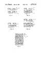
- an element in the form of a laminate 21(FIG. 6) is made in a first part of the process.
- a multilayer blank 22(FIG. 2) is used as a starting material.
- Blank 22comprises a conductor layer in the form of a copper layer 24, a layer 26 of positive resist adhered to one side of layer 24, and a dielectric layer 28 which is a negative resist adhered to an opposite side of layer 24.
- a removable cover sheet 30is placed over layer 28.
- Layer 24can be any electrically-conductive metal; however, a preferred metal is copper.
- Positive resist layer 26can be, for example, Kodak 809 positive resist, available from Eastman Kodak Co., Rochester, N.Y.
- the negative resist of layer 28can be a photopolymerizable plastic as disclosed, for example, in commonly-assigned U.S. Pat. No. 4,322,490, granted Mar. 30, 1982, and this patent is expressly incorporated herein by reference.
- Cover sheet 30can be formed, for example, from polyethylene terephthalate, obtainable from Eastman Kodak Co. under the trademark "Estar.”
- a blank 22 of a type which can be used in the present inventionis shown in U.S. Pat. No. 4,342,151, granted Aug. 3, 1982. Suitable thicknesses for the various layers in blank 22 are 0.002-0.005 inches for layer 26, 0.0007-0.006 inches for layer 24, 0.0005-0.005 inches for layer 28, and 0.001 inches for sheet 30.
- layer 28is exposed with ultraviolet light through a mask 32, and the layer 26 is simultaneously exposed with ultraviolet light through a mask 34.
- the ultraviolet lightcan be provided by mercury vapor lamps.
- the positive resist layer 26is developed using, for example, Kodak 809 developer in a 50% solution at about 30° C.
- the copper layer 24is then etched (FIG. 4) to form a desired conductor pattern in layer 24.
- the copper layer 24is etched using a solution of 2 M CuCl 2H 2 O and 2 M HCl, the solution having a pH of approximately minus 1.
- the resist layer 26is stripped off, using a 5% solution of sodium hydroxide (pH of approximately 13.6), leaving the combination shown in FIG. 5.
- the cover sheet 30is then removed, and the unexposed negative resist of layer 28 is developed in a 1,1,1-trichloroethane solution to produce a laminate 21 (FIG. 6).
- laminates 21are assembled together to form stator 12 having a plurality of copper layers 24.
- a dielectric adhesive 42is screen printed on a copper layer 24 of a laminate 21 in a pattern such that selected areas 44 of the conductive copper material are exposed.
- a conductive paste 46is applied to copper layer 24 through openings 47 in layer 28.
- the conductive paste 46is a pliable material which can be screen printed onto the layer 24; however a preferred method is to dispense the paste into openings 47.
- Laminates 21are then joined, as shown in FIG. 9. These steps are repeated (FIG. 10) to form stator 12 having six laminates 21, as shown in FIG. 11.
- stator 12When the stator 12 has been fully formed, it is cured for 10-60 minutes at a temperature of between about 150° C. and about 200° C. During the curing step, the laminates 21 of stator 12 are pressed together with a light pressure of 2-5 psi.
- the dielectric adhesive 42can be, for example, Cermalloy CL84-5133 dielectric adhesive, available from Heraeus-Cermalloy, West Conshohocken, Pa.
- the conductive paste 46can be a thermoplastic containing conductive particles or an epoxy plastic containing conductive particles.
- the conductive particlescan be, for example, silver or copper particles.
- a preferred conductive pasteis Marpoxy 98-240 paste which contains copper particles and is obtainable from Key Polymer Company.
- Other suitable conductive pastesare a conductive epoxy obtainable from Heraeus-Cermalloy under the tradename Cermalloy CL20-5328, and Amicon C9901 obtainable from the Amicon Company.
- An important consideration in selecting the dielectric adhesive 42 and the conductive paste 46is that they not contain solvents which would react with the other materials in laminate 21.
- each laminate 21comprises a dielectric layer 28 and a copper layer 24 which is formed into a plurality of coil elements 29 and a conductor pattern 37 (FIG. 1).
- Motor coil 25includes six copper layers 24 (FIG. 11), and each of the copper layers 24 is separated by a dielectric layer 28.
- Each copper layer 24includes a set of sixteen coil elements 29 (FIG. 12), and in a top pair of copper layers 24, when the layers are oriented as shown in FIG. 11, the coil elements 29 are superposed and are connected in series to form one phase of motor 10.
- the coil elements 29 in a middle pair of copper layers 24are superposed and connected in series to form a second phase of motor 10, and the coil elements 29 in a bottom pair of layers 24 are superposed and connected in series to form a third phase of motor 10.
- the coil elements 29 included in each phaseare displaced 15 degrees in a circumferential direction with respect to adjacent coil elements 29 included in another phase; that is, the coil elements 29 in the top pair of layers 24 are displaced 15 degrees with respect to the coil elements 29 in the middle pair of layers 24, and the coil elements 29 in the middle pair of layers 24 are displaced 15 degrees with respect to the coil elements 29 in the bottom pair of layers 24.
- Control section 27is formed from the same copper layers 24 and dielectric layers 28 that make up motor coil 25. As shown in FIG. 13, section 27 includes conductor patterns 37, formed in layers 24, and as shown in FIG. 12, control section 27 includes on a top layer thereof electronic control elements 31 which are necessary to control the flow of current to the three phases of motor 10. In FIG. 12, conductor pattern 37 has been omitted to more clearly show the arrangement of elements 31. In FIG. 13, a copper layer 24 of stator 12 is shown which includes coil elements 29 and a conductor pattern 37 for forming the electrical connections between motor coil 25 and the electronic control elements 31 shown in FIG. 12.
- each of the other copper layers 24 in control section 27contains a conductor pattern 37 and that all of the conductor patterns 37 are electrically connected to form part of a motor drive circuit.
- Each of the conductor patterns 37is formed such that a substantial portion of copper remains in a layer 24 in order to give rigidity to the stator 12.
- the motor drive ciruit(not shown), which controls the current to motor coil 25 and includes control elements 31, does not form a part of the present invention, and thus, a detailed explanation of the circuit will not be given herein.
- the electronic control elements 31are integrated circuit chips having input and output pins which are connected to the conductor patterns 37 in the layers 24.
- the control elements 31can be joined to a conductor pattern 37 in the control section 27 by any suitable material.
- One suitable materialis a conductive paste in the form of a silver-loaded epoxy.
- Another suitable materialis a reflow solder.
- terminals 41are provided in a conductor pattern 37 in a layer 24 for receiving Hall sensors (not shown). As is well known in the art, these sensors sense the angular position of rotor 18 in order to control the commutation of current between the individual phases of motor 10. When the Hall sensors are mounted on terminals 41, they are precisely located relative to rotor 18. The sensors are arranged to fit under a tapered portion 43 of rotor 18 (FIG. 14), and in this position, they are in an optimum location to sense the angular position of the rotor 18.
- motor 10is mounted to drive a cylinder 50.
- Hub 16, flux plate 20, and rotor 18are fixed to the cylinder 50 and are adapted to rotate therewith.
- a shaft 52 fixed to hub 16is supported in a bearing 54 which is mounted in a frame element 56.
- Stator 12 and base plate 14are also mounted on element 56.
Landscapes
- Engineering & Computer Science (AREA)
- Power Engineering (AREA)
- Windings For Motors And Generators (AREA)
Abstract
Description
Claims (7)
Priority Applications (1)
| Application Number | Priority Date | Filing Date | Title |
|---|---|---|---|
| US06/942,121US4733115A (en) | 1986-12-16 | 1986-12-16 | Electric motor |
Applications Claiming Priority (1)
| Application Number | Priority Date | Filing Date | Title |
|---|---|---|---|
| US06/942,121US4733115A (en) | 1986-12-16 | 1986-12-16 | Electric motor |
Publications (1)
| Publication Number | Publication Date |
|---|---|
| US4733115Atrue US4733115A (en) | 1988-03-22 |
Family
ID=25477604
Family Applications (1)
| Application Number | Title | Priority Date | Filing Date |
|---|---|---|---|
| US06/942,121Expired - LifetimeUS4733115A (en) | 1986-12-16 | 1986-12-16 | Electric motor |
Country Status (1)
| Country | Link |
|---|---|
| US (1) | US4733115A (en) |
Cited By (53)
| Publication number | Priority date | Publication date | Assignee | Title |
|---|---|---|---|---|
| US4818895A (en)* | 1987-11-13 | 1989-04-04 | Kaufman Lance R | Direct current sense lead |
| WO1990003684A1 (en)* | 1988-09-30 | 1990-04-05 | Eastman Kodak Company | Electric machinery employing a superconductor element |
| US4922145A (en)* | 1988-11-17 | 1990-05-01 | Eastman Kodak Company | Stepper motor |
| WO1990009091A1 (en)* | 1989-01-30 | 1990-08-09 | T.S. Microtech, Inc. | Circuit module fan assembly |
| US5039895A (en)* | 1987-04-22 | 1991-08-13 | Eta Sa Fabriques D'ebauches | Motor arrangement having a coil |
| US5113100A (en)* | 1990-03-02 | 1992-05-12 | Eta Sa Fabriques D'ebauches | Energization coil device, a method of making such a device and an electromagnetic micromotor fitted therewith |
| US5146144A (en)* | 1990-06-08 | 1992-09-08 | Eastman Kodak Company | Electric motor |
| US5191230A (en)* | 1989-01-30 | 1993-03-02 | Heung Lap Yan | Circuit module fan assembly |
| FR2691594A1 (en)* | 1992-05-19 | 1993-11-26 | Sextant Avionique | Electronically controlled commutator-free DC motor - has several flat coils between rotor and prismatic framework on whose interior lie flexible circuit boards with rotor position sensors |
| US5297929A (en)* | 1992-12-30 | 1994-03-29 | Alex Horng | Super thin small heat dispersing fan |
| US5304878A (en)* | 1990-11-29 | 1994-04-19 | Mitsubishi Denki Kabushiki Kaisha | Electronic parts and connector mounting structure of disk unit |
| US5446325A (en)* | 1992-07-31 | 1995-08-29 | Alps Electric Co., Ltd. | Spindle motor and disk driving apparatus using the same |
| US5510663A (en)* | 1993-05-13 | 1996-04-23 | U.S. Philips Corporation | Electrodynamic device |
| US5514960A (en)* | 1994-05-24 | 1996-05-07 | Taverner; Charles T. | Electromagnetic drive device having a plurality of sinusoidal coils |
| US5654598A (en)* | 1995-12-14 | 1997-08-05 | Siemens Electric Limited | Brushless motor with inside mounted single bearing |
| US5675206A (en)* | 1995-12-18 | 1997-10-07 | Siemens Electric Limited | Slim-line brushless motor |
| US5686769A (en)* | 1995-05-26 | 1997-11-11 | Eastman Kodak Company | Method of coil mounting for maximum heat transfer in brushless DC motors |
| WO1997044879A1 (en)* | 1996-05-24 | 1997-11-27 | Thin Spin Holdings, Llc | Thin film electric motors and method of manufacture |
| US5710476A (en)* | 1995-01-31 | 1998-01-20 | Interscience, Inc. | Armature design for an axial-gap rotary electric machine |
| US5844338A (en)* | 1995-12-18 | 1998-12-01 | Siemens Electric Limited | Slim-line brushless motor with inside mounted single bearing |
| US6204588B1 (en) | 1999-05-27 | 2001-03-20 | Halo Data Devices, Inc. | Rotor capable of being used as a recording media |
| US6351051B1 (en)* | 2000-04-07 | 2002-02-26 | Microsoft Corporation | Microelectromechanical systems actuttor using a time-varying magnetic field |
| DE10114667A1 (en)* | 2001-03-23 | 2002-09-26 | Wilo Gmbh | Axial flux brushless permanent magnet motor has motor windings and associated electronic stage applied to same flexible insulating foil |
| US20050029899A1 (en)* | 2001-12-01 | 2005-02-10 | David Irving | Synchronous axial field electrical machine |
| WO2004073365A3 (en)* | 2003-02-07 | 2005-07-28 | Core Innovation Llc | Conductor optimized axial field rotary energy device |
| US20080100166A1 (en)* | 2006-10-26 | 2008-05-01 | Deere & Company | Motor having stator with generally planar windings |
| US20080100174A1 (en)* | 2006-10-26 | 2008-05-01 | Deere & Company | Motor having stator with generally planar windings |
| US20090066279A1 (en)* | 2007-09-06 | 2009-03-12 | Industrial Design Laboratories, Inc | Thin sensorless multiphase DC motor for rotating display unit |
| US20090126242A1 (en)* | 2007-11-20 | 2009-05-21 | Americhip Technologies, Llc | Thin motorized novelty device |
| US20090184170A1 (en)* | 2008-01-23 | 2009-07-23 | Timothy Clegg | PCB rotating gift card |
| GB2485185A (en)* | 2010-11-04 | 2012-05-09 | Pipera Technologies Ltd | Axial gap electrical machine having integrated stator |
| US20130269975A1 (en)* | 2012-04-12 | 2013-10-17 | Donald S. Rimai | Shaped electrical conductor |
| US20140062087A1 (en)* | 2012-09-05 | 2014-03-06 | Mustafa I. Beyaz | Ball bearing supported electromagnetic microgenerator |
| US9673684B2 (en) | 2015-10-02 | 2017-06-06 | E-Circuit Motors, Inc. | Structures and methods for thermal management in printed circuit board stators |
| US9673688B2 (en) | 2015-10-02 | 2017-06-06 | E-Circuit Motors, Inc. | Apparatus and method for forming a magnet assembly |
| US9762099B2 (en) | 2009-01-16 | 2017-09-12 | Boulder Wind Power, Inc. | Segmented stator for an axial field device |
| US9800109B2 (en) | 2015-10-02 | 2017-10-24 | E-Circuit Motors, Inc. | Structures and methods for controlling losses in printed circuit boards |
| EP3255763A1 (en)* | 2016-06-10 | 2017-12-13 | Richemont International S.A. | Microgenerator for a timepiece and manufacturing method of a microgenerator for a timepiece |
| US9859763B2 (en) | 2015-10-02 | 2018-01-02 | E-Circuit Motors, Inc. | Structures and methods for controlling losses in printed circuit boards |
| WO2018080694A1 (en)* | 2016-10-28 | 2018-05-03 | Waymo Llc | Devices and methods for driving a rotary platform |
| US20180138770A1 (en)* | 2015-10-02 | 2018-05-17 | E-Circuit Motors, Inc. | Planar composite structures and assemblies for axial flux motors and generators |
| US10177620B2 (en) | 2014-05-05 | 2019-01-08 | Boulder Wind Power, Inc. | Methods and apparatus for segmenting a machine |
| US10385955B2 (en) | 2014-11-07 | 2019-08-20 | Kongsberg Automotive Ab | Actuating device for actuating a cable |
| US10931175B2 (en) | 2018-10-31 | 2021-02-23 | Waymo Llc | Magnet ring with jittered poles |
| US11005322B2 (en) | 2017-06-05 | 2021-05-11 | E-Circuit Motors, Inc. | Rotor assemblies for axial flux machines |
| US11121614B2 (en) | 2017-06-05 | 2021-09-14 | E-Circuit Motors, Inc. | Pre-warped rotors for control of magnet-stator gap in axial flux machines |
| US11336130B1 (en) | 2021-08-17 | 2022-05-17 | E-Circuit Motors, Inc. | Low-loss planar winding configurations for an axial flux machine |
| RU2784009C1 (en)* | 2022-04-13 | 2022-11-23 | Дмитрий Юрьевич Козлов | Stator of an axial three-phase electric machine with windings on printed circuit boards |
| US11527933B2 (en) | 2015-10-02 | 2022-12-13 | E-Circuit Motors, Inc. | Stator and rotor design for periodic torque requirements |
| US20230036536A1 (en)* | 2021-07-30 | 2023-02-02 | E-Circuit Motors, Inc. | Magnetic material filled printed circuit boards and printed circuit board stators |
| US11626779B2 (en) | 2021-02-17 | 2023-04-11 | E-Circuit Motors, Inc. | Planar stator having discrete segments with different winding characteristics |
| US11831211B2 (en) | 2017-06-05 | 2023-11-28 | E-Circuit Motors, Inc. | Stator and rotor design for periodic torque requirements |
| US11909263B1 (en) | 2016-10-19 | 2024-02-20 | Waymo Llc | Planar rotary transformer |
Citations (15)
| Publication number | Priority date | Publication date | Assignee | Title |
|---|---|---|---|---|
| US3346689A (en)* | 1965-01-29 | 1967-10-10 | Philco Ford Corp | Multilayer circuit board suing epoxy cards and silver epoxy connectors |
| US3891905A (en)* | 1972-12-08 | 1975-06-24 | Papst Motoren Kg | Brushless d-c motor |
| US4125792A (en)* | 1974-05-18 | 1978-11-14 | Papst Motoren Kg | Brushless D-C motor |
| US4181867A (en)* | 1975-07-21 | 1980-01-01 | Papst-Motoren Kg | Brushless direct-current motor |
| US4322490A (en)* | 1980-11-17 | 1982-03-30 | Eastman Kodak Company | Photopolymerizable compositions featuring improved monomers |
| US4340833A (en)* | 1979-11-26 | 1982-07-20 | Kangyo Denkikiki Kabushiki Kaisha | Miniature motor coil |
| US4342151A (en)* | 1979-06-18 | 1982-08-03 | Eastman Kodak Company | Blank and process for the formation of beam leads for IC chip bonding |
| US4359277A (en)* | 1976-05-24 | 1982-11-16 | Canon Kabushiki Kaisha | Camera with printed circuit boards comprising resistance-conductor laminated constructions |
| JPS589564A (en)* | 1981-07-07 | 1983-01-19 | Mitsubishi Electric Corp | Manufacturing method of transistor motor |
| US4394594A (en)* | 1975-07-24 | 1983-07-19 | Papst-Motoren Kg | Motor with a disk rotor |
| US4464704A (en)* | 1980-09-26 | 1984-08-07 | Sperry Corporation | Polyimide/glass-epoxy/glass hybrid printed circuit board |
| US4574211A (en)* | 1981-06-30 | 1986-03-04 | Papst-Motoren Gmbh & Co. Kg | Brushless D.C. motor |
| US4594524A (en)* | 1984-02-22 | 1986-06-10 | Kangyo Denkikiki Kabushiki Kaisha | Coreless-brushless motor |
| US4658332A (en)* | 1983-04-04 | 1987-04-14 | Raytheon Company | Compliant layer printed circuit board |
| US4658162A (en)* | 1984-07-23 | 1987-04-14 | Asahi Kasei Kogyo Kabushiki Kaisha | Printed coil unit for small size actuator |
- 1986
- 1986-12-16USUS06/942,121patent/US4733115A/ennot_activeExpired - Lifetime
Patent Citations (15)
| Publication number | Priority date | Publication date | Assignee | Title |
|---|---|---|---|---|
| US3346689A (en)* | 1965-01-29 | 1967-10-10 | Philco Ford Corp | Multilayer circuit board suing epoxy cards and silver epoxy connectors |
| US3891905A (en)* | 1972-12-08 | 1975-06-24 | Papst Motoren Kg | Brushless d-c motor |
| US4125792A (en)* | 1974-05-18 | 1978-11-14 | Papst Motoren Kg | Brushless D-C motor |
| US4181867A (en)* | 1975-07-21 | 1980-01-01 | Papst-Motoren Kg | Brushless direct-current motor |
| US4394594A (en)* | 1975-07-24 | 1983-07-19 | Papst-Motoren Kg | Motor with a disk rotor |
| US4359277A (en)* | 1976-05-24 | 1982-11-16 | Canon Kabushiki Kaisha | Camera with printed circuit boards comprising resistance-conductor laminated constructions |
| US4342151A (en)* | 1979-06-18 | 1982-08-03 | Eastman Kodak Company | Blank and process for the formation of beam leads for IC chip bonding |
| US4340833A (en)* | 1979-11-26 | 1982-07-20 | Kangyo Denkikiki Kabushiki Kaisha | Miniature motor coil |
| US4464704A (en)* | 1980-09-26 | 1984-08-07 | Sperry Corporation | Polyimide/glass-epoxy/glass hybrid printed circuit board |
| US4322490A (en)* | 1980-11-17 | 1982-03-30 | Eastman Kodak Company | Photopolymerizable compositions featuring improved monomers |
| US4574211A (en)* | 1981-06-30 | 1986-03-04 | Papst-Motoren Gmbh & Co. Kg | Brushless D.C. motor |
| JPS589564A (en)* | 1981-07-07 | 1983-01-19 | Mitsubishi Electric Corp | Manufacturing method of transistor motor |
| US4658332A (en)* | 1983-04-04 | 1987-04-14 | Raytheon Company | Compliant layer printed circuit board |
| US4594524A (en)* | 1984-02-22 | 1986-06-10 | Kangyo Denkikiki Kabushiki Kaisha | Coreless-brushless motor |
| US4658162A (en)* | 1984-07-23 | 1987-04-14 | Asahi Kasei Kogyo Kabushiki Kaisha | Printed coil unit for small size actuator |
Cited By (76)
| Publication number | Priority date | Publication date | Assignee | Title |
|---|---|---|---|---|
| US5039895A (en)* | 1987-04-22 | 1991-08-13 | Eta Sa Fabriques D'ebauches | Motor arrangement having a coil |
| US4818895A (en)* | 1987-11-13 | 1989-04-04 | Kaufman Lance R | Direct current sense lead |
| WO1990003684A1 (en)* | 1988-09-30 | 1990-04-05 | Eastman Kodak Company | Electric machinery employing a superconductor element |
| US4922145A (en)* | 1988-11-17 | 1990-05-01 | Eastman Kodak Company | Stepper motor |
| US5191230A (en)* | 1989-01-30 | 1993-03-02 | Heung Lap Yan | Circuit module fan assembly |
| US5079438A (en)* | 1989-01-30 | 1992-01-07 | Heung Lap Yan | Circuit module fan assembly |
| US5287009A (en)* | 1989-01-30 | 1994-02-15 | Heung Lap Yan | Circuit module fan assembly |
| WO1990009091A1 (en)* | 1989-01-30 | 1990-08-09 | T.S. Microtech, Inc. | Circuit module fan assembly |
| US5113100A (en)* | 1990-03-02 | 1992-05-12 | Eta Sa Fabriques D'ebauches | Energization coil device, a method of making such a device and an electromagnetic micromotor fitted therewith |
| US5146144A (en)* | 1990-06-08 | 1992-09-08 | Eastman Kodak Company | Electric motor |
| US5304878A (en)* | 1990-11-29 | 1994-04-19 | Mitsubishi Denki Kabushiki Kaisha | Electronic parts and connector mounting structure of disk unit |
| FR2691594A1 (en)* | 1992-05-19 | 1993-11-26 | Sextant Avionique | Electronically controlled commutator-free DC motor - has several flat coils between rotor and prismatic framework on whose interior lie flexible circuit boards with rotor position sensors |
| US5446325A (en)* | 1992-07-31 | 1995-08-29 | Alps Electric Co., Ltd. | Spindle motor and disk driving apparatus using the same |
| US5297929A (en)* | 1992-12-30 | 1994-03-29 | Alex Horng | Super thin small heat dispersing fan |
| US5510663A (en)* | 1993-05-13 | 1996-04-23 | U.S. Philips Corporation | Electrodynamic device |
| US5514960A (en)* | 1994-05-24 | 1996-05-07 | Taverner; Charles T. | Electromagnetic drive device having a plurality of sinusoidal coils |
| US5710476A (en)* | 1995-01-31 | 1998-01-20 | Interscience, Inc. | Armature design for an axial-gap rotary electric machine |
| US5686769A (en)* | 1995-05-26 | 1997-11-11 | Eastman Kodak Company | Method of coil mounting for maximum heat transfer in brushless DC motors |
| US5898988A (en)* | 1995-12-14 | 1999-05-04 | Siemens Electric Ltd. | Method of making a brushless motor with inside mounted single bearing |
| US5654598A (en)* | 1995-12-14 | 1997-08-05 | Siemens Electric Limited | Brushless motor with inside mounted single bearing |
| US5675206A (en)* | 1995-12-18 | 1997-10-07 | Siemens Electric Limited | Slim-line brushless motor |
| US5844338A (en)* | 1995-12-18 | 1998-12-01 | Siemens Electric Limited | Slim-line brushless motor with inside mounted single bearing |
| WO1997044879A1 (en)* | 1996-05-24 | 1997-11-27 | Thin Spin Holdings, Llc | Thin film electric motors and method of manufacture |
| US6169354B1 (en)* | 1996-05-24 | 2001-01-02 | Halo Data Devices, Inc. | Thin film electric motors |
| US6204588B1 (en) | 1999-05-27 | 2001-03-20 | Halo Data Devices, Inc. | Rotor capable of being used as a recording media |
| US6351051B1 (en)* | 2000-04-07 | 2002-02-26 | Microsoft Corporation | Microelectromechanical systems actuttor using a time-varying magnetic field |
| DE10114667A1 (en)* | 2001-03-23 | 2002-09-26 | Wilo Gmbh | Axial flux brushless permanent magnet motor has motor windings and associated electronic stage applied to same flexible insulating foil |
| US7170212B2 (en)* | 2001-12-01 | 2007-01-30 | Iska Wind Turbines Ltd | Synchronous axial field electrical machine |
| US20050029899A1 (en)* | 2001-12-01 | 2005-02-10 | David Irving | Synchronous axial field electrical machine |
| WO2004073365A3 (en)* | 2003-02-07 | 2005-07-28 | Core Innovation Llc | Conductor optimized axial field rotary energy device |
| US7109625B1 (en)* | 2003-02-07 | 2006-09-19 | Jore Lincoln M | Conductor optimized axial field rotary energy device |
| US20060202584A1 (en)* | 2003-02-07 | 2006-09-14 | Jore Lincoln M | Conductor optimized axial field rotary energy device |
| RU2294588C2 (en)* | 2003-02-07 | 2007-02-27 | Кор Инновэйшн, Ллк | Rotational electric machine with axial field |
| US20080100166A1 (en)* | 2006-10-26 | 2008-05-01 | Deere & Company | Motor having stator with generally planar windings |
| US20080100174A1 (en)* | 2006-10-26 | 2008-05-01 | Deere & Company | Motor having stator with generally planar windings |
| US8558425B2 (en)* | 2006-10-26 | 2013-10-15 | Deere & Company | Motor having stator with generally planar windings |
| US20090066279A1 (en)* | 2007-09-06 | 2009-03-12 | Industrial Design Laboratories, Inc | Thin sensorless multiphase DC motor for rotating display unit |
| US20090126242A1 (en)* | 2007-11-20 | 2009-05-21 | Americhip Technologies, Llc | Thin motorized novelty device |
| US20090184170A1 (en)* | 2008-01-23 | 2009-07-23 | Timothy Clegg | PCB rotating gift card |
| US9762099B2 (en) | 2009-01-16 | 2017-09-12 | Boulder Wind Power, Inc. | Segmented stator for an axial field device |
| GB2485185A (en)* | 2010-11-04 | 2012-05-09 | Pipera Technologies Ltd | Axial gap electrical machine having integrated stator |
| US20130269975A1 (en)* | 2012-04-12 | 2013-10-17 | Donald S. Rimai | Shaped electrical conductor |
| US9407117B2 (en)* | 2012-04-12 | 2016-08-02 | Eastman Kodak Company | Shaped electrical conductor |
| US20140062087A1 (en)* | 2012-09-05 | 2014-03-06 | Mustafa I. Beyaz | Ball bearing supported electromagnetic microgenerator |
| US9083208B2 (en)* | 2012-09-05 | 2015-07-14 | The United States Of America As Represented By The Secretary Of The Army | Ball bearing supported electromagnetic microgenerator |
| US10177620B2 (en) | 2014-05-05 | 2019-01-08 | Boulder Wind Power, Inc. | Methods and apparatus for segmenting a machine |
| US10574107B2 (en) | 2014-05-05 | 2020-02-25 | Bwp Group | Methods and apparatus for segmented machines having mechanically and electrically removable machine segments |
| US10385955B2 (en) | 2014-11-07 | 2019-08-20 | Kongsberg Automotive Ab | Actuating device for actuating a cable |
| US9859763B2 (en) | 2015-10-02 | 2018-01-02 | E-Circuit Motors, Inc. | Structures and methods for controlling losses in printed circuit boards |
| US9800109B2 (en) | 2015-10-02 | 2017-10-24 | E-Circuit Motors, Inc. | Structures and methods for controlling losses in printed circuit boards |
| US11527933B2 (en) | 2015-10-02 | 2022-12-13 | E-Circuit Motors, Inc. | Stator and rotor design for periodic torque requirements |
| US20180138770A1 (en)* | 2015-10-02 | 2018-05-17 | E-Circuit Motors, Inc. | Planar composite structures and assemblies for axial flux motors and generators |
| US10170953B2 (en)* | 2015-10-02 | 2019-01-01 | E-Circuit Motors, Inc. | Planar composite structures and assemblies for axial flux motors and generators |
| US9673688B2 (en) | 2015-10-02 | 2017-06-06 | E-Circuit Motors, Inc. | Apparatus and method for forming a magnet assembly |
| US10211694B1 (en)* | 2015-10-02 | 2019-02-19 | E-Circuit Motors, Inc. | Structures and methods for thermal management in printed circuit board stators |
| US10256690B2 (en)* | 2015-10-02 | 2019-04-09 | E-Circuit Motors, Inc. | Structures and methods for controlling losses in printed circuit boards |
| RU2719307C1 (en)* | 2015-10-02 | 2020-04-17 | И-Серкит Моторс, Инк. | Thermal control structures and methods in stators with printed circuit boards |
| US9673684B2 (en) | 2015-10-02 | 2017-06-06 | E-Circuit Motors, Inc. | Structures and methods for thermal management in printed circuit board stators |
| RU2719305C1 (en)* | 2015-10-02 | 2020-04-17 | И-Серкит Моторс, Инк. | Structures and methods for controlling losses in printed circuit boards |
| EP3255763A1 (en)* | 2016-06-10 | 2017-12-13 | Richemont International S.A. | Microgenerator for a timepiece and manufacturing method of a microgenerator for a timepiece |
| US11909263B1 (en) | 2016-10-19 | 2024-02-20 | Waymo Llc | Planar rotary transformer |
| CN109845075B (en)* | 2016-10-28 | 2021-11-02 | 伟摩有限责任公司 | Apparatus and method for driving a rotating platform |
| CN109845075A (en)* | 2016-10-28 | 2019-06-04 | 伟摩有限责任公司 | Apparatus and method for driving a rotating platform |
| WO2018080694A1 (en)* | 2016-10-28 | 2018-05-03 | Waymo Llc | Devices and methods for driving a rotary platform |
| US10530209B2 (en) | 2016-10-28 | 2020-01-07 | Waymo Llc | Devices and methods for driving a rotary platform |
| US11121614B2 (en) | 2017-06-05 | 2021-09-14 | E-Circuit Motors, Inc. | Pre-warped rotors for control of magnet-stator gap in axial flux machines |
| US11005322B2 (en) | 2017-06-05 | 2021-05-11 | E-Circuit Motors, Inc. | Rotor assemblies for axial flux machines |
| US11831211B2 (en) | 2017-06-05 | 2023-11-28 | E-Circuit Motors, Inc. | Stator and rotor design for periodic torque requirements |
| US11855484B2 (en) | 2017-06-05 | 2023-12-26 | E-Circuit Motors, Inc. | Rotor assemblies for axial flux machines |
| US10931175B2 (en) | 2018-10-31 | 2021-02-23 | Waymo Llc | Magnet ring with jittered poles |
| US11626779B2 (en) | 2021-02-17 | 2023-04-11 | E-Circuit Motors, Inc. | Planar stator having discrete segments with different winding characteristics |
| US12424901B2 (en) | 2021-02-17 | 2025-09-23 | E-Circuit Motors, Inc. | Planar stator configurations for axial flux machines |
| US20230036536A1 (en)* | 2021-07-30 | 2023-02-02 | E-Circuit Motors, Inc. | Magnetic material filled printed circuit boards and printed circuit board stators |
| US11751330B2 (en)* | 2021-07-30 | 2023-09-05 | E-Circuit Motors, Inc. | Magnetic material filled printed circuit boards and printed circuit board stators |
| US11336130B1 (en) | 2021-08-17 | 2022-05-17 | E-Circuit Motors, Inc. | Low-loss planar winding configurations for an axial flux machine |
| RU2784009C1 (en)* | 2022-04-13 | 2022-11-23 | Дмитрий Юрьевич Козлов | Stator of an axial three-phase electric machine with windings on printed circuit boards |
Similar Documents
| Publication | Publication Date | Title |
|---|---|---|
| US4733115A (en) | Electric motor | |
| EP0030008B1 (en) | Miniature motor coil | |
| US4763403A (en) | Method of making an electronic component | |
| EP0250006A1 (en) | Printed polymer circuit board method and apparatus | |
| JPH10504180A (en) | Motor with coated coil support | |
| US3698079A (en) | Method of making a printed circuit armature | |
| US7071805B2 (en) | Multilayer ceramic coil and motor using the same | |
| US10236749B2 (en) | Motor | |
| US5462763A (en) | Method for manufacturing a laminated coil | |
| JPH0373224B2 (en) | ||
| JP3886494B2 (en) | Film-type electrode and electrostatic motor for stator and mover | |
| JPH06351185A (en) | Motor and electromagnet | |
| CA2937272A1 (en) | Direct current machine and method for manufacturing a direct current machine | |
| JP3102148B2 (en) | Brushless motor | |
| JP3521575B2 (en) | Method of manufacturing motor connection parts | |
| EP4344365A1 (en) | Thin printed circuit board with accessibility in both sides and related production method | |
| JPH0224395B2 (en) | ||
| JPH08273936A (en) | Coil component and board with built-in coil | |
| JP3368070B2 (en) | Sheet coil and rotary drive | |
| JP2567587Y2 (en) | motor | |
| WO1997038562A1 (en) | Component mounting board, process for producing the board, and process for producing the module | |
| JP2769622B2 (en) | Method for manufacturing armature coil | |
| JP2004080922A (en) | Flat motor and electronic apparatus | |
| JPH02135796A (en) | Manufacture of electronic circuit structure and electronic circuit structure | |
| JP2574434Y2 (en) | coil |
Legal Events
| Date | Code | Title | Description |
|---|---|---|---|
| FEPP | Fee payment procedure | Free format text:PAYOR NUMBER ASSIGNED (ORIGINAL EVENT CODE: ASPN); ENTITY STATUS OF PATENT OWNER: LARGE ENTITY | |
| AS | Assignment | Owner name:EASTMAN KODAK COMPANY, ROCHESTER, NEW YORK, A NEW Free format text:ASSIGNMENT OF ASSIGNORS INTEREST.;ASSIGNORS:BARONE, MICHAEL J.;WHITE, DAVID L.;REEL/FRAME:004809/0002;SIGNING DATES FROM 19861201 TO 19861202 Owner name:EASTMAN KODAK COMPANY, ROCHESTER, NEW YORK, A NEW Free format text:ASSIGNMENT OF ASSIGNORS INTEREST;ASSIGNORS:BARONE, MICHAEL J.;WHITE, DAVID L.;SIGNING DATES FROM 19861201 TO 19861202;REEL/FRAME:004809/0002 | |
| STCF | Information on status: patent grant | Free format text:PATENTED CASE | |
| FPAY | Fee payment | Year of fee payment:4 | |
| FPAY | Fee payment | Year of fee payment:8 | |
| FEPP | Fee payment procedure | Free format text:PAYER NUMBER DE-ASSIGNED (ORIGINAL EVENT CODE: RMPN); ENTITY STATUS OF PATENT OWNER: LARGE ENTITY Free format text:PAYOR NUMBER ASSIGNED (ORIGINAL EVENT CODE: ASPN); ENTITY STATUS OF PATENT OWNER: LARGE ENTITY | |
| REMI | Maintenance fee reminder mailed | ||
| FPAY | Fee payment | Year of fee payment:12 | |
| SULP | Surcharge for late payment |