US4732879A - Method for applying porous, metal oxide coatings to relatively nonporous fibrous substrates - Google Patents
Method for applying porous, metal oxide coatings to relatively nonporous fibrous substratesDownload PDFInfo
- Publication number
- US4732879A US4732879AUS06/796,137US79613785AUS4732879AUS 4732879 AUS4732879 AUS 4732879AUS 79613785 AUS79613785 AUS 79613785AUS 4732879 AUS4732879 AUS 4732879A
- Authority
- US
- United States
- Prior art keywords
- substrate
- coated
- coating
- coating solution
- solution
- Prior art date
- Legal status (The legal status is an assumption and is not a legal conclusion. Google has not performed a legal analysis and makes no representation as to the accuracy of the status listed.)
- Expired - Lifetime
Links
Images


Classifications
- B—PERFORMING OPERATIONS; TRANSPORTING
- B01—PHYSICAL OR CHEMICAL PROCESSES OR APPARATUS IN GENERAL
- B01J—CHEMICAL OR PHYSICAL PROCESSES, e.g. CATALYSIS OR COLLOID CHEMISTRY; THEIR RELEVANT APPARATUS
- B01J37/00—Processes, in general, for preparing catalysts; Processes, in general, for activation of catalysts
- B01J37/02—Impregnation, coating or precipitation
- B01J37/0215—Coating
- B01J37/0219—Coating the coating containing organic compounds
- B—PERFORMING OPERATIONS; TRANSPORTING
- B01—PHYSICAL OR CHEMICAL PROCESSES OR APPARATUS IN GENERAL
- B01D—SEPARATION
- B01D53/00—Separation of gases or vapours; Recovering vapours of volatile solvents from gases; Chemical or biological purification of waste gases, e.g. engine exhaust gases, smoke, fumes, flue gases, aerosols
- B01D53/34—Chemical or biological purification of waste gases
- B01D53/74—General processes for purification of waste gases; Apparatus or devices specially adapted therefor
- B01D53/86—Catalytic processes
- B01D53/8621—Removing nitrogen compounds
- B01D53/8625—Nitrogen oxides
- B01D53/8628—Processes characterised by a specific catalyst
- B—PERFORMING OPERATIONS; TRANSPORTING
- B01—PHYSICAL OR CHEMICAL PROCESSES OR APPARATUS IN GENERAL
- B01J—CHEMICAL OR PHYSICAL PROCESSES, e.g. CATALYSIS OR COLLOID CHEMISTRY; THEIR RELEVANT APPARATUS
- B01J35/00—Catalysts, in general, characterised by their form or physical properties
- B01J35/50—Catalysts, in general, characterised by their form or physical properties characterised by their shape or configuration
- B01J35/58—Fabrics or filaments
- Y—GENERAL TAGGING OF NEW TECHNOLOGICAL DEVELOPMENTS; GENERAL TAGGING OF CROSS-SECTIONAL TECHNOLOGIES SPANNING OVER SEVERAL SECTIONS OF THE IPC; TECHNICAL SUBJECTS COVERED BY FORMER USPC CROSS-REFERENCE ART COLLECTIONS [XRACs] AND DIGESTS
- Y10—TECHNICAL SUBJECTS COVERED BY FORMER USPC
- Y10T—TECHNICAL SUBJECTS COVERED BY FORMER US CLASSIFICATION
- Y10T428/00—Stock material or miscellaneous articles
- Y10T428/29—Coated or structually defined flake, particle, cell, strand, strand portion, rod, filament, macroscopic fiber or mass thereof
- Y10T428/2913—Rod, strand, filament or fiber
- Y10T428/2933—Coated or with bond, impregnation or core
- Y10T428/294—Coated or with bond, impregnation or core including metal or compound thereof [excluding glass, ceramic and asbestos]
- Y10T428/2956—Glass or silicic fiber or filament with metal coating
- Y—GENERAL TAGGING OF NEW TECHNOLOGICAL DEVELOPMENTS; GENERAL TAGGING OF CROSS-SECTIONAL TECHNOLOGIES SPANNING OVER SEVERAL SECTIONS OF THE IPC; TECHNICAL SUBJECTS COVERED BY FORMER USPC CROSS-REFERENCE ART COLLECTIONS [XRACs] AND DIGESTS
- Y10—TECHNICAL SUBJECTS COVERED BY FORMER USPC
- Y10T—TECHNICAL SUBJECTS COVERED BY FORMER US CLASSIFICATION
- Y10T428/00—Stock material or miscellaneous articles
- Y10T428/29—Coated or structually defined flake, particle, cell, strand, strand portion, rod, filament, macroscopic fiber or mass thereof
- Y10T428/2913—Rod, strand, filament or fiber
- Y10T428/2933—Coated or with bond, impregnation or core
- Y10T428/294—Coated or with bond, impregnation or core including metal or compound thereof [excluding glass, ceramic and asbestos]
- Y10T428/2958—Metal or metal compound in coating
Definitions
- the present inventionrelates to a novel and improved method for applying a porous, preferably catalytically active metal oxide coating onto a non-porous substrate, and in particular to the preparation of a catalyst comprised of a fibrous substrate, preferably of glass or ceramic fibers, coated with one or more uniform, tightly adherent, durable and highly porous layers of one or more metal oxides.
- the inventionmoreover relates to the use of such coated fibrous substrates in the form of woven fabric for making catlytic filter bags for the simultaneous removal of particulates and noxious compounds, such as NO x , from combustion gases.
- a catalyst supportIt is known to use glass or metal fibers, as a mesh, woven cloth or wool, as a catalyst support.
- the catalystis conventionally applied to the support by simply impregnating it with a solution of the catalytically active material, or a precursor thereof, followed by drying and/or activation by calcining.
- a catalyst impregnated fiber mesh(made from, for instance, a glass fiber substrate) is prepared by contacting the substrate with a solution of permanganate in water, and the resulting catalytic structure is used in the form of conical fibric bags or filter panels placed in air ducts for the removal of ozone, for instance from the air supply to aircraft cabins.
- a high temperature catalyst system particularly adapted for a catalytic converteris proposed in U.S. PAT. No. 3,189,563 wherein the catalyst is formed on a glass fabric carrier.
- An open mesh glass fabric supported catalystis prepared by applying a fluid dispersion or slurry of refractory ceramic precursors to a glass fabric, which is thereafter calcined to convert the coating to the refractory material.
- the hardened refractory massessentially becomes the support in place of the glass fibers, and preserves the original open mesh design of the fabric.
- the calcined structurepreserves the original open mesh design of the fabric.
- the calcined productis described as a large pore carrier of refractory material, having a skeleton of more or less disintegrated threads, which may be coated or impregnated with the catalytic materials by conventional methods.
- the refractory materials thus preparedare said to resist heat shock very well, but the flexibility of the glass fiber is lost, and the fibers are easily broken by mechanical or physical shock.
- U.S. Pat. No. 4,038,214proposes using a woven high silica glass fiber, rather than ceramic coatings, to obtain greater strength and heat resistance.
- the woven glass fiberis impregnated with a solution of the catalyst by conventional techniques, and activated by calcining at a high temperature.
- cloth or fibers which have been treated to be chemically, physically or chemical-physically activecan be used in filter bags for the simultaneous removal of particulates and noxious gases from gas streams such as flue gas.
- gas streamssuch as flue gas.
- catalytic filter bagsmade of a glass, metal, refractory or ceramic fabric in a filter house structure to simultaneously remove entrained particulates and nitrogen oxides from flue gases.
- the NO x removalis accomplished by injecting ammonia into the flue gas and passing it through filter bags in which an appropriate catalyst has been incorporated, for instance as drawn filaments interspersed with the filter fabric fibers.
- the filter bagsmay be coated with the catalyst by spraying the fibers with a suspension of finely divided catalyst, or with a solution of the appropriate metal catalyst salts which may be subsequently converted to the desired oxide form, or by applying a finely divided catalyst to the filter bags as a pre-coat prior to placing them in service.
- a highly porous, adherent and abrasion resistant coating of one or more catalytically active metal oxidesmay be applied to a fibrous substrate, while still maintaining flexiblity, by coating the substrate with a metal alkoxide precursor of the desired metal oxide, in accordance with an improved and particularly adapted sol-gel process.
- the sol-gel processhas typically been utilized in the past to produce extremely homogeneous, low temperature oxide glasses, starting with metal alkoxides.
- the metal alkoxidesare reacted as a unit to form alkoxide complexes that are later subjected to controlled hydrolysis reactions.
- the metal alkoxidesare dissolved in the desired proportions in an organic solvent, such as methanol or ethanol. If a less reactive alkoxide is used, such as silicon alkoxide, it may be desirable to reflux the solution for several hours under an inert atmosphere to promote the complex formation. The solution is then permitted to react with mositure present in the atmosphere, or added in controlled amounts, to promote the hydrolysis-condensation reactions.
- the hydrolysis reactionresults in the replacement of organic groups by hydroxyl groups and, in the condensation reaction, hydroxyl groups condense by splitting off water, resulting in a network structure or gel.
- the gel thus formedwhich consists of an open oxide network containing unreacted alkoxide groups, hydroxy groups, solvent, and reaction products, is dried and heated to temperatures of from about 250° C. to about 500° C. in order to remove residual organic and hydroxyl groups. The dried gels may then be further heated to a temperature sufficient to eliminate porosity and consolidate the structure.
- a porous, adherent and abrasion resistant coating of one or more catalytically active metal oxidesis formed on a fibrous substrate by coating such substrate with an anhydrous organic solvent solution of the metal alkoxide precursors of the desired metal oxide.
- the thus coated substrateis then exposed to water or a moisture-containing atmosphere under conditions and time suitable to at least partially hydrolyze the metal alkoxide to the corresponding metal hydroxide. For instance, after the substrate has been coated, it can be air dried for a few minutes.
- M and M'represent metals capable for forming an alkoxide, and R represents any alkyl group. These reactions form a porous metal oxide network, liberating alcohol and water. After air drying, the coated substrate should be cured at a temperature of between about 250° C. and 500° C. to drive off residual organic matter, leaving a porous oxide coating on the surface.
- the coatingis strongly bound to the surface of the substrate because of condensation of the alkoxides and hydroxides not only with themselves, but with the surface hydroxyl groups, to form covalent bonds.
- glass, glass-ceramic or ceramic fibersare dipped into an anhydrous, organic solvent coating solution of one or more metal alkoxides and dried in a moisture containing atmosphere so as to at least partially hydrolyze the alkoxide to the corresponding metal hydroxide.
- the thus dried and partially hydrolyzed coated substrateis then cured in a microwave oven and/or in a conventional thermal oven so as to substantially complete the hydrolysis, drive out the remaining organic constituents, and convert the metal hydroxide to a highly porous metal oxide structure.
- the use of diacetone alcohol as the solvent for the coating solutionhas been found to minimize any hydrolysis prior to application of the coating to the fibrous substrate, permitting application of a more uniform coating, and the preparation of higher concentration alkoxide coating solutions having a longer pot life.
- resistance to self-abrasionis greatly enhanced by building up the coating by the sequential application of multiple thin layers from a relatively dilute metal alkoxide coating solution, with curing of each layer before application of the next.
- further enhanced porosity of the coatingcan be achieved by first applying to the substrate and curing a relatively dilute solution of an alkoxide precursor of one of the more refractory oxides, such as titanium, zirconium or aluminum oxides, and subsequently applying and curing an overcoating of the desired catalytically active oxide.
- an alkoxide precursor of one of the more refractory oxidessuch as titanium, zirconium or aluminum oxides
- the coated, fibrous substrates of the present inventionhave many potential applications where the obtained abrasion and heat resistance, durability, flexibility and enhanced porosity and catalytic activity can be of great advantage, they are particularly suitable for application as catalytically active filter bags in filter house installations for the removal of NO x and/or other noxious gases, together with simultaneous removal of particulates, from combustion flue gas streams.
- the present inventionsatisfies a need in the art by providing a catalytically active filter bag having the properties needed for satisfactory operation of such installations.
- the present inventionis particularly suitable and adapted for the provision of catalytic coatings on fibrous materials, and the following discussion will be primarily directed thereto. However, it should be recognized that many of the improved coating techniques of this invention may advantageously be utilized in the coating of other substrates, such as plate glass or other shaped articles.
- the fibrous substrates coated in accordance with the present inventionmay be metal, glass or ceramic, provided that surface hydroxyl groups are available to promote adhesion by reaction with the metal alkoxide/hydroxide coating.
- glassincludes glass-ceramic formulations as well as fibers made from minerals, such as rock.
- glass fibersare used, which may be one of many formulations.
- the glasswill be an alkaline earth alumino-silicate, most preferably S-type glass fibers.
- an S-type glasshas the following approximate composition by weight (excluding impurities):
- alkaline earth boro-alumino silicate compositionsfor example, E-glass compositions, will be desirable.
- the surface of the substratePrior to coating in accordance with this invention, the surface of the substrate should be free of any surface contaminants. If the glass fiber or cloth has been sized, it should be heat cleaned at a temperature of at least about 250° C. to remove surface contaminants.
- An example of a preferred heat cleaning scheduleconsists of 15 seconds of heating at 525° C. by a gas flame in a caramelizing oven, followed by batch cleaning in a gas fired hot air oven, in which the glass material is first maintained for 3 hours at 80° C., then heated to 245° C. in 6 hours and held at that temperature for 12 hours, then heated to 345° C. in 3 hours and held for 33 hours, and finally cooled to ambient temperature in 2 hours.
- the fibrous substratemay, at the time of coating, be in the form of individual filaments, strands, or bundles of individual filaments, matts, batts, and may be in the form of a woven or nonwoven cloth or fabric.
- the substratewill be in the form of a closely woven glass or ceramic cloth of a weave sufficient to trap the desired quantity of particulates.
- a more open weave or mesh, or non-woven structuremay be more suitable for other catalytic applications where the simultaneous removal of particulates is not a factor.
- the organometallic precursor of the desired metal oxidebroadly may include any compound containing at least one group bonded to the metal which is readily hydrolyzable under the conditions disclosed herein, provided there is at least one compound containing two or more hydrolyzable groups also present to set up a network.
- the organometallic precursorwill be a corresponding metal alkoxide having the formula M(OR) n or MO m (OR) n , wherein R is an organic group such that ROH would be an alcohol wherein m and n are integers which vary depending on the valence of the metal M.
- Rwill be an alkyl, and most preferably the alkoxide group will be a methoxide, ethoxide, propoxide, or butoxide group.
- the alkoxide groupwill be a methoxide, ethoxide, propoxide, or butoxide group.
- a correlationhas been found between pore size and the length of the alkoxy group.
- metal alkoxide coatings formed from methoxideshave the smallest pores, and butoxides yield coatings with relatively larger pores.
- Mmay be a metal capable of forming a hydrolyzable alkoxide, but for catalytic applications, M will be one or more metals selected from the group consisting of V, Ni, Mo, Mn, Cr, Fe, Ce, W, and Cu. Where the catalytically coated substrate is to be used for the selective catalytic reduction of NO x in combustion flue gases and the like in the presence of ammonia, M will most preferably be one or more metals selected from the group consisting of V, Fe, Ce, W, and Cu.
- the coating solutionmay additionally contain metal alkoxide precursors of metal oxides which may function as catalyst promoters, such as alkoxides of titanium, tin, and antimony.
- metal alkoxide precursors or metal oxideswhich may not in themselves be particularly catalytically active, but which serve to increase the porosity of the resultant coated substrate, and thus increase the surface area and activity of the catalyst layer.
- metal alkoxide precursors of oxides of zirconium, silicon, and aluminumare examples of metal alkoxide precursors of oxides of zirconium, silicon, and aluminum.
- a most suitable catalytic coating for bag filters used in the selective catalytic reduction of NO x in the presence of ammoniawill contain a mixture of vanadium and titanium oxides in V:Ti atomic ratios of between about 1:9 to 9:1, more preferably between about 1:2 and 2:1.
- a coating including vanadium and titanium oxides in an atomic ratio of V:Ti of between about 2:3 to 3:2has been found to be outstandingly adapted for use in catalytically active filter cloth for use in NO x reduction.
- the solvent of the coating solution containing the catalytically active metal oxide precursor compoundmay be any of a number of organic compounds heretofor disclosed in conjunction with sol-gel techniques in which the corresponding metal alkoxide is soluble.
- Relatively inexpensive alcoholssuch as methanol, ethanol, propanol, and butanol are typically used.
- the solventbe predried, such as by contacting it with molecular sieve prior to forming the metal alkoxide solution.
- the hydrolysis reactionit is desirable for the hydrolysis reaction to take place as quickly as possible. For this reason, it is preferable that the solvent also be able to dissolve water from the atmosphere in order to initiate and effect this hydrolysis.
- diacetone alcoholis a particularly effective solvent in minimizing premature hydrolysis of even the most reactive alkoxides while still in solution.
- stable coating solutions of titanium alkoxide in concentrations in excess of about 0.5 molarcould not be made in conventional alcohols such as ethanol or isopropanol, it has been found that titanium alkoxide solutions having concentrations well in excess of 1.0 M can be formed with diacetone alcohol, even without predrying the alcohol. It is preferable, however, to predry even the diacetone alcohol.
- Metal alkoxide solution concentrations in the range of between about 0.05 and 2 molarmay be used. Metal alkoxide solution concentrations of between about 0.5 and 2 molar have been found particularly suitable for single coating applications. Depending upon the particular alkoxide, its concentration, and other conditions of the coating solution and precedure used, this will result in metal oxide coatings on the fibers having a thickness in the range of between about 0.02 and 0.08 mils. As will be discussed in greater detail below, applicant has found that resistance of the resultant coated substrate to self-abrasion can be significantly enhanced by successively applying and curing multiple coats of more dilute alkoxide solutions.
- the alkoxide concentration of the coating solutions used for the application of multiple coatswill generally be less than the concentration of coating solutions used in single coating applications and will preferably be in the range of between about 0.05 and 0.2 molar. Where the coating solution contains a mixture of two or more metal alkoxides, the concentration referred to above is the total concentration of all metal alkoxides.
- the fiber substrateis dipped in the dilute alkoxide coating solution, dried and at least partially cured prior to application of each successive coating by the same procedure.
- Each metal oxide coatingwill generally have a thickness of less than about 0.08 mils, and preferably the total thickness of all applied metal oxide coatings combined will be in the range of between about 0.02 and 0.08 mils.
- the metal alkoxide coatingis preferably applied to the substrate by emersing it into the coating solution for a sufficient time to permit the solution to penetrate throughout the substrate, i.e., impregnate substantially the entire surface area of all the monofilaments comprising a bundle or strand of fibers.
- the impregnated and coated substrateis then withdrawn, preferably at a substantially constant rate so as to leave a coating of uniform thickness.
- any technique that applies a uniform coating over all of the fibers of the substrate, while preventing hydrolysis from occuring until after the coating has been appliedshould be sufficient for purposes of this invention.
- fabric coating techniquessuch as a "kiss roll”, “reverse roll”, or “squeeze roll” can be employed.
- the hydrolysis and polymerization reactionsare initiated, preferably by drying the coated substrate in a moisture containing atmosphere. It is generally sufficient to dry the coated substrate under ambient room conditions of temperature and humidity for a period of between about 10 minutes and 4 hours.
- the partially polymerized and hydrolyzed coating thus formedis then cured by controlled heating at a temperature of at least about 250° C. but no higher than about 500° C. At lower temperatures the removal of the organic constituents will not occur, and at higher temperatures approaching 500° C. and above, the cell structure of the gel will break down, and the porosity of the resultant catalytic coating will be reduced.
- the maximum acceptable temperature for curingdepends on the composition of the oxide coating. The more refractory the oxide coating the higher the maximum curing temperature. For example, a vanadium oxide/titanium oxide coating containing a vanadium to titanium atomic ratio of 5:95 can withstand a cure temperature of 425° C. with no apparent loss in catalytic activity.
- a vanadium oxide/titanium oxide coating containing a vanadium to titanium ratio of 25:75will have a substantially loss of catalytic activity when cured at 425° C., and preferably should be cured at a temperature no higher than about 375° C. This same maximum temperature limitation likewise should not be exceeded in use.
- the coated substratewill be cured at a temperature in the range of between about 300° and 450° C., and most preferably between about 350° and 400° C. Although not necessary to the successful practice of the invention, it may be preferably to carry out the cure in an oxidizing atmosphere to provide more complete removal of organic constituents and carbon residues.
- the coated substrateis ultimately to be used in an environment having a temperature within the above ranges, all or a portion of the thermal cure may be effected during actual use.
- particularly high porosity coatingscan be obtained by using a two-stage cure, the first cure being carried out in a microwave oven, and the second, thermal cure being carried out in a conventional oven. It is theorized that the initial microwave cure provides a uniform and gentle heating which drives the condensation reaction forward sufficiently to set up a stable gel structure in the coating which will not sinter at the temperatures of the thermal cure. The subsequent thermal cure substantially completes that reaction, and drives out essentially all of the remaining organic constituents to produce a porous coating without sintering.
- the first stage microwave curemay suitably be carried out at a power setting of about 500 to 1000 watts for a period of at least about one minute, and preferably for at least about 10 minutes. This is followed by a second thermal cure in a conventional oven at a temperature of between 250° C. and 500° C., preferably at a temperature in the range of between about 350° and 400° C. for a period of between about 10 minutes to 4 hours.
- Catalytic filter bagsmust have the mechanical properties necessary to withstand the periodic cleaning cycles that filter bags undergo.
- fibers in the form of a woven clothare subjected to continuous flexing, as would be the case with a filter bag, they are subject to self-abrasion, that is, abrasion between adjacent identical fibers.
- Untreated glass fibersgenerally do not have sufficient resistance to self-abrasion to provide long service under the severe flexing conditions encountered in filter bag installations, particularly the pulsations or shaking used to dislodge the trapped particulates during the cleaning cycle.
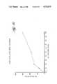
- Example 7The effect of applying successive coatings of a silicon oxidezirconium oxide mixture on S-type glass is graphically shown in Example 7 wherein significant improvement in flex life is obtained with, for instance, five coats and the flex life with ten coats is nearly 150 cycles to fail. This compares with 108 cycles for ceramic cloth and only 9 cycles to fail for heat cleaned S-type glass cloth having no finish. Similar flex life improvements are also realized with successive coatings of catalytic oxides. For instance, ten successive coatings of a vanadium oxide-titanium oxide mixture on heat cleaned S-type glass has given a flex life in the range of between about 110 and 170 cycles to fail, depending upon the method of cure, and even higher flex life can be obtained by the addition of further coatings.
- a very suitable filter bag clothcan be achieved, in accordance with another feature of this invention, by applying and curing, as described herein, at least one initial base coat of a relatively dilute solution of an alkoxide precursor of one or more refractory oxides, such as oxides of zirconium, titanium, and aluminum.
- Particularly suitable coatingshave been made by successively applying a base coat of a silicon oxidezirconium oxide mixture in a Si:Zr atomic ratio of between about 1:3 to 3:1, most preferably about 1:1, on S-type glass, to serve as a protective undercoat and also as a high surface area backbone, and then applying one or more catalytically active topcoats, such as a vanadium oxidetitanium oxide mixture to endow the cloth with catalytic properties.
- a base coat of a silicon oxidezirconium oxide mixture in a Si:Zr atomic ratio of between about 1:3 to 3:1, most preferably about 1:1, on S-type glassto serve as a protective undercoat and also as a high surface area backbone
- one or more catalytically active topcoatssuch as a vanadium oxidetitanium oxide mixture to endow the cloth with catalytic properties.
- the catalytically active coated fabric of this inventionis very suitable for use in filter installations, such as bag filters, for treatment of flue gases to simultaneously remove particulates and noxious gases such as SO 2 and NO x .
- the catalytically active fabricis ideally suited to installations wherein NO x is reduced by selective catalytic reduction (SCR).
- SCRselective catalytic reduction
- Selective catalytic reductioninvolves the reduction of nitrogen oxides by ammonia in the presence of a catalyst by the reactions:
- the ammoniawill be injected into the hot-particulate and NO x -laden flue gas, and the resulting gas mixture passed through the catalytically active filter bags, preferably at a temperature in the range of between about 300° C. and 400° C.
- the particulateswill be trapped in the filter bags, and the NO x catalytically reduced by the ammonia as it passes through the catalytically active fabric.
- the amount of ammonia requireddepends upon the NO x content of the flue gas as well as the NO x reduction efficiency of the particular catalyst being used. Literally thousands of catalysts have been tested for NO x control. See, for example, J. R. Kiovski, P. B. Koradia, and C. T. Lin, Ind. Eng.
- vanadium oxide based catalytic coatingsare highly suitable because of their high efficiency at relatively low temperatures, and their resistance to SO 2 poisoning.
- vanadium oxide-titanium mixturesto be even more catalytically active than pure vanadium oxide. Titanium oxide is believed to somehow increase the surface density of V ⁇ O groups. Since titanium oxides by itself is not a catalyst, it is believed to be a promoter for the vanadium oxide.
- the face velocities encountered in the selective catalytic reduction of NO x on catalytically active filter bagsis extremely high.
- the activity of filter bagsis normalized by the face velocity, which is the flow rate of gas divided by the cross-sectional area of the fabric.
- a typical face velocity for filter bagsis in the range of between about 1 and 3 feet per minute for reverse gas and shake-deflate designs, and between about 5 and 6 feet per minute for pulse jet designs.
- space velocityis the flow rate of gas or liquid flowing through the catalyst divided by the catalyst volume. Units of space velocity are generally reported in inverse hours, and a typical space velocity used in SCR processes are in the range of 3,000 to 10,000 hr. -1 .
- a fabricis 1 millimeter thick
- a typical face velocity for filter bags of 3 feet or 1 meter per minuteis equivalent to a space velocity of 60,000/hr. Therefore, a catalytic filter bag operating at normal face velocities must be from about 6 to 20 times more active than conventional catalysts which operate at 3,000 to 10,000/hour.
- the gas flow rate through a catalytically active filter bagmust be only 1/6 to 1/20 of the typical bag filter flow rates for a cloth of equivalent catalytic activity equal to existing SCR catalysts.
- the catalytic coating on the filter fabricpreferably will be capable of eliminating at least about 70 percent of the nitrogen oxides from the flue gas at face velocities of at least about 2 feet per minute.
- FIG. 1plots the specific area of coated fibers as a function of the alkoxide concentration in the coating solution for two different alkoxide mixtures, as described in greater detail in Example 2 below.
- FIG. 2illustrates the effect of the final cure temperature on the surface area of coated fibers, plotting surface area in square meters per gram as a function of the cure temperature. This is described in greater detail in Example 3 below.
- FIG. 3illustrates the catalytic activity of vanadium oxide-titanium oxide coated fibers (in terms of fraction of nitrogen oxides converted) as a function of the atomic ratio of vanadium to titanium in the coating solution, at three different cure temperatures. This figure is described in greater detail in Example 4 below.
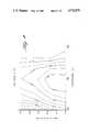
- FIG. 4illustrates the fraction of nitrogen oxides converted as a function of the face velocity of the flue gas and flue gas or conversion temperature for a glass cloth coated in accordance with the invention from a coating solution containing vanadyl and butylate and titanium i-propoxide in a molar ratio of 25:75. This is described in greater detail in Examples 4 and 6.
- FIG. 5illustrates the fraction of nitrogen oxide converted as a function of the face velocity and temperature of the flue gas when passed through a glass cloth having a V/Ti coating on a Si/Zr undercoating as described in further detail in Example 5.
- FIG. 6illustrates the fraction of nitrogen oxides converted as a function of face velocity and temperature of a flue gas when passed through a glass cloth coated in accordance with the invention and coated first in a microwave oven and subsequently in a conventional thermal oven, as described in greater detail in Example 6.
- FIG. 7illustrates the fraction of nitrogen oxides converted as a function of a face velocity and temperature of a flue gas when passed through a glass cloth coated first in a microwave oven only, as described in greater detail in Example 6.
- FIG. 8illustrates the flex life of glass cloth coated with a silicon oxide-zirconium oxide coatings in terms of the number of cycles to fail as a function of the number of coat and cure cycles utilized, as described in greater detail in Example 7.
- the highly porous, catalytically active coated fibrous substrate of the inventionis especially effective as a woven fabric for making catalytic bags for bag filter installations utilized for the simultaneous removal of particulates and noxious compounds from combustion flue gases.
- the inventionwill, therefore, be described in detail on the following examples with respect to features of this embodiment, in particular with respect to the catalytic reduction and removal of NO x , it being understood, however, that the invention is not limited thereto.
- An alkoxide solutionwas prepared by dissolving 52.08 g of silicon tetraethoxide (0.25 moles of Si(OC 2 H 5 ) 4 ) and 81.89 grams of zirconium tetrapropoxide (0.25 moles of Zr(OC 3 H 7 ) 4 ) in dry diacetone alcohol to make one liter of coating solution.
- the diacetone alcoholwas dried by immersing molecular sieve (Linde 5A) in it overnight, and removing the sieve by filtration prior to use.
- An alkoxide solutionwas prepared by dissolving 31.25 g of silicon tetraethoxide (0.15 moles) and 49.13 g of zirconium tetrapropoxide (0.15 moles) in dry diacetone alcohol to make one liter. This solution is a less concentrated coating solution than the solution used in Sample A. Heat cleaned E-glass fabric was coated with this solution and cured by the same procedure used in Sample A. The apparent surface area of this sample was 1.3 M 2 /g.
- An alkoxide solutionwas prepared by dissolving 142.1 g of titanium i-propoxide (0.5 moles of Ti(OC 3 H 7 ) 4 ) in dry diacetone alcohol to make one liter of coating solution. Heat cleaned S-type glass fabric was coated and cured by the same procedure used in Sample A. The apparent surface area of this sample was 0.5 M 2 /g.
- An alkoxide solutionwas prepared by dissolving 83.3 g of silicon tetraethoxide (0.4 moles) in 4 liters of diacetone alcohol. Since silicon tetraethoxide does not hydrolyze readily, the diacetone alcohol need not be dried. To catalyze the hydrolysis of silicon tetraethoxide after application to the glass, 5 ml. of concentrated nitric acid (HNO 3 ) was first dissolved in the diacetone alcohol before addition of alkoxide. Twenty yards of fabric 13 in. wide was dip-coated in this solution at a belt speed of 9 ft/min. and a dwell time of 5 seconds. The fabric was air dried for 15 minutes and then was cured at 350° C. by pulling the fabric through a 12 foot oven at 1.5 ft/min.
- HNO 3concentrated nitric acid
- the resultant BET apparent surface area of each samplewas measured, and plotted in FIG. 1 as a function of the total molar concentration of each respective coating solution. It is apparent from FIG. 1 that coatings formed from the Si/Zr alkoxide solutions at a given total molar concentration have a significantly higher BET apparent surface area as compared to coatings formed from V/Ti alkoxide solutions of like concentration. In both instances significant area increases occur above 0.10 M concentration.
- the clothwas dip coated in the coating solution dried in air for approximately 60 minutes and cured in an oven at 375° C. for about 4 hours.
- the catalytic activity of the clothswere tested using a laboratory reactor.
- a simulated flue gas mixtureconsisting of the following composition was used: 78% nitrogen, 6% oxygen, 16% carbon dioxide, 950 ppm nitric oxide. Ammonia was also present in the gas in an amount of 990 ppm.
- the simulated flue gas plus ammoniawas passed through a single thickness of coated cloth.
- concentration of nitric oxide in the flue gas after passing through the catalytic clothwas measured by a chemiluminescent analyzer.
- the activity of the clothwas measured at different temperatures and different face velocities of gas through the cloth.
- FIG. 3graphically illustrates the effect of the vanadium to titanium atomic ratio on the coated cloth on the fractional conversion of nitric oxides in the flue gas at a given face velocity of 2 feet per minute at conversion (flue gas) temperature of 300° C., 350° C., and 400° C. From this, it can be seen that optimum nitrogen oxide conversion occurs in the range of between about 40 and 60 percent vanadium.
- FIG. 4plots fractional conversion of nitrogen oxides in the flue gas for cloth Sample B as a function of the face velocity of flue gas through the sample and the temperature of the conversion.
- FIG. 4contains contour lines of constant catalytic activity, for example, the line labelled "0.50" denotes those conditions of face velocity and temperature where Sample C will convert half of the incoming nitrogen oxides. From this figure, it is apparent maximum nitrogen oxide conversion occurs at a conversion temperature of about 350° C.
- This exampledemonstrates the increase in catalytic activity achieved by applying an undercoating of a highly porous high refractory oxide coating before applying the porous catalyst coating.
- Heat cleaned S-type glass clothwas dip coated in a one liter solution containing 0.15 moles of silicon tetraethoxide and 0.15 moles of zirconium tetrapropoxide in diacetone alcohol. The cloth was air dried one hour, and cured at 375° C. for four hours. The cloth was then dip coated in a one liter solution containing 0.125 moles of vanadyl n-butylate and 0.375 moles of titanium i-propoxide in diacetone alcohol. The cloth was again air dried for one hour, and cured at 375° C. for four hours.
- the catalytic activity of the thus-coated clothwas tested using a reactor with a simulated flue gas mixture substantially in the same manner as described in Example 4, and the resulting activity is plotted on FIG. 5 as contour lines of constant catalytic activity, the values representing the fraction of NO converted. It is readily apparent by comparison of FIG. 5 against FIG. 4 that a substantial increase in catalytic activity has been obtained as compared to glass cloth coated with a 25% V/Ti oxide layer without the Si/Zr oxide undercoating.
- Sample Awas cured by heating at a 60% power level in a 700 watt microwave oven for 10 minutes and it was subsequently further cured in a conventional thermal oven at 375° C. for four hours.
- the catalytic activity of Sample Ais shown on FIG. 6.
- Sample Bwas cured by heating at a 60% power level in a 700 watt microwave oven for 10 minutes.
- the catalyst activity of this sampleis shown in FIG. 7.
- Sample Cafter drying, was cured in a conventional thermal oven at 375° C. for four hours, without any microwave cure.
- the catalytic activity of Sample Cis shown in FIG. 4.
- FIGS. 4, 6, and 7A comparison of FIGS. 4, 6, and 7 demonstrates that a combination of microwave and thermal cure results in a significantly increased catalytic activity for catalyst cloth as compared to either a microwave cure alone or a thermal cure alone.
- the flexibility and resistance to self-abrasion of glass cloth in the fill directionis tested by the MIT flex test in accordance with ASTM Test No. D 2176, using a 4 pound load and No. 8 spring. This is a standard test in which the sample is successively folded under controlled conditions until a tear occurs, and is designed to simulate the flexing that filter bags experience during the cleaning cycle. Tested under these conditions, heat cleaned S-type glass cloth, with no finish, failed after only 9 cycles.
- a coating solutionwas prepared by dissolving 114.5 grams of vanadyl-n-butylate (0.4 moles of VO(OC 4 H 9 ) 3 ) and 170.6 grams of titanium i-propoxide (0.6 moles Ti(OC 3 H 7 ) 4 ) in dry diacetone alcohol to make one liter of solution.
- the diacetone alcoholwas dried by immersing molecular sieve (Linde 5A) in it overnight, and removing the sieve by filtration prior to use.
- a 12 inch by 12 inch swatch of heat cleaned S-type glass cloth(33 oz/yd 2 ) was immersed in the solution for 10 seconds, removed, and allowed to air dry for 10 minutes.
- the fabricwas cured by heating it in a 700 watt microwave oven for 10 minutes, followed by heating the cloth in a conventional oven at 375° C. for four hours.
- a coating solutionwas prepared by dissolving 11.4 grams of vanadyl-n-butylate (0.04 moles of VO(OC 4 H 9 ) 3 ) and 17.1 grams of titanium (IV) i-propoxide (0.06 moles Ti(O(C 3 H 7 ) 4 ) in dry diacetone alcohol to make one liter of solution.
- the diacetone alcoholwas dried by immersing molecular sieve (Linde 5A) in it overnight, and removing the sieve by filtration prior to use.
- a 12 inch by 12 inch swatch of heat cleaned S-type glass cloth(33 oz/yd 2 ) was immersed in the solution for 10 seconds, removed, and allowed to air dry for 10 minutes.
- the fabricwas cured by heating it in a 700 watt microwave oven for 10 minutes.
- the coat-cure procedurewas repeated 20 times, so that thin layers of coating were deposited in succession.
- the fabricwas cured in a conventional oven for four hours at 375° C.
- Sample 3was a test of heat cleaned S-type glass cloth with no coating.
- a silicon oxide-titanium oxide mixture precursor solutionwas prepared by dissolving 10.4 grams of silicon tetraethoxide (0.05 moles of Si(OC 2 H 5 ) 4 ) and 16.4 grams of zirconium tetrapropoxide (0.05 moles of Zr(OC 3 H 7 ) 4 ) in dry diacetone alcohol to make one liter of solution.
- a vanadium oxide-titanium oxide mixture precursor solutionconsisting of 114.5 grams of vanadyl-n-butylate (0.4 moles of VO(OC 4 H 9 ) 3 ) and 170.6 grams of titanium (IV) i-propoxide (0.6 moles Ti(O(C 3 H 7 ) 4 ) in dry diacetone alcohol to make one liter of solution was prepared.
- a 12 inch by 12 inch swatch of heat cleaned S-type glass cloth(33 oz/yd 2 ) was immersed in the SiO 2 /ZrO 2 precursor solution for 10 seconds, removed, and allowed to air dry for 10 minutes.
- the fabricwas cured by heating it in a 700 watt microwave oven for 10 minutes. This procedure was repeated 5 times in order to build thin layers of a high surface area, abrasion resistant coating.
- the swatch of S-clothwas then immersed in the vanadium oxide-titanium oxide mixture precursor solution for 10 seconds, removed, and allowed to air dry for 10 minutes.
- the fabricwas cured by heating it in a 700 watt microwave oven for 10 minutes, followed by heating the cloth in a conventional oven at 375° C. for four hours.
- Sample 5is identical to Sample 2 except that a commercially available ceramic cloth was used as the support in place of S-type glass cloth.
- the NO x reduction capability of the fabric samples in a bag filter applicationwere evaluated under carefully controlled conditions that accurately simulated the actual flue gas composition that would be encountered.
- Fabric samples of about 0.5 ft 2 in sizewere housed in an oven which kept the samples at 650° ⁇ 25° F. Flue gas was drawn through the filter sample at a face velocity of 2.0 ft/min. After the filter, the flow was split with about 10 scfh going to a sample conditioner and flue gas analyzers, and the balance of about 20 scfh going to a gas pump and dry gas meter for control of the total flow.
- ammoniawas injected into the system well upstream of the sample point to insure that the ammonia was sufficiently mixed in the flue gas stream prior to sampling with a slipstream sampler.
- the ammoniawas set to the same concentration as the measured NO x level at the start of the test, and the NH 3 /NO x ratio was maintained at that level to within about ⁇ 10 percent throughout the tests.
- the flue gas for the testwas produced in a 550,000 btu/hr pulvarized coal fired particulate test combuster, which was specifically designed to generate particulate matter representative of large scale pulvarized coal-fired boilers.
- the average coal feed ratewas 73.8 lb/hr, and the range of combustion flue gas composition over the period of tests, measured just after the combustor, was as follows:
- NO x concentration in the gas downstream of the filterwas measured. NO x was also measured prior to starting the ammonia injection and again at the end of the test, after the ammonia injection was shut off, in order to establish the baseline readings. In general, the NO x removal was in the range of between about 82 and 97% at face velocities of about 2 ft/min.; a face velocity of 2 would ordinarily be encountered in bag filter applications. There was no evidence of deterioration of the NO x removal with time except for Sample 5, which appeared to deteriorate somewhat during the first hour of testing. However, after the first hour, the removal appeared to steady out and no further deterioration was evident. The results of the specific test samples is reported on the following table.
Landscapes
- Chemical & Material Sciences (AREA)
- Engineering & Computer Science (AREA)
- Chemical Kinetics & Catalysis (AREA)
- Materials Engineering (AREA)
- Organic Chemistry (AREA)
- Environmental & Geological Engineering (AREA)
- Health & Medical Sciences (AREA)
- Biomedical Technology (AREA)
- Analytical Chemistry (AREA)
- General Chemical & Material Sciences (AREA)
- Oil, Petroleum & Natural Gas (AREA)
- Catalysts (AREA)
- Exhaust Gas Treatment By Means Of Catalyst (AREA)
Abstract
Description
M(OR).sub.n +H.sub.2 O→M(OR).sub.n-1 OH+ROH (hydrolysis)
M(OR).sub.x (OH).sub.y +H.sub.2 O→M(OR).sub.x-1 (OH).sub.y+1 +ROH (hydrolysis)
M(OR).sub.x (OH).sub.y +M'(OR).sub.w (OH).sub.z →M(OR).sub.x (OH).sub.y-1 --O--M'(OR).sub.w (OH).sub.z-1 +H.sub.2 O (condensation)
6 NO+4 NH.sub.3 →5 N.sub.2 +6 H.sub.2 O
6 NO.sub.2 +8 NH.sub.3 →7 N.sub.2 +12 H.sub.2 O
NO+NH.sub.3 +V═O→V--OH+N.sub.2 +H.sub.2 O
4 VOH+O.sub.2 →4 V═O+2 H.sub.2 O
______________________________________ Vanadyl titanium n-butylate i-propoxide Sample (moles/liter) (moles/liter) ______________________________________ A 0.10 0.90 B 0.20 0.80 C 0.25 0.75 D 0.30 0.70 E 0.40 0.60 F 0.50 0.50 G 0.60 0.40 H 0.70 0.30 I 0.80 0.20 J 0.90 0.10 ______________________________________
______________________________________ Cycles to Sample Failure ______________________________________ 0.05 M Ti alkoxide solution 11 0.1 M Ti alkoxide solution 10 0.2 MTi alkoxide solution 6 0.3 M Ti alkoxide solution 10 0.4 M Ti alkoxide solution 5 0.5 M Ti alkoxide solution 5 0.05 M Zr alkoxide solution 29 0.1 M Zr alkoxide solution 44 0.2 M Zr alkoxide solution 39 0.3 M Zr alkoxide solution 19 0.4 M Zr alkoxide solution 8 0.5 M Zr alkoxide solution 12 0.3 M 50% Si/Zr alkoxide solution 32 0.5 M 25% V/Ti alkoxide solution 37 0.5 M 25% V/Ti on 0.3M 50% Si/Zr 28 ______________________________________
______________________________________ Component Concentration ______________________________________ Oxygen 4.26-5.0% by volume Carbon Dioxide 14.9-15.9% by volume Sulfur Dioxide 232-291 ppm Nitrogen Oxides 899-944 ppm ______________________________________
______________________________________ Approximate Face Samples Velocity (ft/min) % NO.sub.x Removal ______________________________________ 1 2.0 82.0-91.3 2 0.6 98.2-99.3 2 2.0 97.0-97.3 2 2.9-3.1 90.9-94.5 3 2.0 3.7-4.9 4 2.0 86.1-91.4 5 2.0 90.7-94.9 ______________________________________
Claims (15)
Priority Applications (1)
| Application Number | Priority Date | Filing Date | Title |
|---|---|---|---|
| US06/796,137US4732879A (en) | 1985-11-08 | 1985-11-08 | Method for applying porous, metal oxide coatings to relatively nonporous fibrous substrates |
Applications Claiming Priority (1)
| Application Number | Priority Date | Filing Date | Title |
|---|---|---|---|
| US06/796,137US4732879A (en) | 1985-11-08 | 1985-11-08 | Method for applying porous, metal oxide coatings to relatively nonporous fibrous substrates |
Publications (1)
| Publication Number | Publication Date |
|---|---|
| US4732879Atrue US4732879A (en) | 1988-03-22 |
Family
ID=25167392
Family Applications (1)
| Application Number | Title | Priority Date | Filing Date |
|---|---|---|---|
| US06/796,137Expired - LifetimeUS4732879A (en) | 1985-11-08 | 1985-11-08 | Method for applying porous, metal oxide coatings to relatively nonporous fibrous substrates |
Country Status (1)
| Country | Link |
|---|---|
| US (1) | US4732879A (en) |
Cited By (64)
| Publication number | Priority date | Publication date | Assignee | Title |
|---|---|---|---|---|
| US4911781A (en)* | 1987-05-05 | 1990-03-27 | The Standard Oil Company | VLS Fiber growth process |
| US4919905A (en)* | 1985-09-30 | 1990-04-24 | Mitsubishi Jukogyo Kabushiki Kaisha | Process for the systematic treatment of exhaust gases |
| EP0376025A1 (en)* | 1988-12-14 | 1990-07-04 | Degussa Aktiengesellschaft | Process for the reduction of nitrogen oxides in exhaust gases |
| US4957725A (en)* | 1988-07-05 | 1990-09-18 | The Johns Hopkins University | Vanadium dioxide formed by the sol-gel process |
| US4970097A (en)* | 1989-03-16 | 1990-11-13 | Owens-Corning Fiberglas Corporation | Method for forming abrasion resistant coating on fibrous glass substrate |
| EP0398752A1 (en)* | 1989-05-19 | 1990-11-22 | Babcock-Hitachi Kabushiki Kaisha | Catalyst for reducing nitrogen oxides |
| US5112676A (en)* | 1987-09-29 | 1992-05-12 | Centre National De La Recherche Scientifique 'cnrs | Method for the preparation of metallic oxide coatings |
| FR2673938A1 (en)* | 1991-03-13 | 1992-09-18 | Northrop Corp | Fibre/ceramic matrix composite and process for reinforcing this composite |
| US5210062A (en)* | 1991-08-26 | 1993-05-11 | Ford Motor Company | Aluminum oxide catalyst supports from alumina sols |
| US5227199A (en)* | 1992-01-14 | 1993-07-13 | General Atomics | Processes for applying metal oxide coatings from a liquid phase onto multifilament refractory fiber tows |
| US5316695A (en)* | 1989-08-10 | 1994-05-31 | Virginia Tech Intellectual Properties, Inc. | Use of polymeric catalyst in synthesis of sol-gel derived ceramic materials |
| WO1996018885A1 (en)* | 1994-12-16 | 1996-06-20 | Mine Safety Appliances Company | Microminiature combustible gas sensor and method of fabricating a microminiature combustible gas sensor |
| US5567394A (en)* | 1988-07-25 | 1996-10-22 | The Babcock & Wilcox Company | SOx , NOx , and particulate removal system |
| US5620669A (en)* | 1995-08-15 | 1997-04-15 | W. L. Gore & Associates, Inc. | Catalytic filter material and method of making same |
| US5683589A (en)* | 1995-03-13 | 1997-11-04 | University Of Western Ontario | Photocatalytic reactor |
| US5705444A (en)* | 1996-05-06 | 1998-01-06 | Minnesota Mining & Manufacturing Company | Filter material of ceramic oxide fibers and vermiculite particles |
| US6162759A (en)* | 1998-02-13 | 2000-12-19 | Sumitomo Chemical Company, Ltd. | Method for producing a catalyst component-carrying titania fiber |
| WO2000076660A1 (en)* | 1999-06-15 | 2000-12-21 | Ppg Industries Ohio, Inc. | Fiber glass carrier having increased surface area and photo-active matrices formed therefrom |
| US6214072B1 (en) | 1998-04-17 | 2001-04-10 | Menardi Mikropul, Llc | Ceramic coated filter medium and internal support |
| US6261449B1 (en) | 1999-03-30 | 2001-07-17 | Ultra-Jun Technologies, Inc. | Fluid purification system |
| US6331351B1 (en) | 1999-09-22 | 2001-12-18 | Gore Enterprise Holdings, Inc. | Chemically active filter material |
| US6541416B2 (en)* | 2000-06-13 | 2003-04-01 | Ube Industries, Ltd. | Silica-group composite oxide fiber and process for the production thereof |
| US6592991B1 (en)* | 1997-09-05 | 2003-07-15 | MAX-PLANCK-Gesellschaft zur Förderung der Wissenschaften e.V. | Block of copolymer phases as templates for structured organic-inorganic hybrid materials |
| EP1346765A4 (en)* | 2000-12-07 | 2004-04-07 | Sun Plastics Co Ltd | Material for capturing chemical substance and method for producing the same, and chemical substance-capturing tube |
| US20040074391A1 (en)* | 2002-10-16 | 2004-04-22 | Vincent Durante | Filter system |
| US20040079060A1 (en)* | 2002-10-28 | 2004-04-29 | Alward Gordon S. | Ceramic exhaust filter |
| US20040224594A1 (en)* | 2003-04-18 | 2004-11-11 | Choi Wai Ming | Low density nonwoven glass fiber web |
| US20050202241A1 (en)* | 2004-03-10 | 2005-09-15 | Jian-Ku Shang | High surface area ceramic coated fibers |
| US20050221087A1 (en)* | 2004-02-13 | 2005-10-06 | James Economy | Nanoporous chelating fibers |
| WO2005113126A1 (en)* | 2004-04-28 | 2005-12-01 | Geo2 Technologies, Inc. | Nonwoven composites and related products and methods |
| US20060000785A1 (en)* | 2003-12-03 | 2006-01-05 | Gregory Moller | Reactive filtration |
| US20060120937A1 (en)* | 2002-10-28 | 2006-06-08 | Bilal Zuberi | Multi-functional substantially fibrous mullite filtration substates and devices |
| US20060147677A1 (en)* | 2003-07-23 | 2006-07-06 | Canon Kabushiki Kaisha | Structured material and producing method thereof |
| US20060188416A1 (en)* | 2002-10-28 | 2006-08-24 | Alward Gordon S | Nonwoven composites and related products and methods |
| US20060201620A1 (en)* | 2000-11-14 | 2006-09-14 | Semiconductor Energy Laboratory Co., Ltd. | Light emitting device |
| US7211232B1 (en) | 2005-11-07 | 2007-05-01 | Geo2 Technologies, Inc. | Refractory exhaust filtering method and apparatus |
| US20070104621A1 (en)* | 2005-11-07 | 2007-05-10 | Bilal Zuberi | Catalytic Exhaust Device for Simplified Installation or Replacement |
| US20070151799A1 (en)* | 2005-12-30 | 2007-07-05 | Bilal Zuberi | Catalytic fibrous exhaust system and method for catalyzing an exhaust gas |
| US20070152364A1 (en)* | 2005-11-16 | 2007-07-05 | Bilal Zuberi | Process for extruding a porous substrate |
| US20070163958A1 (en)* | 2002-12-04 | 2007-07-19 | Blue Water Technologies, Inc. | Water Treatment Techniques |
| US20070187329A1 (en)* | 2002-12-04 | 2007-08-16 | Blue Water Technologies, Inc. | Water Treatment System and Method |
| US20070196652A1 (en)* | 2006-02-13 | 2007-08-23 | Ibiden Co., Ltd. | Inorganic fiber article |
| US20070207070A1 (en)* | 2006-03-03 | 2007-09-06 | Bilal Zuberi | Catalytic exhaust filter device |
| US20080072551A1 (en)* | 2002-10-28 | 2008-03-27 | Bilal Zuberi | Highly porous mullite particulate filter substrate |
| WO2008083310A1 (en)* | 2006-12-29 | 2008-07-10 | 3M Innovative Properties Company | Method of curing metal alkoxide-containing films |
| US20080261096A1 (en)* | 2000-06-29 | 2008-10-23 | Wolfgang Kollmann | Method For Producing Cathodes and Anodes for Electrochemical Systems, Metallised Material Used Therein, Method and Device For Production of Said Metallised Material |
| US7444805B2 (en) | 2005-12-30 | 2008-11-04 | Geo2 Technologies, Inc. | Substantially fibrous refractory device for cleaning a fluid |
| US7451849B1 (en) | 2005-11-07 | 2008-11-18 | Geo2 Technologies, Inc. | Substantially fibrous exhaust screening system for motor vehicles |
| US20090019770A1 (en)* | 2007-07-20 | 2009-01-22 | Pall Corporation | Catalytic element |
| US20090263303A1 (en)* | 2007-10-16 | 2009-10-22 | Aspen Products Group, Inc. | Purification Device and Method for Purifying a Fluid Stream |
| US20100068542A1 (en)* | 2006-12-29 | 2010-03-18 | 3M Innovative Properties Company | Method of making inorganic or inorganic/organic hybrid films |
| US7682578B2 (en) | 2005-11-07 | 2010-03-23 | Geo2 Technologies, Inc. | Device for catalytically reducing exhaust |
| US20100096339A1 (en)* | 2008-10-17 | 2010-04-22 | Rememberance Newcombe | Water Denitrification |
| US20100272933A1 (en)* | 2007-12-28 | 2010-10-28 | Mccormick Fred B | Flexible encapsulating film systems |
| US20110081502A1 (en)* | 2008-06-30 | 2011-04-07 | Bright Clark I | Method of making inorganic or inorganic/organic hybrid barrier films |
| WO2011148093A1 (en) | 2010-05-25 | 2011-12-01 | Saint-Gobain Quartz S.A.S | Method and device for purifying air |
| US20110311404A1 (en)* | 2010-06-16 | 2011-12-22 | Creedon Matthew J | Thermally Stable Inorganic Fibers For Exhaust Gas Treatment Device Insulating Mat |
| WO2017106730A1 (en) | 2015-12-17 | 2017-06-22 | W. L. Gore & Associates, Inc. | Catalytic filter material |
| WO2019099025A1 (en) | 2017-11-17 | 2019-05-23 | W. L. Gore & Associates, Inc. | Multilayer composite with catalytic mixed matrix membrane layer |
| US10608741B2 (en)* | 2018-05-29 | 2020-03-31 | 4S-Silversword Software And Services, Llc | Through the air link optical component |
| US10898855B2 (en) | 2017-04-26 | 2021-01-26 | Haldor Topsoe A/S | Method and system for the removal of noxious compounds from flue-gas using fabric filter bags with an SCR catalyst |
| US11007479B2 (en) | 2017-04-26 | 2021-05-18 | Haldor Topsoe A/S | Method and system for the removal of particulate matter and noxious compounds from flue-gas using a ceramic filter with an SCR catalyst |
| CN115957812A (en)* | 2021-10-09 | 2023-04-14 | 中国石油化工股份有限公司 | A modified hollow ceramic fiber and its preparation and application |
| US12362474B2 (en) | 2017-05-30 | 2025-07-15 | 4S-Silversword Software And Services, Llc | System and method for aligning RF phase in a distributed mobile platform ensemble utilizing a free space optical system to improve RF phase alignment |
Citations (22)
| Publication number | Priority date | Publication date | Assignee | Title |
|---|---|---|---|---|
| US3189563A (en)* | 1960-12-01 | 1965-06-15 | Engelhard Ind Inc | Open mesh glass fabric supported catalyst |
| US3323889A (en)* | 1963-04-16 | 1967-06-06 | Owens Illinois Inc | Method for increasing scratch resistance of a glass surface with a pyrolyzing treatment and a coating of an olefin polymer |
| US3562185A (en)* | 1967-01-04 | 1971-02-09 | Basf Ag | Oxidation catalysts containing vanadium pentoxide and titanium dioxide |
| US3873469A (en)* | 1972-04-12 | 1975-03-25 | Corning Glass Works | Support coatings for catalysts |
| US3929671A (en)* | 1970-07-30 | 1975-12-30 | Matsushita Electric Industrial Co Ltd | Auto exhaust control catalyst on silica cloth support |
| US3949109A (en)* | 1973-04-16 | 1976-04-06 | E. I. Du Pont De Nemours And Company | Support structures for fixed bed flow reactors |
| JPS5193922A (en)* | 1975-02-17 | 1976-08-18 | sio2 keisankabutsuhimakuno keiseihoho | |
| US4038214A (en)* | 1969-08-28 | 1977-07-26 | Mitsubishi Jukogyo Kabushiki Kaisha | Impregnated fibrous catalyst for treating exhaust gas of an internal combustion engine and process for making same |
| US4044102A (en)* | 1974-12-28 | 1977-08-23 | Kurashiki Boseki Kabushiki Kaisha | Method for treating exhaust gases |
| US4200609A (en)* | 1978-04-03 | 1980-04-29 | Mcdonnell Douglas Corporation | Ozone removal filter containing manganese dioxide and ceric oxide catalysts |
| US4220633A (en)* | 1979-04-30 | 1980-09-02 | The Babcock & Wilcox Company | Filter house and method for simultaneously removing NOx and particulate matter from a gas stream |
| JPS55134645A (en)* | 1979-04-05 | 1980-10-20 | Hitachi Zosen Corp | Basket shaped denitrificating catalyst |
| US4271210A (en)* | 1979-10-25 | 1981-06-02 | Westinghouse Electric Corp. | Method of forming transmissive, porous metal oxide optical layer of a vitreous substrate |
| US4303554A (en)* | 1979-06-22 | 1981-12-01 | Hitachi, Ltd. | Composition and process for producing transparent conductive film |
| US4309386A (en)* | 1979-04-30 | 1982-01-05 | The Babcock & Wilcox Company | Filter house having catalytic filter bags for simultaneously removing NOx and particulate matter from a gas stream |
| US4376804A (en)* | 1981-08-26 | 1983-03-15 | The Aerospace Corporation | Pyrolyzed pitch coatings for carbon fiber |
| US4376803A (en)* | 1981-08-26 | 1983-03-15 | The Aerospace Corporation | Carbon-reinforced metal-matrix composites |
| US4397666A (en)* | 1980-10-30 | 1983-08-09 | Central Glass Company Limited | Method of producing glass from metal alkoxide solution |
| US4400306A (en)* | 1982-06-28 | 1983-08-23 | The Standard Oil Company | Process for the preparation of fluidizable catalysts |
| US4405505A (en)* | 1980-04-02 | 1983-09-20 | Alusuisse Italia S.P.A. | Catalyst for the preparation of phthalic anhydride |
| JPS5973054A (en)* | 1982-10-15 | 1984-04-25 | Matsushita Electric Ind Co Ltd | Catalyst unit for exhaust gas purification |
| US4642302A (en)* | 1984-09-28 | 1987-02-10 | The Dow Chemical Company | Catalysts having alkoxide-modified supports and method of increasing the catalytic activity of a catalytic metal |
- 1985
- 1985-11-08USUS06/796,137patent/US4732879A/ennot_activeExpired - Lifetime
Patent Citations (22)
| Publication number | Priority date | Publication date | Assignee | Title |
|---|---|---|---|---|
| US3189563A (en)* | 1960-12-01 | 1965-06-15 | Engelhard Ind Inc | Open mesh glass fabric supported catalyst |
| US3323889A (en)* | 1963-04-16 | 1967-06-06 | Owens Illinois Inc | Method for increasing scratch resistance of a glass surface with a pyrolyzing treatment and a coating of an olefin polymer |
| US3562185A (en)* | 1967-01-04 | 1971-02-09 | Basf Ag | Oxidation catalysts containing vanadium pentoxide and titanium dioxide |
| US4038214A (en)* | 1969-08-28 | 1977-07-26 | Mitsubishi Jukogyo Kabushiki Kaisha | Impregnated fibrous catalyst for treating exhaust gas of an internal combustion engine and process for making same |
| US3929671A (en)* | 1970-07-30 | 1975-12-30 | Matsushita Electric Industrial Co Ltd | Auto exhaust control catalyst on silica cloth support |
| US3873469A (en)* | 1972-04-12 | 1975-03-25 | Corning Glass Works | Support coatings for catalysts |
| US3949109A (en)* | 1973-04-16 | 1976-04-06 | E. I. Du Pont De Nemours And Company | Support structures for fixed bed flow reactors |
| US4044102A (en)* | 1974-12-28 | 1977-08-23 | Kurashiki Boseki Kabushiki Kaisha | Method for treating exhaust gases |
| JPS5193922A (en)* | 1975-02-17 | 1976-08-18 | sio2 keisankabutsuhimakuno keiseihoho | |
| US4200609A (en)* | 1978-04-03 | 1980-04-29 | Mcdonnell Douglas Corporation | Ozone removal filter containing manganese dioxide and ceric oxide catalysts |
| JPS55134645A (en)* | 1979-04-05 | 1980-10-20 | Hitachi Zosen Corp | Basket shaped denitrificating catalyst |
| US4220633A (en)* | 1979-04-30 | 1980-09-02 | The Babcock & Wilcox Company | Filter house and method for simultaneously removing NOx and particulate matter from a gas stream |
| US4309386A (en)* | 1979-04-30 | 1982-01-05 | The Babcock & Wilcox Company | Filter house having catalytic filter bags for simultaneously removing NOx and particulate matter from a gas stream |
| US4303554A (en)* | 1979-06-22 | 1981-12-01 | Hitachi, Ltd. | Composition and process for producing transparent conductive film |
| US4271210A (en)* | 1979-10-25 | 1981-06-02 | Westinghouse Electric Corp. | Method of forming transmissive, porous metal oxide optical layer of a vitreous substrate |
| US4405505A (en)* | 1980-04-02 | 1983-09-20 | Alusuisse Italia S.P.A. | Catalyst for the preparation of phthalic anhydride |
| US4397666A (en)* | 1980-10-30 | 1983-08-09 | Central Glass Company Limited | Method of producing glass from metal alkoxide solution |
| US4376804A (en)* | 1981-08-26 | 1983-03-15 | The Aerospace Corporation | Pyrolyzed pitch coatings for carbon fiber |
| US4376803A (en)* | 1981-08-26 | 1983-03-15 | The Aerospace Corporation | Carbon-reinforced metal-matrix composites |
| US4400306A (en)* | 1982-06-28 | 1983-08-23 | The Standard Oil Company | Process for the preparation of fluidizable catalysts |
| JPS5973054A (en)* | 1982-10-15 | 1984-04-25 | Matsushita Electric Ind Co Ltd | Catalyst unit for exhaust gas purification |
| US4642302A (en)* | 1984-09-28 | 1987-02-10 | The Dow Chemical Company | Catalysts having alkoxide-modified supports and method of increasing the catalytic activity of a catalytic metal |
Non-Patent Citations (12)
| Title |
|---|
| Dislich et al., "Amorphous and Crystalline Dip Coatings Obtained from Organometallic Solutions: Procedures, Chemical Processes and Products", Thin Solid Films, vol. 77, No. 129 (1981). |
| Dislich et al., Amorphous and Crystalline Dip Coatings Obtained from Organometallic Solutions: Procedures, Chemical Processes and Products , Thin Solid Films, vol. 77, No. 129 (1981).* |
| Kiovski et al., "Evaluation of a New Zeolitic Catalyst for NOx Reduction with NH3", American Chemical Society, 1980. |
| Kiovski et al., Evaluation of a New Zeolitic Catalyst for NO x Reduction with NH 3 , American Chemical Society, 1980.* |
| Klein, "Sol-Gel Glass Technology--A Review", The Glass Industry, pp. 14-17, Jan. 1981. |
| Klein, Sol Gel Glass Technology A Review , The Glass Industry, pp. 14 17, Jan. 1981.* |
| Nicholas et al., "Carbon Monoxide Oxidation over a Platinum-Porous Fiber Glass Supported Catalyst", Ind. Eng. Chem. Prod. Res. Dev., vol. 15, No. 1, pp. 35-40 (1976). |
| Nicholas et al., "Oxidation of an Automobile Exhaust Gas Mixture by Fiber Catalysts", Ind. Eng. Chem., Prod. Res. Dev., vol. 15, No. 1, pp. 29-34 (1976). |
| Nicholas et al., Carbon Monoxide Oxidation over a Platinum Porous Fiber Glass Supported Catalyst , Ind. Eng. Chem. Prod. Res. Dev., vol. 15, No. 1, pp. 35 40 (1976).* |
| Nicholas et al., Oxidation of an Automobile Exhaust Gas Mixture by Fiber Catalysts , Ind. Eng. Chem., Prod. Res. Dev., vol. 15, No. 1, pp. 29 34 (1976).* |
| Schleppy et al., "Reduction of Nitric Oxide on Fiber Glass", Ind. Eng. Chem., Prod. Res. Dev., vol. 15, No. 3, pp. 172-176 (1976). |
| Schleppy et al., Reduction of Nitric Oxide on Fiber Glass , Ind. Eng. Chem., Prod. Res. Dev., vol. 15, No. 3, pp. 172 176 (1976).* |
Cited By (106)
| Publication number | Priority date | Publication date | Assignee | Title |
|---|---|---|---|---|
| US4919905A (en)* | 1985-09-30 | 1990-04-24 | Mitsubishi Jukogyo Kabushiki Kaisha | Process for the systematic treatment of exhaust gases |
| US4911781A (en)* | 1987-05-05 | 1990-03-27 | The Standard Oil Company | VLS Fiber growth process |
| US5112676A (en)* | 1987-09-29 | 1992-05-12 | Centre National De La Recherche Scientifique 'cnrs | Method for the preparation of metallic oxide coatings |
| US4957725A (en)* | 1988-07-05 | 1990-09-18 | The Johns Hopkins University | Vanadium dioxide formed by the sol-gel process |
| US5567394A (en)* | 1988-07-25 | 1996-10-22 | The Babcock & Wilcox Company | SOx , NOx , and particulate removal system |
| US5585081A (en)* | 1988-07-25 | 1996-12-17 | The Babcock & Wilcox Company | SOx, NOx and particulate removal system |
| EP0376025A1 (en)* | 1988-12-14 | 1990-07-04 | Degussa Aktiengesellschaft | Process for the reduction of nitrogen oxides in exhaust gases |
| US4970097A (en)* | 1989-03-16 | 1990-11-13 | Owens-Corning Fiberglas Corporation | Method for forming abrasion resistant coating on fibrous glass substrate |
| US5155083A (en)* | 1989-05-19 | 1992-10-13 | Babcock-Hitachi Kabushiki Kaisha | Catalyst for reducing nitrogen oxides and process for making the catalyst |
| EP0398752A1 (en)* | 1989-05-19 | 1990-11-22 | Babcock-Hitachi Kabushiki Kaisha | Catalyst for reducing nitrogen oxides |
| US5316695A (en)* | 1989-08-10 | 1994-05-31 | Virginia Tech Intellectual Properties, Inc. | Use of polymeric catalyst in synthesis of sol-gel derived ceramic materials |
| FR2673938A1 (en)* | 1991-03-13 | 1992-09-18 | Northrop Corp | Fibre/ceramic matrix composite and process for reinforcing this composite |
| US5210062A (en)* | 1991-08-26 | 1993-05-11 | Ford Motor Company | Aluminum oxide catalyst supports from alumina sols |
| US5227199A (en)* | 1992-01-14 | 1993-07-13 | General Atomics | Processes for applying metal oxide coatings from a liquid phase onto multifilament refractory fiber tows |
| WO1996018885A1 (en)* | 1994-12-16 | 1996-06-20 | Mine Safety Appliances Company | Microminiature combustible gas sensor and method of fabricating a microminiature combustible gas sensor |
| US5683589A (en)* | 1995-03-13 | 1997-11-04 | University Of Western Ontario | Photocatalytic reactor |
| US5843390A (en)* | 1995-08-15 | 1998-12-01 | W. L. Gore & Associates, Inc. | Method of using a catalytic filter |
| US5620669A (en)* | 1995-08-15 | 1997-04-15 | W. L. Gore & Associates, Inc. | Catalytic filter material and method of making same |
| US5705444A (en)* | 1996-05-06 | 1998-01-06 | Minnesota Mining & Manufacturing Company | Filter material of ceramic oxide fibers and vermiculite particles |
| US6592991B1 (en)* | 1997-09-05 | 2003-07-15 | MAX-PLANCK-Gesellschaft zur Förderung der Wissenschaften e.V. | Block of copolymer phases as templates for structured organic-inorganic hybrid materials |
| US6162759A (en)* | 1998-02-13 | 2000-12-19 | Sumitomo Chemical Company, Ltd. | Method for producing a catalyst component-carrying titania fiber |
| US6214072B1 (en) | 1998-04-17 | 2001-04-10 | Menardi Mikropul, Llc | Ceramic coated filter medium and internal support |
| US6274049B1 (en) | 1999-03-30 | 2001-08-14 | Ultra-Sun Technologies, Inc. | Method for purifying a fluid |
| US6330947B1 (en)* | 1999-03-30 | 2001-12-18 | Ultra-Sun Technologies, Inc | Method of manufacturing a filter |
| US6508367B2 (en)* | 1999-03-30 | 2003-01-21 | Robin Scott | Method of manufacturing a filter |
| US6524457B1 (en) | 1999-03-30 | 2003-02-25 | Robin Scott | Method of manufacturing a filter |
| US6261449B1 (en) | 1999-03-30 | 2001-07-17 | Ultra-Jun Technologies, Inc. | Fluid purification system |
| WO2000076660A1 (en)* | 1999-06-15 | 2000-12-21 | Ppg Industries Ohio, Inc. | Fiber glass carrier having increased surface area and photo-active matrices formed therefrom |
| US6331351B1 (en) | 1999-09-22 | 2001-12-18 | Gore Enterprise Holdings, Inc. | Chemically active filter material |
| US6541416B2 (en)* | 2000-06-13 | 2003-04-01 | Ube Industries, Ltd. | Silica-group composite oxide fiber and process for the production thereof |
| US20080261096A1 (en)* | 2000-06-29 | 2008-10-23 | Wolfgang Kollmann | Method For Producing Cathodes and Anodes for Electrochemical Systems, Metallised Material Used Therein, Method and Device For Production of Said Metallised Material |
| US20060201620A1 (en)* | 2000-11-14 | 2006-09-14 | Semiconductor Energy Laboratory Co., Ltd. | Light emitting device |
| US8557324B2 (en)* | 2000-11-14 | 2013-10-15 | Semiconductor Energy Laboratory Co., Ltd. | Light emitting device |
| EP1346765A4 (en)* | 2000-12-07 | 2004-04-07 | Sun Plastics Co Ltd | Material for capturing chemical substance and method for producing the same, and chemical substance-capturing tube |
| JPWO2002045848A1 (en)* | 2000-12-07 | 2004-04-08 | 津田 孝雄 | Chemical substance collector, method for producing the same, and chemical substance collection tube |
| JP4670112B2 (en)* | 2000-12-07 | 2011-04-13 | 孝雄 津田 | Chemical substance collector, production method thereof, and chemical substance collection tube |
| US20050148465A1 (en)* | 2002-10-16 | 2005-07-07 | Vincent Durante | Filter system |
| US20060116287A1 (en)* | 2002-10-16 | 2006-06-01 | Vincent Durante | Filter system |
| US20050152821A1 (en)* | 2002-10-16 | 2005-07-14 | Vincent Durante | Filter system |
| US7250387B2 (en) | 2002-10-16 | 2007-07-31 | Gore Enterprise Holdings, Inc. | Filter system |
| US20040074391A1 (en)* | 2002-10-16 | 2004-04-22 | Vincent Durante | Filter system |
| US20050100699A1 (en)* | 2002-10-16 | 2005-05-12 | Vincent Durante | Filter system |
| US20060188416A1 (en)* | 2002-10-28 | 2006-08-24 | Alward Gordon S | Nonwoven composites and related products and methods |
| US20040079060A1 (en)* | 2002-10-28 | 2004-04-29 | Alward Gordon S. | Ceramic exhaust filter |
| US7572311B2 (en) | 2002-10-28 | 2009-08-11 | Geo2 Technologies, Inc. | Highly porous mullite particulate filter substrate |
| US20060120937A1 (en)* | 2002-10-28 | 2006-06-08 | Bilal Zuberi | Multi-functional substantially fibrous mullite filtration substates and devices |
| US20090274602A1 (en)* | 2002-10-28 | 2009-11-05 | Alward Gordon S | Nonwoven Composites and Related Products and Methods |
| US7550117B2 (en) | 2002-10-28 | 2009-06-23 | Geo2 Technologies, Inc. | Nonwoven composites and related products and processes |
| US7574796B2 (en) | 2002-10-28 | 2009-08-18 | Geo2 Technologies, Inc. | Nonwoven composites and related products and methods |
| US7785544B2 (en) | 2002-10-28 | 2010-08-31 | GE02 Technologies, Inc. | Nonwoven composites and related products and methods |
| US6946013B2 (en) | 2002-10-28 | 2005-09-20 | Geo2 Technologies, Inc. | Ceramic exhaust filter |
| US20050042151A1 (en)* | 2002-10-28 | 2005-02-24 | Alward Gordon S. | Nonwoven composites and related products and processes |
| US20080112865A1 (en)* | 2002-10-28 | 2008-05-15 | Geo2 Technologies, Inc. | Nonwoven Composites and Related Products and Methods |
| US20080072551A1 (en)* | 2002-10-28 | 2008-03-27 | Bilal Zuberi | Highly porous mullite particulate filter substrate |
| US7582270B2 (en) | 2002-10-28 | 2009-09-01 | Geo2 Technologies, Inc. | Multi-functional substantially fibrous mullite filtration substrates and devices |
| US8071055B2 (en) | 2002-12-04 | 2011-12-06 | Blue Water Technologies, Inc. | Water treatment techniques |
| US20070187329A1 (en)* | 2002-12-04 | 2007-08-16 | Blue Water Technologies, Inc. | Water Treatment System and Method |
| US8080163B2 (en) | 2002-12-04 | 2011-12-20 | Blue Water Technologies, Inc. | Water treatment method |
| US20070163958A1 (en)* | 2002-12-04 | 2007-07-19 | Blue Water Technologies, Inc. | Water Treatment Techniques |
| US20040224594A1 (en)* | 2003-04-18 | 2004-11-11 | Choi Wai Ming | Low density nonwoven glass fiber web |
| US20060147677A1 (en)* | 2003-07-23 | 2006-07-06 | Canon Kabushiki Kaisha | Structured material and producing method thereof |
| US7781020B2 (en)* | 2003-07-23 | 2010-08-24 | Canon Kabushiki Kaisha | Structured material and producing method thereof |
| US7445721B2 (en)* | 2003-12-03 | 2008-11-04 | Idaho Research Foundation, Inc. | Reactive filtration |
| US20060000785A1 (en)* | 2003-12-03 | 2006-01-05 | Gregory Moller | Reactive filtration |
| US20050221087A1 (en)* | 2004-02-13 | 2005-10-06 | James Economy | Nanoporous chelating fibers |
| US8241706B2 (en) | 2004-03-10 | 2012-08-14 | The Board Of Trustees Of The University Of Illinois | High surface area ceramic coated fibers |
| US20050202241A1 (en)* | 2004-03-10 | 2005-09-15 | Jian-Ku Shang | High surface area ceramic coated fibers |
| WO2005113126A1 (en)* | 2004-04-28 | 2005-12-01 | Geo2 Technologies, Inc. | Nonwoven composites and related products and methods |
| US20070104621A1 (en)* | 2005-11-07 | 2007-05-10 | Bilal Zuberi | Catalytic Exhaust Device for Simplified Installation or Replacement |
| US7451849B1 (en) | 2005-11-07 | 2008-11-18 | Geo2 Technologies, Inc. | Substantially fibrous exhaust screening system for motor vehicles |
| US7211232B1 (en) | 2005-11-07 | 2007-05-01 | Geo2 Technologies, Inc. | Refractory exhaust filtering method and apparatus |
| US7682578B2 (en) | 2005-11-07 | 2010-03-23 | Geo2 Technologies, Inc. | Device for catalytically reducing exhaust |
| US7682577B2 (en) | 2005-11-07 | 2010-03-23 | Geo2 Technologies, Inc. | Catalytic exhaust device for simplified installation or replacement |
| US20070152364A1 (en)* | 2005-11-16 | 2007-07-05 | Bilal Zuberi | Process for extruding a porous substrate |
| US20070151799A1 (en)* | 2005-12-30 | 2007-07-05 | Bilal Zuberi | Catalytic fibrous exhaust system and method for catalyzing an exhaust gas |
| US7444805B2 (en) | 2005-12-30 | 2008-11-04 | Geo2 Technologies, Inc. | Substantially fibrous refractory device for cleaning a fluid |
| US7722828B2 (en) | 2005-12-30 | 2010-05-25 | Geo2 Technologies, Inc. | Catalytic fibrous exhaust system and method for catalyzing an exhaust gas |
| US7718252B2 (en)* | 2006-02-13 | 2010-05-18 | Ibiden Co., Ltd. | Inorganic fiber article |
| US20070196652A1 (en)* | 2006-02-13 | 2007-08-23 | Ibiden Co., Ltd. | Inorganic fiber article |
| US20070207070A1 (en)* | 2006-03-03 | 2007-09-06 | Bilal Zuberi | Catalytic exhaust filter device |
| US7563415B2 (en) | 2006-03-03 | 2009-07-21 | Geo2 Technologies, Inc | Catalytic exhaust filter device |
| CN101573471A (en)* | 2006-12-29 | 2009-11-04 | 3M创新有限公司 | Method of curing metal alkoxide-containing films |
| US8227040B2 (en) | 2006-12-29 | 2012-07-24 | 3M Innovative Properties Company | Method of curing metal alkoxide-containing films |
| US20100068382A1 (en)* | 2006-12-29 | 2010-03-18 | Strobel Mark A | Method of curing metal alkoxide-containing films |
| WO2008083310A1 (en)* | 2006-12-29 | 2008-07-10 | 3M Innovative Properties Company | Method of curing metal alkoxide-containing films |
| US20100068542A1 (en)* | 2006-12-29 | 2010-03-18 | 3M Innovative Properties Company | Method of making inorganic or inorganic/organic hybrid films |
| US7981274B2 (en)* | 2007-07-20 | 2011-07-19 | Pall Corporation | Catalytic element |
| US20090019770A1 (en)* | 2007-07-20 | 2009-01-22 | Pall Corporation | Catalytic element |
| US20090263303A1 (en)* | 2007-10-16 | 2009-10-22 | Aspen Products Group, Inc. | Purification Device and Method for Purifying a Fluid Stream |
| US20100272933A1 (en)* | 2007-12-28 | 2010-10-28 | Mccormick Fred B | Flexible encapsulating film systems |
| US8846169B2 (en) | 2007-12-28 | 2014-09-30 | 3M Innovative Properties Company | Flexible encapsulating film systems |
| US20110081502A1 (en)* | 2008-06-30 | 2011-04-07 | Bright Clark I | Method of making inorganic or inorganic/organic hybrid barrier films |
| US9481927B2 (en) | 2008-06-30 | 2016-11-01 | 3M Innovative Properties Company | Method of making inorganic or inorganic/organic hybrid barrier films |
| US9670082B2 (en) | 2008-10-17 | 2017-06-06 | Nexom (Us), Inc. | Water denitrification |
| US20100096339A1 (en)* | 2008-10-17 | 2010-04-22 | Rememberance Newcombe | Water Denitrification |
| US8741154B2 (en) | 2008-10-17 | 2014-06-03 | Remembrance Newcombe | Water denitrification |
| WO2011148093A1 (en) | 2010-05-25 | 2011-12-01 | Saint-Gobain Quartz S.A.S | Method and device for purifying air |
| US20110311404A1 (en)* | 2010-06-16 | 2011-12-22 | Creedon Matthew J | Thermally Stable Inorganic Fibers For Exhaust Gas Treatment Device Insulating Mat |
| WO2017106730A1 (en) | 2015-12-17 | 2017-06-22 | W. L. Gore & Associates, Inc. | Catalytic filter material |
| US10493388B2 (en) | 2015-12-17 | 2019-12-03 | W. L. Gore & Associates, Inc. | Catalytic filter material |
| US10898855B2 (en) | 2017-04-26 | 2021-01-26 | Haldor Topsoe A/S | Method and system for the removal of noxious compounds from flue-gas using fabric filter bags with an SCR catalyst |
| US11007479B2 (en) | 2017-04-26 | 2021-05-18 | Haldor Topsoe A/S | Method and system for the removal of particulate matter and noxious compounds from flue-gas using a ceramic filter with an SCR catalyst |
| US12362474B2 (en) | 2017-05-30 | 2025-07-15 | 4S-Silversword Software And Services, Llc | System and method for aligning RF phase in a distributed mobile platform ensemble utilizing a free space optical system to improve RF phase alignment |
| WO2019099025A1 (en) | 2017-11-17 | 2019-05-23 | W. L. Gore & Associates, Inc. | Multilayer composite with catalytic mixed matrix membrane layer |
| US10608741B2 (en)* | 2018-05-29 | 2020-03-31 | 4S-Silversword Software And Services, Llc | Through the air link optical component |
| CN115957812A (en)* | 2021-10-09 | 2023-04-14 | 中国石油化工股份有限公司 | A modified hollow ceramic fiber and its preparation and application |
Similar Documents
| Publication | Publication Date | Title |
|---|---|---|
| US4732879A (en) | Method for applying porous, metal oxide coatings to relatively nonporous fibrous substrates | |
| US3873469A (en) | Support coatings for catalysts | |
| CA1133456A (en) | Plate-shaped denitrating catalysts | |
| US3956185A (en) | Catalyst for exhaust gas purification | |
| US5741468A (en) | Exhaust gas cleaner and method for cleaning exhaust gas | |
| RU2400301C2 (en) | Catalyst carrier substrate coated by first coat composition that comprises fibrous material | |
| US5723403A (en) | Production process for catalysts on supports including a centrifuging step for the support after coating | |
| US5202299A (en) | Catalytic washcoat for treatment of diesel exhaust | |
| GB2257696A (en) | Method and apparatus for cleaning exhaust gas | |
| CN111013566B (en) | Novel rare earth modified aerogel denitration flue gas catalyst and preparation method thereof | |
| KR20120025444A (en) | Catalysts for lean burn engines | |
| JP2930990B2 (en) | Molecular sieves on supports-palladium-platinum catalysts | |
| US20110030354A1 (en) | Particulate combustion catalyst, particulate filter and exhaust gas purifying apparatus | |
| US3887740A (en) | Process for depositing oxide coatings | |
| WO2020025604A1 (en) | Vanadium-based selective catalytic reduction catalyst | |
| EP3963187B1 (en) | Multi-functional catalysts for the oxidation of no, the oxidation of nh3 and the selective catalytic reduction of nox | |
| KR100868958B1 (en) | Improved Selective Catalytic Reduction Catalyst Module for Nitrogen Oxide Removal Method and Stacked Catalyst Module for Selective Catalytic Reduction Reaction | |
| JP4298071B2 (en) | Exhaust gas purification material and method for producing the same | |
| JPH07100137B2 (en) | Exhaust gas adsorbent manufacturing method | |
| KR810000536B1 (en) | Plate-shaped denitrating catalysts | |
| JPH0438454B2 (en) | ||
| US3951866A (en) | Process for preparing catalysts | |
| CN114699845B (en) | Preparation method and application of denitration and dust removal integrated filter material | |
| JP2004041852A (en) | Catalyst carrier and catalyst body | |
| CN118543169B (en) | Metal fiber felt filter material with catalytic function and preparation method thereof |
Legal Events
| Date | Code | Title | Description |
|---|---|---|---|
| AS | Assignment | Owner name:WILMINGTON TRUST COMPANY, ONE RODNEY SQUARE NORTH, Free format text:SECURITY INTEREST;ASSIGNOR:OWENS-CORNING FIBERGLAS CORPORATION;REEL/FRAME:004652/0351 Effective date:19861103 Owner name:WADE, WILLIAM, J., ONE RODNEY SQUARE NORTH, WILMIN Free format text:SECURITY INTEREST;ASSIGNOR:OWENS-CORNING FIBERGLAS CORPORATION;REEL/FRAME:004652/0351 Effective date:19861103 Owner name:WILMINGTON TRUST COMPANY, DELAWARE Free format text:SECURITY INTEREST;ASSIGNOR:OWENS-CORNING FIBERGLAS CORPORATION;REEL/FRAME:004652/0351 Effective date:19861103 Owner name:WADE, WILLIAM, J., DELAWARE Free format text:SECURITY INTEREST;ASSIGNOR:OWENS-CORNING FIBERGLAS CORPORATION;REEL/FRAME:004652/0351 Effective date:19861103 | |
| AS | Assignment | Owner name:OWENS-CORNING FIBERGLAS CORPORATION, FIBERGLAS TOW Free format text:TERMINATION OF SECURITY AGREEMENT RECORDED NOV. 13, 1986. REEL 4652 FRAMES 351-420;ASSIGNORS:WILMINGTON TRUST COMPANY, A DE. BANKING CORPORATION;WADE, WILLIAM J. (TRUSTEES);REEL/FRAME:004903/0501 Effective date:19870730 Owner name:OWENS-CORNING FIBERGLAS CORPORATION, A CORP. OF DE Free format text:TERMINATION OF SECURITY AGREEMENT RECORDED NOV. 13, 1986. REEL 4652 FRAMES 351-420;ASSIGNORS:WILMINGTON TRUST COMPANY, A DE. BANKING CORPORATION;WADE, WILLIAM J. (TRUSTEES);REEL/FRAME:004903/0501 Effective date:19870730 | |
| AS | Assignment | Owner name:OWENS-CORNING FIBERGLAS CORPORATION, A CORP. OF DE Free format text:ASSIGNMENT OF ASSIGNORS INTEREST.;ASSIGNORS:KALINOWSKI, MARIE R.;NISHIOKA, GARY M.;REEL/FRAME:004767/0670 Effective date:19851101 | |
| STCF | Information on status: patent grant | Free format text:PATENTED CASE | |
| FPAY | Fee payment | Year of fee payment:4 | |
| AS | Assignment | Owner name:OWENS-CORNING FIBERGLAS TECHNOLOGY INC., ILLINOIS Free format text:ASSIGNMENT OF ASSIGNORS INTEREST.;ASSIGNOR:OWENS-CORNING FIBERGLAS CORPORATION, A CORP. OF DE;REEL/FRAME:006041/0175 Effective date:19911205 | |
| FEPP | Fee payment procedure | Free format text:PAYOR NUMBER ASSIGNED (ORIGINAL EVENT CODE: ASPN); ENTITY STATUS OF PATENT OWNER: LARGE ENTITY | |
| FPAY | Fee payment | Year of fee payment:8 | |
| AS | Assignment | Owner name:ADVANCED GLASSFIBER YARNS, LLC, SOUTH CAROLINA Free format text:ASSIGNMENT OF ASSIGNORS INTEREST;ASSIGNORS:OWENS-CORNING FIBERGLASS TECHNOLOGY, INC.;OWENS-CORNING;REEL/FRAME:009534/0670 Effective date:19980930 Owner name:FIRST UNION NATIONAL BANK, AS AGENT, NORTH CAROLIN Free format text:NOTICE OF GRANT OF SECURITY INTEREST IN PATENTS;ASSIGNOR:ADVANCED GLASSFIBER YARNS LLC;REEL/FRAME:009534/0209 Effective date:19980930 | |
| FPAY | Fee payment | Year of fee payment:12 | |
| FEPP | Fee payment procedure | Free format text:PAYOR NUMBER ASSIGNED (ORIGINAL EVENT CODE: ASPN); ENTITY STATUS OF PATENT OWNER: LARGE ENTITY Free format text:PAYER NUMBER DE-ASSIGNED (ORIGINAL EVENT CODE: RMPN); ENTITY STATUS OF PATENT OWNER: LARGE ENTITY | |
| AS | Assignment | Owner name:WACHOVIA BANK, NATIONAL ASSOCIATION, AS AGENT, GEO Free format text:SECURITY AGREEMENT;ASSIGNORS:ADVANCED GLASSFIBER YARNS LLC;AGY CAPITAL CORP.;REEL/FRAME:013746/0001 Effective date:20021211 | |
| AS | Assignment | Owner name:WACHOVIA BANK, NATIONAL ASSOCATION, GEORGIA Free format text:SECURITY AGREEMENT;ASSIGNORS:AGY HOLDING CORP.;AGY AKIEN LLC;AGY HUNTINGDON LLC;REEL/FRAME:015328/0741 Effective date:20040402 | |
| AS | Assignment | Owner name:CIT GROUP/BUSINESS CREDIT, INC., THE, NEW YORK Free format text:PATENT SECURITY AGREEMENT;ASSIGNORS:AGY HOLDING CORP.;AGY AIKEN LLC;AGY HUNTINGDON LLC;REEL/FRAME:015139/0631 Effective date:20040402 |