US4732247A - Triple cone synchronizer with servo action - Google Patents
Triple cone synchronizer with servo actionDownload PDFInfo
- Publication number
- US4732247A US4732247AUS07/005,719US571987AUS4732247AUS 4732247 AUS4732247 AUS 4732247AUS 571987 AUS571987 AUS 571987AUS 4732247 AUS4732247 AUS 4732247A
- Authority
- US
- United States
- Prior art keywords
- cone
- ring
- ratio gear
- synchronizer
- external
- Prior art date
- Legal status (The legal status is an assumption and is not a legal conclusion. Google has not performed a legal analysis and makes no representation as to the accuracy of the status listed.)
- Expired - Fee Related
Links
- 230000001154acute effectEffects0.000claimsabstractdescription9
- 230000000903blocking effectEffects0.000claimsdescription28
- 230000007935neutral effectEffects0.000claimsdescription4
- 230000008878couplingEffects0.000claims1
- 238000010168coupling processMethods0.000claims1
- 238000005859coupling reactionMethods0.000claims1
- 230000005540biological transmissionEffects0.000description4
- 230000013011matingEffects0.000description4
- 239000000463materialSubstances0.000description2
- 238000013459approachMethods0.000description1
- 230000000295complement effectEffects0.000description1
- 230000006835compressionEffects0.000description1
- 238000007906compressionMethods0.000description1
- 238000006073displacement reactionMethods0.000description1
- 230000009977dual effectEffects0.000description1
- 238000004519manufacturing processMethods0.000description1
- 239000002184metalSubstances0.000description1
Images


Classifications
- F—MECHANICAL ENGINEERING; LIGHTING; HEATING; WEAPONS; BLASTING
- F16—ENGINEERING ELEMENTS AND UNITS; GENERAL MEASURES FOR PRODUCING AND MAINTAINING EFFECTIVE FUNCTIONING OF MACHINES OR INSTALLATIONS; THERMAL INSULATION IN GENERAL
- F16D—COUPLINGS FOR TRANSMITTING ROTATION; CLUTCHES; BRAKES
- F16D23/00—Details of mechanically-actuated clutches not specific for one distinct type
- F16D23/02—Arrangements for synchronisation, also for power-operated clutches
- F16D23/04—Arrangements for synchronisation, also for power-operated clutches with an additional friction clutch
- F16D23/06—Arrangements for synchronisation, also for power-operated clutches with an additional friction clutch and a blocking mechanism preventing the engagement of the main clutch prior to synchronisation
- F16D2023/0656—Details of the tooth structure; Arrangements of teeth
- F—MECHANICAL ENGINEERING; LIGHTING; HEATING; WEAPONS; BLASTING
- F16—ENGINEERING ELEMENTS AND UNITS; GENERAL MEASURES FOR PRODUCING AND MAINTAINING EFFECTIVE FUNCTIONING OF MACHINES OR INSTALLATIONS; THERMAL INSULATION IN GENERAL
- F16D—COUPLINGS FOR TRANSMITTING ROTATION; CLUTCHES; BRAKES
- F16D23/00—Details of mechanically-actuated clutches not specific for one distinct type
- F16D23/02—Arrangements for synchronisation, also for power-operated clutches
- F16D23/04—Arrangements for synchronisation, also for power-operated clutches with an additional friction clutch
- F16D23/06—Arrangements for synchronisation, also for power-operated clutches with an additional friction clutch and a blocking mechanism preventing the engagement of the main clutch prior to synchronisation
- F16D2023/0681—Double cone synchromesh clutches
- F—MECHANICAL ENGINEERING; LIGHTING; HEATING; WEAPONS; BLASTING
- F16—ENGINEERING ELEMENTS AND UNITS; GENERAL MEASURES FOR PRODUCING AND MAINTAINING EFFECTIVE FUNCTIONING OF MACHINES OR INSTALLATIONS; THERMAL INSULATION IN GENERAL
- F16D—COUPLINGS FOR TRANSMITTING ROTATION; CLUTCHES; BRAKES
- F16D23/00—Details of mechanically-actuated clutches not specific for one distinct type
- F16D23/02—Arrangements for synchronisation, also for power-operated clutches
- F16D23/04—Arrangements for synchronisation, also for power-operated clutches with an additional friction clutch
- F16D23/06—Arrangements for synchronisation, also for power-operated clutches with an additional friction clutch and a blocking mechanism preventing the engagement of the main clutch prior to synchronisation
- F16D23/0612—Arrangements for synchronisation, also for power-operated clutches with an additional friction clutch and a blocking mechanism preventing the engagement of the main clutch prior to synchronisation the blocking mechanism comprising a radial pin in an axial slot with at least one branch
Definitions
- This inventionrelates to multiple cone-type strutless synchronizers for manual transmissions and more particularly to an improved triple cone blocker ring strutless synchronizer incorporating servo action.
- Strutless synchronizerssuch as disclosed in the U.S. Pat. No. 3,700,083 issued Oct. 29, 1972 to N. Ashikawa et al, are well known in the synchromesh transmission art.
- the '083 patentemploys an annular spring interposed between a sleeve, slidably mounted on a hub on a main shaft, and a blocker ring provided on the conical slidable surface of a speed ratio gear.
- the annular springis slidably mounted in a snug manner on the outer surface of three uniformly spaced axially extending lugs integrally formed as the blocking ring.
- the annular spring interposed between the sleeve and the blocker ring lugsis so arranged that upon movement of the sleeve, the annular spring is first pushed axially by certain of the sleeve internal uniformly spaced splines. This in turn causes the annular spring to axially push the blocker ring. The blocker ring is then seated on the gear cone which, having a relative rotational speed, generates a cone torque to index or clock the blocker ring to the desired blocking position. Once synchronization is complete, the annular spring is then compressed and deflected radially inward by the sleeve as the sleeve passes over the spring. As a result, the sleeve internal splines mesh with a driven gear journaled on the main shaft and thus rotation of the main shaft is transmitted to the driven gear.
- the U.S. Pat. No. 4,623,054 issued Nov. 18, 1986 to Barksdalediscloses a dual cone pin type synchronizing clutch having multiple conical friction elements for synchronizing the speeds of a shaft and a gear wheel before clutch engagement.
- the '054 patentincludes a cone element member rotatably supported on a gear wheel and free to rotate relative to a conical friction surface on the gear wheel.
- a hubis splined to the shaft and has external teeth engaged by internal teeth of the synchronizer clutch sleeve.
- the clutch sleevedefines blocking surfaces that contact mating blocking surfaces on a cone arm assembly.
- the cone arm assemblyis moved axially bringing the conical surface into contact with the mating friction surfaces on an intermediate cone member fixed to the gear wheel. This frictional engagement operates to synchronize the speeds of the gear wheel and the clutch hub before the sleeve is moved axially further into mechanical engagement with the clutching teeth on the gear wheel.
- the first cone surfaceis exteriorly formed on a ratio gear rotatably supported on a transmission shaft.
- the second cone surfaceis formed on the interior of an outer cone ring while the third cone surface is formed on the interior of a blocker ring.
- the first blocking surfaceis provided on the interior of the inner cone ring and is adapted to contact the ratio gear first cone surface.
- the second blocking surfaceis defined by the exterior of the inner cone ring and it is adapted to contact the second interior surface of the outer cone ring.
- the third blocking surfaceis defined by the exterior of the outer cone ring for and is adapted to contact the interior cone surface on the blocker ring.
- the outer cone ringhas a plurality of forwardly projecting drive tangs each of which engages in a window formed on a radial flange of the ratio gear.
- Each drive tangis symmetrical about its longitudinal centerline defining identical back-angled cam edges.
- a cam edge of each drive tangis operative to slidably engage an opposed matching angled side wall of its associated window upon an axial shifting force being applied to the synchronizer.
- the inner cone ringhas a plurality of rearwardly projecting locking fingers each of which engages in a hole formed in the hub radial flange.
- annular springis contacted by inclined surfaces of radial teeth formed on at least three equally spaced sleeve internal splines.
- the annular springis interposed between the sleeve and three raised lugs on the outer surface of the blocker ring.
- the annular springis arranged so that at the time of displacement of the sleeve, the spring is initially pushed axially by the sleeve teeth thereby pushing the blocker ring forwardly. This results in the blocker ring interior cone surface being brought into frictional engagement with the exterior blocking surface of the outer cone ring.
- the blocker ring interior cone surface and the outer cone ring exterior blocking surface frictional torqueworks against each tang back-angled cam edge providing a forwardly directed axial force component causing the outer cone ring to be drawn into tighter engagement with the ratio gear.
- Such engagementresults in an increase in the clamping force between both the remaining cone surfaces and their respective blocking surfaces thereby increasing the synchronizer torque capacity.
- the particular angle of the back angled cam edges chosen for the drive tangs and window side wallsis determined by balancing the degree of slope of the with the coefficient of friction of the particular type of material used in the manufacture of the friction pads or lining bonded to the blocking surfaces.
- FIG. 1is an axial longitudinal cross-sectional view of the synchronizing mechanism according to the present invention
- FIG. 2is an enlarged fragmentary view of a portion of FIG. 1 within the circle designated 2;
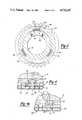
- FIG. 3is an enlarged fragmentary cross-sectional view taken substantially on the line 3--3 of FIG. 1;
- FIG. 4is a fragmentary cross-sectional view, with parts broken away, taken substantially on the line 4--4 of FIG. 3;
- FIG. 4Ais a view similar to FIG. 4 showing the outer cone ring rotated wherein its cam fingers inclined edges are in engagement with ratio gear complementary cam surfaces;
- FIG. 5is an enlarged cross-sectional view taken substantially on the line 5--5 of FIG. 1;
- FIG. 6is an exploded perspective view of the synchronizer mechanism shown in FIG. 1.
- FIG. 1a power transfer shaft 10 on which is rotatably supported a ratio gear 12 by means of needle bearings 14. Disposed on one side of the ratio gear 12 is a synchronizer assembly generally indicated at 16 operable to cause selective speed synchronization between shaft 10 and ratio gear 12.
- the synchronizer assembly 16is operated through a shift sleeve 20 which is connected by a yoke groove 22 to a conventional mechanical shift fork mechanism partially shown at 24.
- the synchronizer assembly 16includes a hub 26 fixedly connected to the shaft 10 through hub internal splines 28 engaging shaft external splines 30.
- a snap ring 32positions the hub 26 on the shaft 10 in cooperation with its annular shoulder 34.
- the sleeve 20is mounted on the hub 26 by means of hub external splines 36 (FIG. 1) engaging sleeve internal splines 38.
- the sleeve 20is axially slidable on the hub 26 by means of the shift mechanism 24.
- the synchronizer assembly 16is a triple cone type synchronizing clutch having a blocker ring 40.
- the blocker ringis provided with three raised lugs 42 equally spaced at 120 degree intervals around the ring 40.
- FIG. 5shows lug 42 nested within its associated hub notch 43.
- the hub external splines 36are interrupted at three uniformly spaced locations by notches 43 axially centered to receive associated blocker ring lugs 42 therein as indicated in FIG. 6.
- its lugs 42have their respective side faces 42' adapted to contact an opposed face of its associated notch.
- the assemblyprovides three cone surfaces and three mating friction blocking surfaces.
- the ratio gear 12provides a first external cone surface 44.
- a second internal cone surface 46is formed on the interior of outer cone ring 48.
- the blocker, ring 40 interior cone surfacedefines third internal cone surface 50.
- a first interior blocking surface 52is provided on the interior of inner cone ring 54 and is adapted to contact the ratio gear exterior cone surface 44.
- a second blocking surface 56is defined by the exterior of the inner cone ring 54 which is adapted to contact the outer cone ring interior cone surface 46.
- a third blocking surface 58is located on the exterior of the outer cone ring 48 and is adapted to contact the blocker ring interior cone surface 50. It will be noted that in the disclosed embodiment each of the three blocking surfaces 52, 56 and 58 is in the form of a friction pad or lining bonded or cemented to its associated metal cone ring providing effective frictional engagement.
- An example of one type of a friction lining that may be used with the present inventionis disclosed in U.S. Pat. No. 4,267,912 issued May 29, 1981 to Bauer et al., the disclosure of which is incorporated by reference herein.
- the outer cone ring 48has three rightwardly or forwardly projecting torque drive tangs 60 formed integral therewith and uniformly spaced on 120 degree centers. Each of the torque drive tangs 60 extends forwardly parallel to the main shaft principal axis and engages in an associated window 62 formed in splined flange 64 extending radially from the ratio gear as seen in FIG. 1.
- each drive tang 60is formed symmetrical about its longitudinal axis of symmetry which axis coincides with its associated window 62 axial centerline 66 when the synchronizer is in its neutral position.
- the drive tang 60defines a pair of back-angled cam edges 68 and 70.
- Each back-angled cam edge 68 and 70is shown diverging outwardly from the longitudinal centerline 66 at a predetermined acute angle "X" which in the disclosed embodiment defines an angle of 23 degrees.
- window 62is also formed symmetrical about its centerline 66 with its opposed side walls 72 and 74 each disposed at a predetermined matching acute angle "Y" (Fig. 4A) with centerline 66 equal to the angle "X".
- the window side wall 72is disposed in parallel spaced relation to its associated tang cam edge 68 and the window side wall 74 is disposed in parallel spaced relation to its associated tang cam edge 70 with the synchronizer in its neutral position of FIG. 4.
- the ratio gear 12has a toothed outer diameter 84 adapted to mesh with other gear members in a well-known manner.
- the ratio gear flange portion 64has a toothed or splined surface 86 which is coaxial and alignable with a toothed or splined surface 88 formed on the outer circumference of synchronizer blocker ring 40. Both toothed surfaces 86 and 88 are engageable by a toothed surface defined by the shift ring internal splines 38.
- the splines 38are in continual engagement with the external splines 36 formed on the hub 26.
- the inner cone ring 56is formed with three axially extending uniformly spaced locking fingers 90.
- the locking fingers 90extend to the left as viewed in FIG. 2, projecting into associated aligned circular openings 92 formed in hub 26.
- the synchronizer assembly 16includes an annular spring 94 mounted on blocker ring 40.
- the spring 94is formed with a predetermined internal diameter such that it is slidably received on the three lugs 42 in a snug press-fit manner.
- the function of the spring 94is generally set forth in U.S. Pat. No. 3,700,083 issued Oct. 24, 1972 to Askikawa et al entitled "Synchromesh Transmission Apparatus". As shown and described in the 3,700,083 patent projections in the form of radial teeth portions 96 (FIG. 2), are formed at the rightward end of three pair of the 120 degree spaced sleeve internal splines 38. of the sleeve 20.
- each pair of radial teeth portions 96contact the annular spring 44. At this point the running clearances between all the axially moving parts has been taken up. Next a detent load builds up as the annular spring 94 is compressed radially by the sleeve teeth 96. The radial compression of the annular spring 94 generates initial cone torque between the blocker ring interior cone surface 50 and the outer cone ring exterior blocking surface 58.
- angle "X"is 23 degrees other angles may be used depending upon various factors such as the type of material used for the friction pad or lining on the blocking surfaces 52, 56 and 58.
- the drive tang side edges 68 and 70 angle “X”may have a range of about 18 degrees to 28 degrees without departing from the scope of the invention.
- the window side walls 72 and 74will also be formed at a matching acute angle "Y" equal to the selected angle "X".
Landscapes
- Engineering & Computer Science (AREA)
- General Engineering & Computer Science (AREA)
- Mechanical Engineering (AREA)
- Mechanical Operated Clutches (AREA)
Abstract
Description
Claims (4)
Priority Applications (2)
| Application Number | Priority Date | Filing Date | Title |
|---|---|---|---|
| US07/005,719US4732247A (en) | 1987-01-21 | 1987-01-21 | Triple cone synchronizer with servo action |
| CA000552970ACA1324330C (en) | 1987-01-21 | 1987-11-27 | Triple cone synchronizer with servo action |
Applications Claiming Priority (1)
| Application Number | Priority Date | Filing Date | Title |
|---|---|---|---|
| US07/005,719US4732247A (en) | 1987-01-21 | 1987-01-21 | Triple cone synchronizer with servo action |
Publications (1)
| Publication Number | Publication Date |
|---|---|
| US4732247Atrue US4732247A (en) | 1988-03-22 |
Family
ID=21717364
Family Applications (1)
| Application Number | Title | Priority Date | Filing Date |
|---|---|---|---|
| US07/005,719Expired - Fee RelatedUS4732247A (en) | 1987-01-21 | 1987-01-21 | Triple cone synchronizer with servo action |
Country Status (2)
| Country | Link |
|---|---|
| US (1) | US4732247A (en) |
| CA (1) | CA1324330C (en) |
Cited By (59)
| Publication number | Priority date | Publication date | Assignee | Title |
|---|---|---|---|---|
| US4823631A (en)* | 1986-05-26 | 1989-04-25 | Mazda Motor Corp. | Transmission synchronizer |
| US4838399A (en)* | 1987-05-20 | 1989-06-13 | Toyota Jidosha Kabushiki Kaisha | Gear synchronizer for power transmission |
| US4842112A (en)* | 1987-05-09 | 1989-06-27 | Toyota Jidosha Kabushiki Kaisha | Gear synchronizer for power transmission |
| US4998445A (en)* | 1989-11-01 | 1991-03-12 | Tanaka Seimitu Kogyo Kabushiki Kaisha | Synchronizer ring |
| FR2663389A1 (en)* | 1990-06-15 | 1991-12-20 | Peugeot | Synchromesh |
| US5085303A (en)* | 1990-10-01 | 1992-02-04 | New Venture Gear, Inc. | Drag-free strut-type synchronizer |
| US5105927A (en)* | 1991-01-16 | 1992-04-21 | New Venture Gear, Inc. | Single cone servo action synchronizer |
| US5135087A (en)* | 1991-01-16 | 1992-08-04 | New Venture Gear, Inc. | Dual-cone synchronizer with servo action |
| US5343993A (en)* | 1991-04-10 | 1994-09-06 | Hoerbiger & Co. | Synchronizing device for transmission assemblies and having friction-coupled assemblies |
| US5507376A (en)* | 1993-12-02 | 1996-04-16 | Eaton Corporation | Synchronizer with self-energizing |
| US5560461A (en)* | 1995-02-24 | 1996-10-01 | Dana Corporation | Multiple cone synchronizer for vehicle transmission |
| US5615758A (en)* | 1994-09-30 | 1997-04-01 | Nels; Terry E. | Fabric arrangement and method for controlling fluid flow |
| EP0754874A3 (en)* | 1995-07-20 | 1997-05-02 | Kyowa Metal Works Co Ltd | Synchronizing apparatus for transmission |
| US5678670A (en)* | 1993-11-18 | 1997-10-21 | Volvo Lastvagnar Ab | Synchronizing device in a vehicle gearbox |
| US5713447A (en)* | 1995-08-11 | 1998-02-03 | Eaton Corporation | Synchronizer with self-energizing |
| USRE35796E (en)* | 1990-12-24 | 1998-05-19 | Eaton Corporation | Self-energizing synchronizer |
| US5788036A (en)* | 1995-10-30 | 1998-08-04 | Hoerbiger Antriebstechnik Gmbh | Synchronizing arrangement for a gear transmission |
| US5845754A (en)* | 1996-11-25 | 1998-12-08 | Borg-Warner Automotive, Inc. | Shift synchronizer for two speed transfer case and the like |
| EP0916864A1 (en)* | 1997-11-12 | 1999-05-19 | FIAT AUTO S.p.A. | A synchronizing unit for the gears of a motor vehicle transmission |
| US6016895A (en)* | 1997-04-30 | 2000-01-25 | Ina Walzlager Schaeffler Ohg | Synchronizing device |
| US6027422A (en)* | 1997-09-11 | 2000-02-22 | Tochigi Fuji Sangyo Kabushiki Kaisha | Switching synchronous apparatus for four wheel drive vehicle |
| US6065579A (en)* | 1994-09-30 | 2000-05-23 | Select Powertrain Technologies Corp. | Synchronizer blocker rings used in manual transmissions |
| EP1101965A3 (en)* | 1999-11-15 | 2002-06-19 | HOERBIGER Antriebstechnik GmbH | Multiple synchronizer assembly for motor vehicle gear box. |
| FR2821652A1 (en)* | 2001-03-02 | 2002-09-06 | Renault | FRICTION CONE COUPLING DEVICE FOR GEARBOXES |
| US6533091B1 (en)* | 1999-11-01 | 2003-03-18 | Honda Giken Kogyo Kabushiki Kaisha | Synchromesh unit for transmission |
| WO2004031602A1 (en)* | 2002-09-25 | 2004-04-15 | Ina-Schaeffler Kg | Arrangement of synchronisation rings |
| US20040099078A1 (en)* | 2001-01-31 | 2004-05-27 | O-Oka Corporation | Gear, method and device for manufacturing the same |
| US20050011720A1 (en)* | 2003-07-14 | 2005-01-20 | Adair Jeffrey W. | Friction material having oil localization slots |
| US20050016306A1 (en)* | 1999-12-17 | 2005-01-27 | Getrag Gettriebe-Und Zzhnradfabrik, | Automated drive train for a motor vehicle and method of controlling a drive train |
| US20050075019A1 (en)* | 2003-10-03 | 2005-04-07 | Lam Robert C. | High coefficient woven friction material |
| US20050074595A1 (en)* | 2003-10-03 | 2005-04-07 | Lam Robert C. | Friction material containing partially carbonized carbon fibers |
| US20050281971A1 (en)* | 2004-06-18 | 2005-12-22 | Lam Robert C | Fully fibrous structure friction material |
| US20060241207A1 (en)* | 2005-04-26 | 2006-10-26 | Borgwarner Inc. | Friction material |
| US20090036010A1 (en)* | 2007-08-03 | 2009-02-05 | Borgwarner Inc. | Friction material with silicon |
| US20090048369A1 (en)* | 2006-03-29 | 2009-02-19 | Newcomb Timothy P | Friction Materials Made With Resins Containing Polar Functional Groups |
| WO2009048409A1 (en)* | 2007-10-12 | 2009-04-16 | Scania Cv Ab (Publ) | Coupling apparatus and pneumatic system |
| US20090145716A1 (en)* | 2005-09-29 | 2009-06-11 | Michel Raoul | Device for double friction cone coupling for gearbox |
| WO2009080397A3 (en)* | 2007-12-22 | 2009-08-27 | Schaeffler Kg | Friction ring |
| US20090324887A1 (en)* | 2008-06-30 | 2009-12-31 | Borgwarner Inc. | Friction materials |
| US7749562B1 (en) | 2004-07-26 | 2010-07-06 | Borgwarner Inc. | Porous friction material comprising nanoparticles of friction modifying material |
| US20100304631A1 (en)* | 2005-11-02 | 2010-12-02 | Borgwarner Inc. | Carbon Friction Materials |
| US20110015021A1 (en)* | 2009-07-16 | 2011-01-20 | Gm Global Technology Operations, Inc. | Clutch arrangements for an electrically-variable transmission |
| US20110174590A1 (en)* | 2007-09-14 | 2011-07-21 | Mack Trucks, Inc. | Arrangement for inhibiting range shifting in a transmission |
| US8397889B2 (en) | 2008-03-12 | 2013-03-19 | Borgwarner Inc. | Frictional device comprising at least one friction plate |
| WO2013053599A1 (en) | 2011-10-13 | 2013-04-18 | Ford Global Technologies, Llc | Synchronization device |
| DE102012206711A1 (en) | 2012-04-24 | 2013-10-24 | Ford Global Technologies, Llc | Synchronization device for gearbox, has sliding sleeve, blocking synchronizing ring and ratchet wheel, where ramps are provided on component for producing axial servo power with respect to shaft |
| US8603614B2 (en) | 2004-07-26 | 2013-12-10 | Borgwarner Inc. | Porous friction material with nanoparticles of friction modifying material |
| US20130333998A1 (en)* | 2012-06-18 | 2013-12-19 | Sulzer Friction Systems (Germany) Gmbh | Friction ring, synchronizer unit, and gear changing transmission for a vehicle |
| DE102013224096A1 (en)* | 2013-11-26 | 2015-05-28 | Voith Patent Gmbh | synchronizing |
| US20170114852A1 (en)* | 2015-10-26 | 2017-04-27 | Hoerbiger Antriebstechnik Holding Gmbh | Method for manufacturing a clutch body |
| US20170254369A1 (en)* | 2014-01-29 | 2017-09-07 | Eaton Corporation | Transmission gear synchronizer blocker ring formed of a thermoplastic material |
| US9863484B2 (en) | 2013-12-17 | 2018-01-09 | OERLIKON FRICTION SYSTEMS (GERMANY) GmbH | Friction ring, synchronizer ring, synchronizing unit as well as a variable gear transmission for a vehicle |
| US20180142740A1 (en)* | 2016-11-24 | 2018-05-24 | Hyundai Motor Company | Clutch |
| CN108105276A (en)* | 2016-11-24 | 2018-06-01 | 现代自动车株式会社 | Clutch configuration |
| DE102017112030B3 (en) | 2017-06-01 | 2018-08-30 | Schaeffler Technologies AG & Co. KG | Synchronizer ring with elastic connection |
| US20180266493A1 (en)* | 2017-03-15 | 2018-09-20 | Hoerbiger Antriebstechnik Holding Gmbh | Schaltvorrichtung für ein Kraftfahrzeug sowie Kraftfahrzeuggetriebe |
| US10174794B2 (en)* | 2016-07-28 | 2019-01-08 | GM Global Technology Operations LLC | Power take-off assembly having a multiple stage clutch |
| US10253824B2 (en) | 2015-10-07 | 2019-04-09 | OERLIKON FRICTION SYSTEMS (GERMANY) GmbH | Friction ring for a synchronization unit |
| US10975920B2 (en)* | 2016-11-17 | 2021-04-13 | Diehl Metall Stiftung & Co. Kg | Synchronizer ring |
Citations (7)
| Publication number | Priority date | Publication date | Assignee | Title |
|---|---|---|---|---|
| US3272291A (en)* | 1964-08-03 | 1966-09-13 | Borg Warner | Synchronizer |
| GB1102991A (en)* | 1963-03-04 | 1968-02-14 | Smith S Ind Ltd | Improvements in or relating to synchromesh mechanism |
| US4185725A (en)* | 1977-05-17 | 1980-01-29 | General Motors Corporation | Synchronizer arrangements for stepped-ratio transmissions |
| US4445602A (en)* | 1981-11-20 | 1984-05-01 | General Motors Corporation | Gear synchronizer for a power transmission |
| FR2556437A1 (en)* | 1983-12-13 | 1985-06-14 | Renault Vehicules Ind | Triple synchronisation device |
| US4620623A (en)* | 1985-01-28 | 1986-11-04 | Ford Motor Company | Pin loading cone synchronizing clutch |
| US4623054A (en)* | 1985-01-28 | 1986-11-18 | Ford Motor Company | Dual reversed cone synchronizing clutch |
- 1987
- 1987-01-21USUS07/005,719patent/US4732247A/ennot_activeExpired - Fee Related
- 1987-11-27CACA000552970Apatent/CA1324330C/ennot_activeExpired - Fee Related
Patent Citations (7)
| Publication number | Priority date | Publication date | Assignee | Title |
|---|---|---|---|---|
| GB1102991A (en)* | 1963-03-04 | 1968-02-14 | Smith S Ind Ltd | Improvements in or relating to synchromesh mechanism |
| US3272291A (en)* | 1964-08-03 | 1966-09-13 | Borg Warner | Synchronizer |
| US4185725A (en)* | 1977-05-17 | 1980-01-29 | General Motors Corporation | Synchronizer arrangements for stepped-ratio transmissions |
| US4445602A (en)* | 1981-11-20 | 1984-05-01 | General Motors Corporation | Gear synchronizer for a power transmission |
| FR2556437A1 (en)* | 1983-12-13 | 1985-06-14 | Renault Vehicules Ind | Triple synchronisation device |
| US4620623A (en)* | 1985-01-28 | 1986-11-04 | Ford Motor Company | Pin loading cone synchronizing clutch |
| US4623054A (en)* | 1985-01-28 | 1986-11-18 | Ford Motor Company | Dual reversed cone synchronizing clutch |
Cited By (87)
| Publication number | Priority date | Publication date | Assignee | Title |
|---|---|---|---|---|
| US4823631A (en)* | 1986-05-26 | 1989-04-25 | Mazda Motor Corp. | Transmission synchronizer |
| US4842112A (en)* | 1987-05-09 | 1989-06-27 | Toyota Jidosha Kabushiki Kaisha | Gear synchronizer for power transmission |
| US4838399A (en)* | 1987-05-20 | 1989-06-13 | Toyota Jidosha Kabushiki Kaisha | Gear synchronizer for power transmission |
| US4998445A (en)* | 1989-11-01 | 1991-03-12 | Tanaka Seimitu Kogyo Kabushiki Kaisha | Synchronizer ring |
| FR2663389A1 (en)* | 1990-06-15 | 1991-12-20 | Peugeot | Synchromesh |
| US5085303A (en)* | 1990-10-01 | 1992-02-04 | New Venture Gear, Inc. | Drag-free strut-type synchronizer |
| USRE35796E (en)* | 1990-12-24 | 1998-05-19 | Eaton Corporation | Self-energizing synchronizer |
| US5105927A (en)* | 1991-01-16 | 1992-04-21 | New Venture Gear, Inc. | Single cone servo action synchronizer |
| US5135087A (en)* | 1991-01-16 | 1992-08-04 | New Venture Gear, Inc. | Dual-cone synchronizer with servo action |
| US5343993A (en)* | 1991-04-10 | 1994-09-06 | Hoerbiger & Co. | Synchronizing device for transmission assemblies and having friction-coupled assemblies |
| US5678670A (en)* | 1993-11-18 | 1997-10-21 | Volvo Lastvagnar Ab | Synchronizing device in a vehicle gearbox |
| US5507376A (en)* | 1993-12-02 | 1996-04-16 | Eaton Corporation | Synchronizer with self-energizing |
| US5615758A (en)* | 1994-09-30 | 1997-04-01 | Nels; Terry E. | Fabric arrangement and method for controlling fluid flow |
| US5998311A (en)* | 1994-09-30 | 1999-12-07 | Nels; Terry E. | Fabric arrangement and method for controlling fluid flow |
| US6439363B1 (en) | 1994-09-30 | 2002-08-27 | Select Powertrain Technologies Corp. | Fabric arrangement and method for controlling fluid flow |
| US6065579A (en)* | 1994-09-30 | 2000-05-23 | Select Powertrain Technologies Corp. | Synchronizer blocker rings used in manual transmissions |
| US5842551A (en)* | 1994-09-30 | 1998-12-01 | Nels; Terry E. | Fabric arrangement and method for controlling fluid flow |
| US5560461A (en)* | 1995-02-24 | 1996-10-01 | Dana Corporation | Multiple cone synchronizer for vehicle transmission |
| AU692051B2 (en)* | 1995-02-24 | 1998-05-28 | Dana Corporation | Multiple cone synchronizer for vehicle transmission |
| EP0754874A3 (en)* | 1995-07-20 | 1997-05-02 | Kyowa Metal Works Co Ltd | Synchronizing apparatus for transmission |
| US5713447A (en)* | 1995-08-11 | 1998-02-03 | Eaton Corporation | Synchronizer with self-energizing |
| US5788036A (en)* | 1995-10-30 | 1998-08-04 | Hoerbiger Antriebstechnik Gmbh | Synchronizing arrangement for a gear transmission |
| US5845754A (en)* | 1996-11-25 | 1998-12-08 | Borg-Warner Automotive, Inc. | Shift synchronizer for two speed transfer case and the like |
| US6016895A (en)* | 1997-04-30 | 2000-01-25 | Ina Walzlager Schaeffler Ohg | Synchronizing device |
| US6145640A (en)* | 1997-04-30 | 2000-11-14 | Ina Walzlager Schaeffler Ohg | Synchronizing device |
| US6027422A (en)* | 1997-09-11 | 2000-02-22 | Tochigi Fuji Sangyo Kabushiki Kaisha | Switching synchronous apparatus for four wheel drive vehicle |
| EP0916864A1 (en)* | 1997-11-12 | 1999-05-19 | FIAT AUTO S.p.A. | A synchronizing unit for the gears of a motor vehicle transmission |
| US6533091B1 (en)* | 1999-11-01 | 2003-03-18 | Honda Giken Kogyo Kabushiki Kaisha | Synchromesh unit for transmission |
| EP1101965A3 (en)* | 1999-11-15 | 2002-06-19 | HOERBIGER Antriebstechnik GmbH | Multiple synchronizer assembly for motor vehicle gear box. |
| US20050016306A1 (en)* | 1999-12-17 | 2005-01-27 | Getrag Gettriebe-Und Zzhnradfabrik, | Automated drive train for a motor vehicle and method of controlling a drive train |
| US7424834B2 (en)* | 2001-01-31 | 2008-09-16 | O-Oka Corporation | Gear, method and device for manufacturing the same |
| US20040099078A1 (en)* | 2001-01-31 | 2004-05-27 | O-Oka Corporation | Gear, method and device for manufacturing the same |
| FR2821652A1 (en)* | 2001-03-02 | 2002-09-06 | Renault | FRICTION CONE COUPLING DEVICE FOR GEARBOXES |
| WO2004031602A1 (en)* | 2002-09-25 | 2004-04-15 | Ina-Schaeffler Kg | Arrangement of synchronisation rings |
| US20050011720A1 (en)* | 2003-07-14 | 2005-01-20 | Adair Jeffrey W. | Friction material having oil localization slots |
| US7014027B2 (en) | 2003-07-14 | 2006-03-21 | Borgwarner Inc. | Friction material having oil localization slots |
| US20050075019A1 (en)* | 2003-10-03 | 2005-04-07 | Lam Robert C. | High coefficient woven friction material |
| US20050075021A1 (en)* | 2003-10-03 | 2005-04-07 | Lam Robert C. | High performance, durable, deposit friction material |
| US20050074595A1 (en)* | 2003-10-03 | 2005-04-07 | Lam Robert C. | Friction material containing partially carbonized carbon fibers |
| US20050281971A1 (en)* | 2004-06-18 | 2005-12-22 | Lam Robert C | Fully fibrous structure friction material |
| US8021744B2 (en) | 2004-06-18 | 2011-09-20 | Borgwarner Inc. | Fully fibrous structure friction material |
| US8603614B2 (en) | 2004-07-26 | 2013-12-10 | Borgwarner Inc. | Porous friction material with nanoparticles of friction modifying material |
| US7749562B1 (en) | 2004-07-26 | 2010-07-06 | Borgwarner Inc. | Porous friction material comprising nanoparticles of friction modifying material |
| US20060241207A1 (en)* | 2005-04-26 | 2006-10-26 | Borgwarner Inc. | Friction material |
| US7806975B2 (en) | 2005-04-26 | 2010-10-05 | Borgwarner Inc. | Friction material |
| US20090145716A1 (en)* | 2005-09-29 | 2009-06-11 | Michel Raoul | Device for double friction cone coupling for gearbox |
| US20100304631A1 (en)* | 2005-11-02 | 2010-12-02 | Borgwarner Inc. | Carbon Friction Materials |
| US8394452B2 (en) | 2005-11-02 | 2013-03-12 | Borgwarner Inc. | Carbon friction materials |
| US20090048369A1 (en)* | 2006-03-29 | 2009-02-19 | Newcomb Timothy P | Friction Materials Made With Resins Containing Polar Functional Groups |
| US20090036010A1 (en)* | 2007-08-03 | 2009-02-05 | Borgwarner Inc. | Friction material with silicon |
| US20110174590A1 (en)* | 2007-09-14 | 2011-07-21 | Mack Trucks, Inc. | Arrangement for inhibiting range shifting in a transmission |
| US8225695B2 (en) | 2007-09-14 | 2012-07-24 | Mack Trucks, Inc. | Arrangement for inhibiting range shifting in a transmission |
| WO2009048409A1 (en)* | 2007-10-12 | 2009-04-16 | Scania Cv Ab (Publ) | Coupling apparatus and pneumatic system |
| CN101903673B (en)* | 2007-12-22 | 2012-09-05 | 谢夫勒科技股份两合公司 | Friction ring |
| WO2009080397A3 (en)* | 2007-12-22 | 2009-08-27 | Schaeffler Kg | Friction ring |
| US8397889B2 (en) | 2008-03-12 | 2013-03-19 | Borgwarner Inc. | Frictional device comprising at least one friction plate |
| US20090324887A1 (en)* | 2008-06-30 | 2009-12-31 | Borgwarner Inc. | Friction materials |
| US9939036B2 (en) | 2008-06-30 | 2018-04-10 | Borgwarner Inc. | Friction materials |
| US8152669B2 (en) | 2009-07-16 | 2012-04-10 | GM Global Technology Operations LLC | Clutch arrangements for an electrically-variable transmission |
| CN101956797A (en)* | 2009-07-16 | 2011-01-26 | 通用汽车环球科技运作公司 | The clutch device that is used for electric variable transmission |
| US20110015021A1 (en)* | 2009-07-16 | 2011-01-20 | Gm Global Technology Operations, Inc. | Clutch arrangements for an electrically-variable transmission |
| WO2013053599A1 (en) | 2011-10-13 | 2013-04-18 | Ford Global Technologies, Llc | Synchronization device |
| US9027426B2 (en) | 2011-10-13 | 2015-05-12 | Ford Global Technologies, Llc | Synchronization device |
| DE102012206711A1 (en) | 2012-04-24 | 2013-10-24 | Ford Global Technologies, Llc | Synchronization device for gearbox, has sliding sleeve, blocking synchronizing ring and ratchet wheel, where ramps are provided on component for producing axial servo power with respect to shaft |
| US20130333998A1 (en)* | 2012-06-18 | 2013-12-19 | Sulzer Friction Systems (Germany) Gmbh | Friction ring, synchronizer unit, and gear changing transmission for a vehicle |
| CN103511496A (en)* | 2012-06-18 | 2014-01-15 | 苏舍摩擦系统(德国)有限责任公司 | Friction ring, synchronisation unit, and wheel gear box for a motor vehicle |
| US9400019B2 (en)* | 2012-06-18 | 2016-07-26 | OERLIKON FRICTION SYSTEMS (GERMANY) GmbH | Friction ring, synchronizer unit, and gear changing transmission for a vehicle |
| DE102013224096B4 (en) | 2013-11-26 | 2018-12-27 | Voith Patent Gmbh | synchronizing |
| DE102013224096A1 (en)* | 2013-11-26 | 2015-05-28 | Voith Patent Gmbh | synchronizing |
| US9863484B2 (en) | 2013-12-17 | 2018-01-09 | OERLIKON FRICTION SYSTEMS (GERMANY) GmbH | Friction ring, synchronizer ring, synchronizing unit as well as a variable gear transmission for a vehicle |
| US10801557B2 (en)* | 2014-01-29 | 2020-10-13 | Eaton Corporation | Transmission gear synchronizer blocker ring formed of a thermoplastic material |
| US20170254369A1 (en)* | 2014-01-29 | 2017-09-07 | Eaton Corporation | Transmission gear synchronizer blocker ring formed of a thermoplastic material |
| US10253824B2 (en) | 2015-10-07 | 2019-04-09 | OERLIKON FRICTION SYSTEMS (GERMANY) GmbH | Friction ring for a synchronization unit |
| US20170114852A1 (en)* | 2015-10-26 | 2017-04-27 | Hoerbiger Antriebstechnik Holding Gmbh | Method for manufacturing a clutch body |
| US10641351B2 (en)* | 2015-10-26 | 2020-05-05 | Hoerbiger Antriebstechnik Holdng Gmbh | Method for manufacturing a clutch body |
| US10174794B2 (en)* | 2016-07-28 | 2019-01-08 | GM Global Technology Operations LLC | Power take-off assembly having a multiple stage clutch |
| US10975920B2 (en)* | 2016-11-17 | 2021-04-13 | Diehl Metall Stiftung & Co. Kg | Synchronizer ring |
| US10393192B2 (en)* | 2016-11-24 | 2019-08-27 | Hyundai Motor Company | Clutch |
| CN108105276A (en)* | 2016-11-24 | 2018-06-01 | 现代自动车株式会社 | Clutch configuration |
| CN108105274A (en)* | 2016-11-24 | 2018-06-01 | 现代自动车株式会社 | Clutch |
| US20180142740A1 (en)* | 2016-11-24 | 2018-05-24 | Hyundai Motor Company | Clutch |
| CN108105274B (en)* | 2016-11-24 | 2021-06-08 | 现代自动车株式会社 | Clutch device |
| CN108626392A (en)* | 2017-03-15 | 2018-10-09 | 贺尔碧格传动技术控股有限公司 | Shift device and vehicle transmission for motor vehicle |
| US20180266493A1 (en)* | 2017-03-15 | 2018-09-20 | Hoerbiger Antriebstechnik Holding Gmbh | Schaltvorrichtung für ein Kraftfahrzeug sowie Kraftfahrzeuggetriebe |
| US10883550B2 (en)* | 2017-03-15 | 2021-01-05 | Hoerbiger Antriebstechnik Holding Gmbh | Shifting device for a motor vehicle and motor vehicle transmission |
| CN108626392B (en)* | 2017-03-15 | 2021-08-10 | 贺尔碧格传动技术控股有限公司 | Gear shifting device for a motor vehicle and motor vehicle transmission |
| DE102017112030B3 (en) | 2017-06-01 | 2018-08-30 | Schaeffler Technologies AG & Co. KG | Synchronizer ring with elastic connection |
Also Published As
| Publication number | Publication date |
|---|---|
| CA1324330C (en) | 1993-11-16 |
Similar Documents
| Publication | Publication Date | Title |
|---|---|---|
| US4732247A (en) | Triple cone synchronizer with servo action | |
| US5135087A (en) | Dual-cone synchronizer with servo action | |
| US5105927A (en) | Single cone servo action synchronizer | |
| EP0652385B1 (en) | Synchronizer clutch assembly for multiple ratio gearing | |
| US5269400A (en) | Transmission synchronizer | |
| US5638930A (en) | Strut-type synchronizer | |
| US4905806A (en) | Synchronizing shift clutch toothing arrangement | |
| EP0425195B1 (en) | Synchronizer | |
| US4776228A (en) | Strutless synchronizer | |
| US5036719A (en) | Strutless synchronizer with composite blocking ring | |
| GB2048399A (en) | Synchronizing systems | |
| JPH0942314A (en) | Synchronizer clutch assembly | |
| US4901835A (en) | Transmission synchronizer with shift inhibitor | |
| US20040163917A1 (en) | Synchronizer for speed reducer | |
| US7131521B2 (en) | Synchronizer | |
| JPH07208496A (en) | Synchronous clutch mechanism | |
| US4809832A (en) | Gear synchronizer mechanism | |
| US4721194A (en) | Clutch rocker mechanism for transfer case | |
| EP0444785B1 (en) | A gear coupler | |
| US4623054A (en) | Dual reversed cone synchronizing clutch | |
| US5069079A (en) | Self-energizing synchronizer | |
| US4828087A (en) | Inertia lock type synchronous clutch mechanism | |
| US3856121A (en) | Synchronizing device for manually operated power transmission mechanism | |
| US5758753A (en) | Modular synchronizer assembly | |
| US3386548A (en) | Synchronizer clutch mechanism with spring to return blocker to neutral |
Legal Events
| Date | Code | Title | Description |
|---|---|---|---|
| AS | Assignment | Owner name:CHRYSLER MOTORS CORPORATION, HIGHLAND PARK, MICHIG Free format text:ASSIGNMENT OF ASSIGNORS INTEREST.;ASSIGNOR:FROST, BARRY L.;REEL/FRAME:004787/0184 Effective date:19870115 Owner name:CHRYSLER MOTORS CORPORATION, HIGHLAND PARK, MICHIG Free format text:ASSIGNMENT OF ASSIGNORS INTEREST;ASSIGNOR:FROST, BARRY L.;REEL/FRAME:004787/0184 Effective date:19870115 | |
| AS | Assignment | Owner name:ACUSTAR, INC., TROY, MI, A CORP. OF DE Free format text:ASSIGNMENT OF ASSIGNORS INTEREST.;ASSIGNOR:CHRYSLER MOTORS CORPORATION (FORMERLY CHRYSLER CORPORATION);REEL/FRAME:005258/0440 Effective date:19891219 | |
| AS | Assignment | Owner name:NEW VENTURE GEAR, INC. Free format text:ASSIGNMENT OF ASSIGNORS INTEREST.;ASSIGNOR:ACUSTAR, INC.;REEL/FRAME:005254/0656 Effective date:19900131 | |
| FEPP | Fee payment procedure | Free format text:PAYOR NUMBER ASSIGNED (ORIGINAL EVENT CODE: ASPN); ENTITY STATUS OF PATENT OWNER: LARGE ENTITY | |
| FPAY | Fee payment | Year of fee payment:4 | |
| FPAY | Fee payment | Year of fee payment:8 | |
| REMI | Maintenance fee reminder mailed | ||
| LAPS | Lapse for failure to pay maintenance fees | ||
| FP | Lapsed due to failure to pay maintenance fee | Effective date:20000322 | |
| STCH | Information on status: patent discontinuation | Free format text:PATENT EXPIRED DUE TO NONPAYMENT OF MAINTENANCE FEES UNDER 37 CFR 1.362 |