US4732244A - Hydraulic shock damper assembly for use in vehicles - Google Patents
Hydraulic shock damper assembly for use in vehiclesDownload PDFInfo
- Publication number
- US4732244A US4732244AUS07/007,376US737687AUS4732244AUS 4732244 AUS4732244 AUS 4732244AUS 737687 AUS737687 AUS 737687AUS 4732244 AUS4732244 AUS 4732244A
- Authority
- US
- United States
- Prior art keywords
- disc
- flow
- cylinder
- hydraulic
- return valve
- Prior art date
- Legal status (The legal status is an assumption and is not a legal conclusion. Google has not performed a legal analysis and makes no representation as to the accuracy of the status listed.)
- Expired - Lifetime
Links
Images


Classifications
- F—MECHANICAL ENGINEERING; LIGHTING; HEATING; WEAPONS; BLASTING
- F16—ENGINEERING ELEMENTS AND UNITS; GENERAL MEASURES FOR PRODUCING AND MAINTAINING EFFECTIVE FUNCTIONING OF MACHINES OR INSTALLATIONS; THERMAL INSULATION IN GENERAL
- F16F—SPRINGS; SHOCK-ABSORBERS; MEANS FOR DAMPING VIBRATION
- F16F9/00—Springs, vibration-dampers, shock-absorbers, or similarly-constructed movement-dampers using a fluid or the equivalent as damping medium
- F16F9/32—Details
- F16F9/44—Means on or in the damper for manual or non-automatic adjustment; such means combined with temperature correction
- F16F9/46—Means on or in the damper for manual or non-automatic adjustment; such means combined with temperature correction allowing control from a distance, i.e. location of means for control input being remote from site of valves, e.g. on damper external wall
- F16F9/466—Throttling control, i.e. regulation of flow passage geometry
- F16F9/467—Throttling control, i.e. regulation of flow passage geometry using rotary valves
- F—MECHANICAL ENGINEERING; LIGHTING; HEATING; WEAPONS; BLASTING
- F16—ENGINEERING ELEMENTS AND UNITS; GENERAL MEASURES FOR PRODUCING AND MAINTAINING EFFECTIVE FUNCTIONING OF MACHINES OR INSTALLATIONS; THERMAL INSULATION IN GENERAL
- F16F—SPRINGS; SHOCK-ABSORBERS; MEANS FOR DAMPING VIBRATION
- F16F9/00—Springs, vibration-dampers, shock-absorbers, or similarly-constructed movement-dampers using a fluid or the equivalent as damping medium
- F16F9/32—Details
- F16F9/44—Means on or in the damper for manual or non-automatic adjustment; such means combined with temperature correction
- F16F9/446—Adjustment of valve bias or pre-stress
- Y—GENERAL TAGGING OF NEW TECHNOLOGICAL DEVELOPMENTS; GENERAL TAGGING OF CROSS-SECTIONAL TECHNOLOGIES SPANNING OVER SEVERAL SECTIONS OF THE IPC; TECHNICAL SUBJECTS COVERED BY FORMER USPC CROSS-REFERENCE ART COLLECTIONS [XRACs] AND DIGESTS
- Y10—TECHNICAL SUBJECTS COVERED BY FORMER USPC
- Y10T—TECHNICAL SUBJECTS COVERED BY FORMER US CLASSIFICATION
- Y10T137/00—Fluid handling
- Y10T137/7722—Line condition change responsive valves
- Y10T137/7771—Bi-directional flow valves
- Y10T137/7779—Axes of ports parallel
- Y—GENERAL TAGGING OF NEW TECHNOLOGICAL DEVELOPMENTS; GENERAL TAGGING OF CROSS-SECTIONAL TECHNOLOGIES SPANNING OVER SEVERAL SECTIONS OF THE IPC; TECHNICAL SUBJECTS COVERED BY FORMER USPC CROSS-REFERENCE ART COLLECTIONS [XRACs] AND DIGESTS
- Y10—TECHNICAL SUBJECTS COVERED BY FORMER USPC
- Y10T—TECHNICAL SUBJECTS COVERED BY FORMER US CLASSIFICATION
- Y10T137/00—Fluid handling
- Y10T137/7722—Line condition change responsive valves
- Y10T137/7837—Direct response valves [i.e., check valve type]
- Y10T137/7879—Resilient material valve
- Y10T137/7888—With valve member flexing about securement
- Y10T137/789—Central mount
Definitions
- the inventionrelates to a hydraulic shock-damper assembly for use in vehicles and in particular for the rear wheel of a motorcycle, such as a rally-cross motorcycle, the shock-damper assembly comprising a hydraulic cylinder accomodating a hydraulic damping fluid and a piston provided with one or more apertures and dividing the cylinder internally to provide upper and lower chambers, and a dashpot closed at one end and a displaceable partitioning element accomodated in the dashpot and in which a first space enclosed between the partitioning element and the closed end of the dashpot is filled with a fluid under pressure and a second space located on the other side of the partitioning element is connected to the upper chamber of the hydraulic cylinder via a transmission channel for the damping fluid.
- shock-damper assemblyis known per se and is particularly applied as shock-damper for the rear wheel of a rally-cross motorcycle.
- the channel connecting the hydraulic cylinder's upper chamber to the dashpotis fitted with an adjustable valve by which means the quantity of hydraulic fluid, generally oil, and the so-called damping input of the shock-damper can be regulated.
- This regulation of the damping input with the aid of the valveis limited however as the result of the relatively small flow of oil displaced via the connecting channel.
- the so-called damping outputis regulated by setting the degree of force exerted by a spring system which imposes a load on one or more closure plates which cover off the holes in the piston.
- the piston-rodis hollow and in that hollow rod an adjusting spindle is arranged which is connected to the spring system and through which the force imposed by the spring system can be set. Due to the fact that the adjusting mechanism is located in the vicinity of the rear-wheel suspension framework it is difficult to reach said mechanism, at least during the time when the motorcycle is being ridden. Yet another disadvantage of the shock-damper is that due to the location of the adjusting mechanism by means of which the damping output can be regulated, the adjusting mechanism itself becomes fouled-up and is therefore difficult to operate.
- the shock-damper assembly of the foregoingly quoted typeis characterised in that there is provided a second cylinder being spaced concentrically around the said hydraulic cylinder, an open connecting close to the lower end of the hydraulic cylinder and running between the lower chamber of the cylinder and the intermediate space between both cylinders, two branch lines connected to the transmission channel for the damping fluid flow and emerging into a single line which again emerges into the said intermediate space, an externally controllable closure-means and a non-return-valve being arranged in each one of the said branch lines, both of which non-return-valves open in opposing flow directions of the hydraulic fluid.
- both controllable closure meansone for the damping input and one for the damping output, are located in the branch lines of the transmission channel for the damping fluid, which together with this channel are arranged in a housing which is mounted between the double-walled cylinder and the shock-damper's dashpot.
- Both closure meansare operable from the exterior and in consequence can easily be reached by the motorcycle's driver even when the latter is driving. The problem of fouling-up of the operating means is dealt with concurrently.
- the shock-damper according to the inventionhas the advantage that the range of adjustment of both the damping input and damping output is increased.
- controllable closure-means and its associated non-return valve arranged in each of the branch linesform an assembly comprising a disc-like element with a number of apertures arranged axially around an arcuate portion of the disc and emerging on one side of the disc into a common chamber in the form of an annular recess in the disc, at least one spring-loaded plate serving as a non-return valve and which opens and closes respectively the annular chamber dependent on the direction of flow of the hydraulic damping fluid and a control plate of circular-segmental form arranged on the opposite side of the disc and which is rotatable with respect to the disc so that the flow debit of the hydraulic damping fluid can be regulated by rotating the control plate.
- the controllable closure-means and the non-return valvein a single construction, according to the invention, a productionally-favourable assembly results, which can be easily fitted to the shock-damper. Furthermore, the annular chamber into which the flow-through apertures emerge has the advantage that irrespective of the number of the flow-through apertures being opened by the control plate, the non-return valve is subjected to an equally distributed load.
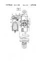
- FIG. 1shows in partial cross-section a hydraulic shock-damper assembly as known from the present state of the art.
- FIG. 2shows in partial cross-section an embodiment of the hydraulic shock-damper in accordance with the invention.
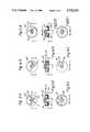
- FIGS. 3, 4 and 5show embodiments of combinations of controllable closure means and non-return valves applied in the shock-damper according to the invention and
- FIG. 3Ashows a first embodiment of a combination of a controllable closure means and a non-return valve applied in the shock-damper according to the invention.
- FIG. 3Bis a sectional view taken along Plane A--A in FIG. 3A.
- FIG. 3Cis a sectional view taken along Plane D--D in FIG. 3B.
- FIG. 4Ashows a second embodiment of a combination of a controllable closure means and a non-return valve applied in the shock-damper according to the invention.
- FIG. 4Bis a sectional view taken along Plane B--B in FIG. 4A.
- FIG. 4Cis a sectional view taken along Plane E--E in FIG. 4B.
- FIG. 5Ashows a third embodiment of a combination of a controllable closure means and a non-return valve applied in the shock-damper according to the invention.
- FIG. 5Bis a sectional view taken along Plane C--C in FIG. 5A.
- FIG. 5Cis a sectional view taken along Plane F--F in FIG. 5B.
- the known shock-damper shown in FIG. 1 and which is applied in particular as a shock-damper for the rear-wheel of a rally-cross motorcyclecomprises a cylinder 1 accomodating a hydraulic damping fluid which is generally oil, and also a displacable piston 2 therein which is provided with a hollow piston-rod 3.
- the cylinder 1is divided into an upper chamber and a lower chamber whilst the piston 2 is provided with a number of holes 4 which are covered-off with one or more spacer-plates 5 on the side of the piston 2 opposite to that of the piston-rod 3.
- spacer-plates 5serve as valves and are spring-loaded by a compression-spring 6 which rests against the spacer-plates at one of its ends and supports an end-portion 7' of a setting-spindle 7 at the other one of its ends, the setting-spindle 7 extending out from the hollow piston-rod 3.
- the setting-spindle 7forms a part of the mechanism for regulating the damping output and which mechanism comprises a setting-nut 7" by which means the position of the setting-spindle 7 can be set with respect to the piston 2 and by which means the force imposed by the compression spring 6 can thus be set also.
- the known type of shock-damperalso includes a dashpot 8 which serves to compensate for the spatial volume occupied by the piston-rod and the lower end of which is closed.
- This dashpotalso accomodates a displacable partitioning element 9 which is in the form of a dome shaped diaphragm.
- the space between the closed lower end of the dashpot 8 and the partitioning element 9is filled with a fluid under pressure, an inert gas for example.
- the space in the dashpot on the other side of the membrane 9is connected to the upper chamber of the cylinder 1 via a flow-channel 10 which can be constituted by a flexible tube joining the dashpot 8 with the upper chamber of the cylinder 1.
- a flow-channel 10which can be constituted by a flexible tube joining the dashpot 8 with the upper chamber of the cylinder 1.
- the channel 10is accomodated in a housing 11 which is in turn connected at one end to the dashpot 8 and at the other end to the cylinder 1.
- a valve 12is fitted in the channel 10 and the flow passage through the valve is regulated from the exterior by means of an operating knob 13 which sets the damping input of the shock-damper.
- FIG. 2shows an embodiment of the hydraulic shock-damper according to the invention.
- This fig.shows a cylinder 21 surrounded by a concentrically fitted second cylinder 22 such that a space 23 is provided between both cylinders.
- Cylinder 21is fitted with a displaceable piston 24 having a number of holes 25 therethrough and separating the cylinder 21 into upper and lower chambers, this piston 24 being mounted on a solid piston-rod 26.
- An open connectionis provided close to the lower end of the cylinder 21 and running from the latter's lower chamber to the space 23.
- this embodimentalso includes a dashpot 27 accomodating a displaceable partitioning element 28.
- the space beneath the partitioning element 28is filled with a fluid, such as nitrogen for example, under a pressure of 14 atmospheres.
- a housing 29is provided in which a channel 30 is provided that emerges at one end into the dashpot 27 and at its other end into the upper chamber of cylinder 21.
- Two branch lines 31 and 32respectively are connected to the channel 30 and merge into a common line 37 which then emerges into the space 23 between the two cylinders 21 and 22.
- Combination assemblies I and IIeach including a closure means and a non-return valve, are fitted in the branch lines 31 and 32 respectively. Embodiments of such assemblies are further to be described with reference to FIGS. 3, 4 and 5.
- the non-return valves of assemblies I and IIare designed in such a manner that they open in opposing directions of the flow of the damping fluid.
- the operating spindles for the assemblies I and IIextend through to the outside of the housing 29 so that the valves are operable from the exterior.
- the housing 29When fitted to a motorcycle, the housing 29 is located close to or under the driver's saddle so that, if desired, he can operate both valves whilst riding.
- FIG. 3shows a practical embodiment of a closure means/non-return valve assembly I for example, and which is fitted to the shock-damper according to the invention and shown in FIG. 2.
- the assemblycomprises a disc 40 having a number of axially arranged apertures 41 extending therethrough and distributed over an arc, and which apertures engage at their lower ends with at least one springy plate 42 which serves as a non-return valve.
- the axially arranged apertures 41emerge into a common chamber 45 in the form of an annular recess in the disc 40.
- the advantage of this embodimentis that irrespective of the number of flow-through apertures 41 being open, the springy non-return valve is evenly loaded by pressure of the fluid pressure medium applied thereto.
- a control plate 43, of circular-segmental formis affixed to a control spindle 44 which can be turned with the aid of an operating knob 45 (see FIG. 2).
- the control plate 43 of circular-segmental formis adjustable with respect to the aperture 41 in the disc 40 such that the total number of flow-through apertures in the disc 40 can be adjusted.
- the assembly IIis fitted in a reverse arrangement in the housing 29 but for the rest it is the same as assembly I.
- FIG. 2is illustrative of the operation of the shock-damper according to the invention.
- the damping actionis partially obtained in the conventional manner by the movement of the piston 24 with the apertures 25 therethrough in the oil-filled cylinder 21.
- the damping effectis obtained further in the following manner: on the input stroke (with the piston moving upward as in FIG. 2) a higher oil-pressure arises on the upper side of the piston than on the lower side thereof as the result of the resistance-to-flow of the piston.
- This pressure-differenceis used to divert part of the oil such that the oil flows, via the closure means and non-return valve of the assembly I, through the channel 30 to the common line 37 and to the intermediate space 23 and then following to the lower chamber of the cylinder 21.
- the springy plate 42 of assembly II acting as a non-return valveinhibits the flow of the fluid through the disc 40 of this assembly.
- On the output strokethe oil flows now through assembly II and the non-return valve of assembly I (plate 42 against disc 40) is closed.
- FIGS. 4 and 5show still other embodiments of combinations of controllable means and non-return valves which can be used in shock-dampers according to the invention.
- FIG. 4shows an embodiment in which the disc 46 is provided with a groove-like flow passage 47 into which groove a lip 49 on a rotatable control-plate 48 extends whereby not only the flow-debit of the valve is determined but also the surface area to which pressure is operative on the non-return valve.
- An advantage of this embodimentis that a continuously variable adjustment can be made.
- an axial aperture 51is provided in a disc-like element 50 which emerges into a chamber 52 in the form of an annular recess on one side of the disc.
- a partially disc-like control plate 53 being rotatable with respect to disc 50,is bordered on its periphery by a surface 54 bent in such a manner that on rotating the control plate, the flow-through aperture 51 is opened or closed gradually in order to regulate the flow debit of the damping fluid.
- FIGS. 6 and 7show schematically some modified embodiments of the shock-damper according to the invention.
- a main lineis provided which emerge at its different ends into the upper and lower chambers respectively of the cylinder 61.
- Two branch lines 62 and 63 arranged in parallelare incorporated in the line 60 and in which branch lines a valve 64 and a non-return valve 66 are incorporated in branch line 62 and a valve 65 and a non-return valve 67 are incorporated in the branch line 63.
- the non-return valvesopen in opposing directions.
- the shock-dampercomprises two lines 70, 71, each of which is emerging into the upper and lower chambers of a cylinder 72.
- each line valves 73 and 74 respectively and non-return valves 75 and 76 respectivelyare mounted, the non-return valve opening again in opposing directions.
- the schematically shown embodiments in FIGS. 6 and 7, in which no double-walled cylinder is required,are particularly suitable for such applications in which the damper is not encircled by a spring (such as shown in the example of FIG. 2) but where the spring is fitted in some other place such as is often the case with automobiles.
Landscapes
- Engineering & Computer Science (AREA)
- General Engineering & Computer Science (AREA)
- Mechanical Engineering (AREA)
- Axle Suspensions And Sidecars For Cycles (AREA)
- Fluid-Damping Devices (AREA)
Abstract
Description
Claims (4)
Applications Claiming Priority (2)
| Application Number | Priority Date | Filing Date | Title |
|---|---|---|---|
| NL8600211ANL8600211A (en) | 1986-01-30 | 1986-01-30 | HYDRAULIC SHOCK ABSORBER. |
| NL8600211 | 1986-01-30 |
Publications (1)
| Publication Number | Publication Date |
|---|---|
| US4732244Atrue US4732244A (en) | 1988-03-22 |
Family
ID=19847484
Family Applications (1)
| Application Number | Title | Priority Date | Filing Date |
|---|---|---|---|
| US07/007,376Expired - LifetimeUS4732244A (en) | 1986-01-30 | 1987-01-27 | Hydraulic shock damper assembly for use in vehicles |
Country Status (5)
| Country | Link |
|---|---|
| US (1) | US4732244A (en) |
| EP (1) | EP0237085B1 (en) |
| JP (1) | JPS62215138A (en) |
| DE (1) | DE3761395D1 (en) |
| NL (1) | NL8600211A (en) |
Cited By (90)
| Publication number | Priority date | Publication date | Assignee | Title |
|---|---|---|---|---|
| US4834088A (en)* | 1987-03-02 | 1989-05-30 | Jimecal | Shock absorber for vehicles with pneumatic suspension, more especially for heavy vehicles |
| US4872537A (en)* | 1988-06-06 | 1989-10-10 | Brian Warner | Adjustable damper means for shock absorber |
| DE3925074A1 (en)* | 1988-07-29 | 1990-02-01 | Mazda Motor | SUSPENSION SYSTEM FOR A MOTOR VEHICLE |
| US4962912A (en)* | 1988-10-01 | 1990-10-16 | Festo Kg | Rate of flow control valve |
| WO1990012220A1 (en)* | 1989-04-05 | 1990-10-18 | Tooling Promotion Ab | Hydraulic device for chairs |
| US5148896A (en)* | 1991-07-01 | 1992-09-22 | The Boeing Company | High pressure hydropneumatic shock absorber |
| US5172794A (en)* | 1991-04-03 | 1992-12-22 | Maremont Corporation | Adjustable damping shock absorber |
| US5351790A (en)* | 1991-06-20 | 1994-10-04 | Tokico Ltd. | Hydraulic suspension device for automobile |
| US5398996A (en)* | 1992-08-12 | 1995-03-21 | Ford Motor Company | Blow-molded headrest armature assembly |
| US5431259A (en)* | 1992-11-20 | 1995-07-11 | Tokico, Ltd. | Damping force control type hydraulic shock absorber |
| US5458218A (en)* | 1992-12-16 | 1995-10-17 | Hemscheidt Fahrwerktechnik Gmbh & Co. Kg | Suspension system for motor vehicles as well as damping valve for said suspension system |
| EP0723090A3 (en)* | 1995-01-19 | 1998-06-10 | Hunger, Walter, Dr.-Ing. E.h. | Hydropneumatic strut, in particular for bicycle fork |
| US5957252A (en)* | 1996-08-02 | 1999-09-28 | Berthold; Brian D. | Hydraulic suspension unit |
| US6029958A (en)* | 1996-06-25 | 2000-02-29 | Ohlins Racing Ab | Shock absorber |
| US6105740A (en)* | 1997-07-23 | 2000-08-22 | Marzocchi S.P.A. | Hydraulic shock absorber |
| EP1085232A1 (en)* | 1998-03-31 | 2001-03-21 | Donerre Amortisseur | Adjustment device for a hydraulic shock absorber |
| US6220408B1 (en)* | 1997-12-11 | 2001-04-24 | Mannesmann Sachs Ag | Spring and damper unit with external storage device |
| US6318525B1 (en)* | 1999-05-07 | 2001-11-20 | Marzocchi, S.P.A. | Shock absorber with improved damping |
| FR2811390A1 (en)* | 2000-07-07 | 2002-01-11 | Thierry Boccage | Damping assembly for rear wheel of motorcycle comprises regulator controlling the fluid flow, controlled by a calculator, which processes shocks signals from the front wheel |
| US6659241B2 (en)* | 2001-08-22 | 2003-12-09 | Meritor Heavy Vehicle Technology, Llc | Shock absorber compression damping adjustment |
| US20030230458A1 (en)* | 2002-03-18 | 2003-12-18 | Smith S. Gregory | Variable response bushing |
| US6880684B1 (en)* | 2003-07-18 | 2005-04-19 | Walker Evans | Flow regulator for a gas shock absorber |
| US20050173213A1 (en)* | 2001-06-12 | 2005-08-11 | Vincent Coquet | Multipurpose hydraulic shock absorber for vehicle |
| US20050173849A1 (en)* | 2004-02-10 | 2005-08-11 | Bart Vandewal | Electronically controlled frequency dependent damping |
| US20050206117A1 (en)* | 2004-03-17 | 2005-09-22 | Dirk Temmerman | Air suspension system for motorcycles and bicycles |
| US20060011432A1 (en)* | 2002-05-29 | 2006-01-19 | Progressive Suspension, Inc. | Hydraulic dampers with pressure regulated control valve |
| US20060021833A1 (en)* | 2004-04-08 | 2006-02-02 | Hemscheidt Fahrwerktechnik Gmbh & Co. Kg | Suspension and damping device for motor vehicles |
| US20060027989A1 (en)* | 2004-08-06 | 2006-02-09 | Aircell Engineering, Inc. | Control system for motorcycle fork |
| US20070017760A1 (en)* | 2005-07-18 | 2007-01-25 | Hemscheidt Fahrwerktechnik Gmbh & Co. | Suspension arrangement for motor vehicles |
| US20070119672A1 (en)* | 2005-11-29 | 2007-05-31 | Fox Factory, Inc. | Damping cylinder with annular bladder |
| US20070252349A1 (en)* | 2006-04-26 | 2007-11-01 | Kayaba Industry Co., Ltd. | Rear wheel suspension device for two-wheel vehicle |
| US20080007027A1 (en)* | 1999-04-06 | 2008-01-10 | Specialized Bicycle Components, Inc. | Bicycle damping enhancement system |
| US20090277734A1 (en)* | 2008-05-09 | 2009-11-12 | Christopher Paul Cox | Methods and apparatus for position sensitive suspension dampening |
| US20100018818A1 (en)* | 2007-02-06 | 2010-01-28 | Ohlins Racing Ab | Shock absorber with hydraulic flow ducts |
| US20100116608A1 (en)* | 2004-04-08 | 2010-05-13 | Hemscheidt Fahrwerktechnik Gmbh & Co. Kg | Suspension and damping device for motor vehicles |
| US20100140884A1 (en)* | 2004-04-08 | 2010-06-10 | Samsung Electronics Co., Ltd. | Suspension and damping device for motor vehicles |
| US20110017559A1 (en)* | 2007-05-16 | 2011-01-27 | Ohlins Racing Ab | Pressure reservoir for shock absorber |
| US8162112B2 (en) | 2007-02-09 | 2012-04-24 | Competition Tire East | Methods and apparatus for protecting a shock absorber from bottoming |
| US20120136537A1 (en)* | 2009-03-19 | 2012-05-31 | Mario Galasso | Methods and Apparatus for Suspension Adjustment |
| US20140054122A1 (en)* | 2012-08-27 | 2014-02-27 | Cane Creek Cycling Components | Twin tube style damper with selectable bypass flow passages |
| US20140084565A1 (en)* | 2011-05-31 | 2014-03-27 | Honda Motor Co., Ltd. | Two-wheeled motor vehicle |
| US8931604B2 (en)* | 2013-05-30 | 2015-01-13 | GM Global Technology Operations LLC | Damper assembly with monotube and dynamic compression valve and vehicle having same |
| US9140325B2 (en) | 2009-03-19 | 2015-09-22 | Fox Factory, Inc. | Methods and apparatus for selective spring pre-load adjustment |
| US20150285325A1 (en)* | 2003-07-08 | 2015-10-08 | Fox Factory, Inc. | Damper with pressure-sensitive compression damping |
| US20150290991A1 (en)* | 2014-04-11 | 2015-10-15 | Fox Factory, Inc. | Twin tube damper with remote gas reservoir |
| EP2068034A3 (en)* | 2007-12-03 | 2016-04-20 | Francisco Javier Muñoz Labrador | Pro-active magnetorheological suspension system |
| US9725023B2 (en) | 2015-05-15 | 2017-08-08 | Polaris Industries Inc. | Utility vehicle |
| US9821623B1 (en)* | 2016-07-11 | 2017-11-21 | Chih-Hsien Liao | Adjustable shock absorber |
| US9885398B2 (en)* | 2013-12-20 | 2018-02-06 | Kyb Corporation | Shock absorber |
| US10036443B2 (en) | 2009-03-19 | 2018-07-31 | Fox Factory, Inc. | Methods and apparatus for suspension adjustment |
| US10060499B2 (en) | 2009-01-07 | 2018-08-28 | Fox Factory, Inc. | Method and apparatus for an adjustable damper |
| US10086892B2 (en) | 2010-07-02 | 2018-10-02 | Fox Factory, Inc. | Lever assembly for positive lock adjustable seat post |
| US10086670B2 (en) | 2009-03-19 | 2018-10-02 | Fox Factory, Inc. | Methods and apparatus for suspension set up |
| US10145438B2 (en)* | 2016-03-30 | 2018-12-04 | Showa Corporation | Shock absorber |
| US10330171B2 (en) | 2012-05-10 | 2019-06-25 | Fox Factory, Inc. | Method and apparatus for an adjustable damper |
| US10336148B2 (en) | 2009-01-07 | 2019-07-02 | Fox Factory, Inc. | Method and apparatus for an adjustable damper |
| US10400847B2 (en) | 2009-01-07 | 2019-09-03 | Fox Factory, Inc. | Compression isolator for a suspension damper |
| US10406883B2 (en) | 2009-10-13 | 2019-09-10 | Fox Factory, Inc. | Methods and apparatus for controlling a fluid damper |
| US10415662B2 (en) | 2009-01-07 | 2019-09-17 | Fox Factory, Inc. | Remotely operated bypass for a suspension damper |
| US10443671B2 (en) | 2009-01-07 | 2019-10-15 | Fox Factory, Inc. | Remotely operated bypass for a suspension damper |
| US10472013B2 (en) | 2008-11-25 | 2019-11-12 | Fox Factory, Inc. | Seat post |
| USD866408S1 (en) | 2017-08-28 | 2019-11-12 | Qa1 Precision Products, Inc. | Shock absorber |
| USD869259S1 (en) | 2017-08-28 | 2019-12-10 | Qa1 Precision Products, Inc. | Valve component |
| USD872837S1 (en) | 2017-08-28 | 2020-01-14 | Qa1 Precision Products, Inc. | Bleed needle |
| US10537790B2 (en) | 2008-11-25 | 2020-01-21 | Fox Factory, Inc. | Methods and apparatus for virtual competition |
| US10550909B2 (en) | 2008-08-25 | 2020-02-04 | Fox Factory, Inc. | Methods and apparatus for suspension lock out and signal generation |
| US10670106B2 (en) | 2009-01-07 | 2020-06-02 | Fox Factory, Inc. | Method and apparatus for an adjustable damper |
| US10677309B2 (en) | 2011-05-31 | 2020-06-09 | Fox Factory, Inc. | Methods and apparatus for position sensitive suspension damping |
| US10697514B2 (en) | 2010-01-20 | 2020-06-30 | Fox Factory, Inc. | Remotely operated bypass for a suspension damper |
| US10723409B2 (en) | 2009-01-07 | 2020-07-28 | Fox Factory, Inc. | Method and apparatus for an adjustable damper |
| US10737546B2 (en)* | 2016-04-08 | 2020-08-11 | Fox Factory, Inc. | Electronic compression and rebound control |
| US10766533B2 (en) | 2015-12-10 | 2020-09-08 | Polaris Industries Inc. | Utility vehicle |
| US10781879B2 (en) | 2009-01-07 | 2020-09-22 | Fox Factory, Inc. | Bypass for a suspension damper |
| US10821795B2 (en) | 2009-01-07 | 2020-11-03 | Fox Factory, Inc. | Method and apparatus for an adjustable damper |
| US10946736B2 (en) | 2018-06-05 | 2021-03-16 | Polaris Industries Inc. | All-terrain vehicle |
| US10995465B2 (en)* | 2016-12-22 | 2021-05-04 | Vetco Gray Scandinavia As | Damper for absorbing shock generated upon docking a moving structure with a stationary structure or foundation |
| US11085502B2 (en) | 2017-08-28 | 2021-08-10 | Qa1 Precision Products, Inc. | Bleed needle for a hydraulic system |
| US11105390B2 (en) | 2017-08-28 | 2021-08-31 | Qa1 Precision Products, Inc. | Shock absorber with dry valving |
| US11279199B2 (en) | 2012-01-25 | 2022-03-22 | Fox Factory, Inc. | Suspension damper with by-pass valves |
| US11299233B2 (en) | 2009-01-07 | 2022-04-12 | Fox Factory, Inc. | Method and apparatus for an adjustable damper |
| US11306798B2 (en) | 2008-05-09 | 2022-04-19 | Fox Factory, Inc. | Position sensitive suspension damping with an active valve |
| US11448282B2 (en)* | 2018-06-20 | 2022-09-20 | N10Z Performance Shocks LLC | Shock absorber assembly |
| US11535336B2 (en)* | 2019-06-27 | 2022-12-27 | Honda Motor Co., Ltd. | Saddle riding vehicle |
| US11859690B2 (en) | 2009-10-13 | 2024-01-02 | Fox Factory, Inc. | Suspension system |
| US20240093748A1 (en)* | 2022-08-05 | 2024-03-21 | Michael Torre | Single piece shock body |
| US12122205B2 (en) | 2009-01-07 | 2024-10-22 | Fox Factory, Inc. | Active valve for an internal bypass |
| US12172518B2 (en) | 2019-04-30 | 2024-12-24 | Polaris Industries Inc. | Vehicle |
| US12187127B2 (en) | 2020-05-15 | 2025-01-07 | Polaris Industries Inc. | Off-road vehicle |
| US12385429B2 (en) | 2022-06-13 | 2025-08-12 | Polaris Industries Inc. | Powertrain for a utility vehicle |
| US12384464B2 (en) | 2020-05-15 | 2025-08-12 | Polaris Industries Inc. | Off-road vehicle |
Families Citing this family (12)
| Publication number | Priority date | Publication date | Assignee | Title |
|---|---|---|---|---|
| AT391801B (en)* | 1987-10-30 | 1990-12-10 | Bock Orthopaed Ind | HYDRAULIC CONTROL |
| JPH0173538U (en)* | 1987-11-06 | 1989-05-18 | ||
| DE3827255C2 (en)* | 1988-08-11 | 1999-05-27 | Teves Gmbh Alfred | Adjustable hydraulic vibration damper for motor vehicles |
| FR2640339B1 (en)* | 1988-12-09 | 1993-01-22 | Peugeot | HYDRAULIC SHOCK ABSORBER FOR FITTING A SUSPENSION MEMBER, FOR EXAMPLE OF A MOTOR VEHICLE |
| JPH07208532A (en)* | 1994-01-11 | 1995-08-11 | H K S:Kk | Damping force adjusting device for hydraulic shock absorber |
| GB2293641A (en)* | 1994-09-30 | 1996-04-03 | Keyse Robert | Shock absorber |
| FR2751713B1 (en)* | 1996-07-24 | 1998-09-18 | Donerre Amortisseur Soc | OIL SHOCK ABSORBER SYSTEM |
| SE531812C2 (en)* | 2006-11-09 | 2009-08-11 | Oehlins Racing Ab | Valve / valves intended for a shock absorber and a damper device with such valve |
| US8079602B2 (en) | 2008-06-06 | 2011-12-20 | Polaris Industries Inc. | Suspension systems for a vehicle |
| MX2010011574A (en)* | 2008-05-08 | 2010-11-10 | Polaris Inc | Suspension systems for a vehicle. |
| US7950486B2 (en) | 2008-06-06 | 2011-05-31 | Polaris Industries Inc. | Vehicle |
| CN109372932B (en)* | 2018-12-12 | 2020-08-07 | 四川凌峰航空液压机械有限公司 | Differential hydraulic damper |
Citations (8)
| Publication number | Priority date | Publication date | Assignee | Title |
|---|---|---|---|---|
| GB171192A (en)* | 1920-08-17 | 1921-11-17 | Arthur Griffiths | Appliance for use with an internal combustion engine for admitting additional air tothe carburetted mixture or fuel |
| FR2087829A5 (en)* | 1970-10-16 | 1971-12-31 | Grinnell Corp | |
| DE7503070U (en)* | 1975-02-01 | 1975-06-12 | Grammer W | Shock absorbers |
| US4153237A (en)* | 1976-11-01 | 1979-05-08 | Supalla Steven A | Hydrapneumatic suspension unit and valving structure |
| FR2412756A1 (en)* | 1977-12-22 | 1979-07-20 | Itt | ARRANGEMENT FOR ADJUSTING THE CUSHIONING OF A SHOCK ABSORBER |
| US4275900A (en)* | 1977-09-16 | 1981-06-30 | Angelo Andreoli | Fluid suspension unit for motorcycles |
| US4515253A (en)* | 1982-04-16 | 1985-05-07 | Kabushiki Kaisha Showa Seisakusho | Damping force generating device for an oil damper |
| US4544130A (en)* | 1983-08-24 | 1985-10-01 | Kurt Stoll | Choke unit |
Family Cites Families (3)
| Publication number | Priority date | Publication date | Assignee | Title |
|---|---|---|---|---|
| JPS5637453A (en)* | 1979-09-03 | 1981-04-11 | Masahiko Iwaki | Solar heat collector |
| WO1984001605A1 (en)* | 1982-10-20 | 1984-04-26 | Donald Maxwell Culley | A vibration damper |
| US4491207A (en)* | 1983-07-15 | 1985-01-01 | Lord Corporation | Fluid control means for vehicle suspension system |
- 1986
- 1986-01-30NLNL8600211Apatent/NL8600211A/ennot_activeApplication Discontinuation
- 1987
- 1987-01-26DEDE8787200105Tpatent/DE3761395D1/ennot_activeExpired - Lifetime
- 1987-01-26EPEP87200105Apatent/EP0237085B1/ennot_activeExpired - Lifetime
- 1987-01-27USUS07/007,376patent/US4732244A/ennot_activeExpired - Lifetime
- 1987-01-29JPJP62017419Apatent/JPS62215138A/enactivePending
Patent Citations (8)
| Publication number | Priority date | Publication date | Assignee | Title |
|---|---|---|---|---|
| GB171192A (en)* | 1920-08-17 | 1921-11-17 | Arthur Griffiths | Appliance for use with an internal combustion engine for admitting additional air tothe carburetted mixture or fuel |
| FR2087829A5 (en)* | 1970-10-16 | 1971-12-31 | Grinnell Corp | |
| DE7503070U (en)* | 1975-02-01 | 1975-06-12 | Grammer W | Shock absorbers |
| US4153237A (en)* | 1976-11-01 | 1979-05-08 | Supalla Steven A | Hydrapneumatic suspension unit and valving structure |
| US4275900A (en)* | 1977-09-16 | 1981-06-30 | Angelo Andreoli | Fluid suspension unit for motorcycles |
| FR2412756A1 (en)* | 1977-12-22 | 1979-07-20 | Itt | ARRANGEMENT FOR ADJUSTING THE CUSHIONING OF A SHOCK ABSORBER |
| US4515253A (en)* | 1982-04-16 | 1985-05-07 | Kabushiki Kaisha Showa Seisakusho | Damping force generating device for an oil damper |
| US4544130A (en)* | 1983-08-24 | 1985-10-01 | Kurt Stoll | Choke unit |
Cited By (185)
| Publication number | Priority date | Publication date | Assignee | Title |
|---|---|---|---|---|
| US4834088A (en)* | 1987-03-02 | 1989-05-30 | Jimecal | Shock absorber for vehicles with pneumatic suspension, more especially for heavy vehicles |
| US4872537A (en)* | 1988-06-06 | 1989-10-10 | Brian Warner | Adjustable damper means for shock absorber |
| DE3925074A1 (en)* | 1988-07-29 | 1990-02-01 | Mazda Motor | SUSPENSION SYSTEM FOR A MOTOR VEHICLE |
| US4962912A (en)* | 1988-10-01 | 1990-10-16 | Festo Kg | Rate of flow control valve |
| WO1990012220A1 (en)* | 1989-04-05 | 1990-10-18 | Tooling Promotion Ab | Hydraulic device for chairs |
| US5172794A (en)* | 1991-04-03 | 1992-12-22 | Maremont Corporation | Adjustable damping shock absorber |
| US5351790A (en)* | 1991-06-20 | 1994-10-04 | Tokico Ltd. | Hydraulic suspension device for automobile |
| US5148896A (en)* | 1991-07-01 | 1992-09-22 | The Boeing Company | High pressure hydropneumatic shock absorber |
| US5398996A (en)* | 1992-08-12 | 1995-03-21 | Ford Motor Company | Blow-molded headrest armature assembly |
| US5431259A (en)* | 1992-11-20 | 1995-07-11 | Tokico, Ltd. | Damping force control type hydraulic shock absorber |
| US5458218A (en)* | 1992-12-16 | 1995-10-17 | Hemscheidt Fahrwerktechnik Gmbh & Co. Kg | Suspension system for motor vehicles as well as damping valve for said suspension system |
| EP0723090A3 (en)* | 1995-01-19 | 1998-06-10 | Hunger, Walter, Dr.-Ing. E.h. | Hydropneumatic strut, in particular for bicycle fork |
| US6029958A (en)* | 1996-06-25 | 2000-02-29 | Ohlins Racing Ab | Shock absorber |
| US5957252A (en)* | 1996-08-02 | 1999-09-28 | Berthold; Brian D. | Hydraulic suspension unit |
| US6086060A (en)* | 1996-08-02 | 2000-07-11 | Berthold; Brian D. | Hydraulic suspension unit |
| US6105740A (en)* | 1997-07-23 | 2000-08-22 | Marzocchi S.P.A. | Hydraulic shock absorber |
| US6220408B1 (en)* | 1997-12-11 | 2001-04-24 | Mannesmann Sachs Ag | Spring and damper unit with external storage device |
| EP1085232A1 (en)* | 1998-03-31 | 2001-03-21 | Donerre Amortisseur | Adjustment device for a hydraulic shock absorber |
| US20080007027A1 (en)* | 1999-04-06 | 2008-01-10 | Specialized Bicycle Components, Inc. | Bicycle damping enhancement system |
| US9580134B2 (en) | 1999-04-06 | 2017-02-28 | Specialized Bicycle Components, Inc. | Bicycle damping enhancement system |
| US6318525B1 (en)* | 1999-05-07 | 2001-11-20 | Marzocchi, S.P.A. | Shock absorber with improved damping |
| FR2811390A1 (en)* | 2000-07-07 | 2002-01-11 | Thierry Boccage | Damping assembly for rear wheel of motorcycle comprises regulator controlling the fluid flow, controlled by a calculator, which processes shocks signals from the front wheel |
| US20050173213A1 (en)* | 2001-06-12 | 2005-08-11 | Vincent Coquet | Multipurpose hydraulic shock absorber for vehicle |
| US6659241B2 (en)* | 2001-08-22 | 2003-12-09 | Meritor Heavy Vehicle Technology, Llc | Shock absorber compression damping adjustment |
| WO2003080373A3 (en)* | 2002-03-18 | 2004-06-03 | S Gregory Smith | Variable response bushing |
| US8627930B2 (en) | 2002-03-18 | 2014-01-14 | S. Gregory Smith | Variable response bushing |
| US20030230458A1 (en)* | 2002-03-18 | 2003-12-18 | Smith S. Gregory | Variable response bushing |
| US7308976B2 (en) | 2002-05-29 | 2007-12-18 | Turner Technology Group | Hydraulic dampers with pressure regulated control valve |
| US20060011432A1 (en)* | 2002-05-29 | 2006-01-19 | Progressive Suspension, Inc. | Hydraulic dampers with pressure regulated control valve |
| US10352392B2 (en)* | 2003-07-08 | 2019-07-16 | Fox Factory, Inc. | Damper with pressure-sensitive compression damping |
| US20150285325A1 (en)* | 2003-07-08 | 2015-10-08 | Fox Factory, Inc. | Damper with pressure-sensitive compression damping |
| US11293515B2 (en) | 2003-07-08 | 2022-04-05 | Fox Factory, Inc. | Damper with pressure-sensitive compression damping |
| US6880684B1 (en)* | 2003-07-18 | 2005-04-19 | Walker Evans | Flow regulator for a gas shock absorber |
| US20050173849A1 (en)* | 2004-02-10 | 2005-08-11 | Bart Vandewal | Electronically controlled frequency dependent damping |
| US20080006494A1 (en)* | 2004-02-10 | 2008-01-10 | Bart Vandewal | Electronically controlled frequency dependent damping |
| US20080006495A1 (en)* | 2004-02-10 | 2008-01-10 | Bart Vandewal | Electronically controlled frequency dependent damping |
| US7413062B2 (en) | 2004-02-10 | 2008-08-19 | Tenneco Automotive Operating Company Inc. | Electronically controlled frequency dependent damping |
| US8210330B2 (en) | 2004-02-10 | 2012-07-03 | Tenneco Automotive Operating Company Inc. | Electronically controlled frequency dependent damping |
| US7284766B2 (en) | 2004-03-17 | 2007-10-23 | Dirk Temmerman | Air suspension system for motorcycles and bicycles |
| US20050206117A1 (en)* | 2004-03-17 | 2005-09-22 | Dirk Temmerman | Air suspension system for motorcycles and bicycles |
| US8151953B2 (en) | 2004-04-08 | 2012-04-10 | Samsung Electronics Co., Ltd. | Suspension and damping device for motor vehicles |
| US20060021833A1 (en)* | 2004-04-08 | 2006-02-02 | Hemscheidt Fahrwerktechnik Gmbh & Co. Kg | Suspension and damping device for motor vehicles |
| US20100116608A1 (en)* | 2004-04-08 | 2010-05-13 | Hemscheidt Fahrwerktechnik Gmbh & Co. Kg | Suspension and damping device for motor vehicles |
| US20100140884A1 (en)* | 2004-04-08 | 2010-06-10 | Samsung Electronics Co., Ltd. | Suspension and damping device for motor vehicles |
| US7469914B2 (en)* | 2004-08-06 | 2008-12-30 | Aircell Engineering, Inc. | Control system for motorcycle fork |
| US20060027989A1 (en)* | 2004-08-06 | 2006-02-09 | Aircell Engineering, Inc. | Control system for motorcycle fork |
| US7766136B2 (en) | 2005-07-18 | 2010-08-03 | Hemscheidt Fahrwerktechnik Gmbh & Co. Kg | Suspension arrangement for motor vehicles |
| US20070017760A1 (en)* | 2005-07-18 | 2007-01-25 | Hemscheidt Fahrwerktechnik Gmbh & Co. | Suspension arrangement for motor vehicles |
| US20110005877A1 (en)* | 2005-11-29 | 2011-01-13 | Fox Factory, Inc. | Damping cylinder with annular bladder |
| US7921974B2 (en) | 2005-11-29 | 2011-04-12 | Fox Factory, Inc. | Damping cylinder with annular bladder |
| US20070119672A1 (en)* | 2005-11-29 | 2007-05-31 | Fox Factory, Inc. | Damping cylinder with annular bladder |
| US8342488B2 (en) | 2005-11-29 | 2013-01-01 | Fox Factory, Inc. | Damping cylinder with annular bladder |
| US7744097B2 (en)* | 2006-04-26 | 2010-06-29 | Kayaba Industry Co., Ltd. | Rear wheel suspension device for two-wheel vehicle |
| US20070252349A1 (en)* | 2006-04-26 | 2007-11-01 | Kayaba Industry Co., Ltd. | Rear wheel suspension device for two-wheel vehicle |
| US9091319B2 (en)* | 2007-02-06 | 2015-07-28 | Ohlins Racing Ab | Shock absorber with hydraulic flow ducts |
| US20100018818A1 (en)* | 2007-02-06 | 2010-01-28 | Ohlins Racing Ab | Shock absorber with hydraulic flow ducts |
| US8162112B2 (en) | 2007-02-09 | 2012-04-24 | Competition Tire East | Methods and apparatus for protecting a shock absorber from bottoming |
| US20110017559A1 (en)* | 2007-05-16 | 2011-01-27 | Ohlins Racing Ab | Pressure reservoir for shock absorber |
| EP2068034A3 (en)* | 2007-12-03 | 2016-04-20 | Francisco Javier Muñoz Labrador | Pro-active magnetorheological suspension system |
| US9303712B2 (en) | 2008-05-09 | 2016-04-05 | Fox Factory, Inc. | Methods and apparatus for position sensitive suspension damping |
| US11131361B2 (en) | 2008-05-09 | 2021-09-28 | Fox Factory, Inc. | Methods and apparatus for position sensitive suspension damping |
| US8550223B2 (en)* | 2008-05-09 | 2013-10-08 | Fox Factory, Inc. | Methods and apparatus for position sensitive suspension dampening |
| US11306798B2 (en) | 2008-05-09 | 2022-04-19 | Fox Factory, Inc. | Position sensitive suspension damping with an active valve |
| US10054185B2 (en) | 2008-05-09 | 2018-08-21 | Fox Factory, Inc. | Methods and apparatus for position sensitive suspension damping |
| US20090277734A1 (en)* | 2008-05-09 | 2009-11-12 | Christopher Paul Cox | Methods and apparatus for position sensitive suspension dampening |
| US10550909B2 (en) | 2008-08-25 | 2020-02-04 | Fox Factory, Inc. | Methods and apparatus for suspension lock out and signal generation |
| US11162555B2 (en) | 2008-08-25 | 2021-11-02 | Fox Factory, Inc. | Methods and apparatus for suspension lock out and signal generation |
| US11257582B2 (en) | 2008-11-25 | 2022-02-22 | Fox Factory, Inc. | Methods and apparatus for virtual competition |
| US11869651B2 (en) | 2008-11-25 | 2024-01-09 | Fox Factory, Inc. | Methods and apparatus for virtual competition |
| US11875887B2 (en) | 2008-11-25 | 2024-01-16 | Fox Factory, Inc. | Methods and apparatus for virtual competition |
| US12170137B2 (en) | 2008-11-25 | 2024-12-17 | Fox Factory, Inc. | Methods and apparatus for virtual competition |
| US11043294B2 (en) | 2008-11-25 | 2021-06-22 | Fox Factoory, Inc. | Methods and apparatus for virtual competition |
| US11021204B2 (en) | 2008-11-25 | 2021-06-01 | Fox Factory, Inc. | Seat post |
| US11897571B2 (en) | 2008-11-25 | 2024-02-13 | Fox Factory, Inc. | Seat post |
| US10537790B2 (en) | 2008-11-25 | 2020-01-21 | Fox Factory, Inc. | Methods and apparatus for virtual competition |
| US10472013B2 (en) | 2008-11-25 | 2019-11-12 | Fox Factory, Inc. | Seat post |
| US11961602B2 (en) | 2008-11-25 | 2024-04-16 | Fox Factory, Inc. | Methods and apparatus for virtual competition |
| US12033739B2 (en) | 2008-11-25 | 2024-07-09 | Fox Factory, Inc. | Methods and apparatus for virtual competition |
| US10415662B2 (en) | 2009-01-07 | 2019-09-17 | Fox Factory, Inc. | Remotely operated bypass for a suspension damper |
| US11173765B2 (en) | 2009-01-07 | 2021-11-16 | Fox Factory, Inc. | Method and apparatus for an adjustable damper |
| US11519477B2 (en) | 2009-01-07 | 2022-12-06 | Fox Factory, Inc. | Compression isolator for a suspension damper |
| US11499601B2 (en) | 2009-01-07 | 2022-11-15 | Fox Factory, Inc. | Remotely operated bypass for a suspension damper |
| US11660924B2 (en) | 2009-01-07 | 2023-05-30 | Fox Factory, Inc. | Method and apparatus for an adjustable damper |
| US12377699B2 (en) | 2009-01-07 | 2025-08-05 | Fox Factory, Inc. | Method and apparatus for an adjustable damper |
| US12371122B2 (en) | 2009-01-07 | 2025-07-29 | Fox Factory, Inc. | Method and apparatus for an adjustable damper |
| US10336148B2 (en) | 2009-01-07 | 2019-07-02 | Fox Factory, Inc. | Method and apparatus for an adjustable damper |
| US10336149B2 (en) | 2009-01-07 | 2019-07-02 | Fox Factory, Inc. | Method and apparatus for an adjustable damper |
| US11408482B2 (en) | 2009-01-07 | 2022-08-09 | Fox Factory, Inc. | Bypass for a suspension damper |
| US10400847B2 (en) | 2009-01-07 | 2019-09-03 | Fox Factory, Inc. | Compression isolator for a suspension damper |
| US11299233B2 (en) | 2009-01-07 | 2022-04-12 | Fox Factory, Inc. | Method and apparatus for an adjustable damper |
| US11794543B2 (en) | 2009-01-07 | 2023-10-24 | Fox Factory, Inc. | Method and apparatus for an adjustable damper |
| US12257871B2 (en) | 2009-01-07 | 2025-03-25 | Fox Factory, Inc. | Method and apparatus for an adjustable damper |
| US10443671B2 (en) | 2009-01-07 | 2019-10-15 | Fox Factory, Inc. | Remotely operated bypass for a suspension damper |
| US11549565B2 (en) | 2009-01-07 | 2023-01-10 | Fox Factory, Inc. | Method and apparatus for an adjustable damper |
| US11168758B2 (en) | 2009-01-07 | 2021-11-09 | Fox Factory, Inc. | Method and apparatus for an adjustable damper |
| US12134293B2 (en) | 2009-01-07 | 2024-11-05 | Fox Factory, Inc. | Method and apparatus for an adjustable damper |
| US12122205B2 (en) | 2009-01-07 | 2024-10-22 | Fox Factory, Inc. | Active valve for an internal bypass |
| US11866120B2 (en) | 2009-01-07 | 2024-01-09 | Fox Factory, Inc. | Method and apparatus for an adjustable damper |
| US12091122B2 (en) | 2009-01-07 | 2024-09-17 | Fox Factory, Inc. | Method and apparatus for an adjustable damper |
| US12044286B2 (en) | 2009-01-07 | 2024-07-23 | Fox Factory, Inc. | Compression isolator for a suspension damper |
| US11890908B2 (en) | 2009-01-07 | 2024-02-06 | Fox Factory, Inc. | Method and apparatus for an adjustable damper |
| US10670106B2 (en) | 2009-01-07 | 2020-06-02 | Fox Factory, Inc. | Method and apparatus for an adjustable damper |
| US10821795B2 (en) | 2009-01-07 | 2020-11-03 | Fox Factory, Inc. | Method and apparatus for an adjustable damper |
| US10814689B2 (en) | 2009-01-07 | 2020-10-27 | Fox Factory, Inc. | Method and apparatus for an adjustable damper |
| US10723409B2 (en) | 2009-01-07 | 2020-07-28 | Fox Factory, Inc. | Method and apparatus for an adjustable damper |
| US10807433B2 (en) | 2009-01-07 | 2020-10-20 | Fox Factory, Inc. | Method and apparatus for an adjustable damper |
| US10060499B2 (en) | 2009-01-07 | 2018-08-28 | Fox Factory, Inc. | Method and apparatus for an adjustable damper |
| US11976706B2 (en) | 2009-01-07 | 2024-05-07 | Fox Factory, Inc. | Remotely operated bypass for a suspension damper |
| US10781879B2 (en) | 2009-01-07 | 2020-09-22 | Fox Factory, Inc. | Bypass for a suspension damper |
| US10800220B2 (en) | 2009-01-07 | 2020-10-13 | Fox Factory, Inc. | Method and apparatus for an adjustable damper |
| US12163569B2 (en) | 2009-03-19 | 2024-12-10 | Fox Factory, Inc. | Methods and apparatus for suspension adjustment |
| US9682604B2 (en) | 2009-03-19 | 2017-06-20 | Fox Factory, Inc. | Methods and apparatus for selective spring pre-load adjustment |
| US11619278B2 (en) | 2009-03-19 | 2023-04-04 | Fox Factory, Inc. | Methods and apparatus for suspension adjustment |
| US10086670B2 (en) | 2009-03-19 | 2018-10-02 | Fox Factory, Inc. | Methods and apparatus for suspension set up |
| US11655873B2 (en) | 2009-03-19 | 2023-05-23 | Fox Factory, Inc. | Methods and apparatus for suspension adjustment |
| US11920655B2 (en) | 2009-03-19 | 2024-03-05 | Fox Factory, Inc. | Methods and apparatus for suspension adjustment |
| US10591015B2 (en) | 2009-03-19 | 2020-03-17 | Fox Factory, Inc. | Methods and apparatus for suspension adjustment |
| US8936139B2 (en)* | 2009-03-19 | 2015-01-20 | Fox Factory, Inc. | Methods and apparatus for suspension adjustment |
| US10145435B2 (en) | 2009-03-19 | 2018-12-04 | Fox Factory, Inc. | Methods and apparatus for suspension adjustment |
| US10414236B2 (en) | 2009-03-19 | 2019-09-17 | Fox Factory, Inc. | Methods and apparatus for selective spring pre-load adjustment |
| US12103349B2 (en) | 2009-03-19 | 2024-10-01 | Fox Factory, Inc. | Methods and apparatus for selective spring pre-load adjustment |
| US11413924B2 (en) | 2009-03-19 | 2022-08-16 | Fox Factory, Inc. | Methods and apparatus for selective spring pre-load adjustment |
| US9523406B2 (en)* | 2009-03-19 | 2016-12-20 | Fox Factory, Inc. | Methods and apparatus for suspension adjustment |
| US10036443B2 (en) | 2009-03-19 | 2018-07-31 | Fox Factory, Inc. | Methods and apparatus for suspension adjustment |
| US9186949B2 (en) | 2009-03-19 | 2015-11-17 | Fox Factory, Inc. | Methods and apparatus for suspension adjustment |
| US9140325B2 (en) | 2009-03-19 | 2015-09-22 | Fox Factory, Inc. | Methods and apparatus for selective spring pre-load adjustment |
| US20120136537A1 (en)* | 2009-03-19 | 2012-05-31 | Mario Galasso | Methods and Apparatus for Suspension Adjustment |
| US10406883B2 (en) | 2009-10-13 | 2019-09-10 | Fox Factory, Inc. | Methods and apparatus for controlling a fluid damper |
| US11279198B2 (en) | 2009-10-13 | 2022-03-22 | Fox Factory, Inc. | Methods and apparatus for controlling a fluid damper |
| US12005755B2 (en) | 2009-10-13 | 2024-06-11 | Fox Factory, Inc. | Methods and apparatus for controlling a fluid damper |
| US11859690B2 (en) | 2009-10-13 | 2024-01-02 | Fox Factory, Inc. | Suspension system |
| US11708878B2 (en) | 2010-01-20 | 2023-07-25 | Fox Factory, Inc. | Remotely operated bypass for a suspension damper |
| US10697514B2 (en) | 2010-01-20 | 2020-06-30 | Fox Factory, Inc. | Remotely operated bypass for a suspension damper |
| US11866110B2 (en) | 2010-07-02 | 2024-01-09 | Fox Factory, Inc. | Lever assembly for positive lock adjustable seat post |
| US10843753B2 (en) | 2010-07-02 | 2020-11-24 | Fox Factory, Inc. | Lever assembly for positive lock adjustable seat post |
| US10086892B2 (en) | 2010-07-02 | 2018-10-02 | Fox Factory, Inc. | Lever assembly for positive lock adjustable seat post |
| US11796028B2 (en) | 2011-05-31 | 2023-10-24 | Fox Factory, Inc. | Methods and apparatus for position sensitive suspension damping |
| US8955633B2 (en)* | 2011-05-31 | 2015-02-17 | Honda Motor Co., Ltd. | Two-wheeled motor vehicle |
| US20140084565A1 (en)* | 2011-05-31 | 2014-03-27 | Honda Motor Co., Ltd. | Two-wheeled motor vehicle |
| US10677309B2 (en) | 2011-05-31 | 2020-06-09 | Fox Factory, Inc. | Methods and apparatus for position sensitive suspension damping |
| US10759247B2 (en) | 2011-09-12 | 2020-09-01 | Fox Factory, Inc. | Methods and apparatus for suspension set up |
| US11958328B2 (en) | 2011-09-12 | 2024-04-16 | Fox Factory, Inc. | Methods and apparatus for suspension set up |
| US11760150B2 (en) | 2012-01-25 | 2023-09-19 | Fox Factory, Inc. | Suspension damper with by-pass valves |
| US11279199B2 (en) | 2012-01-25 | 2022-03-22 | Fox Factory, Inc. | Suspension damper with by-pass valves |
| US10330171B2 (en) | 2012-05-10 | 2019-06-25 | Fox Factory, Inc. | Method and apparatus for an adjustable damper |
| US11629774B2 (en) | 2012-05-10 | 2023-04-18 | Fox Factory, Inc. | Method and apparatus for an adjustable damper |
| US12038062B2 (en) | 2012-05-10 | 2024-07-16 | Fox Factory, Inc. | Method and apparatus for an adjustable damper |
| US10859133B2 (en) | 2012-05-10 | 2020-12-08 | Fox Factory, Inc. | Method and apparatus for an adjustable damper |
| US20140054122A1 (en)* | 2012-08-27 | 2014-02-27 | Cane Creek Cycling Components | Twin tube style damper with selectable bypass flow passages |
| US9228630B2 (en)* | 2012-08-27 | 2016-01-05 | Cane Creek Cycling Components | Twin tube style damper with selectable bypass flow passages |
| US8931604B2 (en)* | 2013-05-30 | 2015-01-13 | GM Global Technology Operations LLC | Damper assembly with monotube and dynamic compression valve and vehicle having same |
| US9885398B2 (en)* | 2013-12-20 | 2018-02-06 | Kyb Corporation | Shock absorber |
| US20150290991A1 (en)* | 2014-04-11 | 2015-10-15 | Fox Factory, Inc. | Twin tube damper with remote gas reservoir |
| US20180043742A1 (en)* | 2014-04-11 | 2018-02-15 | Fox Factory, Inc. | Twin tube damper with remote gas reservoir |
| US11993117B2 (en)* | 2014-04-11 | 2024-05-28 | Fox Factory, Inc. | Twin tube damper with remote gas reservoir |
| US9796232B2 (en)* | 2014-04-11 | 2017-10-24 | Fox Factory, Inc. | Twin tube damper with remote gas reservoir |
| US11400783B2 (en)* | 2014-04-11 | 2022-08-02 | Fox Factory, Inc. | Twin tube damper with remote gas reservoir |
| US10569610B2 (en)* | 2014-04-11 | 2020-02-25 | Fox Factory, Inc. | Twin tube damper with remote gas reservoir |
| US20230113046A1 (en)* | 2014-04-11 | 2023-04-13 | Fox Factory, Inc. | Twin tube damper with remote gas reservoir |
| US11752860B2 (en) | 2015-05-15 | 2023-09-12 | Polaris Industries Inc. | Utility vehicle |
| US9725023B2 (en) | 2015-05-15 | 2017-08-08 | Polaris Industries Inc. | Utility vehicle |
| US10926799B2 (en) | 2015-12-10 | 2021-02-23 | Polaris Industries Inc. | Utility vehicle |
| US10766533B2 (en) | 2015-12-10 | 2020-09-08 | Polaris Industries Inc. | Utility vehicle |
| US10145438B2 (en)* | 2016-03-30 | 2018-12-04 | Showa Corporation | Shock absorber |
| US10737546B2 (en)* | 2016-04-08 | 2020-08-11 | Fox Factory, Inc. | Electronic compression and rebound control |
| US11472252B2 (en)* | 2016-04-08 | 2022-10-18 | Fox Factory, Inc. | Electronic compression and rebound control |
| US9821623B1 (en)* | 2016-07-11 | 2017-11-21 | Chih-Hsien Liao | Adjustable shock absorber |
| US10995465B2 (en)* | 2016-12-22 | 2021-05-04 | Vetco Gray Scandinavia As | Damper for absorbing shock generated upon docking a moving structure with a stationary structure or foundation |
| US11105390B2 (en) | 2017-08-28 | 2021-08-31 | Qa1 Precision Products, Inc. | Shock absorber with dry valving |
| US11085502B2 (en) | 2017-08-28 | 2021-08-10 | Qa1 Precision Products, Inc. | Bleed needle for a hydraulic system |
| USD872837S1 (en) | 2017-08-28 | 2020-01-14 | Qa1 Precision Products, Inc. | Bleed needle |
| USD869259S1 (en) | 2017-08-28 | 2019-12-10 | Qa1 Precision Products, Inc. | Valve component |
| USD866408S1 (en) | 2017-08-28 | 2019-11-12 | Qa1 Precision Products, Inc. | Shock absorber |
| US10946736B2 (en) | 2018-06-05 | 2021-03-16 | Polaris Industries Inc. | All-terrain vehicle |
| US11448282B2 (en)* | 2018-06-20 | 2022-09-20 | N10Z Performance Shocks LLC | Shock absorber assembly |
| US11913519B2 (en) | 2018-06-20 | 2024-02-27 | N10Z Performance Shocks LLC | Shock absorber assembly |
| US12006999B2 (en) | 2018-06-20 | 2024-06-11 | N10Z Performance Shocks LLC | Shock absorber assembly |
| US12172518B2 (en) | 2019-04-30 | 2024-12-24 | Polaris Industries Inc. | Vehicle |
| US11535336B2 (en)* | 2019-06-27 | 2022-12-27 | Honda Motor Co., Ltd. | Saddle riding vehicle |
| US12337690B2 (en) | 2020-05-15 | 2025-06-24 | Polaris Industries Inc. | Off-road vehicle |
| US12187127B2 (en) | 2020-05-15 | 2025-01-07 | Polaris Industries Inc. | Off-road vehicle |
| US12384464B2 (en) | 2020-05-15 | 2025-08-12 | Polaris Industries Inc. | Off-road vehicle |
| US12385429B2 (en) | 2022-06-13 | 2025-08-12 | Polaris Industries Inc. | Powertrain for a utility vehicle |
| US12338873B2 (en)* | 2022-08-05 | 2025-06-24 | Fundamental Motorsports, Llc | Single piece shock body |
| US20240093748A1 (en)* | 2022-08-05 | 2024-03-21 | Michael Torre | Single piece shock body |
Also Published As
| Publication number | Publication date |
|---|---|
| EP0237085B1 (en) | 1990-01-10 |
| JPS62215138A (en) | 1987-09-21 |
| NL8600211A (en) | 1987-08-17 |
| DE3761395D1 (en) | 1990-02-15 |
| EP0237085A1 (en) | 1987-09-16 |
Similar Documents
| Publication | Publication Date | Title |
|---|---|---|
| US4732244A (en) | Hydraulic shock damper assembly for use in vehicles | |
| US11085503B2 (en) | Suspension damper having inertia valve and user adjustable pressure-relief | |
| US4802561A (en) | Adjustable shock absorber | |
| US5295563A (en) | Active suspension actuator with control flow through the piston rod | |
| US5058868A (en) | Shock absorber with load compensation | |
| EP0905409B1 (en) | Hydraulic shock absorber with variable damping resistance | |
| US5788030A (en) | Vibration damper with adjustable damping force | |
| US5460355A (en) | Adjustable shock absorber | |
| KR101326935B1 (en) | Damping force control type hydraulic damper | |
| US4535877A (en) | Hydraulic damper of adjustable damping force type | |
| US5277283A (en) | Variable damping-characteristics shock absorber with adjustable orifice construction variable of fluid flow restriction depending upon fluid pressure difference | |
| JPH045858B2 (en) | ||
| US6851528B2 (en) | Shock absorber with adjustable valving | |
| US5226512A (en) | Variable damping force shock absorber with variable orifice for adjusting damping characteristics | |
| US6672435B2 (en) | Shock absorber adjustable in compression | |
| US20210246960A1 (en) | Shock absorber | |
| US4085925A (en) | Hydro-pneumatic shock absorber | |
| US3063518A (en) | Adjustable shock absorber for automotive vehicles | |
| JP3874381B2 (en) | Load sensitive shock absorber | |
| US20030173168A1 (en) | Hydraulic dashpot | |
| JPS5872744A (en) | Device for adjusting damping force of plural-cylinder hydraulic buffer | |
| JP3781818B2 (en) | Hydraulic shock absorber | |
| JP3006068B2 (en) | Hydraulic shock absorber | |
| JPH0366941A (en) | Oil hydraulic vibration damper | |
| JPH1038008A (en) | Load-sensitive shock absorber |
Legal Events
| Date | Code | Title | Description |
|---|---|---|---|
| AS | Assignment | Owner name:WHITE POWER PRODUCTION B.V., DE HOGE BRUG 6,6581 A Free format text:ASSIGNMENT OF ASSIGNORS INTEREST.;ASSIGNOR:VERKUYLEN, ADRIANUS H. I.;REEL/FRAME:004735/0865 Effective date:19870602 | |
| STCF | Information on status: patent grant | Free format text:PATENTED CASE | |
| CC | Certificate of correction | ||
| AS | Assignment | Owner name:PETERS, WILLEM, BONENKAMPSTRAAT 6, 6551 ZE WEURT N Free format text:ASSIGNMENT OF ASSIGNORS INTEREST.;ASSIGNOR:WHITE POWER PRODUCTION B.V.;REEL/FRAME:004994/0474 Effective date:19881125 | |
| FEPP | Fee payment procedure | Free format text:PAYOR NUMBER ASSIGNED (ORIGINAL EVENT CODE: ASPN); ENTITY STATUS OF PATENT OWNER: SMALL ENTITY | |
| FPAY | Fee payment | Year of fee payment:4 | |
| FPAY | Fee payment | Year of fee payment:8 | |
| AS | Assignment | Owner name:HOBOTRI B.V. TRADING AS WP SUSPENSION, NETHERLANDS Free format text:ASSIGNMENT OF ASSIGNORS INTEREST;ASSIGNOR:PETERS, WILLEM;REEL/FRAME:008574/0541 Effective date:19970521 | |
| AS | Assignment | Owner name:W.P. SUSPENSION B.V., NETHERLANDS Free format text:CHANGE OF NAME;ASSIGNOR:HOBOTRI B.V.;REEL/FRAME:009472/0784 Effective date:19970828 | |
| FPAY | Fee payment | Year of fee payment:12 |