US4731795A - Solid state laser - Google Patents
Solid state laserDownload PDFInfo
- Publication number
- US4731795A US4731795AUS06/879,157US87915786AUS4731795AUS 4731795 AUS4731795 AUS 4731795AUS 87915786 AUS87915786 AUS 87915786AUS 4731795 AUS4731795 AUS 4731795A
- Authority
- US
- United States
- Prior art keywords
- lasant
- laser
- support portion
- optically pumped
- optical
- Prior art date
- Legal status (The legal status is an assumption and is not a legal conclusion. Google has not performed a legal analysis and makes no representation as to the accuracy of the status listed.)
- Expired - Lifetime
Links
- 239000007787solidSubstances0.000titleclaimsabstractdescription23
- 230000003287optical effectEffects0.000claimsabstractdescription94
- 239000000463materialSubstances0.000claimsdescription88
- 238000005086pumpingMethods0.000claimsdescription47
- 230000005855radiationEffects0.000claimsdescription14
- 238000007373indentationMethods0.000claimsdescription13
- 238000003780insertionMethods0.000claimsdescription9
- 230000037431insertionEffects0.000claimsdescription9
- 239000011521glassSubstances0.000claimsdescription7
- 239000000835fiberSubstances0.000claimsdescription6
- 239000012815thermoplastic materialSubstances0.000claimsdescription6
- 239000000919ceramicSubstances0.000claimsdescription5
- 229910052751metalInorganic materials0.000claimsdescription5
- 239000002184metalSubstances0.000claimsdescription5
- MDPILPRLPQYEEN-UHFFFAOYSA-Naluminium arsenideChemical compound[As]#[Al]MDPILPRLPQYEEN-UHFFFAOYSA-N0.000claimsdescription4
- WYOHGPUPVHHUGO-UHFFFAOYSA-Kpotassium;oxygen(2-);titanium(4+);phosphateChemical compound[O-2].[K+].[Ti+4].[O-]P([O-])([O-])=OWYOHGPUPVHHUGO-UHFFFAOYSA-K0.000claimsdescription4
- JNDMLEXHDPKVFC-UHFFFAOYSA-Naluminum;oxygen(2-);yttrium(3+)Chemical compound[O-2].[O-2].[O-2].[Al+3].[Y+3]JNDMLEXHDPKVFC-UHFFFAOYSA-N0.000claimsdescription3
- 150000002500ionsChemical class0.000claimsdescription3
- 150000002739metalsChemical class0.000claimsdescription3
- 229910052761rare earth metalInorganic materials0.000claimsdescription3
- 150000002910rare earth metalsChemical class0.000claimsdescription3
- 229920001187thermosetting polymerPolymers0.000claimsdescription3
- 229910019901yttrium aluminum garnetInorganic materials0.000claimsdescription3
- 239000013307optical fiberSubstances0.000claimsdescription2
- 238000000576coating methodMethods0.000description26
- 239000011248coating agentSubstances0.000description25
- 229910019655synthetic inorganic crystalline materialInorganic materials0.000description13
- 238000000034methodMethods0.000description9
- 239000000853adhesiveSubstances0.000description4
- 230000001070adhesive effectEffects0.000description4
- 239000007767bonding agentSubstances0.000description4
- 238000013461designMethods0.000description4
- 238000004519manufacturing processMethods0.000description4
- 239000000203mixtureSubstances0.000description4
- 239000004065semiconductorSubstances0.000description4
- 239000011149active materialSubstances0.000description3
- 238000003491arrayMethods0.000description3
- -1neodymium ionsChemical class0.000description3
- 238000004806packaging method and processMethods0.000description3
- 239000004033plasticSubstances0.000description3
- 229920003023plasticPolymers0.000description3
- CURLTUGMZLYLDI-UHFFFAOYSA-NCarbon dioxideChemical compoundO=C=OCURLTUGMZLYLDI-UHFFFAOYSA-N0.000description2
- 229910001374InvarInorganic materials0.000description2
- 229910003334KNbO3Inorganic materials0.000description2
- 229910003327LiNbO3Inorganic materials0.000description2
- 229910052779NeodymiumInorganic materials0.000description2
- 229910019142PO4Inorganic materials0.000description2
- XSQUKJJJFZCRTK-UHFFFAOYSA-NUreaChemical compoundNC(N)=OXSQUKJJJFZCRTK-UHFFFAOYSA-N0.000description2
- 238000010521absorption reactionMethods0.000description2
- 229910052785arsenicInorganic materials0.000description2
- 239000004202carbamideSubstances0.000description2
- 238000006243chemical reactionMethods0.000description2
- 238000007796conventional methodMethods0.000description2
- 238000001816coolingMethods0.000description2
- 239000013078crystalSubstances0.000description2
- 238000005516engineering processMethods0.000description2
- 238000001746injection mouldingMethods0.000description2
- ICIWUVCWSCSTAQ-UHFFFAOYSA-Niodic acidChemical compoundOI(=O)=OICIWUVCWSCSTAQ-UHFFFAOYSA-N0.000description2
- QEFYFXOXNSNQGX-UHFFFAOYSA-Nneodymium atomChemical compound[Nd]QEFYFXOXNSNQGX-UHFFFAOYSA-N0.000description2
- 238000005457optimizationMethods0.000description2
- 229910052700potassiumInorganic materials0.000description2
- 238000002310reflectometryMethods0.000description2
- 229910052701rubidiumInorganic materials0.000description2
- 229910052716thalliumInorganic materials0.000description2
- 239000004925Acrylic resinSubstances0.000description1
- 229920000178Acrylic resinPolymers0.000description1
- JBRZTFJDHDCESZ-UHFFFAOYSA-NAsGaChemical compound[As]#[Ga]JBRZTFJDHDCESZ-UHFFFAOYSA-N0.000description1
- VYZAMTAEIAYCRO-UHFFFAOYSA-NChromiumChemical compound[Cr]VYZAMTAEIAYCRO-UHFFFAOYSA-N0.000description1
- 229910001218Gallium arsenideInorganic materials0.000description1
- 229920001730Moisture cure polyurethanePolymers0.000description1
- 229910003202NH4Inorganic materials0.000description1
- 239000004698PolyethyleneSubstances0.000description1
- 239000004743PolypropyleneSubstances0.000description1
- 239000004793PolystyreneSubstances0.000description1
- 229910000831SteelInorganic materials0.000description1
- RTAQQCXQSZGOHL-UHFFFAOYSA-NTitaniumChemical compound[Ti]RTAQQCXQSZGOHL-UHFFFAOYSA-N0.000description1
- 229910052782aluminiumInorganic materials0.000description1
- XAGFODPZIPBFFR-UHFFFAOYSA-NaluminiumChemical compound[Al]XAGFODPZIPBFFR-UHFFFAOYSA-N0.000description1
- 239000006227byproductSubstances0.000description1
- 229910002092carbon dioxideInorganic materials0.000description1
- 239000001569carbon dioxideSubstances0.000description1
- 239000003795chemical substances by applicationSubstances0.000description1
- 229910052804chromiumInorganic materials0.000description1
- 239000011651chromiumSubstances0.000description1
- 239000002131composite materialSubstances0.000description1
- 150000001875compoundsChemical class0.000description1
- 238000010276constructionMethods0.000description1
- 238000011161developmentMethods0.000description1
- 238000004512die castingMethods0.000description1
- 230000005284excitationEffects0.000description1
- 239000010438graniteSubstances0.000description1
- 238000010438heat treatmentMethods0.000description1
- 230000031700light absorptionEffects0.000description1
- 238000003754machiningMethods0.000description1
- 238000012423maintenanceMethods0.000description1
- 229920001778nylonPolymers0.000description1
- 229920000573polyethylenePolymers0.000description1
- 229920001155polypropylenePolymers0.000description1
- 229920002223polystyrenePolymers0.000description1
- 239000004800polyvinyl chlorideSubstances0.000description1
- 229920000915polyvinyl chloridePolymers0.000description1
- 239000010453quartzSubstances0.000description1
- 238000012552reviewMethods0.000description1
- 230000035939shockEffects0.000description1
- VYPSYNLAJGMNEJ-UHFFFAOYSA-Nsilicon dioxideInorganic materialsO=[Si]=OVYPSYNLAJGMNEJ-UHFFFAOYSA-N0.000description1
- 239000010959steelSubstances0.000description1
- 238000005728strengtheningMethods0.000description1
- 239000000758substrateSubstances0.000description1
- 229920001169thermoplasticPolymers0.000description1
- 239000004416thermosoftening plasticSubstances0.000description1
- 229910052719titaniumInorganic materials0.000description1
- 239000010936titaniumSubstances0.000description1
- 238000003466weldingMethods0.000description1
Images
Classifications
- H—ELECTRICITY
- H01—ELECTRIC ELEMENTS
- H01S—DEVICES USING THE PROCESS OF LIGHT AMPLIFICATION BY STIMULATED EMISSION OF RADIATION [LASER] TO AMPLIFY OR GENERATE LIGHT; DEVICES USING STIMULATED EMISSION OF ELECTROMAGNETIC RADIATION IN WAVE RANGES OTHER THAN OPTICAL
- H01S3/00—Lasers, i.e. devices using stimulated emission of electromagnetic radiation in the infrared, visible or ultraviolet wave range
- H01S3/02—Constructional details
- H01S3/025—Constructional details of solid state lasers, e.g. housings or mountings
- H—ELECTRICITY
- H01—ELECTRIC ELEMENTS
- H01S—DEVICES USING THE PROCESS OF LIGHT AMPLIFICATION BY STIMULATED EMISSION OF RADIATION [LASER] TO AMPLIFY OR GENERATE LIGHT; DEVICES USING STIMULATED EMISSION OF ELECTROMAGNETIC RADIATION IN WAVE RANGES OTHER THAN OPTICAL
- H01S3/00—Lasers, i.e. devices using stimulated emission of electromagnetic radiation in the infrared, visible or ultraviolet wave range
- H01S3/09—Processes or apparatus for excitation, e.g. pumping
- H01S3/091—Processes or apparatus for excitation, e.g. pumping using optical pumping
- H01S3/0915—Processes or apparatus for excitation, e.g. pumping using optical pumping by incoherent light
- H01S3/0933—Processes or apparatus for excitation, e.g. pumping using optical pumping by incoherent light of a semiconductor, e.g. light emitting diode
- H—ELECTRICITY
- H01—ELECTRIC ELEMENTS
- H01S—DEVICES USING THE PROCESS OF LIGHT AMPLIFICATION BY STIMULATED EMISSION OF RADIATION [LASER] TO AMPLIFY OR GENERATE LIGHT; DEVICES USING STIMULATED EMISSION OF ELECTROMAGNETIC RADIATION IN WAVE RANGES OTHER THAN OPTICAL
- H01S3/00—Lasers, i.e. devices using stimulated emission of electromagnetic radiation in the infrared, visible or ultraviolet wave range
- H01S3/09—Processes or apparatus for excitation, e.g. pumping
- H01S3/091—Processes or apparatus for excitation, e.g. pumping using optical pumping
- H01S3/094—Processes or apparatus for excitation, e.g. pumping using optical pumping by coherent light
- H01S3/0941—Processes or apparatus for excitation, e.g. pumping using optical pumping by coherent light of a laser diode
- H01S3/09415—Processes or apparatus for excitation, e.g. pumping using optical pumping by coherent light of a laser diode the pumping beam being parallel to the lasing mode of the pumped medium, e.g. end-pumping
- H—ELECTRICITY
- H01—ELECTRIC ELEMENTS
- H01S—DEVICES USING THE PROCESS OF LIGHT AMPLIFICATION BY STIMULATED EMISSION OF RADIATION [LASER] TO AMPLIFY OR GENERATE LIGHT; DEVICES USING STIMULATED EMISSION OF ELECTROMAGNETIC RADIATION IN WAVE RANGES OTHER THAN OPTICAL
- H01S3/00—Lasers, i.e. devices using stimulated emission of electromagnetic radiation in the infrared, visible or ultraviolet wave range
- H01S3/05—Construction or shape of optical resonators; Accommodation of active medium therein; Shape of active medium
- H01S3/06—Construction or shape of active medium
- H01S3/0619—Coatings, e.g. AR, HR, passivation layer
- H01S3/0621—Coatings on the end-faces, e.g. input/output surfaces of the laser light
- H—ELECTRICITY
- H01—ELECTRIC ELEMENTS
- H01S—DEVICES USING THE PROCESS OF LIGHT AMPLIFICATION BY STIMULATED EMISSION OF RADIATION [LASER] TO AMPLIFY OR GENERATE LIGHT; DEVICES USING STIMULATED EMISSION OF ELECTROMAGNETIC RADIATION IN WAVE RANGES OTHER THAN OPTICAL
- H01S3/00—Lasers, i.e. devices using stimulated emission of electromagnetic radiation in the infrared, visible or ultraviolet wave range
- H01S3/10—Controlling the intensity, frequency, phase, polarisation or direction of the emitted radiation, e.g. switching, gating, modulating or demodulating
- H01S3/106—Controlling the intensity, frequency, phase, polarisation or direction of the emitted radiation, e.g. switching, gating, modulating or demodulating by controlling devices placed within the cavity
- H01S3/108—Controlling the intensity, frequency, phase, polarisation or direction of the emitted radiation, e.g. switching, gating, modulating or demodulating by controlling devices placed within the cavity using non-linear optical devices, e.g. exhibiting Brillouin or Raman scattering
- H01S3/109—Frequency multiplication, e.g. harmonic generation
Definitions
- This inventionrelates to an optically pumped solid state laser and a method for its manufacture. More particularly, it relates to such a laser which is constructed of components which are held in association by a support structure which is configured to receive the components and automatically arrange them with respect to one another along an optical path upon insertion into the support structure.
- laser development workhas resulted in a wide variety of lasers in terms of size, power, output frequency, active medium (lasant material) and method of excitation.
- these devicescan be classified as precision instruments and are typically handmade by skilled craftsmen.
- a resonatora pump source (a source of energy to either create or activate the lasant material), and means for removing heat.
- solid state semiconductor laser diodessuch as those based on gallium arsenide and gallium aluminum arsenide
- most of the currently available lasersare based on gas-discharge technology and are both large and inefficient.
- gas-discharge technologyinvolves either the direct use of a gas discharge, as in a carbon dioxide laser, or the indirect use of a gas discharge, as in a flash lamp which is used to excite a lasant material.
- laser resonatorsare designed to ensure the maintenance of a stable orientation of these optical components. This design requirement has dictated the use of highly rigid materials such as Invar, glass, granite, steel and various ceramics for resonator construction.
- Lasant materials commonly used in such solid state lasersinclude crystalline or glassy host materials into which an active material, such as trivalent neodymium ions, is incorporated.
- Conventional host materials for neodymium ioninclude glass and yttrium aluminum garnet (referred to as YAG).
- neodymium-doped YAGwhen employed as the lasant material in an optically pumped solid state laser, it is typically pumped by absorption of light having a wavelength of about 810 nm and emits light having a wavelength of 1,064 nm.
- U.S. Pat. No. 3,624,545 issued to Ross on November 30, 1971describes an optically pumped solid state laser composed of a YAG rod which is side-pumped by at least one semiconductor laser diode.
- U.S. Pat. No. 3,753,145 issued to Chesler on August 14, 1973discloses the use of one or more light-emitting semiconductor diodes to end pump a neodymium-doped YAG rod.
- the use of an array of pulsed laser diodes to end pump a solid lasant material such as neodymium-doped YAGis described in U.S. Pat. No. 3,982,201 issued to Rosenkrantz et al. on September 21, 1976.
- nonlinear optical materialsinclude, but are not limited to, KH 2 PO 4 , LiNbO 3 , KNbO 3 , LiIO 3 , HIO 3 , KB 5 O 8 .4H 2 O and urea.
- KH 2 PO 4LiNbO 3
- KNbO 3LiIO 3
- HIO 3HIO 3
- KB 5 O 8 .4H 2 O and ureaA review of the nonlinear optical properties of a number of different uniaxial crystals has been published in Sov. J. Quantum Electron., Vol. 7, No. 1, January 1977, pp. 1-13.
- Nonlinear optical materialscan be utilized to frequency double the output radiation of a solid state laser. For example, it has been reported by R. F. Belt et al., Laser Focus/Electro-Optics, October 1985, pp. 120-121, that potassium titanyl phosphate can be utilized to frequency double the 1,064 nm output of a neodymium-doped YAG laser to afford light having a wavelength of 532 nm.
- the present inventionis directed to the discovery that an optically pumped solid state laser which is rugged, lightweight and compact can be easily constructed through the use of a support structure which is configured to receive the various laser components and automatically arrange them with respect to one another.
- a "laser component”means an optical pump and output coupler together with any intermediate active or passive optical elements and any ancillary packaging for these elements, said elements including a gain medium and any focusing and nonlinear optical elements, but excluding any power supply for the optical pump.
- the output couplercomprises the mirror which defines the end of the laser resonator or cavity.
- One embodiment of the inventionis an optically pumped laser comprised of solid state components which are held in association by a support structure wherein said support structure is configured to receive the components and automatically arrange them with respect to one another along an optical path upon insertion into the support structure.
- An object of this inventionis to provide an improved optically pumped solid state laser.
- Another object of this inventionis to provide an optically pumped solid state laser which is compact in size.
- Another object of this inventionis to provide an optically pumped solid state laser which is lightweight.
- Another object of this inventionis to provide an optically pumped solid state laser which is relatively insensitive to shock.
- Another object of the inventionis to provide a method for the easy assembly of an optically pumped solid state laser.
- a further object of the inventionis to provide an optically pumped solid state laser which can be constructed, at least in part, from materials such as plastics which have a relatively high coefficient of thermal expansion and a relatively low modulus of elasticity.
- a further object of the inventionis to provide a method for the mass production of optically pumped solid state lasers.
- a still further object of the inventionis to provide a method for the use of injection molding techniques in the manufacture of optically pumped solid state lasers.
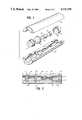
- FIG. 1 of the drawingsis an exploded view of an embodiment of this invention.
- FIG. 2 of the drawingsis a cross section of the same embodiment of this invention as set forth in FIG. 1.
- FIG. 3 of the drawingsis an exploded view of another embodiment of this invention.
- FIG. 4 of the drawingsis a cross section of the same embodiment of this invention as set forth in FIG. 3.
- FIGS. 1-4two specific embodiments, with the understanding that the present disclosure is not intended to limit the invention to the embodiments illustrated.
- FIGS. 1 and 2 of the drawingsillustrate a single embodiment of the optically pumped laser of this invention which has a substantially cylindrical configuration.
- FIG. 1is an exploded view of this embodiment, whereas FIG. 2 is a cross section.
- light from an optical pumping meanswhich consists of elements 1 and 2 is focused by lens 3 onto lasant material 4 which has a suitable reflective coating on surface 5 and is capable of being pumped by the light from said pumping means (1 and 2).
- the reflective coating on surface 5is highly transparent with respect to light produced by the pumping means (1 and 2) but is highly reflective with respect to light produced by the lasing of lasant material 4.
- Light emitted by the lasing of lasant material 4is passed through nonlinear optical material 6 to output coupler 7 which has a suitable reflective coating on surface 8 which is highly reflective with respect to light emitted by lasant material 4 but substantially transparent to frequency-modified light produced by nonlinear optical material 6.
- Output coupler 7is configured in such a manner that it serves to collimate the output radiation from the laser which passes through it.
- the support structure (9 and 10)is configured to receive the components and automatically arrange them with respect to one another along an optical path upon insertion into said support structure.
- Suitable optical pumping meansinclude, but are not limited to, laser diodes, light-emitting diodes and laser diode arrays, together with any ancillary packaging or structures.
- the term "optical pumping means”includes any heat sink or packaging associated with said laser diodes, light-emitting diodes and laser diode arrays but excludes any associated power supply.
- such devicesare commonly attached to a heat resistant and conductive heat sink and are packaged in a metal housing.
- a highly suitable optical pumping sourceconsists of a gallium aluminum arsenide laser diode 2 emitting light having a wavelength of about 810 nm, which is attached to heat sink 1.
- Heat sink 1can be passive in character.
- heat sink 1can also comprise a thermoelectric cooler to help maintain laser diode 2 at a constant temperature and thereby ensure optimal operation of laser diode 2. It will be appreciated, of course, that during operation the optical pumping means will be attached to a suitable power supply. Electrical leads from laser diode 2 which are directed to a power supply are not illustrated in FIGS. 1 and 2.
- Lens 3serves to focus light from laser diode 2 onto lasant material 4. This focusing results in a high pumping intensity and an associated high photon to photon conversion efficiency in lasant material 4.
- Any conventional optical means for focusing lightcan be used in place of simple lens 3.
- a gradient index lens, a ball lens, an aspheric lens or a combination of lensescan be utilized. It will be appreciated, however, that lens 3 is not essential to the laser of this invention and the use of such focusing means merely represents a preferred embodiment.
- Suitable lasant materialsinclude, but are not limited to, materials selected from the group consisting of glassy and crystalline host materials which are doped with an active material. Highly suitable active materials include, but are not limited to, ions of chromium, titanium and the rare earth metals.
- neodymium-doped YAGis a highly suitable lasant material 4 for use in combination with an optical pumping means which produces light having a wavelength of 810 nm. When pumped with light of this wavelength, neodymium-doped YAG can emit light having a wavelength of 1,064 nm.
- Lasant material 4is shown as a rod in FIGS. 1 and 2.
- the precise geometric shape of this componentcan vary widely.
- the lasant materialcan have lens-shaped surfaces or be rhombohedral in shape if desired.
- a preferred embodiment of the inventioninvolves the use of a fiber of lasant material which is end-pumped by the optical pumping means.
- Highly suitable fibers for this purposeinclude, but are not limited to, glass optical fibers which are doped with ions of a rare earth metal such as neodymium. The length of such a fiber is easily adjusted to result in absorption of essentially all of the light from the optical pumping means. If a very long fiber is required, it can be coiled, on a spool for example, in order to minimize the overall length of the laser of this invention.
- Lasant material 4has a reflective coating on surface 5.
- This coatingis conventional in character and is selected so that it transmits as much as possible of the incident pumping radiation from laser diode 2 while being highly reflective with respect to the radiation produced by lasing of lasant material 4.
- this coatingwill also be highly reflective of the second harmonic of the radiation produced by lasing of lasant material 4. High reflectivity of this second harmonic will serve to prevent the pump-side loss of any frequency doubled radiation which is produced by nonlinear optical material 6 upon reflection of light, which is not fequency doubled, back through nonlinear optical material 6 by the coating on surface 8.
- the coating on surface 5should be substantially transparent to said 810 nm light and highly reflective with respect to light having a wavelength of 1,064 nm. In a highly preferred embodiment, this coating will also be highly reflective of light having a wavelength of 532 nm, the second harmonic of the aforementioned 1,064 nm light. It will be appreciated, of course, that the wavelength selective mirror which is created by the coating on surface 5 need not be located on said surface. If desired, this mirror can be located anywhere between the optical pumping means and the lasant material, and can consist of a coating deposited on any suitable substrate. In addition, the mirror can be of any suitable shape.
- Nonlinear optical material 6Light emitted by the lasing of lasant material 4 is passed through nonlinear optical material 6.
- the frequency of the incident lightcan be modified, for example, doubled or tripled, by passage through nonlinear optical material 6.
- light having a wavelength of 1,064 nm from a neodymium-doped YAG lasant material 4can be converted to light having a wavelength of 532 nm upon passage through nonlinear optical material 6.
- nonlinear optical material 6is shown as a rod in FIGS. 1 and 2, it will be appreciated that the geometric shape of this component can vary widely.
- the nonlinear optical materialcan have lens-shaped surfaces or be rhombohedral in shape if desired. It will also be appreciated that any such nonlinear optical component can comprise heating or cooling means to control the temperature of said nonlinear optical material and thereby optimize its performance as a harmonic generator.
- Potassium titanyl phosphateis a highly preferred nonlinear optical material.
- any of the many known nonlinear optical materialscan be utilized in the practice of this invention.
- Such known nonlinear optical materialsinclude, but are not limited to, KH 2 PO 4 , LiNbO 3 , KNbO 3 , LiIO 3 , HIO 3 , KB 5 O 8 .4H 2 O, urea and compounds of the formula MTiO(XO 4 ) where M is selected from the group consisting of K, Rb and Tl, and X is selected from the group consisting of P and As.
- nonlinear optical material 6is not an essential laser component and its use merely represents one embodiment of this invention.
- nonlinear optical material 6is not 100 percent efficient as a second harmonic generator
- light passed through this component from lasant material 4will ordinarily consist of a mixture of frequency doubled light and unmodified light.
- the light passed through nonlinear optical material 6will be a mixture of 1,064 nm and 532 nm wavelengths. This mixture of wavelengths is directed to output coupler 7 which has a reflective coating on surface 8 which is wavelength selective.
- This coatingis conventional in character and is selected in such a manner that it is substantially transparent to the 532 nm light but highly reflective with respect to the 1,064 nm light. Accordingly, essentially only frequency doubled light having a wavelength of 532 nm is emitted through the output coupler.
- the wavelength selective mirror which is created by the coating on surface 8need not be of the precise design illustrated in FIGS. 1 and 2 and can be of any conventional form.
- the wavelength selective mirrorcan be created by a coating on surface 11 of nonlinear optical material 6.
- output coupler 7could be either eliminated or replaced by optical means whose sole purpose is to collimate or otherwise modify the output radiation from the laser.
- the concave shape of the mirror created by the coating on surface 8has the advantage of focusing reflected light, which has not been frequency doubled, back onto nonlinear optical material 6, through lasant material 4 and onto the coating on surface 5.
- this coating on surface 5is highly reflective of both frequency doubled and unmodified light from the lasing of lasant material 4.
- frequency-unmodified light reflected by the coating on surface 8is partially frequency doubled by passage through nonlinear optical material 6, the resulting mixture of wavelengths is reflected from the coating on surface 5 back through nonlinear optical material 6 where some of the residual frequency-unmodified light is frequency doubled, and the frequency doubled light is emitted through output coupler 7. Except for losses which may occur as a result of processes such as scattering or absorption, further repetition of this series of events results in essentially all of the light produced by the lasing of lasant material 4 being frequency doubled and emitted through output coupler 7.
- Support structure (9 and 10)is constructed with indentations in it which receive the various laser components and automatically arrange these components along an optical path upon their insertion.
- Each indentationis structured to receive a specific component but, otherwise, can be of any desired geometric shape.
- the indentationcan be a V-shaped or U-shaped groove of appropriate length.
- the support structureis preferably configured so that the laser components are arranged with respect to each other within predetermined tolerances upon insertion into support structure (9 and 10). If desired, these tolerances can be relatively large so that the components are arranged at substantially correct distances from each other with optimization of laser performance being achieved by empirical adjustment of the final spacing between the components.
- the componentscan be permanently fixed in place using conventional mechanical means, such as set screws, or conventional adhesives or bonding agents.
- a highly preferred embodiment of the inventioninvolves the use of a support structure which is configured so that the laser components are arranged in operative association with respect to one another along an optical path upon insertion into the support structure (9 and 10).
- the support structureis composed of two parts, 9 and 10, which fit together. These two parts can be bonded together using any conventional technique or combination of techniques. For example, parts 9 and 10 can be welded or bonded together with one or more adhesives or bonding agents. Alterntively, parts 9 and 10 can be bonded together by mechanical fastening means, such as snap type connecting means incorporated into the parts themselves.
- the support structure (9 and 10) illustrated in FIGS. 1 and 2forms a substantially tubular structure around the various laser components. It will be appreciated, however, that this is merely one embodiment of the invention, and the support structure of this invention can be of any convenient shape or configuration. For example, the support structure need not surround the laser components on all but two sides as shown in FIGS. 1 and 2. If desired, the support structure can be designed to form a substantially flat platform, a tray or a trough. It will be appreciated that the precise shape and configuration of the support structure will frequently be dictated by considerations of manufacturing convenience and intended use of the laser.
- the support structure of this inventioncan be composed of any suitable rigid material, such as metals, ceramics, glass, thermoplastic materials and thermosetting materials.
- the support structurecan be fabricated by any conventional technique.
- a metal support structurecan be fabricated by machining or die casting, and die cast aluminum support structures are particularly satisfactory.
- a highly preferred embodiment of the inventioninvolves the use of a support structure which is comprised of one or more thermoplastic materials.
- Suitable thermoplastic materialsinclude, but are not limited to, polyvinyl chloride, nylons, fluorocarbons, linear polyethylene, polyurethane prepolymer, polystyrene, polypropylene, and cellulosic and acrylic resins. If desired, composites of such thermoplastic materials with various fibers or other strengthening agents can also be employed.
- Thermoplastic and glass support structurescan be conveniently fabricated by injection molding techniques.
- the support structurecan be fabricated in two or more segments which are then assembled about the laser components.
- the optically pumped solid state laser of this inventioncan be of essentially any size, but is preferably very small.
- the overall length of the support structure containing the various laser componentsis desirably less than about 20 cm, preferably less than about 10 cm and more preferably less than about 5 cm.
- plasticsbecome highly suitable for use in constructing the support structure for the laser components. At these relatively small sizes, the relatively poor rigidity and thermal expansion properties of plastics are essentially irrelevant.
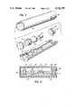
- FIGS. 3 and 4illustrate another single embodiment of the invention.
- FIG. 3is an exploded view of this embodiment, whereas FIG. 4 is a cross section.
- light from an optical pumping meanswhich consists of elements 20 and 21, is focused by lens 22 onto lasant material 23 which has a suitable reflective coating on surface 24 and is capable of being pumped by the light from said pumping means (20 and 21).
- the reflective coating on surface 24is highly transparent with respect to light from pumping means (20 and 21) but is highly reflective with respect to light produced by the lasing of lasant material 23.
- Light emitted by the lasing of lasant material 23is directed to output coupler 25 which has a suitable reflective coating on surface 26 and is configured to collimate the light passing through it.
- the reflective coating on surface 26is selected so that it will transmit some, but not all, of the light emitted by the lasing of lasant material 23.
- the coating on surface 26can have a reflectivity of about 95 percent with respect to the light emitted by lasant material 23.
- Suitable reflective coatings for use on surfaces 24 and 26are conventional in the art.
- Each of the laser components, optical pumping means (20 and 21), lens 22, lasant material 23 and output coupler 25fits into the support structure 27.
- the support structure 27is constructed with a unique identation for each laser component, with the indentations being appropriately spaced. Upon being fitted into these indentations, the various components are automatically arranged with respect to one another along an optical path. If desired, the various laser components can be permanently fixed in place after insertion into the support structure using conventional mechanical means or conventional adhesives or bonding agents.
- a substantially tubular housing 28fits around the support structure 27 and laser components (20 and 21), 22, 23 and 25.
- Housing 28is fitted with a flange 29 at one end and is adapted to receive an end plug 30 at the other end.
- End plug 30can be attached to housing 28 by welding or through the use of one or more adhesives or bonding agents.
- end plug 30can be attached to housing 28 by mechanical means.
- the plug 30 and housing 28can be provided with screw threads so that they can be screwed together and held together by the screw threads.
- the housing 28 and end plug 30can be composed of any suitable material. Such materials include, but are not limited to, metals, ceramics, thermoplastic materials and thermosetting materials.
- the optical pumping meansconsists of a heat sink 20 and a gallium aluminum arsenide diode laser 21 which emits light having a wavelength of 810 nm. Electrical leads from laser diode 21, which are directed to a power supply, are not illustrated in FIGS. 3 and 4. Light from laser diode 21 is focused by lens 22 onto a rod of neodymium-doped YAG 23 which emits light having a wavelength of 1,064 nm, and light of this wavelength is released from the laser through output coupler 25 in a collimated or otherwise appropriately divergent beam.
- FIGS. 3 and 4differs in that: (a) it does not utilize a nonlinear optical material [6 in FIGS. 1 and 2]; (b) the support structure in FIGS. 1 and 2 is fabricated in two segments, 9 and 10, whereas the support structure 27 of FIGS. 3 and 4 is composed of a single segment; and (c) a housing 28 is fitted around the support structure and laser components in FIGS. 3 and 4 but not in FIGS. 1 and 2.
Landscapes
- Physics & Mathematics (AREA)
- Electromagnetism (AREA)
- Engineering & Computer Science (AREA)
- Plasma & Fusion (AREA)
- Optics & Photonics (AREA)
- Microelectronics & Electronic Packaging (AREA)
- Lasers (AREA)
- Glass Compositions (AREA)
Abstract
Description
Claims (20)
Priority Applications (7)
| Application Number | Priority Date | Filing Date | Title |
|---|---|---|---|
| US06/879,157US4731795A (en) | 1986-06-26 | 1986-06-26 | Solid state laser |
| DE87305686TDE3787676T2 (en) | 1986-06-26 | 1987-06-25 | Solid state laser. |
| EP87305686AEP0251718B1 (en) | 1986-06-26 | 1987-06-25 | Solid state laser |
| AT87305686TATE95643T1 (en) | 1986-06-26 | 1987-06-25 | SOLID STATE LASER. |
| JP62159496AJPS6327079A (en) | 1986-06-26 | 1987-06-26 | Optical pumping laser |
| AU74743/87AAU7474387A (en) | 1986-06-26 | 1987-06-26 | Solid state laser |
| KR1019870006495AKR890001228A (en) | 1986-06-26 | 1987-06-26 | Solid state laser |
Applications Claiming Priority (1)
| Application Number | Priority Date | Filing Date | Title |
|---|---|---|---|
| US06/879,157US4731795A (en) | 1986-06-26 | 1986-06-26 | Solid state laser |
Publications (1)
| Publication Number | Publication Date |
|---|---|
| US4731795Atrue US4731795A (en) | 1988-03-15 |
Family
ID=25373551
Family Applications (1)
| Application Number | Title | Priority Date | Filing Date |
|---|---|---|---|
| US06/879,157Expired - LifetimeUS4731795A (en) | 1986-06-26 | 1986-06-26 | Solid state laser |
Country Status (7)
| Country | Link |
|---|---|
| US (1) | US4731795A (en) |
| EP (1) | EP0251718B1 (en) |
| JP (1) | JPS6327079A (en) |
| KR (1) | KR890001228A (en) |
| AT (1) | ATE95643T1 (en) |
| AU (1) | AU7474387A (en) |
| DE (1) | DE3787676T2 (en) |
Cited By (68)
| Publication number | Priority date | Publication date | Assignee | Title |
|---|---|---|---|---|
| US4884277A (en)* | 1988-02-18 | 1989-11-28 | Amoco Corporation | Frequency conversion of optical radiation |
| US4884281A (en)* | 1988-09-09 | 1989-11-28 | Spectra-Physics, Inc. | Low cost/power visible light solid-state laser |
| US4897850A (en)* | 1989-02-01 | 1990-01-30 | Amoco Corporation | Assembly for arranging optical components of a laser |
| US4907238A (en)* | 1989-06-26 | 1990-03-06 | United States Of America As Represented By The Secretary Of The Navy | Apparatus for the efficient wavelength conversion of laser radiation |
| US4933947A (en)* | 1988-02-18 | 1990-06-12 | Amoco Corporation | Frequency conversion of optical radiation |
| US4979180A (en)* | 1989-11-24 | 1990-12-18 | Muncheryan Arthur M | Modular interchangeable laser system |
| WO1991002275A1 (en)* | 1989-07-27 | 1991-02-21 | Dennis Craig Leiner | Disposable rigid endoscope |
| US5031182A (en)* | 1989-05-18 | 1991-07-09 | Amoco Corporation | Single-frequency laser of improved amplitude stability |
| US5042086A (en)* | 1988-11-16 | 1991-08-20 | Dylor Corporation | Method and means for transmitting large dynamic analog signals in optical fiber systems |
| US5043991A (en)* | 1989-12-28 | 1991-08-27 | General Dynamics Corp. Electronics Division | Device for compensating for thermal instabilities of laser diodes |
| US5062117A (en)* | 1990-07-11 | 1991-10-29 | Amoco Corporation | Tailored laser system |
| US5063566A (en)* | 1990-04-30 | 1991-11-05 | Amoco Corporation | Internally-doubled, composite-cavity microlaser |
| WO1992009127A1 (en)* | 1990-11-02 | 1992-05-29 | Massachusetts Institute Of Technology | A frequency-doubled, diode-pumped ytterbium laser |
| US5121404A (en)* | 1988-11-16 | 1992-06-09 | Hamamatsu Photonics K.K. | Optically pumped solid laser |
| US5121188A (en)* | 1990-05-16 | 1992-06-09 | Applied Laser Systems | Laser module assembly |
| US5121402A (en)* | 1990-09-28 | 1992-06-09 | The United State Of America As Represented By The Secretary Of The Navy | Multiple element ring laser |
| US5150376A (en)* | 1989-12-20 | 1992-09-22 | Matsushita Electric Indutrial Co., Ltd. | Laser source |
| US5216737A (en)* | 1991-02-28 | 1993-06-01 | U.S. Philips Corporation | Optoelectronic device comprising a semiconductor laser and an optical isolator |
| US5265114A (en)* | 1992-09-10 | 1993-11-23 | Electro Scientific Industries, Inc. | System and method for selectively laser processing a target structure of one or more materials of a multimaterial, multilayer device |
| US5381430A (en)* | 1993-04-27 | 1995-01-10 | Fuji Photo Film Co., Ltd. | Optical wavelength converting apparatus |
| US5394427A (en)* | 1994-04-29 | 1995-02-28 | Cutting Edge Optronics, Inc. | Housing for a slab laser pumped by a close-coupled light source |
| US5420876A (en)* | 1994-06-02 | 1995-05-30 | Spectra-Physics Laserplane, Inc. | Gadolinium vanadate laser |
| US5432811A (en)* | 1993-03-04 | 1995-07-11 | Tecnal Products, Inc. | Laser rod with polyhedron shaped ends |
| US5440574A (en)* | 1994-06-02 | 1995-08-08 | Spectra-Physics Laserplane, Inc. | Solid-state laser |
| US5450429A (en)* | 1994-06-02 | 1995-09-12 | Spectra-Physics Laserplane, Inc. | Efficient linear frequency doubled solid-state laser |
| WO1995034111A1 (en)* | 1994-06-02 | 1995-12-14 | Spectra-Physics Laserplane, Inc. | Solid-state laser with active etalon and method therefor |
| US5509226A (en)* | 1993-11-08 | 1996-04-23 | Lasermax Incorporated | Firearm with modified take down latch for controlling laser sight |
| US5511048A (en)* | 1991-01-04 | 1996-04-23 | Mitsubishi Denki Kabushiki Kaisha | Magneto-optical recording and reproducing apparatus |
| US5526373A (en)* | 1994-06-02 | 1996-06-11 | Karpinski; Arthur A. | Lens support structure for laser diode arrays |
| US5554153A (en)* | 1994-08-29 | 1996-09-10 | Cell Robotics, Inc. | Laser skin perforator |
| US5561684A (en)* | 1994-12-29 | 1996-10-01 | Santa Fe Laser Co., Inc. | Laser diode pumped solid state laser construction |
| US5668825A (en)* | 1994-06-02 | 1997-09-16 | Laser Diode Array, Inc. | Lens support structure for laser diode arrays |
| US5734669A (en)* | 1995-02-06 | 1998-03-31 | University Of Central Florida | 1.3 μm lasers using Nd3+ doped apatite crystals |
| DE19646072A1 (en)* | 1996-11-08 | 1998-05-14 | Daimler Benz Ag | Diode-pumped, frequency-doubled solid-state laser |
| US5808272A (en)* | 1994-11-22 | 1998-09-15 | Electro Scientific Industries, Inc. | Laser system for functional trimming of films and devices |
| US5848092A (en)* | 1994-12-28 | 1998-12-08 | Fuji Photo Film Co., Ltd. | Laser-diode-pumped solid state laser and method of manufacturing the same |
| US5870422A (en)* | 1997-07-09 | 1999-02-09 | Trw Inc. | Gain generator for high-energy chemical lasers |
| US6026109A (en)* | 1998-01-22 | 2000-02-15 | Cutting Edge Optronics, Inc. | High-power, solid-state laser in a cylindrical package |
| US6072815A (en)* | 1998-02-27 | 2000-06-06 | Litton Systems, Inc. | Microlaser submount assembly and associates packaging method |
| US6172997B1 (en) | 1998-06-16 | 2001-01-09 | Aculight Corporation | Integrated semiconductor diode laser pumped solid state laser |
| US6240113B1 (en) | 1998-02-27 | 2001-05-29 | Litton Systems, Inc. | Microlaser-based electro-optic system and associated fabrication method |
| US6373865B1 (en)* | 2000-02-01 | 2002-04-16 | John E. Nettleton | Pseudo-monolithic laser with an intracavity optical parametric oscillator |
| US6396649B1 (en)* | 1995-09-05 | 2002-05-28 | Aoti Operating Company, Inc. | Optical instruments |
| US20020105984A1 (en)* | 2000-12-15 | 2002-08-08 | The Furukawa Electric Co., Ltd. | Integrated laser beam synthesizing module for use in a semiconductor laser module and an optical amplifier |
| EP1054487A3 (en)* | 1999-05-14 | 2002-10-02 | Raytheon Company | Integrated lightweight optical bench and miniaturized laser transmitter using same |
| EP1211764A3 (en)* | 2000-10-31 | 2003-05-14 | Agilent Technologies, Inc. (a Delaware corporation) | System for optically pumping a long wavelength laser using a short wavelength laser |
| US6690687B2 (en)* | 2001-01-02 | 2004-02-10 | Spectrasensors, Inc. | Tunable semiconductor laser having cavity with ring resonator mirror and mach-zehnder interferometer |
| US20040057490A1 (en)* | 2002-09-23 | 2004-03-25 | Litton Systems, Inc. | Microlaser cavity assembly and associated packaging method |
| US20040101017A1 (en)* | 2002-11-21 | 2004-05-27 | Herron Michael Alan | Laser housing having integral mounts and method of manufacturing same |
| US20040258123A1 (en)* | 2003-06-23 | 2004-12-23 | Zamel James Michael | Diode-pumped solid-state laser gain module |
| US20050008047A1 (en)* | 2003-04-11 | 2005-01-13 | Sonhi Hashimoto | Laser system and laser wavelength conversion |
| US20050018742A1 (en)* | 2003-07-24 | 2005-01-27 | Hall Daniel F. | Cast laser optical bench |
| EP1507321A1 (en)* | 2003-08-11 | 2005-02-16 | Lumera Laser GmbH | Solid state laser pumped by a laser diode with a convergent beam |
| US20050163176A1 (en)* | 2004-01-26 | 2005-07-28 | Li-Ning You | Green diode laser |
| US20060171429A1 (en)* | 2005-01-28 | 2006-08-03 | Seitel Steven C | Monoblock laser with reflective substrate |
| US20060280221A1 (en)* | 2005-03-17 | 2006-12-14 | Seitel Steven C | Monoblock laser with improved alignment features |
| US20070258493A1 (en)* | 2006-05-02 | 2007-11-08 | Northrop Grumman Corporation | Laser power reduction without mode change |
| US20080063023A1 (en)* | 2006-06-05 | 2008-03-13 | Canon Kabushiki Kaisha | Optical scanning apparatus |
| US20090213894A1 (en)* | 2008-02-27 | 2009-08-27 | Ipg Photonics Corporation | Portable laser head |
| US7586958B2 (en) | 2006-09-29 | 2009-09-08 | Northrop Grumman Corporation | Electro-opto switching of unpolarized lasers |
| US7839904B1 (en) | 2006-01-26 | 2010-11-23 | Scientific Materials Corporation | Monoblock laser systems and methods |
| CN104854764A (en)* | 2012-10-17 | 2015-08-19 | Ipg光子公司 | Resonant Enhanced Frequency Converter |
| US20150249313A1 (en)* | 2012-10-17 | 2015-09-03 | Ipg Photonics Corporation | Resonant enhanced frequency converter |
| US20180233873A1 (en)* | 2017-02-16 | 2018-08-16 | University Of Pittsburgh - Of The Commonwealth System Of Higher Education | Laser system enabled by additive manufacturing |
| US20200251874A1 (en)* | 2019-01-31 | 2020-08-06 | L3Harris Technologies, Inc. | Continuous wave end-pumped laser |
| US11349274B2 (en) | 2018-10-16 | 2022-05-31 | Lumentum Operations Llc | Amplifier assembly |
| US11448866B2 (en) | 2019-03-19 | 2022-09-20 | Omek Optics Ltd. | Unit magnification microscope |
| US11552440B2 (en) | 2017-11-02 | 2023-01-10 | Leonardo UK Ltd | Laser |
Families Citing this family (11)
| Publication number | Priority date | Publication date | Assignee | Title |
|---|---|---|---|---|
| JPH02108016A (en)* | 1988-10-18 | 1990-04-19 | Hitachi Metals Ltd | Optical isolator |
| DE3836287A1 (en)* | 1988-10-25 | 1990-04-26 | Messerschmitt Boelkow Blohm | Solid-state laser |
| JPH02156583A (en)* | 1988-12-09 | 1990-06-15 | Asahi Glass Co Ltd | Laser diode pumped solid state laser |
| JPH02161786A (en)* | 1988-12-15 | 1990-06-21 | Hamamatsu Photonics Kk | Semiconductor laser excitation solid laser device |
| US5029335A (en)* | 1989-02-21 | 1991-07-02 | Amoco Corporation | Heat dissipating device for laser diodes |
| JPH033378A (en)* | 1989-05-31 | 1991-01-09 | Matsushita Electric Ind Co Ltd | solid state laser device |
| DE3925201A1 (en)* | 1989-07-29 | 1991-02-07 | Messerschmitt Boelkow Blohm | OPTICAL BENCH FOR MOUNTING OPTICAL, ELECTRICAL AND OTHERS COMPONENTS |
| JPH0443692A (en)* | 1990-06-11 | 1992-02-13 | Matsushita Electric Ind Co Ltd | Short wavelength laser light source and its implementation method |
| DE4303956C2 (en)* | 1993-02-10 | 1995-06-01 | Langner Walter | laser |
| DE4402668A1 (en)* | 1994-01-29 | 1995-08-03 | Frohn Hans Willi | Transversely pumped solid-state laser |
| DE19805849A1 (en)* | 1998-02-13 | 1999-09-02 | Daimler Chrysler Ag | Method for building and connecting optical components, in particular optical components in a laser resonator, and laser resonator used in this method |
Citations (6)
| Publication number | Priority date | Publication date | Assignee | Title |
|---|---|---|---|---|
| US4044315A (en)* | 1962-01-16 | 1977-08-23 | American Optical Corporation | Means for producing and amplifying optical energy |
| US4383318A (en)* | 1980-12-15 | 1983-05-10 | Hughes Aircraft Company | Laser pumping system |
| US4525842A (en)* | 1984-02-24 | 1985-06-25 | Myers John D | Laser device and method |
| US4546476A (en)* | 1982-12-10 | 1985-10-08 | The Board Of Trustees Of The Leland Stanford Junior University | Fiber optic amplifier |
| US4553238A (en)* | 1983-09-30 | 1985-11-12 | The Board Of Trustees Of The Leland Stanford University | Fiber optic amplifier |
| US4653056A (en)* | 1985-05-01 | 1987-03-24 | Spectra-Physics, Inc. | Nd-YAG laser |
Family Cites Families (6)
| Publication number | Priority date | Publication date | Assignee | Title |
|---|---|---|---|---|
| AT265701B (en)* | 1963-09-25 | 1968-10-25 | Meopta Narodni Podnik | Process for the production of optical or mechanical centered systems |
| US3753145A (en)* | 1972-06-26 | 1973-08-14 | Bell Telephone Labor Inc | Compact end-pumped solid-state laser |
| JPS5511363A (en)* | 1978-07-11 | 1980-01-26 | Nippon Telegr & Teleph Corp <Ntt> | Solid laser system |
| JPS57198671A (en)* | 1981-06-01 | 1982-12-06 | Toshiba Corp | Internal multiplication type higher harmonic light generating device |
| JPS6040093A (en)* | 1983-08-11 | 1985-03-02 | 蛇の目ミシン工業株式会社 | Dyeing sewing machine |
| JPS6182490A (en)* | 1984-09-29 | 1986-04-26 | Toshiba Corp | External reflector laser device |
- 1986
- 1986-06-26USUS06/879,157patent/US4731795A/ennot_activeExpired - Lifetime
- 1987
- 1987-06-25ATAT87305686Tpatent/ATE95643T1/ennot_activeIP Right Cessation
- 1987-06-25DEDE87305686Tpatent/DE3787676T2/ennot_activeExpired - Fee Related
- 1987-06-25EPEP87305686Apatent/EP0251718B1/ennot_activeExpired - Lifetime
- 1987-06-26JPJP62159496Apatent/JPS6327079A/enactivePending
- 1987-06-26KRKR1019870006495Apatent/KR890001228A/ennot_activeWithdrawn
- 1987-06-26AUAU74743/87Apatent/AU7474387A/ennot_activeAbandoned
Patent Citations (7)
| Publication number | Priority date | Publication date | Assignee | Title |
|---|---|---|---|---|
| US4044315A (en)* | 1962-01-16 | 1977-08-23 | American Optical Corporation | Means for producing and amplifying optical energy |
| US4383318A (en)* | 1980-12-15 | 1983-05-10 | Hughes Aircraft Company | Laser pumping system |
| US4546476A (en)* | 1982-12-10 | 1985-10-08 | The Board Of Trustees Of The Leland Stanford Junior University | Fiber optic amplifier |
| US4553238A (en)* | 1983-09-30 | 1985-11-12 | The Board Of Trustees Of The Leland Stanford University | Fiber optic amplifier |
| US4525842A (en)* | 1984-02-24 | 1985-06-25 | Myers John D | Laser device and method |
| US4653056A (en)* | 1985-05-01 | 1987-03-24 | Spectra-Physics, Inc. | Nd-YAG laser |
| US4653056B1 (en)* | 1985-05-01 | 1990-07-24 | Spectra Physics |
Non-Patent Citations (4)
| Title |
|---|
| Chester et al; "Min. Diode-Pumped Nd:YAIG Lasers"; Appl Phys Lett vol. 23, No. 5, Sep. 1, 1973. |
| Chester et al; Min. Diode Pumped Nd:YAIG Lasers ; Appl Phys Lett vol. 23, No. 5, Sep. 1, 1973.* |
| Washio et al; "Room-Temperature CW Operation of an Efficient Miniaturized Nd:YAG Laser End-Pumped by a Superlum. Diode"; Appl. Phys. Lett 29 (11); 1 Dec.'76. |
| Washio et al; Room Temperature CW Operation of an Efficient Miniaturized Nd:YAG Laser End Pumped by a Superlum. Diode ; Appl. Phys. Lett 29 (11); 1 Dec. 76.* |
Cited By (91)
| Publication number | Priority date | Publication date | Assignee | Title |
|---|---|---|---|---|
| US4933947A (en)* | 1988-02-18 | 1990-06-12 | Amoco Corporation | Frequency conversion of optical radiation |
| US4884277A (en)* | 1988-02-18 | 1989-11-28 | Amoco Corporation | Frequency conversion of optical radiation |
| US4884281A (en)* | 1988-09-09 | 1989-11-28 | Spectra-Physics, Inc. | Low cost/power visible light solid-state laser |
| US5121404A (en)* | 1988-11-16 | 1992-06-09 | Hamamatsu Photonics K.K. | Optically pumped solid laser |
| US5042086A (en)* | 1988-11-16 | 1991-08-20 | Dylor Corporation | Method and means for transmitting large dynamic analog signals in optical fiber systems |
| US4897850A (en)* | 1989-02-01 | 1990-01-30 | Amoco Corporation | Assembly for arranging optical components of a laser |
| WO1990009689A1 (en)* | 1989-02-01 | 1990-08-23 | Amoco Corporation | An assembly for arranging optical components of a laser |
| US5031182A (en)* | 1989-05-18 | 1991-07-09 | Amoco Corporation | Single-frequency laser of improved amplitude stability |
| US4907238A (en)* | 1989-06-26 | 1990-03-06 | United States Of America As Represented By The Secretary Of The Navy | Apparatus for the efficient wavelength conversion of laser radiation |
| WO1991002275A1 (en)* | 1989-07-27 | 1991-02-21 | Dennis Craig Leiner | Disposable rigid endoscope |
| US4979180A (en)* | 1989-11-24 | 1990-12-18 | Muncheryan Arthur M | Modular interchangeable laser system |
| US5150376A (en)* | 1989-12-20 | 1992-09-22 | Matsushita Electric Indutrial Co., Ltd. | Laser source |
| US5043991A (en)* | 1989-12-28 | 1991-08-27 | General Dynamics Corp. Electronics Division | Device for compensating for thermal instabilities of laser diodes |
| US5063566A (en)* | 1990-04-30 | 1991-11-05 | Amoco Corporation | Internally-doubled, composite-cavity microlaser |
| US5121188A (en)* | 1990-05-16 | 1992-06-09 | Applied Laser Systems | Laser module assembly |
| US5062117A (en)* | 1990-07-11 | 1991-10-29 | Amoco Corporation | Tailored laser system |
| US5121402A (en)* | 1990-09-28 | 1992-06-09 | The United State Of America As Represented By The Secretary Of The Navy | Multiple element ring laser |
| WO1992009127A1 (en)* | 1990-11-02 | 1992-05-29 | Massachusetts Institute Of Technology | A frequency-doubled, diode-pumped ytterbium laser |
| US5511048A (en)* | 1991-01-04 | 1996-04-23 | Mitsubishi Denki Kabushiki Kaisha | Magneto-optical recording and reproducing apparatus |
| US5216737A (en)* | 1991-02-28 | 1993-06-01 | U.S. Philips Corporation | Optoelectronic device comprising a semiconductor laser and an optical isolator |
| SG81853A1 (en)* | 1992-09-10 | 2001-07-24 | Electro Scient Ind Inc | System and method for selectively laser processing a target structure of one or more materials of a multimaterial, multilayer device |
| US5473624A (en)* | 1992-09-10 | 1995-12-05 | Electro Scientific Industries, Inc. | Laser system and method for selectively severing links |
| US5265114A (en)* | 1992-09-10 | 1993-11-23 | Electro Scientific Industries, Inc. | System and method for selectively laser processing a target structure of one or more materials of a multimaterial, multilayer device |
| US5432811A (en)* | 1993-03-04 | 1995-07-11 | Tecnal Products, Inc. | Laser rod with polyhedron shaped ends |
| US5381430A (en)* | 1993-04-27 | 1995-01-10 | Fuji Photo Film Co., Ltd. | Optical wavelength converting apparatus |
| US5509226A (en)* | 1993-11-08 | 1996-04-23 | Lasermax Incorporated | Firearm with modified take down latch for controlling laser sight |
| US5394427A (en)* | 1994-04-29 | 1995-02-28 | Cutting Edge Optronics, Inc. | Housing for a slab laser pumped by a close-coupled light source |
| US5420876A (en)* | 1994-06-02 | 1995-05-30 | Spectra-Physics Laserplane, Inc. | Gadolinium vanadate laser |
| US5668825A (en)* | 1994-06-02 | 1997-09-16 | Laser Diode Array, Inc. | Lens support structure for laser diode arrays |
| WO1995034111A1 (en)* | 1994-06-02 | 1995-12-14 | Spectra-Physics Laserplane, Inc. | Solid-state laser with active etalon and method therefor |
| US5450429A (en)* | 1994-06-02 | 1995-09-12 | Spectra-Physics Laserplane, Inc. | Efficient linear frequency doubled solid-state laser |
| US5526373A (en)* | 1994-06-02 | 1996-06-11 | Karpinski; Arthur A. | Lens support structure for laser diode arrays |
| US5440574A (en)* | 1994-06-02 | 1995-08-08 | Spectra-Physics Laserplane, Inc. | Solid-state laser |
| US5479431A (en)* | 1994-06-02 | 1995-12-26 | Spectra-Physics Laserplane, Inc. | Solid-state laser with active etalon and method therefor |
| US5908416A (en)* | 1994-08-29 | 1999-06-01 | Cell Robotics, Inc. | Laser dermal perforator |
| US5554153A (en)* | 1994-08-29 | 1996-09-10 | Cell Robotics, Inc. | Laser skin perforator |
| US5808272A (en)* | 1994-11-22 | 1998-09-15 | Electro Scientific Industries, Inc. | Laser system for functional trimming of films and devices |
| US5848092A (en)* | 1994-12-28 | 1998-12-08 | Fuji Photo Film Co., Ltd. | Laser-diode-pumped solid state laser and method of manufacturing the same |
| US5561684A (en)* | 1994-12-29 | 1996-10-01 | Santa Fe Laser Co., Inc. | Laser diode pumped solid state laser construction |
| US5734669A (en)* | 1995-02-06 | 1998-03-31 | University Of Central Florida | 1.3 μm lasers using Nd3+ doped apatite crystals |
| US6396649B1 (en)* | 1995-09-05 | 2002-05-28 | Aoti Operating Company, Inc. | Optical instruments |
| DE19646072A1 (en)* | 1996-11-08 | 1998-05-14 | Daimler Benz Ag | Diode-pumped, frequency-doubled solid-state laser |
| US5870422A (en)* | 1997-07-09 | 1999-02-09 | Trw Inc. | Gain generator for high-energy chemical lasers |
| US6026109A (en)* | 1998-01-22 | 2000-02-15 | Cutting Edge Optronics, Inc. | High-power, solid-state laser in a cylindrical package |
| US6240113B1 (en) | 1998-02-27 | 2001-05-29 | Litton Systems, Inc. | Microlaser-based electro-optic system and associated fabrication method |
| US6072815A (en)* | 1998-02-27 | 2000-06-06 | Litton Systems, Inc. | Microlaser submount assembly and associates packaging method |
| US6292499B1 (en) | 1998-06-16 | 2001-09-18 | Aculight Corporation | Solderable optical mount |
| US6172997B1 (en) | 1998-06-16 | 2001-01-09 | Aculight Corporation | Integrated semiconductor diode laser pumped solid state laser |
| EP1054487A3 (en)* | 1999-05-14 | 2002-10-02 | Raytheon Company | Integrated lightweight optical bench and miniaturized laser transmitter using same |
| US6556614B2 (en)* | 2000-02-01 | 2003-04-29 | John E. Nettleton | Monolithic solid state laser assembly and method of manufacture |
| US6373865B1 (en)* | 2000-02-01 | 2002-04-16 | John E. Nettleton | Pseudo-monolithic laser with an intracavity optical parametric oscillator |
| EP1211764A3 (en)* | 2000-10-31 | 2003-05-14 | Agilent Technologies, Inc. (a Delaware corporation) | System for optically pumping a long wavelength laser using a short wavelength laser |
| US20020105984A1 (en)* | 2000-12-15 | 2002-08-08 | The Furukawa Electric Co., Ltd. | Integrated laser beam synthesizing module for use in a semiconductor laser module and an optical amplifier |
| US6690687B2 (en)* | 2001-01-02 | 2004-02-10 | Spectrasensors, Inc. | Tunable semiconductor laser having cavity with ring resonator mirror and mach-zehnder interferometer |
| US6891879B2 (en)* | 2002-09-23 | 2005-05-10 | Litton Systems, Inc. | Microlaser cavity assembly and associated packaging method |
| US20040057490A1 (en)* | 2002-09-23 | 2004-03-25 | Litton Systems, Inc. | Microlaser cavity assembly and associated packaging method |
| US20040101017A1 (en)* | 2002-11-21 | 2004-05-27 | Herron Michael Alan | Laser housing having integral mounts and method of manufacturing same |
| US6807219B2 (en)* | 2002-11-21 | 2004-10-19 | Honeywell Federal Manufacturing & Technologies | Laser housing having integral mounts and method of manufacturing same |
| US20050008047A1 (en)* | 2003-04-11 | 2005-01-13 | Sonhi Hashimoto | Laser system and laser wavelength conversion |
| US7170919B2 (en) | 2003-06-23 | 2007-01-30 | Northrop Grumman Corporation | Diode-pumped solid-state laser gain module |
| US20040258123A1 (en)* | 2003-06-23 | 2004-12-23 | Zamel James Michael | Diode-pumped solid-state laser gain module |
| US20050018742A1 (en)* | 2003-07-24 | 2005-01-27 | Hall Daniel F. | Cast laser optical bench |
| US7495848B2 (en) | 2003-07-24 | 2009-02-24 | Northrop Grumman Corporation | Cast laser optical bench |
| US7876802B2 (en) | 2003-08-11 | 2011-01-25 | Lumera Laser Gmbh | High gain tapered laser gain module |
| US20050036532A1 (en)* | 2003-08-11 | 2005-02-17 | Mcdonagh Louis | High gain tapered laser gain module |
| EP1507321A1 (en)* | 2003-08-11 | 2005-02-16 | Lumera Laser GmbH | Solid state laser pumped by a laser diode with a convergent beam |
| US20050163176A1 (en)* | 2004-01-26 | 2005-07-28 | Li-Ning You | Green diode laser |
| US7003006B2 (en)* | 2004-01-26 | 2006-02-21 | Li-Ning You | Green diode laser |
| US7729392B2 (en) | 2005-01-28 | 2010-06-01 | Scientific Materials Corporation | Monoblock laser with reflective substrate |
| US20060171429A1 (en)* | 2005-01-28 | 2006-08-03 | Seitel Steven C | Monoblock laser with reflective substrate |
| US7817704B2 (en)* | 2005-03-17 | 2010-10-19 | Scientific Materials Corporation | Monoblock laser with improved alignment features |
| US20060280221A1 (en)* | 2005-03-17 | 2006-12-14 | Seitel Steven C | Monoblock laser with improved alignment features |
| US7839904B1 (en) | 2006-01-26 | 2010-11-23 | Scientific Materials Corporation | Monoblock laser systems and methods |
| US20070258493A1 (en)* | 2006-05-02 | 2007-11-08 | Northrop Grumman Corporation | Laser power reduction without mode change |
| US7460566B2 (en) | 2006-05-02 | 2008-12-02 | Northrop Grumman Corporation | Laser power reduction without mode change |
| US7508859B2 (en)* | 2006-06-05 | 2009-03-24 | Canon Kabushiki Kaisha | Optical scanning apparatus |
| US20080063023A1 (en)* | 2006-06-05 | 2008-03-13 | Canon Kabushiki Kaisha | Optical scanning apparatus |
| US7586958B2 (en) | 2006-09-29 | 2009-09-08 | Northrop Grumman Corporation | Electro-opto switching of unpolarized lasers |
| US20090213894A1 (en)* | 2008-02-27 | 2009-08-27 | Ipg Photonics Corporation | Portable laser head |
| US7653116B2 (en)* | 2008-02-27 | 2010-01-26 | Ipg Photonics Corporation | Portable laser head |
| CN104854764A (en)* | 2012-10-17 | 2015-08-19 | Ipg光子公司 | Resonant Enhanced Frequency Converter |
| US20150249313A1 (en)* | 2012-10-17 | 2015-09-03 | Ipg Photonics Corporation | Resonant enhanced frequency converter |
| US10209604B2 (en)* | 2012-10-17 | 2019-02-19 | Ipg Photonics Corporation | Resonant enhanced frequency converter |
| US20180233873A1 (en)* | 2017-02-16 | 2018-08-16 | University Of Pittsburgh - Of The Commonwealth System Of Higher Education | Laser system enabled by additive manufacturing |
| US10811835B2 (en)* | 2017-02-16 | 2020-10-20 | University Of Pittsburgh-Of The Commonwealth System Of Higher Education | Laser system enabled by additive manufacturing |
| US11552440B2 (en) | 2017-11-02 | 2023-01-10 | Leonardo UK Ltd | Laser |
| US11349274B2 (en) | 2018-10-16 | 2022-05-31 | Lumentum Operations Llc | Amplifier assembly |
| US11894651B2 (en) | 2018-10-16 | 2024-02-06 | Lumentum Operations Llc | Amplifier assembly |
| US20200251874A1 (en)* | 2019-01-31 | 2020-08-06 | L3Harris Technologies, Inc. | Continuous wave end-pumped laser |
| US11881676B2 (en)* | 2019-01-31 | 2024-01-23 | L3Harris Technologies, Inc. | End-pumped Q-switched laser |
| US11448866B2 (en) | 2019-03-19 | 2022-09-20 | Omek Optics Ltd. | Unit magnification microscope |
Also Published As
| Publication number | Publication date |
|---|---|
| KR890001228A (en) | 1989-03-20 |
| EP0251718B1 (en) | 1993-10-06 |
| EP0251718A2 (en) | 1988-01-07 |
| ATE95643T1 (en) | 1993-10-15 |
| DE3787676D1 (en) | 1993-11-11 |
| EP0251718A3 (en) | 1989-03-29 |
| DE3787676T2 (en) | 1994-05-05 |
| JPS6327079A (en) | 1988-02-04 |
| AU7474387A (en) | 1988-01-07 |
Similar Documents
| Publication | Publication Date | Title |
|---|---|---|
| US4731795A (en) | Solid state laser | |
| US4730335A (en) | Solid state laser and method of making | |
| US5802086A (en) | Single cavity solid state laser with intracavity optical frequency mixing | |
| EP0715774B1 (en) | Deep blue microlaser | |
| US5623510A (en) | Tunable, diode side-pumped Er: YAG laser | |
| US4847851A (en) | Butt-coupled single transverse mode diode pumped laser | |
| US4713822A (en) | Laser device | |
| US4701929A (en) | Laser diode pumped solid state laser | |
| US5530711A (en) | Low threshold diode-pumped tunable dye laser | |
| US4890289A (en) | Fiber coupled diode pumped moving solid state laser | |
| US4756003A (en) | Laser diode pumped solid state laser | |
| US4808789A (en) | Diode-pumped-laser instrumentation system | |
| US5485482A (en) | Method for design and construction of efficient, fundamental transverse mode selected, diode pumped, solid state lasers | |
| US4916712A (en) | Optically pumped slab laser | |
| GB2184596A (en) | Laser diode pumped solid state laser | |
| US4945544A (en) | Diode laser pumped solid-state laser | |
| GB2218845A (en) | Nd-yag laser | |
| JPH0621539A (en) | Laser system | |
| EP0422834B1 (en) | Simultaneous generation of laser radiation at two different frequencies | |
| US6778563B2 (en) | Q-switched laser | |
| US6914928B2 (en) | Diode array end pumped slab laser | |
| US6512630B1 (en) | Miniature laser/amplifier system | |
| EP0078941A1 (en) | Light-emitting-diode-pumped alexandrite laser | |
| JPH02185082A (en) | Laser die auto-pumped solid-state laser | |
| WO1994029937A2 (en) | Blue microlaser |
Legal Events
| Date | Code | Title | Description |
|---|---|---|---|
| AS | Assignment | Owner name:AMOCO CORPORATION, CHICAGO, IL., A CORP OF IN. Free format text:ASSIGNMENT OF ASSIGNORS INTEREST.;ASSIGNORS:CLARK, JOHN H.;WERTH, DENNIS L.;REEL/FRAME:004582/0157 Effective date:19860625 Owner name:AMOCO CORPORATION,ILLINOIS Free format text:ASSIGNMENT OF ASSIGNORS INTEREST;ASSIGNORS:CLARK, JOHN H.;WERTH, DENNIS L.;REEL/FRAME:004582/0157 Effective date:19860625 | |
| STCF | Information on status: patent grant | Free format text:PATENTED CASE | |
| CC | Certificate of correction | ||
| FPAY | Fee payment | Year of fee payment:4 | |
| FEPP | Fee payment procedure | Free format text:PAYOR NUMBER ASSIGNED (ORIGINAL EVENT CODE: ASPN); ENTITY STATUS OF PATENT OWNER: LARGE ENTITY | |
| FPAY | Fee payment | Year of fee payment:8 | |
| AS | Assignment | Owner name:ATX TELECOM SYSTEMS, INC., ILLINOIS Free format text:ASSIGNMENT OF ASSIGNORS INTEREST;ASSIGNOR:AMOCO CORPORATION;REEL/FRAME:008104/0178 Effective date:19960625 | |
| FPAY | Fee payment | Year of fee payment:12 | |
| AS | Assignment | Owner name:SCIENTIFIC-ATLANTA, INC., GEORGIA Free format text:MERGER;ASSIGNOR:ATX TELECOM SYSTEMS, INC.;REEL/FRAME:016004/0887 Effective date:19980624 |