US4731055A - Blood flow conduit - Google Patents
Blood flow conduitDownload PDFInfo
- Publication number
- US4731055A US4731055AUS06/899,624US89962486AUS4731055AUS 4731055 AUS4731055 AUS 4731055AUS 89962486 AUS89962486 AUS 89962486AUS 4731055 AUS4731055 AUS 4731055A
- Authority
- US
- United States
- Prior art keywords
- tube
- balloons
- blood flow
- flow conduit
- end portions
- Prior art date
- Legal status (The legal status is an assumption and is not a legal conclusion. Google has not performed a legal analysis and makes no representation as to the accuracy of the status listed.)
- Expired - Lifetime
Links
- 230000017531blood circulationEffects0.000titleclaimsabstractdescription36
- 210000004204blood vesselAnatomy0.000claimsabstractdescription12
- 238000003780insertionMethods0.000claimsabstractdescription9
- 230000037431insertionEffects0.000claimsabstractdescription9
- 230000000541pulsatile effectEffects0.000claimsabstractdescription5
- 229920001296polysiloxanePolymers0.000claimsdescription22
- 238000004891communicationMethods0.000claimsdescription9
- 230000000007visual effectEffects0.000claimsdescription5
- 230000006378damageEffects0.000claimsdescription4
- 208000014674injuryDiseases0.000claimsdescription2
- 239000012530fluidSubstances0.000claims6
- 208000027418Wounds and injuryDiseases0.000claims1
- 210000004369bloodAnatomy0.000description15
- 239000008280bloodSubstances0.000description15
- 238000000034methodMethods0.000description12
- FAPWRFPIFSIZLT-UHFFFAOYSA-MSodium chlorideChemical compound[Na+].[Cl-]FAPWRFPIFSIZLT-UHFFFAOYSA-M0.000description7
- 210000001168carotid artery commonAnatomy0.000description7
- 239000011780sodium chlorideSubstances0.000description5
- 239000000853adhesiveSubstances0.000description4
- 230000001070adhesive effectEffects0.000description4
- 238000013171endarterectomyMethods0.000description4
- KFZMGEQAYNKOFK-UHFFFAOYSA-NIsopropanolChemical compoundCC(C)OKFZMGEQAYNKOFK-UHFFFAOYSA-N0.000description3
- 239000004809TeflonSubstances0.000description3
- 229920006362Teflon®Polymers0.000description3
- 230000000740bleeding effectEffects0.000description3
- 210000004004carotid artery internalAnatomy0.000description3
- 238000013172carotid endarterectomyMethods0.000description3
- 238000004519manufacturing processMethods0.000description3
- 210000000601blood cellAnatomy0.000description2
- 238000010276constructionMethods0.000description2
- 238000001125extrusionMethods0.000description2
- 239000000463materialSubstances0.000description2
- 238000012986modificationMethods0.000description2
- 230000004048modificationEffects0.000description2
- 238000012544monitoring processMethods0.000description2
- 238000010926purgeMethods0.000description2
- 238000001356surgical procedureMethods0.000description2
- 125000000391vinyl groupChemical group[H]C([*])=C([H])[H]0.000description2
- 229920002554vinyl polymerPolymers0.000description2
- 206010001526Air embolismDiseases0.000description1
- JOYRKODLDBILNP-UHFFFAOYSA-NEthyl urethaneChemical compoundCCOC(N)=OJOYRKODLDBILNP-UHFFFAOYSA-N0.000description1
- 239000004677NylonSubstances0.000description1
- 230000000903blocking effectEffects0.000description1
- 230000036772blood pressureEffects0.000description1
- 238000010241blood samplingMethods0.000description1
- 230000009172burstingEffects0.000description1
- 210000001715carotid arteryAnatomy0.000description1
- 210000000269carotid artery externalAnatomy0.000description1
- 239000003795chemical substances by applicationSubstances0.000description1
- 230000003467diminishing effectEffects0.000description1
- 238000006073displacement reactionMethods0.000description1
- 239000003814drugSubstances0.000description1
- 229940079593drugDrugs0.000description1
- 229920001971elastomerPolymers0.000description1
- 239000000806elastomerSubstances0.000description1
- 239000003292glueSubstances0.000description1
- 229920000126latexPolymers0.000description1
- 239000004816latexSubstances0.000description1
- 230000001050lubricating effectEffects0.000description1
- 239000000203mixtureSubstances0.000description1
- 229920001778nylonPolymers0.000description1
- 238000007789sealingMethods0.000description1
- 229920002725thermoplastic elastomerPolymers0.000description1
- 229920002803thermoplastic polyurethanePolymers0.000description1
- 230000008733traumaEffects0.000description1
- XLYOFNOQVPJJNP-UHFFFAOYSA-NwaterSubstancesOXLYOFNOQVPJJNP-UHFFFAOYSA-N0.000description1
Images


Classifications
- A—HUMAN NECESSITIES
- A61—MEDICAL OR VETERINARY SCIENCE; HYGIENE
- A61B—DIAGNOSIS; SURGERY; IDENTIFICATION
- A61B17/00—Surgical instruments, devices or methods
- A61B17/12—Surgical instruments, devices or methods for ligaturing or otherwise compressing tubular parts of the body, e.g. blood vessels or umbilical cord
- A61B17/12022—Occluding by internal devices, e.g. balloons or releasable wires
- A61B17/12027—Type of occlusion
- A61B17/1204—Type of occlusion temporary occlusion
- A61B17/12045—Type of occlusion temporary occlusion double occlusion, e.g. during anastomosis
- A—HUMAN NECESSITIES
- A61—MEDICAL OR VETERINARY SCIENCE; HYGIENE
- A61B—DIAGNOSIS; SURGERY; IDENTIFICATION
- A61B17/00—Surgical instruments, devices or methods
- A61B17/11—Surgical instruments, devices or methods for performing anastomosis; Buttons for anastomosis
- A—HUMAN NECESSITIES
- A61—MEDICAL OR VETERINARY SCIENCE; HYGIENE
- A61B—DIAGNOSIS; SURGERY; IDENTIFICATION
- A61B17/00—Surgical instruments, devices or methods
- A61B17/12—Surgical instruments, devices or methods for ligaturing or otherwise compressing tubular parts of the body, e.g. blood vessels or umbilical cord
- A61B17/12022—Occluding by internal devices, e.g. balloons or releasable wires
- A61B17/12099—Occluding by internal devices, e.g. balloons or releasable wires characterised by the location of the occluder
- A61B17/12109—Occluding by internal devices, e.g. balloons or releasable wires characterised by the location of the occluder in a blood vessel
- A—HUMAN NECESSITIES
- A61—MEDICAL OR VETERINARY SCIENCE; HYGIENE
- A61B—DIAGNOSIS; SURGERY; IDENTIFICATION
- A61B17/00—Surgical instruments, devices or methods
- A61B17/12—Surgical instruments, devices or methods for ligaturing or otherwise compressing tubular parts of the body, e.g. blood vessels or umbilical cord
- A61B17/12022—Occluding by internal devices, e.g. balloons or releasable wires
- A61B17/12131—Occluding by internal devices, e.g. balloons or releasable wires characterised by the type of occluding device
- A61B17/12136—Balloons
- A—HUMAN NECESSITIES
- A61—MEDICAL OR VETERINARY SCIENCE; HYGIENE
- A61F—FILTERS IMPLANTABLE INTO BLOOD VESSELS; PROSTHESES; DEVICES PROVIDING PATENCY TO, OR PREVENTING COLLAPSING OF, TUBULAR STRUCTURES OF THE BODY, e.g. STENTS; ORTHOPAEDIC, NURSING OR CONTRACEPTIVE DEVICES; FOMENTATION; TREATMENT OR PROTECTION OF EYES OR EARS; BANDAGES, DRESSINGS OR ABSORBENT PADS; FIRST-AID KITS
- A61F2/00—Filters implantable into blood vessels; Prostheses, i.e. artificial substitutes or replacements for parts of the body; Appliances for connecting them with the body; Devices providing patency to, or preventing collapsing of, tubular structures of the body, e.g. stents
- A61F2/02—Prostheses implantable into the body
- A61F2/04—Hollow or tubular parts of organs, e.g. bladders, tracheae, bronchi or bile ducts
- A61F2/06—Blood vessels
- A—HUMAN NECESSITIES
- A61—MEDICAL OR VETERINARY SCIENCE; HYGIENE
- A61B—DIAGNOSIS; SURGERY; IDENTIFICATION
- A61B17/00—Surgical instruments, devices or methods
- A61B17/12—Surgical instruments, devices or methods for ligaturing or otherwise compressing tubular parts of the body, e.g. blood vessels or umbilical cord
- A61B17/12022—Occluding by internal devices, e.g. balloons or releasable wires
- A61B2017/12127—Double occlusion, e.g. for creating blood-free anastomosis site
Definitions
- This inventionrelates generally to surgical apparatus and the manufacture thereof and, more particularly, to a conduit for transporting blood between blood vessels during surgical procedures without significant blood loss and without the need for potentially damaging and difficult to use clamps or ties for attaching the conduit to the vessels.
- U.S. Pat. No. 3,435,824describes a surgical apparatus which may be used in by-passing an arterial vessel so that the flow of blood can continue while a diseased section of the vessel is corrected.
- the apparatusincludes a tube with a continuous axially disposed bore and inflatable means encircling the end portions of the tube for maintaining the tube in position within the circulatory system.
- the shunt describedcomprises a soft silicone tube equipped with silicone balloons at both ends which are inflated to hold the tube in place during the endarterectomy procedure while preventing bleeding from the gap between the tube and the inner surface of the carotid arteries.
- Other double balloon shuntsare commercially available using a rigid vinyl tube instead of the silicone tube used by Furui and Hasuo.
- a further object of the present inventionis to provide a blood flow conduit with inflatable balloons at its ends, which is resilient along most of its length yet will not collapse upon application of excessive pressure to the balloons.
- Yet another object of the present inventionis to provide a blood flow conduit which includes an elongated branch for indwelling intraluminal application to the common carotid artery in performing a carotid endarterectomy.
- a still further object of the present inventionis to provide a blood flow conduit with pressure sensing means which provide a tactile indication of the pulsatile flow of blood in the conduit.
- Another object of the present inventionis to provide an improved method for manufacturing a blood flow conduit with balloons at either end which may be inflated for intraluminal attachment to blood vessels.
- the present inventionis therefore directed to a blood flow conduit including a resilient tube having at least two end portions provided with external inflatable balloons encircling the tube adjacent the end portions and bushings positioned within the resilient tube below the inflatable balloons.
- the inventionis directed to a blood flow conduit which includes an longated end with an enlarged balloon which is particularly well adapted for attachment to the common carotid artery.
- the inventionis directed to a blood flow conduit having end portions provided with external inflatable balloons and means for providing a tactile and visual indication of the pulsatile flow of blood flow in the conduit.
- the inventionis directed to a blood flow conduit of the type generally described, in which means are provided for tactilely and visually indicating when excessive pressure is applied to the intraluminal balloons.
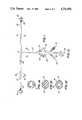
- FIG. 1is a front elevation view of a blood flow conduit in accordance with the present invention
- FIGS. 1A and 1Bare cross sectional views, taken on section lines 1A--1A and 1B--1B of FIG. 1, showing in an enlarged cross-sectional view the position of the inflation lumens in the apparatus of the invention;
- FIG. 1Cis a fragmentary front elevation view of an alternative embodiment of the invention in which the inflation tube of the apparatus of the invention includes a large central lumen in communication with the blood carrying branches of the blood flow conduit of the invention and FIG. 1D is a cross-sectional view of the inflation tube;
- FIG. 2is an alternative of the embodiment of the invention in which a bushing is positioned below the inflatable balloon of the embodiment of FIG. 1 and FIG. 2A is a cross-sectional view thereof taken along section lines 2A--2A;
- FIG. 3is a front elevation view of an alternative embodiment of the invention depicting means for sensing the application of excessive pressure on intraluminal balloons of the device;
- FIGS. 4A-Care front elevation views depicting a preferred method of constructing the apparatus of FIGS. 1 and 1C.
- FIG. 1there is illustrated a blood flow conduit 10 constructed in accordance with the present invention, comprising silicone tube 11 including a a common carotid branch 12 and an internal carotid branch 14 with respective common carotid balloon 16 and internal carotid balloon 18 (balloons inflated for illustration purposes).
- common carotid branch 12 and common carotid balloon 16are enlarged to permit a deeper fit with greater contact area in the common carotid artery in order to more effectively control the escape of blood under the higher blood pressure present in the common carotid artery during the endarterectomy procedure.
- Balloons 16 and 18comprise flexible silicone collars integrally bonded to their respective branches of tube 11 in a conventional fashion using silicone room temperature vulcanizing ("RTV") adhesive.
- An inflation lumen 20 formed in a conventional extrusion processruns along the wall of tube 11 in each of the conduit branches, as best seen in the cross-sectional view of FIG. 1A.
- An inflation tube 22is joined to the tube 11 at the intersection of branches 12 and 14.
- Inflation lumens 24 and 26 (FIG. 1B) of the inflation tubecommunicate with balloons 16 and 18 through their respective portions of inflation lumen 20 and with conventional syringe activated valves 28 and 30 located near the proximal end of the inflation tube.
- the valvesare color-coded, at 32 and 34, to corresponding color bands 32' and 34' adjacent the inner edge of the balloons.
- the surgeoncan inflate the desired balloon by introducing by way of a syringe a pressure medium such as saline through the appropriate color-coded syringe valve in communication with that balloon.
- the markings adjacent the balloonsalso serve to alert the surgeon when he is working in their vicinity to thereby minimize the danger that he will inadvertently puncture a balloon.
- inflation tube 22 of FIG. 1may be replaced by an alternate inflation tube 36 having a large central lumen 38 in communication with the blood carrying branches 12 and 14 of tube 11 as illustrated in FIGS. 1C and 1D.
- Tube 36is provided with a stopcock 40 which may be affixed to the tube as shown with a shrink band 42.
- Tube 36acts as an access port for the introduction of drugs into the blood flowing in tube 11, for the attachment of devices for continuously monitoring pressure in the system, or for blood sampling.
- Branches 12 and 14 of tube 11have depth markings 44 spaced every five centimeters to give the surgeon an indication of the depth of insertion of the branch in the blood vessel. These depth markings are preferably color coordinated with the band markings 32' and 34' at the balloons to identify the branch with its respective valve and balloon.
- FIGS. 2 and 2Athere is illustrated an important embodiment of the invention in which a rigid 46 is positioned within the lumen of branch 12 to facilitate insertion of the end of the branch into a blood vessel.
- the rigid tubeis offset from the end of the soft rounded end of the branch leaving a resilient silicone edge 48 to lead the way into vessel with minimal disturbance of arterial plaque and minimal interruption of the vessel wall.
- This rigid bushingnot only aids in the insertion procedure, it also serves the most important role of preventing collapse of the lumen in case excessive pressure is applied to balloon 16. Although illustrated only with respect to branch 12 and balloon 16, the rigid bushing may be applied to the other branch and balloon to achieve like advantages there.
- Branches 12 and 14 and inflation tubes 22 or 36may be constructed of silicone having the proper durometer, wall thickness and lumen diameter to permit a visually and tactilely observable flexure responsive to the pulsatile flow of the blood through tube 11 to visually and tactilely assure the surgeon that blood is flowing as intended.
- extra resilient sectionsmay be provided in the branches near the point of attachment to tubes 22 or 36 to give more localized such indications.
- indicator balloons 50 and 52are affixed to the inflation tube in communication with the inflation lumens corresponding to balloons 16 and 18 to provide a visual and tactile indication to the surgeon of the pressure in the interluminally positioned balloons 16 and 18 as they are being inflated.
- the indicator balloonsmay be constructed of a silicone of the proper durometer and thickness such that they begin inflating when the appropriate pressure threshold or maximum desirable pressure of balloons 14 and 18 is exceeded, thereby providing not only an indication of the balloon inflation, but a means of relieving excess intraluminal balloon pressure, diminishing the possibility of resulting vessel damage or bursting of the intraluminal balloons due to over-inflation.
- Balloons 50 and 52may alternatively be positioned on the branches 12 and 14 of tube 11.
- FIGS. 4A, 4B and 4Ca particularly convenient method for construction of the conduit of the present invention is illustrated.
- the constructionuses tubing having an integral inflation lumen 60 along its entire length, constructed by conventional extrusion techniques. A portion of the tubing, 62, is laid out on a glue rack (not shown) and notches 64 and 66 are cut into the tube near either end thereof, above the inflation lumen. Silicone balloons are then affixed over these notches by conventional means such as with the use of silicone RTV adhesive (FIG. 4C).
- notches 68 and 70are cut into the wall of tube 62 providing further openings to the inflation lumen. Notches 64-70 are of approximately the same size. Finally, an enlarged opening 72 is cut into tube 62 bisecting the inflation lumen and communicating with the central lumen 74 of tube 62.
- Another silicone tube 76 having two integral inflation lumens 78 and 80 along its opposite edgesis positioned perpendicularly to tube 62, with its distal end opposite opening 72 and with notches 66 and 68 on either side of tube 76, opposite the inflation lumens in the tube.
- a teflon rod 82is passed through tube 76 so that is protrudes slightly into lumen 74 of tube 62 through opening 72.
- a section of silicone tubing 84(without inflation lumens) is passed over the proximal end of the teflon rod until it abuts the proximal end of tube 76, and funnels 86 and 88 which will be later used to assemble the balloon syringe valves are positioned adjacent the spacing between tubes 76 and 84, with the funnel openings opposite the respective inflation lumens in tube 76.
- a nylon filament 90preferably coated with a silicone release agent, is then threaded through the funnels, into the respective inflation lumens above the funnel tips until the thread reaches notches 68 and 70 where it is passed a short distance into the respective inflation lumens.
- a sealing medium such as silicone RTV adhesiveis then applied to seal the intersection of tubes 62 and 76 and at funnels 86 and 82 to seal the system, as depicted in FIG. 4C.
- the adhesiveis permitted to cure and then the teflon rod and filaments are removed leaving open access between the lumens of tubes 62 and 76 and a clear passage between funnels 86 and 88 and the respective inflation lumens of each branch of tube 76.
- the funnel balloon inflation portsare then assembled and a stopcock is applied to tube 84 by conventional means such as elastic press fit bushings.
- additional notchesare made in the stopcock inflation tube to accommodate balloons for providing a tactile and visual indication of when excessive pressure is applied to intraluminal balloons 16 and 18.
- rigid bushingsare slipped into place below balloons 16 and 18 by lubricating the bushings with, e.g., a 50:50 mixture of isopropyl alcohol and water and then forcing them into place.
- the busingis slipped back a short distance from the edge of the tube to leave a leading edge of the resilient tube to minimize disruption of a vessel upon insertion of the branch.
- the blood flow conduit described abovemay be used in performing a carotid endarterectomy as follows:
- the internal carotid arteryis then clamped followed by the clamping of the common and external carotid arteries.
- a arteriotomyis then performed by standard surgical practice, and the common branch 12 of the conduit is inserted into the common carotid artery.
- the markings 40 on the common branchare used to gauge the distance of insertion.
- the common carotid balloonis then inflated by injecting sterile isotonic saline into the corresponding color coded valve until the balloon has reached the required diameter to seal against the inner surface of the vessel whereupon the valve is sealed by removing the syringe therefrom.
- the clamp occluding the common carotid arteryis momentarily released and a small amount of blood is permitted to pass through the conduit to flush out any artheromatous debris that may have been dislodged from the vessel wall upon insertion.
- a clampis then applied to partially occlude the internal branch of the conduit to achieve a constant drip whereupon the internal side of the conduit is packed into the non-diseased portion of the internal carotid artery and the clamp is removed.
- the clamp occluding the internal carotid arteryis then released to allow back bleeding, the internal side of the conduit is advanced to the desired position and the internal carotid balloon is inflated by injecting sterile isotonic saline into the corresponding color coded valve until bleeding stops.
- a conduitwhich has an access port with a stopcock
- the systemmay be accessed via the stopcock. Connection to the stopcock may be made using a luer attachment in the stopcock. this port may be used to withdraw blood samples, perform continuous pressure monitoring, introduce a heparized saline, etc.
Landscapes
- Health & Medical Sciences (AREA)
- Life Sciences & Earth Sciences (AREA)
- Surgery (AREA)
- Veterinary Medicine (AREA)
- Public Health (AREA)
- General Health & Medical Sciences (AREA)
- Engineering & Computer Science (AREA)
- Biomedical Technology (AREA)
- Heart & Thoracic Surgery (AREA)
- Animal Behavior & Ethology (AREA)
- Molecular Biology (AREA)
- Medical Informatics (AREA)
- Nuclear Medicine, Radiotherapy & Molecular Imaging (AREA)
- Vascular Medicine (AREA)
- Reproductive Health (AREA)
- Gastroenterology & Hepatology (AREA)
- Pulmonology (AREA)
- Cardiology (AREA)
- Oral & Maxillofacial Surgery (AREA)
- Transplantation (AREA)
- Media Introduction/Drainage Providing Device (AREA)
Abstract
Description
Claims (13)
Priority Applications (2)
| Application Number | Priority Date | Filing Date | Title |
|---|---|---|---|
| US06/899,624US4731055A (en) | 1986-08-25 | 1986-08-25 | Blood flow conduit |
| US07/166,140US4840690A (en) | 1986-08-25 | 1988-03-10 | Method of constructing a blood flow conduit |
Applications Claiming Priority (1)
| Application Number | Priority Date | Filing Date | Title |
|---|---|---|---|
| US06/899,624US4731055A (en) | 1986-08-25 | 1986-08-25 | Blood flow conduit |
Related Child Applications (1)
| Application Number | Title | Priority Date | Filing Date |
|---|---|---|---|
| US07/166,140DivisionUS4840690A (en) | 1986-08-25 | 1988-03-10 | Method of constructing a blood flow conduit |
Publications (1)
| Publication Number | Publication Date |
|---|---|
| US4731055Atrue US4731055A (en) | 1988-03-15 |
Family
ID=25411312
Family Applications (1)
| Application Number | Title | Priority Date | Filing Date |
|---|---|---|---|
| US06/899,624Expired - LifetimeUS4731055A (en) | 1986-08-25 | 1986-08-25 | Blood flow conduit |
Country Status (1)
| Country | Link |
|---|---|
| US (1) | US4731055A (en) |
Cited By (49)
| Publication number | Priority date | Publication date | Assignee | Title |
|---|---|---|---|---|
| US5129883A (en)* | 1990-07-26 | 1992-07-14 | Michael Black | Catheter |
| US5411479A (en)* | 1988-10-21 | 1995-05-02 | Bgh Medical Products Inc | Cancer treatment and catheter for use in treatment |
| US5613949A (en)* | 1994-04-01 | 1997-03-25 | Advanced Cardiovascular Systems, Inc. | Double balloon catheter assembly |
| WO1998019607A1 (en)* | 1996-11-08 | 1998-05-14 | Gore Enterprise Holdings, Inc. | Improved vascular shunt graft and junction for same |
| US5817046A (en)* | 1997-07-14 | 1998-10-06 | Delcath Systems, Inc. | Apparatus and method for isolated pelvic perfusion |
| US5879321A (en)* | 1997-01-22 | 1999-03-09 | The University Of Kentucky Research Foundation | Portocaval-right atrial shunt |
| WO1999023955A1 (en)* | 1997-11-12 | 1999-05-20 | Robert Lazzara | Vascular shunt apparatus |
| US5919163A (en)* | 1997-07-14 | 1999-07-06 | Delcath Systems, Inc. | Catheter with slidable balloon |
| US6161547A (en)* | 1999-01-15 | 2000-12-19 | Coaxia, Inc. | Medical device for flow augmentation in patients with occlusive cerebrovascular disease and methods of use |
| US6186146B1 (en) | 1996-08-30 | 2001-02-13 | Delcath Systems Inc | Cancer treatment method |
| WO2001019442A1 (en)* | 1999-09-13 | 2001-03-22 | Scheule, Albertus | Aortic balloon-occlusion cannula |
| US6231562B1 (en)* | 1995-07-19 | 2001-05-15 | Endotex Interventional Systems, Inc. | Methods and apparatus for treating aneurysms and arterio-venous fistulas |
| EP1018944A4 (en)* | 1997-09-26 | 2001-08-22 | Cryolife Inc | Sutureless anastomotic technique using a bioadhesive and device therefor |
| US20020116047A1 (en)* | 1996-11-04 | 2002-08-22 | Vardi Gil M. | Extendible stent apparatus and method for deploying the same |
| US20030176830A1 (en)* | 2002-03-13 | 2003-09-18 | Albertus Scheule | Aortic balloon occlusion cannula |
| US20040015227A1 (en)* | 1996-11-04 | 2004-01-22 | Gil Vardi | Extendible stent apparatus |
| US20040059278A1 (en)* | 2002-09-19 | 2004-03-25 | Mcpherson William E. | Vascular shunt with audio flow indication |
| US20040122282A1 (en)* | 2002-12-19 | 2004-06-24 | Fernando Anzellini | Paradoxical flow valve of the heart |
| US20040133268A1 (en)* | 1998-01-14 | 2004-07-08 | Advanced Stent Technologies, Inc. | Extendible stent apparatus |
| US20040138737A1 (en)* | 1996-11-04 | 2004-07-15 | Advanced Stent Technologies, Inc. | Stent with protruding branch portion for bifurcated vessels |
| US20040148006A1 (en)* | 1999-09-23 | 2004-07-29 | Davidson Charles J | Stent range transducers and methods of use |
| US20040153136A1 (en)* | 2001-05-18 | 2004-08-05 | Vardi Gil M. | Dual guidewire exchange catheter system |
| WO2004098419A1 (en)* | 2003-05-07 | 2004-11-18 | Institut De Cardiologie De Montréal /Montreal Heart Institute | Intracoronary shunt |
| US6835203B1 (en) | 1996-11-04 | 2004-12-28 | Advanced Stent Technologies, Inc. | Extendible stent apparatus |
| US20050060027A1 (en)* | 1999-01-13 | 2005-03-17 | Advanced Stent Technologies, Inc. | Catheter balloon systems and methods |
| US20050065596A1 (en)* | 2002-07-24 | 2005-03-24 | Xufan Tseng | Stents capable of controllably releasing histone deacetylase inhibitors |
| US6884258B2 (en) | 1999-06-04 | 2005-04-26 | Advanced Stent Technologies, Inc. | Bifurcation lesion stent delivery using multiple guidewires |
| US20050102023A1 (en)* | 2003-08-21 | 2005-05-12 | Amnon Yadin | Stent with protruding branch portion for bifurcated vessels |
| US20050102019A1 (en)* | 2003-11-12 | 2005-05-12 | Advanced Stent Technologies, Inc. | Catheter balloon systems and methods |
| US20050142821A1 (en)* | 2003-12-27 | 2005-06-30 | Hak-Dong Kim | Methods of forming halo regions in NMOS transistors |
| US20050245941A1 (en)* | 1999-12-06 | 2005-11-03 | Vardi Gil M | Catheter with attached flexible side sheath |
| US20060089588A1 (en)* | 1999-09-13 | 2006-04-27 | Albertus Scheule | Aortic balloon occlusion cannula |
| GB2421185A (en)* | 2004-08-18 | 2006-06-21 | Ahmad Al Khaddour | T shaped tubing for use in anastomosis |
| US20070203562A1 (en)* | 2006-02-22 | 2007-08-30 | Andrzej Malewicz | Marker arrangement for bifurcation catheter |
| US7341598B2 (en) | 1999-01-13 | 2008-03-11 | Boston Scientific Scimed, Inc. | Stent with protruding branch portion for bifurcated vessels |
| US20080249358A1 (en)* | 2007-04-04 | 2008-10-09 | Olympus Medical Systems Corporation | Therapeutic method and therapeutic system that use overtube with balloons |
| US20080255581A1 (en)* | 1999-06-04 | 2008-10-16 | Boston Scientific Scimed, Inc. | Short sleeve stent delivery catheter and methods |
| US7470248B1 (en) | 2004-11-29 | 2008-12-30 | Lemaitre Vascular, Inc. | Methods and apparatus for visually distinguishing occlusion assemblies of a shunt |
| US20090171430A1 (en)* | 2007-12-31 | 2009-07-02 | Boston Scientific Scimed, Inc. | Bifurcation stent delivery system and methods |
| US7591846B2 (en) | 1996-11-04 | 2009-09-22 | Boston Scientific Scimed, Inc. | Methods for deploying stents in bifurcations |
| US7655030B2 (en) | 2003-07-18 | 2010-02-02 | Boston Scientific Scimed, Inc. | Catheter balloon systems and methods |
| US20100030139A1 (en)* | 2008-07-30 | 2010-02-04 | Copa Vincent G | Anastomosis Devices and Methods Utilizing Colored Bands |
| US20100114018A1 (en)* | 2007-11-14 | 2010-05-06 | Boston Scientific Scimed, Inc. | Balloon bifurcated lumen treatment |
| US20100114019A1 (en)* | 2008-06-05 | 2010-05-06 | Boston Scientific Scimed, Inc. | Deflatable bifurcated device |
| US7771462B1 (en) | 1999-06-04 | 2010-08-10 | Boston Scientific Scimed, Inc. | Catheter with side sheath and methods |
| US20130041305A1 (en)* | 2011-08-10 | 2013-02-14 | Henry Samuel Tarlian, JR. | Arterial shunt |
| US8377108B2 (en) | 2008-06-02 | 2013-02-19 | Boston Scientific Scimed, Inc. | Staggered two balloon bifurcation catheter assembly and methods |
| US8486134B2 (en) | 2007-08-01 | 2013-07-16 | Boston Scientific Scimed, Inc. | Bifurcation treatment system and methods |
| US20150297201A1 (en)* | 2012-02-07 | 2015-10-22 | The Regents Of The University Of Michigan | Fistula management device and method |
Citations (4)
| Publication number | Priority date | Publication date | Assignee | Title |
|---|---|---|---|---|
| US3435824A (en)* | 1966-10-27 | 1969-04-01 | Herminio Gamponia | Surgical apparatus and related process |
| US3516408A (en)* | 1967-09-21 | 1970-06-23 | Vincent L Montanti | Arterial bypass |
| US3991767A (en)* | 1973-11-02 | 1976-11-16 | Cutter Laboratories, Inc. | Tubular unit with vessel engaging cuff structure |
| US4230119A (en)* | 1978-12-01 | 1980-10-28 | Medical Engineering Corp. | Micro-hemostat |
- 1986
- 1986-08-25USUS06/899,624patent/US4731055A/ennot_activeExpired - Lifetime
Patent Citations (4)
| Publication number | Priority date | Publication date | Assignee | Title |
|---|---|---|---|---|
| US3435824A (en)* | 1966-10-27 | 1969-04-01 | Herminio Gamponia | Surgical apparatus and related process |
| US3516408A (en)* | 1967-09-21 | 1970-06-23 | Vincent L Montanti | Arterial bypass |
| US3991767A (en)* | 1973-11-02 | 1976-11-16 | Cutter Laboratories, Inc. | Tubular unit with vessel engaging cuff structure |
| US4230119A (en)* | 1978-12-01 | 1980-10-28 | Medical Engineering Corp. | Micro-hemostat |
Non-Patent Citations (2)
| Title |
|---|
| Sales brochure illustrating Pruitt Inahara Carotid Shunt, 1981.* |
| Sales brochure illustrating Pruitt-Inahara Carotid Shunt, 1981. |
Cited By (92)
| Publication number | Priority date | Publication date | Assignee | Title |
|---|---|---|---|---|
| US5411479A (en)* | 1988-10-21 | 1995-05-02 | Bgh Medical Products Inc | Cancer treatment and catheter for use in treatment |
| US5129883A (en)* | 1990-07-26 | 1992-07-14 | Michael Black | Catheter |
| US5613949A (en)* | 1994-04-01 | 1997-03-25 | Advanced Cardiovascular Systems, Inc. | Double balloon catheter assembly |
| US6231562B1 (en)* | 1995-07-19 | 2001-05-15 | Endotex Interventional Systems, Inc. | Methods and apparatus for treating aneurysms and arterio-venous fistulas |
| US6186146B1 (en) | 1996-08-30 | 2001-02-13 | Delcath Systems Inc | Cancer treatment method |
| US20040015227A1 (en)* | 1996-11-04 | 2004-01-22 | Gil Vardi | Extendible stent apparatus |
| US20050010278A1 (en)* | 1996-11-04 | 2005-01-13 | Advanced Stent Technologies, Inc. | Extendible stent apparatus |
| US6962602B2 (en) | 1996-11-04 | 2005-11-08 | Advanced Stent Tech Llc | Method for employing an extendible stent apparatus |
| US20040138737A1 (en)* | 1996-11-04 | 2004-07-15 | Advanced Stent Technologies, Inc. | Stent with protruding branch portion for bifurcated vessels |
| US9561126B2 (en) | 1996-11-04 | 2017-02-07 | Boston Scientific Scimed, Inc. | Catheter with attached flexible side sheath |
| US7678142B2 (en) | 1996-11-04 | 2010-03-16 | Boston Scientific Scimed, Inc. | Extendible stent apparatus |
| US8771342B2 (en) | 1996-11-04 | 2014-07-08 | Boston Scientific Scimed, Inc. | Methods for deploying stents in bifurcations |
| US7220275B2 (en) | 1996-11-04 | 2007-05-22 | Advanced Stent Technologies, Inc. | Stent with protruding branch portion for bifurcated vessels |
| US7850725B2 (en) | 1996-11-04 | 2010-12-14 | Boston Scientific Scimed, Inc. | Extendible stent apparatus |
| US20090132028A1 (en)* | 1996-11-04 | 2009-05-21 | Advanced Stent Technologies, Inc. | Extendible Stent Apparatus and Method for Deploying the Same |
| US20020116047A1 (en)* | 1996-11-04 | 2002-08-22 | Vardi Gil M. | Extendible stent apparatus and method for deploying the same |
| US7591846B2 (en) | 1996-11-04 | 2009-09-22 | Boston Scientific Scimed, Inc. | Methods for deploying stents in bifurcations |
| US20110082533A1 (en)* | 1996-11-04 | 2011-04-07 | Boston Scientific Scimed, Inc. | Extendible Stent Apparatus |
| US7766955B2 (en) | 1996-11-04 | 2010-08-03 | Boston Scientific Scimed, Inc. | Extendible stent apparatus |
| US6835203B1 (en) | 1996-11-04 | 2004-12-28 | Advanced Stent Technologies, Inc. | Extendible stent apparatus |
| US20090326634A1 (en)* | 1996-11-04 | 2009-12-31 | Boston Scientific Scimed, Inc. | Methods for deploying stents in bifurcations |
| WO1998019607A1 (en)* | 1996-11-08 | 1998-05-14 | Gore Enterprise Holdings, Inc. | Improved vascular shunt graft and junction for same |
| US6019788A (en)* | 1996-11-08 | 2000-02-01 | Gore Enterprise Holdings, Inc. | Vascular shunt graft and junction for same |
| US5879321A (en)* | 1997-01-22 | 1999-03-09 | The University Of Kentucky Research Foundation | Portocaval-right atrial shunt |
| US5817046A (en)* | 1997-07-14 | 1998-10-06 | Delcath Systems, Inc. | Apparatus and method for isolated pelvic perfusion |
| US5919163A (en)* | 1997-07-14 | 1999-07-06 | Delcath Systems, Inc. | Catheter with slidable balloon |
| US6685726B2 (en) | 1997-09-26 | 2004-02-03 | Cryolife, Inc. | Sutureless anastomotic technique using a bioadhesive and device therefor |
| EP1584292A1 (en)* | 1997-09-26 | 2005-10-12 | CryoLife, Inc. | Sutureless anastomic technique using a bioadhesive and device therefor |
| EP1018944A4 (en)* | 1997-09-26 | 2001-08-22 | Cryolife Inc | Sutureless anastomotic technique using a bioadhesive and device therefor |
| WO1999023955A1 (en)* | 1997-11-12 | 1999-05-20 | Robert Lazzara | Vascular shunt apparatus |
| US20040133268A1 (en)* | 1998-01-14 | 2004-07-08 | Advanced Stent Technologies, Inc. | Extendible stent apparatus |
| US7892279B2 (en) | 1998-01-14 | 2011-02-22 | Boston Scientific Scimed, Inc. | Extendible stent apparatus |
| US20090240321A1 (en)* | 1998-01-14 | 2009-09-24 | Boston Scientific Scimed, Inc. | Extendible Stent Apparatus |
| US20110153002A1 (en)* | 1998-01-14 | 2011-06-23 | Boston Scientific Scimed, Inc. | Extendible Stent Apparatus |
| US7537609B2 (en) | 1998-01-14 | 2009-05-26 | Boston Scientific Scimed, Inc. | Extendible stent apparatus |
| US8241349B2 (en) | 1998-01-14 | 2012-08-14 | Boston Scientific Scimed, Inc. | Extendible stent apparatus |
| US7118593B2 (en) | 1998-01-14 | 2006-10-10 | Advanced Stent Technologies, Inc. | Extendible stent apparatus |
| US7341598B2 (en) | 1999-01-13 | 2008-03-11 | Boston Scientific Scimed, Inc. | Stent with protruding branch portion for bifurcated vessels |
| US20050060027A1 (en)* | 1999-01-13 | 2005-03-17 | Advanced Stent Technologies, Inc. | Catheter balloon systems and methods |
| US6558356B2 (en) | 1999-01-15 | 2003-05-06 | Coaxia, Inc. | Medical device for flow augmentation in patients with occlusive cerebrovascular disease and methods of use |
| US6161547A (en)* | 1999-01-15 | 2000-12-19 | Coaxia, Inc. | Medical device for flow augmentation in patients with occlusive cerebrovascular disease and methods of use |
| US6878140B2 (en) | 1999-01-15 | 2005-04-12 | Coaxia, Inc. | Methods for flow augmentation in patients with occlusive cerebrovascular disease |
| US20080255581A1 (en)* | 1999-06-04 | 2008-10-16 | Boston Scientific Scimed, Inc. | Short sleeve stent delivery catheter and methods |
| US7771462B1 (en) | 1999-06-04 | 2010-08-10 | Boston Scientific Scimed, Inc. | Catheter with side sheath and methods |
| US6884258B2 (en) | 1999-06-04 | 2005-04-26 | Advanced Stent Technologies, Inc. | Bifurcation lesion stent delivery using multiple guidewires |
| EP1086717A1 (en)* | 1999-09-13 | 2001-03-28 | Albertus Dr. Scheule | Aortic balloon occlusion cannula |
| US20060089588A1 (en)* | 1999-09-13 | 2006-04-27 | Albertus Scheule | Aortic balloon occlusion cannula |
| WO2001019442A1 (en)* | 1999-09-13 | 2001-03-22 | Scheule, Albertus | Aortic balloon-occlusion cannula |
| US7585317B2 (en) | 1999-09-23 | 2009-09-08 | Boston Scientific Scimed, Inc. | Stent range transducers |
| US20040148006A1 (en)* | 1999-09-23 | 2004-07-29 | Davidson Charles J | Stent range transducers and methods of use |
| US20050245941A1 (en)* | 1999-12-06 | 2005-11-03 | Vardi Gil M | Catheter with attached flexible side sheath |
| US8211167B2 (en) | 1999-12-06 | 2012-07-03 | Boston Scientific Scimed, Inc. | Method of using a catheter with attached flexible side sheath |
| US20040153136A1 (en)* | 2001-05-18 | 2004-08-05 | Vardi Gil M. | Dual guidewire exchange catheter system |
| US8617231B2 (en) | 2001-05-18 | 2013-12-31 | Boston Scientific Scimed, Inc. | Dual guidewire exchange catheter system |
| US6926689B2 (en) | 2002-03-13 | 2005-08-09 | Albertus Scheule | Aortic balloon occlusion cannula |
| US20030176830A1 (en)* | 2002-03-13 | 2003-09-18 | Albertus Scheule | Aortic balloon occlusion cannula |
| US20050065596A1 (en)* | 2002-07-24 | 2005-03-24 | Xufan Tseng | Stents capable of controllably releasing histone deacetylase inhibitors |
| US20040059278A1 (en)* | 2002-09-19 | 2004-03-25 | Mcpherson William E. | Vascular shunt with audio flow indication |
| US7087034B2 (en)* | 2002-09-19 | 2006-08-08 | Mcpherson William E | Vascular shunt with audio flow indication |
| US7384389B2 (en) | 2002-12-19 | 2008-06-10 | Fernando Anzellini | Paradoxical flow valve of the heart |
| US20040122282A1 (en)* | 2002-12-19 | 2004-06-24 | Fernando Anzellini | Paradoxical flow valve of the heart |
| WO2004098419A1 (en)* | 2003-05-07 | 2004-11-18 | Institut De Cardiologie De Montréal /Montreal Heart Institute | Intracoronary shunt |
| US20050049540A1 (en)* | 2003-05-07 | 2005-03-03 | Institut De Cariologie De Montreal/Montreal Heart Institute | Monoshunt |
| US7655030B2 (en) | 2003-07-18 | 2010-02-02 | Boston Scientific Scimed, Inc. | Catheter balloon systems and methods |
| US8771334B2 (en) | 2003-07-18 | 2014-07-08 | Boston Scientific Scimed, Inc. | Catheter balloon systems and methods |
| US8298280B2 (en) | 2003-08-21 | 2012-10-30 | Boston Scientific Scimed, Inc. | Stent with protruding branch portion for bifurcated vessels |
| US20050102023A1 (en)* | 2003-08-21 | 2005-05-12 | Amnon Yadin | Stent with protruding branch portion for bifurcated vessels |
| US20050102019A1 (en)* | 2003-11-12 | 2005-05-12 | Advanced Stent Technologies, Inc. | Catheter balloon systems and methods |
| US7344557B2 (en) | 2003-11-12 | 2008-03-18 | Advanced Stent Technologies, Inc. | Catheter balloon systems and methods |
| US20080109060A1 (en)* | 2003-11-12 | 2008-05-08 | Advanced Stent Technologies, Inc. | Catheter balloon systems and methods |
| US8702779B2 (en) | 2003-11-12 | 2014-04-22 | Boston Scientific Scimed, Inc. | Catheter balloon systems and methods |
| US20050142821A1 (en)* | 2003-12-27 | 2005-06-30 | Hak-Dong Kim | Methods of forming halo regions in NMOS transistors |
| GB2421185B (en)* | 2004-08-18 | 2010-12-15 | Ahmad Al Khaddour | T shaped tubing for coronary anastomosis |
| GB2421185A (en)* | 2004-08-18 | 2006-06-21 | Ahmad Al Khaddour | T shaped tubing for use in anastomosis |
| US7470248B1 (en) | 2004-11-29 | 2008-12-30 | Lemaitre Vascular, Inc. | Methods and apparatus for visually distinguishing occlusion assemblies of a shunt |
| US8821561B2 (en) | 2006-02-22 | 2014-09-02 | Boston Scientific Scimed, Inc. | Marker arrangement for bifurcation catheter |
| US20070203562A1 (en)* | 2006-02-22 | 2007-08-30 | Andrzej Malewicz | Marker arrangement for bifurcation catheter |
| JP2008253780A (en)* | 2007-04-04 | 2008-10-23 | Olympus Medical Systems Corp | Overtube and treatment system |
| US20080249358A1 (en)* | 2007-04-04 | 2008-10-09 | Olympus Medical Systems Corporation | Therapeutic method and therapeutic system that use overtube with balloons |
| US8486134B2 (en) | 2007-08-01 | 2013-07-16 | Boston Scientific Scimed, Inc. | Bifurcation treatment system and methods |
| US20100114018A1 (en)* | 2007-11-14 | 2010-05-06 | Boston Scientific Scimed, Inc. | Balloon bifurcated lumen treatment |
| US8936567B2 (en) | 2007-11-14 | 2015-01-20 | Boston Scientific Scimed, Inc. | Balloon bifurcated lumen treatment |
| US8747456B2 (en) | 2007-12-31 | 2014-06-10 | Boston Scientific Scimed, Inc. | Bifurcation stent delivery system and methods |
| US20090171430A1 (en)* | 2007-12-31 | 2009-07-02 | Boston Scientific Scimed, Inc. | Bifurcation stent delivery system and methods |
| US8377108B2 (en) | 2008-06-02 | 2013-02-19 | Boston Scientific Scimed, Inc. | Staggered two balloon bifurcation catheter assembly and methods |
| US20100114019A1 (en)* | 2008-06-05 | 2010-05-06 | Boston Scientific Scimed, Inc. | Deflatable bifurcated device |
| US8827954B2 (en) | 2008-06-05 | 2014-09-09 | Boston Scientific Scimed, Inc. | Deflatable bifurcated device |
| US20100030139A1 (en)* | 2008-07-30 | 2010-02-04 | Copa Vincent G | Anastomosis Devices and Methods Utilizing Colored Bands |
| US20130041305A1 (en)* | 2011-08-10 | 2013-02-14 | Henry Samuel Tarlian, JR. | Arterial shunt |
| US8951222B2 (en)* | 2011-08-10 | 2015-02-10 | Western Vascular Institute | Arterial shunt |
| US20150297201A1 (en)* | 2012-02-07 | 2015-10-22 | The Regents Of The University Of Michigan | Fistula management device and method |
| US9999412B2 (en)* | 2012-02-07 | 2018-06-19 | The Regents Of The University Of Michigan | Fistula management device and method |
Similar Documents
| Publication | Publication Date | Title |
|---|---|---|
| US4731055A (en) | Blood flow conduit | |
| US4840690A (en) | Method of constructing a blood flow conduit | |
| US5464394A (en) | Multilumen percutaneous angioscopy catheter | |
| EP0299158B1 (en) | Multi-lumen balloon catheter | |
| US5383896A (en) | Vascular sealing device | |
| US5707358A (en) | Dual concentric balloon catheter for retrograde cardioplegia perfusion | |
| AU2007317503B2 (en) | Collection catheter and kit | |
| US5669881A (en) | Vascular introducer system incorporating inflatable occlusion balloon | |
| US4917667A (en) | Retroperfusion balloon catheter and method | |
| US4966586A (en) | Closed system over-the-needle I.V. catheter | |
| CA2196043C (en) | Flattened collapsible vascular catheter | |
| US6017359A (en) | Vascular sealing apparatus | |
| US4402307A (en) | Balloon catheter with rotatable energy storing support member | |
| JP2634648B2 (en) | Catheter shielding and examination structure | |
| CA2022019C (en) | Catheter | |
| US4850969A (en) | Retroperfusion catheter and tip construction for use therewith | |
| US4988356A (en) | Catheter and guidewire exchange system | |
| CA2084938C (en) | Balloon catheter | |
| US3409016A (en) | Disposable cartridge for inflating bag catheters | |
| CA1328791C (en) | Catheter and guidewire exchange system | |
| US6270489B1 (en) | Anti-clotting methods and apparatus for indwelling catheter tubes | |
| US6500145B1 (en) | Retrograde cardioplegia catheter | |
| US5135486A (en) | Self-venting balloon dilitation catheter | |
| JPS61154679A (en) | Medical instrument | |
| US4263917A (en) | Method of sealing bile duct during cholangiography |
Legal Events
| Date | Code | Title | Description |
|---|---|---|---|
| AS | Assignment | Owner name:BECTON, DICKINSON AND COMPANY, ONE BECTON DRIVE, F Free format text:ASSIGNMENT OF ASSIGNORS INTEREST.;ASSIGNORS:BAZELL, SEYMOUR;GOLDBERG, EDWARD M.;REEL/FRAME:004610/0442 Effective date:19860916 Owner name:BECTON, DICKINSON AND COMPANY, ONE BECTON DRIVE, F Free format text:ASSIGNMENT OF ASSIGNORS INTEREST;ASSIGNORS:BAZELL, SEYMOUR;GOLDBERG, EDWARD M.;REEL/FRAME:004610/0442 Effective date:19860916 | |
| STCF | Information on status: patent grant | Free format text:PATENTED CASE | |
| FEPP | Fee payment procedure | Free format text:PAYOR NUMBER ASSIGNED (ORIGINAL EVENT CODE: ASPN); ENTITY STATUS OF PATENT OWNER: LARGE ENTITY | |
| FPAY | Fee payment | Year of fee payment:4 | |
| AS | Assignment | Owner name:URESIL CORPORATION, ILLINOIS Free format text:ASSIGNMENT OF ASSIGNORS INTEREST.;ASSIGNOR:BECTON, DICKINSON AND COMPANY;REEL/FRAME:006209/0907 Effective date:19920423 | |
| FEPP | Fee payment procedure | Free format text:PAT HOLDER CLAIMS SMALL ENTITY STATUS - SMALL BUSINESS (ORIGINAL EVENT CODE: SM02); ENTITY STATUS OF PATENT OWNER: LARGE ENTITY Free format text:PAYER NUMBER DE-ASSIGNED (ORIGINAL EVENT CODE: RMPN); ENTITY STATUS OF PATENT OWNER: LARGE ENTITY Free format text:PAYOR NUMBER ASSIGNED (ORIGINAL EVENT CODE: ASPN); ENTITY STATUS OF PATENT OWNER: LARGE ENTITY | |
| FPAY | Fee payment | Year of fee payment:8 | |
| FPAY | Fee payment | Year of fee payment:12 | |
| AS | Assignment | Owner name:URESIL, L.P., ILLINOIS Free format text:ASSIGNMENT OF ASSIGNORS INTEREST;ASSIGNOR:URESIL CORPORATION;REEL/FRAME:012002/0917 Effective date:20010425 | |
| AS | Assignment | Owner name:URESIL CORPORATION, ILLINOIS Free format text:ASSIGNMENT OF ASSIGNORS INTEREST;ASSIGNOR:BECTON, DICKINSON AND COMPANY;REEL/FRAME:012002/0921 Effective date:19920423 | |
| FEPP | Fee payment procedure | Free format text:PAT HOLDER NO LONGER CLAIMS SMALL ENTITY STATUS, ENTITY STATUS SET TO UNDISCOUNTED (ORIGINAL EVENT CODE: STOL); ENTITY STATUS OF PATENT OWNER: LARGE ENTITY | |
| AS | Assignment | Owner name:TYCO HEALTHCARE GROUP LP, CONNECTICUT Free format text:ASSIGNMENT OF ASSIGNORS INTEREST;ASSIGNOR:URESIL LP;REEL/FRAME:013740/0493 Effective date:20021223 |