US4730851A - Downhole expandable casting hanger - Google Patents
Downhole expandable casting hangerDownload PDFInfo
- Publication number
- US4730851A US4730851AUS06/882,873US88287386AUS4730851AUS 4730851 AUS4730851 AUS 4730851AUS 88287386 AUS88287386 AUS 88287386AUS 4730851 AUS4730851 AUS 4730851A
- Authority
- US
- United States
- Prior art keywords
- hanger
- latching fingers
- hanger body
- outer casing
- latching
- Prior art date
- Legal status (The legal status is an assumption and is not a legal conclusion. Google has not performed a legal analysis and makes no representation as to the accuracy of the status listed.)
- Expired - Lifetime
Links
Images

Classifications
- E—FIXED CONSTRUCTIONS
- E21—EARTH OR ROCK DRILLING; MINING
- E21B—EARTH OR ROCK DRILLING; OBTAINING OIL, GAS, WATER, SOLUBLE OR MELTABLE MATERIALS OR A SLURRY OF MINERALS FROM WELLS
- E21B23/00—Apparatus for displacing, setting, locking, releasing or removing tools, packers or the like in boreholes or wells
- E21B23/02—Apparatus for displacing, setting, locking, releasing or removing tools, packers or the like in boreholes or wells for locking the tools or the like in landing nipples or in recesses between adjacent sections of tubing
- E—FIXED CONSTRUCTIONS
- E21—EARTH OR ROCK DRILLING; MINING
- E21B—EARTH OR ROCK DRILLING; OBTAINING OIL, GAS, WATER, SOLUBLE OR MELTABLE MATERIALS OR A SLURRY OF MINERALS FROM WELLS
- E21B43/00—Methods or apparatus for obtaining oil, gas, water, soluble or meltable materials or a slurry of minerals from wells
- E21B43/02—Subsoil filtering
- E21B43/10—Setting of casings, screens, liners or the like in wells
Definitions
- This inventionrelates to hanger devices for suspending pipe or casing in wells, and more particularly to a well casing hanger of the expanding type which can be positioned at any desired place in an outer casing string, including the ocean floor, to suspend an inner casing string within the outer casing.
- the locking assemblyWhen pushed into the outer casing and contacted therein, the locking assembly is continually self-biased to expand outwardly whereby it is adapted to be run through the outer casing to engage a hanger coupling installed as a segment in the outer casing string at the mudline.
- the machining of frusto-conical surfacesincreases the cost and complexity of such a hanger assembly.
- the latching fingers of the locking assemblyare of considerable length and are consequently subjected to undesirable bending stresses when the device is operational.
- Another hanger devicedisclosed in U.S. Pat. No. 3,893,714, utilizes a resilient self-expanding locking ring assembly and as an alternative one characterized by a plurality of spring-loaded dogs.
- Another objectis to provide an improved well casing hanger assembly of the expanding type which is shorter in length than currently existing hanger assemblies and thereby avoids the imposition of bending stresses on its expander components.
- a further objectis to provide a new and improved casing hanger assembly of the expanding type which comprises an expandable latching assembly of a plurality of latching fingers which are mounted on the hanger body for pivotal movement about their lower ends and are continually spring biased to expand outwardly at their upper ends to releasably latchingly engage a hanger coupling segment in an outer casing string.
- the hanger assembly of this inventioncomprises a hanger body and an expandable locking assembly unit which includes a plurality of latching fingers.
- the latching fingersare secured at their lower ends to the hanger body by a split retainer ring which permits limited pivotal movement of the latching fingers about their lower ends.
- the upper ends of the latching fingersare continually urged to an expanded position by a spring.
- the retainer halvesare themselves secured to the hanger body by a shear ring which threadedly connects the expandable locking assembly and the hanger body. In the running position, the latching fingers are free to pivot in out as the hanger is run.
- the outer configuration of the latching fingersis such that the hanger will easily pass through preventers and other equipment in the outer casing string without tending to "hang up".
- the upper ends of the latching fingersare expanded outwardly to snap into the mating profiled recess in the outer hanger coupling segment.
- Hook portions provided on the exteriors of the latching fingers at their upper endsengage stop shoulders formed in the outer casing string to arrest further downward movement of the hanger assembly.
- the threaded shear ringwill part thereby allowing an upper shoulder of the hanger body to move under the latching fingers to lock them in place and the hanger support ring to rest on the top of the expanded latching fingers.
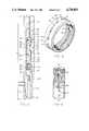
- FIG. 1is a longitudinal sectional view of the latching or locking assembly shown attached in position on the hanger body of the invention and in the condition of being run into an outer casing string with an inner pipe string suspended from the hanger body;
- FIG. 2is a longitudinal sectional view similar to FIG. 1 but showing latching fingers of the locking assembly of the invention received in the outer pipe casing prior to the shearing of the shear ring component of the invention;
- FIG. 3is a longitudinal sectional view similar to FIGS. 1 and 2 showing the locking assembly after the shearing of the shear ring and after the inner casing has moved downwardly with an enlarged diameter locking surface of the hanger body moving behind the latching fingers to hold the fingers in outwardly latched position;
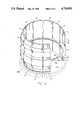
- FIG. 4is a fragmentary perspective view of the resiliently expandable and contractible locking assembly of the invention to show its orientation as it would appear in sleeved relation about the hanger body and with some of the spring-loaded latching fingers omitted and the retainer ring shown in broken lines and exploded therefrom for purposes of clarity;
- FIG. 5is a perspective view of the shear ring element of the invention, which secures the plurality of latching fingers on the hanger body;
- FIG. 6is a sectional view, partly in elevation, of the shear ring of FIG. 5.
- FIGS. 2 and 3show a tubular hanger coupling 14 which is connected as a segment in the outer casing string 16.
- the hanger coupling 14is provided with an annular inner groove near the upper end thereof which defines an inner cylindrical annular surface 18, a downward facing annular shoulder 19, and an upwardly facing lower shoulder 20 which, in essence, is a frusto-conical surface convergent inwardly towards the axis of the casing string.
- the hanger coupling 14is grooved to provide a larger inner diameter section 25 and a downward facing frusto-conical cam surface 26.
- Internal threads 27are provided in the lower end of the hanger coupling 14 which accommodates its threaded connection to the outer casing string 16.
- a similar connection(not shown) is effected at the upper end of the hanger coupling segment 14 with the upper portion of the outer casing string.
- the casing hanger 10is provided with a tubular hanger body 30 and internal threads 31 in its lower end portion for accommodating its threaded connection to an inner casing string 32 which is suspended therefrom.
- An intermediate portion of the hanger body 30is externally grooved to provide an outwardly facing recessed cylindrical surface 33, an upward facing annular abutment 34 at the lower end of the groove, and a downward facing upper annular abutment 36.
- a plurality of circumferentially spaced axially extending slots 38are formed in the exterior of the hanger body 30 at the upper end of the external groove which divide the abutment 36 and provide flow passages in the annular space between the outer casing and the hanger body 30.
- This external surface portion of the hanger body 30 which accommodates the slots 38is also grooved to provide an arcuate frusto-conical locking surface 41 with a smallest cross-sectional diameter which is larger than that of cylindrical surface 33 but which is severed by the slots 38.
- a cylindrical recessed surface 42is also formed in the hanger body exterior which joins the frusto-conical surface 41 and is also severed by the slots 38.
- a hanger support ring 43is press fit on the hanger body 30 about the surfaces 42.
- a downward facing surface 45 provided by the bottom end of the hanger support ring 43provides an upper stop shoulder for purposes hereinafter described. Adjacent its lower end, the hanger body 30 is provided with external threads 44.
- a locking assembly 46which is adapted to releasably support the hanger body 30 within the outer casing string in the hanger coupling segment 14 includes a plurality of latching fingers 47 which are arranged to fit around the hanger body 30 in sleeved relation thereto.
- the latching fingers 47are retained by a split retainer ring 48, the halves of which seat on the upward facing shoulder 34 in the hanger body 30.
- the retainer ring 48is counterbored at its upper end portion to provide an intermediate diameter bore section 49 which is grooved in its lower end portion to provide an inner annular groove 50.
- the bore section 49is a tapered frusto-conical section which is convergent downwardly.
- the lower end portions of the latching fingers 47are formed with sections 47a, 47b conforming substantially to the inner diameters of the lower end of the bore section 49 and the groove 50 of the halves of retainer ring 48 whereby a boss 51 at the lower end of each latching finger is received in the groove 50 of the retainer ring.
- the split retainer ring 48is formed with external threads conforming in size and dimension to the external threads 44 on the lower end portion of the hanger body 30.
- a connecting shear ring 55which is used to secure the retainer ring 48 in place on the hanger body 30 is provided with internal threads 56 and an inner annular groove 57 intermediate its ends which extends about its entire inner circumference to form a weakened reduced thickness portion.
- Formed in the portionare four segmental arcuate cuts or notches 62, each extending about eighty degrees (80°) of arc in the surface of the ring 55.
- Each cut 62is terminated at each end by an enlarged opening 64.
- the numbers, sizes, and dimensions of the cutsmight be other than shown to accommodate shearing at different pipe loadings.
- each of the latching fingers 47is a downward facing segment of a frusto-conical surface which is convergent inwardly whereby each finger secured against the recessed cylindrical surface 33 of the hanger body 30 with its lower boss 51 received in the retainer ring 48 is permitted a limited pivotal movement about its lower end.
- Each of the latching fingers 47is formed with an inner arcuate cylindrical surface 52 conforming in radius of curvature with that of the recessed cylindrical surface 33 of the hanger body 30. Intermediate its ends, the inner surface 52 is grooved to provide a recess 53. As assembled, the latching fingers 47 are disposed in a circular arrangement as shown in FIG. 4.
- the latching fingers 47are yieldably urged toward an expanded position by a biasing means such as a split circular spring 58 which is received in each of the grooved recesses 53.
- a biasing meanssuch as a split circular spring 58 which is received in each of the grooved recesses 53.
- the spring 58In its natural unforced state, the spring 58 is of larger diameter than that of the surface 33 of the hanger body and a gap exists between its split ends. To preclude the possibility of the ends of the spring 58 catching on the inner surfaces of the fingers 47, external bevelled surfaces 58a, 58b are formed on the end portions of the spring 58.
- the fingers 47 of the locking assembly 46are arranged in circular sleeved fashion about the recessed surface 33 of the hanger body.
- the lower end of each latching finger 47is held secured against the hanger body with the boss 51 at its lower end retained in the inner groove 50 of the split retainer ring 48.
- the retainer ring itself, both halves thereof,are held fixed on the hanger body by the shear ring 55 which threadedly connects the locking assembly 46 and the hanger body 30, as shown in FIGS. 1 and 2.
- Each of the latching fingers 47is provided on its exterior with an upper hook like portion defined by a notched portion adjacent its upper end which defines a downwardly facing stop shoulder 71 also facing toward the inner axis of the hanger body 30 with a taper conforming to that of the shoulder 20 in the hanger coupling 14.
- An upper outward facing arcuate cam surface 72is also formed on the upper end portion of each latching finger 47 extending to the end thereof. Below the stop 71 the latching finger is grooved externally to provide a recessed arcuate surface 73 immediately below the stop 71 and an upwardly and outwardly facing cam surface 75.
- Each latching finger 47also includes a boss 76 which at its upper end provides the upper cam surface 75 and at its lower end, is provided with a downward and outward facing cam surface 77.
- the cam surface 77terminates at the reduced diameter section 47a in the lower end of the latching finger.
- the boss 76defines an intermediate arcuate surface 78.
- the hanger body 30 with locking assembly 46 installed thereonis secured to a suitable running tool (not shown) and run into the bore of the outer casing string 16.
- a suitable running toolnot shown
- the arcuate surface 78 of the boss 76 of each latching finger 47is adapted to ride along the inner wall surface of the outer casing string 16 as the fingers 47 are continuously urged outwardly by the split circular spring 58.
- the upper ends of the latching fingers 47are lowered to a position where they are disposed adjacent the recessed surface 18 in the hanger coupling segment 14 in the outer casing string, the upper ends of the fingers 47 are moved outwardly by the spring 58 by pivotal movement on their lower ends whereby stop shoulders 71 on the fingers 47 engage the upward facing annular shoulder 20 in the hanger coupling 14 as shown in FIG. 2.
- the weight of the casing string 32results in the shearing of the connecting shear ring 55 along the sections 66 thereof whereby the upper section 55A of the shear ring 55 is severed from its lower section 55B as shown in FIG. 3.
- a suitable toolmay be again connected to the hanger body 30 whereby an upward lifting action on the hanger 30 will result in the latching fingers 47 being cammed inwardly by the interaction of the cam surfaces 72 and 75 of the latching fingers with the cam surfaces 19 and 26, respectively, of the hanger coupling 14 whereby the hanger assembly is in its contracted, compressed condition and upward movement of the inner casing string 32 through the outer casing string is permitted.
Landscapes
- Life Sciences & Earth Sciences (AREA)
- Engineering & Computer Science (AREA)
- Geology (AREA)
- Mining & Mineral Resources (AREA)
- Physics & Mathematics (AREA)
- Environmental & Geological Engineering (AREA)
- Fluid Mechanics (AREA)
- General Life Sciences & Earth Sciences (AREA)
- Geochemistry & Mineralogy (AREA)
- Holders For Apparel And Elements Relating To Apparel (AREA)
- Mirrors, Picture Frames, Photograph Stands, And Related Fastening Devices (AREA)
Abstract
Description
Claims (6)
Priority Applications (1)
| Application Number | Priority Date | Filing Date | Title |
|---|---|---|---|
| US06/882,873US4730851A (en) | 1986-07-07 | 1986-07-07 | Downhole expandable casting hanger |
Applications Claiming Priority (1)
| Application Number | Priority Date | Filing Date | Title |
|---|---|---|---|
| US06/882,873US4730851A (en) | 1986-07-07 | 1986-07-07 | Downhole expandable casting hanger |
Publications (1)
| Publication Number | Publication Date |
|---|---|
| US4730851Atrue US4730851A (en) | 1988-03-15 |
Family
ID=25381516
Family Applications (1)
| Application Number | Title | Priority Date | Filing Date |
|---|---|---|---|
| US06/882,873Expired - LifetimeUS4730851A (en) | 1986-07-07 | 1986-07-07 | Downhole expandable casting hanger |
Country Status (1)
| Country | Link |
|---|---|
| US (1) | US4730851A (en) |
Cited By (72)
| Publication number | Priority date | Publication date | Assignee | Title |
|---|---|---|---|---|
| US5127478A (en)* | 1989-10-18 | 1992-07-07 | National-Oilwell | Casing suspension system |
| US5507349A (en)* | 1994-12-19 | 1996-04-16 | Halliburton Company | Downhole coiled tubing latch |
| US5620052A (en)* | 1995-06-07 | 1997-04-15 | Turner; Edwin C. | Hanger suspension system |
| US20020040787A1 (en)* | 1998-12-07 | 2002-04-11 | Cook Robert Lance | Forming a wellbore casing while simultaneously drilling a wellbore |
| US20020100595A1 (en)* | 1999-02-26 | 2002-08-01 | Shell Oil Co. | Flow control system for an apparatus for radially expanding tubular members |
| US6446724B2 (en) | 1999-05-20 | 2002-09-10 | Baker Hughes Incorporated | Hanging liners by pipe expansion |
| US6470966B2 (en) | 1998-12-07 | 2002-10-29 | Robert Lance Cook | Apparatus for forming wellbore casing |
| US6484382B1 (en)* | 2000-03-23 | 2002-11-26 | Erc Industries, Inc. | Method of providing an internal circumferential shoulder in a cylindrical passageway |
| US20030024708A1 (en)* | 1998-12-07 | 2003-02-06 | Shell Oil Co. | Structral support |
| US6524032B2 (en)* | 2000-10-10 | 2003-02-25 | Cso Aker Maritime, Inc. | High capacity nonconcentric structural connectors and method of use |
| US6551030B1 (en)* | 1997-12-05 | 2003-04-22 | Britannia Engineering Consultancy Ltd. | Tubular pile connection system |
| US6557640B1 (en) | 1998-12-07 | 2003-05-06 | Shell Oil Company | Lubrication and self-cleaning system for expansion mandrel |
| US6575240B1 (en) | 1998-12-07 | 2003-06-10 | Shell Oil Company | System and method for driving pipe |
| US6575250B1 (en) | 1999-11-15 | 2003-06-10 | Shell Oil Company | Expanding a tubular element in a wellbore |
| US6634431B2 (en) | 1998-11-16 | 2003-10-21 | Robert Lance Cook | Isolation of subterranean zones |
| US6640903B1 (en) | 1998-12-07 | 2003-11-04 | Shell Oil Company | Forming a wellbore casing while simultaneously drilling a wellbore |
| US20030222455A1 (en)* | 1999-04-26 | 2003-12-04 | Shell Oil Co. | Expandable connector |
| US6712154B2 (en) | 1998-11-16 | 2004-03-30 | Enventure Global Technology | Isolation of subterranean zones |
| US6745845B2 (en) | 1998-11-16 | 2004-06-08 | Shell Oil Company | Isolation of subterranean zones |
| US20040231855A1 (en)* | 2001-07-06 | 2004-11-25 | Cook Robert Lance | Liner hanger |
| US6823937B1 (en) | 1998-12-07 | 2004-11-30 | Shell Oil Company | Wellhead |
| GB2403745A (en)* | 2003-06-13 | 2005-01-12 | Weatherford Lamb | Method of supporting a tubular in a bore |
| US6892819B2 (en) | 1998-12-07 | 2005-05-17 | Shell Oil Company | Forming a wellbore casing while simultaneously drilling a wellbore |
| US6976541B2 (en) | 2000-09-18 | 2005-12-20 | Shell Oil Company | Liner hanger with sliding sleeve valve |
| US20060102360A1 (en)* | 1998-12-07 | 2006-05-18 | Brisco David P | System for radially expanding a tubular member |
| US7048067B1 (en) | 1999-11-01 | 2006-05-23 | Shell Oil Company | Wellbore casing repair |
| US7055608B2 (en) | 1999-03-11 | 2006-06-06 | Shell Oil Company | Forming a wellbore casing while simultaneously drilling a wellbore |
| US7100684B2 (en) | 2000-07-28 | 2006-09-05 | Enventure Global Technology | Liner hanger with standoffs |
| US7100685B2 (en) | 2000-10-02 | 2006-09-05 | Enventure Global Technology | Mono-diameter wellbore casing |
| US7121352B2 (en) | 1998-11-16 | 2006-10-17 | Enventure Global Technology | Isolation of subterranean zones |
| US7168499B2 (en) | 1998-11-16 | 2007-01-30 | Shell Oil Company | Radial expansion of tubular members |
| US7168496B2 (en) | 2001-07-06 | 2007-01-30 | Eventure Global Technology | Liner hanger |
| US7172024B2 (en) | 2000-10-02 | 2007-02-06 | Shell Oil Company | Mono-diameter wellbore casing |
| US7195064B2 (en) | 1998-12-07 | 2007-03-27 | Enventure Global Technology | Mono-diameter wellbore casing |
| US7231985B2 (en) | 1998-11-16 | 2007-06-19 | Shell Oil Company | Radial expansion of tubular members |
| US7234531B2 (en) | 1999-12-03 | 2007-06-26 | Enventure Global Technology, Llc | Mono-diameter wellbore casing |
| US7258168B2 (en) | 2001-07-27 | 2007-08-21 | Enventure Global Technology L.L.C. | Liner hanger with slip joint sealing members and method of use |
| US7290605B2 (en) | 2001-12-27 | 2007-11-06 | Enventure Global Technology | Seal receptacle using expandable liner hanger |
| US7308755B2 (en) | 2003-06-13 | 2007-12-18 | Shell Oil Company | Apparatus for forming a mono-diameter wellbore casing |
| US7325602B2 (en) | 2000-10-02 | 2008-02-05 | Shell Oil Company | Method and apparatus for forming a mono-diameter wellbore casing |
| US7350564B2 (en) | 1998-12-07 | 2008-04-01 | Enventure Global Technology, L.L.C. | Mono-diameter wellbore casing |
| US7350563B2 (en) | 1999-07-09 | 2008-04-01 | Enventure Global Technology, L.L.C. | System for lining a wellbore casing |
| US7360591B2 (en) | 2002-05-29 | 2008-04-22 | Enventure Global Technology, Llc | System for radially expanding a tubular member |
| US7377326B2 (en) | 2002-08-23 | 2008-05-27 | Enventure Global Technology, L.L.C. | Magnetic impulse applied sleeve method of forming a wellbore casing |
| US7383889B2 (en) | 2001-11-12 | 2008-06-10 | Enventure Global Technology, Llc | Mono diameter wellbore casing |
| US7398832B2 (en) | 2002-06-10 | 2008-07-15 | Enventure Global Technology, Llc | Mono-diameter wellbore casing |
| US7404444B2 (en) | 2002-09-20 | 2008-07-29 | Enventure Global Technology | Protective sleeve for expandable tubulars |
| US7410000B2 (en) | 2001-01-17 | 2008-08-12 | Enventure Global Technology, Llc. | Mono-diameter wellbore casing |
| US7416027B2 (en) | 2001-09-07 | 2008-08-26 | Enventure Global Technology, Llc | Adjustable expansion cone assembly |
| US7424918B2 (en) | 2002-08-23 | 2008-09-16 | Enventure Global Technology, L.L.C. | Interposed joint sealing layer method of forming a wellbore casing |
| US7438133B2 (en) | 2003-02-26 | 2008-10-21 | Enventure Global Technology, Llc | Apparatus and method for radially expanding and plastically deforming a tubular member |
| US7503393B2 (en) | 2003-01-27 | 2009-03-17 | Enventure Global Technology, Inc. | Lubrication system for radially expanding tubular members |
| US7513313B2 (en) | 2002-09-20 | 2009-04-07 | Enventure Global Technology, Llc | Bottom plug for forming a mono diameter wellbore casing |
| US7516790B2 (en) | 1999-12-03 | 2009-04-14 | Enventure Global Technology, Llc | Mono-diameter wellbore casing |
| US7552776B2 (en) | 1998-12-07 | 2009-06-30 | Enventure Global Technology, Llc | Anchor hangers |
| US7571774B2 (en) | 2002-09-20 | 2009-08-11 | Eventure Global Technology | Self-lubricating expansion mandrel for expandable tubular |
| US7603758B2 (en) | 1998-12-07 | 2009-10-20 | Shell Oil Company | Method of coupling a tubular member |
| US7712522B2 (en) | 2003-09-05 | 2010-05-11 | Enventure Global Technology, Llc | Expansion cone and system |
| US20100116486A1 (en)* | 2008-11-12 | 2010-05-13 | Marc Minassian | Well assembly having a casing hanger supported by a load member actuated by a retractable member disposed in the wellhead |
| US7740076B2 (en) | 2002-04-12 | 2010-06-22 | Enventure Global Technology, L.L.C. | Protective sleeve for threaded connections for expandable liner hanger |
| US7739917B2 (en) | 2002-09-20 | 2010-06-22 | Enventure Global Technology, Llc | Pipe formability evaluation for expandable tubulars |
| US7775290B2 (en) | 2003-04-17 | 2010-08-17 | Enventure Global Technology, Llc | Apparatus for radially expanding and plastically deforming a tubular member |
| US7793721B2 (en) | 2003-03-11 | 2010-09-14 | Eventure Global Technology, Llc | Apparatus for radially expanding and plastically deforming a tubular member |
| US7819185B2 (en) | 2004-08-13 | 2010-10-26 | Enventure Global Technology, Llc | Expandable tubular |
| US7886831B2 (en) | 2003-01-22 | 2011-02-15 | Enventure Global Technology, L.L.C. | Apparatus for radially expanding and plastically deforming a tubular member |
| US7918284B2 (en) | 2002-04-15 | 2011-04-05 | Enventure Global Technology, L.L.C. | Protective sleeve for threaded connections for expandable liner hanger |
| US20140166315A1 (en)* | 2012-12-17 | 2014-06-19 | Baker Hughes Incorporated | Lock assembly with cageless dogs |
| US20140216721A1 (en)* | 2013-02-05 | 2014-08-07 | M-I L.L.C. | Rotating flow head apparatus |
| WO2016022450A3 (en)* | 2014-08-06 | 2016-03-31 | Weatherford Technology Holdings, Llc | Latch ring for casing hanger in casing head |
| US10731433B2 (en) | 2018-04-23 | 2020-08-04 | Ge Oil & Gas Pressure Control Lp | System and method for expandable landing locking shoulder |
| US20210131522A1 (en)* | 2019-11-04 | 2021-05-06 | Beijingwest Industries Co., Ltd. | Bracket for attachment with a hydraulic damper assembly and a method of joining a bracket and a hydraulic damper assembly |
| US11199065B2 (en)* | 2017-03-25 | 2021-12-14 | Ronald van Petegem | Latch mechanism and system for downhole applications |
Citations (8)
| Publication number | Priority date | Publication date | Assignee | Title |
|---|---|---|---|---|
| US2003446A (en)* | 1934-11-15 | 1935-06-04 | Robert L Imler | Well tubing hanger |
| US2010284A (en)* | 1933-08-15 | 1935-08-06 | Baash Ross Tool Co | Casing head |
| US3420308A (en)* | 1967-08-16 | 1969-01-07 | Fmc Corp | Well casing hanger |
| US3741589A (en)* | 1971-11-11 | 1973-06-26 | Rockwell Mfg Co | Pipe hanger |
| US3893717A (en)* | 1974-05-15 | 1975-07-08 | Putch Samuel W | Well casing hanger assembly |
| US4051896A (en)* | 1974-12-18 | 1977-10-04 | Otis Engineering Corporation | Well bore liner hanger |
| US4139059A (en)* | 1977-12-12 | 1979-02-13 | W-K-M Wellhead Systems, Inc. | Well casing hanger assembly |
| US4468055A (en)* | 1982-05-03 | 1984-08-28 | Dril Quip, Inc. | Wellhead apparatus |
- 1986
- 1986-07-07USUS06/882,873patent/US4730851A/ennot_activeExpired - Lifetime
Patent Citations (8)
| Publication number | Priority date | Publication date | Assignee | Title |
|---|---|---|---|---|
| US2010284A (en)* | 1933-08-15 | 1935-08-06 | Baash Ross Tool Co | Casing head |
| US2003446A (en)* | 1934-11-15 | 1935-06-04 | Robert L Imler | Well tubing hanger |
| US3420308A (en)* | 1967-08-16 | 1969-01-07 | Fmc Corp | Well casing hanger |
| US3741589A (en)* | 1971-11-11 | 1973-06-26 | Rockwell Mfg Co | Pipe hanger |
| US3893717A (en)* | 1974-05-15 | 1975-07-08 | Putch Samuel W | Well casing hanger assembly |
| US4051896A (en)* | 1974-12-18 | 1977-10-04 | Otis Engineering Corporation | Well bore liner hanger |
| US4139059A (en)* | 1977-12-12 | 1979-02-13 | W-K-M Wellhead Systems, Inc. | Well casing hanger assembly |
| US4468055A (en)* | 1982-05-03 | 1984-08-28 | Dril Quip, Inc. | Wellhead apparatus |
Cited By (148)
| Publication number | Priority date | Publication date | Assignee | Title |
|---|---|---|---|---|
| US5127478A (en)* | 1989-10-18 | 1992-07-07 | National-Oilwell | Casing suspension system |
| US5507349A (en)* | 1994-12-19 | 1996-04-16 | Halliburton Company | Downhole coiled tubing latch |
| US5620052A (en)* | 1995-06-07 | 1997-04-15 | Turner; Edwin C. | Hanger suspension system |
| US6551030B1 (en)* | 1997-12-05 | 2003-04-22 | Britannia Engineering Consultancy Ltd. | Tubular pile connection system |
| US7231985B2 (en) | 1998-11-16 | 2007-06-19 | Shell Oil Company | Radial expansion of tubular members |
| US7275601B2 (en) | 1998-11-16 | 2007-10-02 | Shell Oil Company | Radial expansion of tubular members |
| US7270188B2 (en) | 1998-11-16 | 2007-09-18 | Shell Oil Company | Radial expansion of tubular members |
| US7246667B2 (en) | 1998-11-16 | 2007-07-24 | Shell Oil Company | Radial expansion of tubular members |
| US20030173090A1 (en)* | 1998-11-16 | 2003-09-18 | Shell Oil Co. | Lubrication and self-cleaning system for expansion mandrel |
| US7168499B2 (en) | 1998-11-16 | 2007-01-30 | Shell Oil Company | Radial expansion of tubular members |
| US7121352B2 (en) | 1998-11-16 | 2006-10-17 | Enventure Global Technology | Isolation of subterranean zones |
| US7299881B2 (en) | 1998-11-16 | 2007-11-27 | Shell Oil Company | Radial expansion of tubular members |
| US7108072B2 (en) | 1998-11-16 | 2006-09-19 | Shell Oil Company | Lubrication and self-cleaning system for expansion mandrel |
| US7357190B2 (en) | 1998-11-16 | 2008-04-15 | Shell Oil Company | Radial expansion of tubular members |
| US6745845B2 (en) | 1998-11-16 | 2004-06-08 | Shell Oil Company | Isolation of subterranean zones |
| US6712154B2 (en) | 1998-11-16 | 2004-03-30 | Enventure Global Technology | Isolation of subterranean zones |
| US6634431B2 (en) | 1998-11-16 | 2003-10-21 | Robert Lance Cook | Isolation of subterranean zones |
| US7044218B2 (en) | 1998-12-07 | 2006-05-16 | Shell Oil Company | Apparatus for radially expanding tubular members |
| US6497289B1 (en) | 1998-12-07 | 2002-12-24 | Robert Lance Cook | Method of creating a casing in a borehole |
| US7363984B2 (en) | 1998-12-07 | 2008-04-29 | Enventure Global Technology, Llc | System for radially expanding a tubular member |
| US6575240B1 (en) | 1998-12-07 | 2003-06-10 | Shell Oil Company | System and method for driving pipe |
| US6631760B2 (en) | 1998-12-07 | 2003-10-14 | Shell Oil Company | Tie back liner for a well system |
| US7357188B1 (en) | 1998-12-07 | 2008-04-15 | Shell Oil Company | Mono-diameter wellbore casing |
| US20020040787A1 (en)* | 1998-12-07 | 2002-04-11 | Cook Robert Lance | Forming a wellbore casing while simultaneously drilling a wellbore |
| US7350564B2 (en) | 1998-12-07 | 2008-04-01 | Enventure Global Technology, L.L.C. | Mono-diameter wellbore casing |
| US20030098154A1 (en)* | 1998-12-07 | 2003-05-29 | Shell Oil Co. | Apparatus for radially expanding tubular members |
| US6640903B1 (en) | 1998-12-07 | 2003-11-04 | Shell Oil Company | Forming a wellbore casing while simultaneously drilling a wellbore |
| US7419009B2 (en) | 1998-12-07 | 2008-09-02 | Shell Oil Company | Apparatus for radially expanding and plastically deforming a tubular member |
| US7434618B2 (en) | 1998-12-07 | 2008-10-14 | Shell Oil Company | Apparatus for expanding a tubular member |
| US6470966B2 (en) | 1998-12-07 | 2002-10-29 | Robert Lance Cook | Apparatus for forming wellbore casing |
| US7552776B2 (en) | 1998-12-07 | 2009-06-30 | Enventure Global Technology, Llc | Anchor hangers |
| US7240728B2 (en) | 1998-12-07 | 2007-07-10 | Shell Oil Company | Expandable tubulars with a radial passage and wall portions with different wall thicknesses |
| US6725919B2 (en) | 1998-12-07 | 2004-04-27 | Shell Oil Company | Forming a wellbore casing while simultaneously drilling a wellbore |
| US6739392B2 (en) | 1998-12-07 | 2004-05-25 | Shell Oil Company | Forming a wellbore casing while simultaneously drilling a wellbore |
| US6561227B2 (en) | 1998-12-07 | 2003-05-13 | Shell Oil Company | Wellbore casing |
| US6758278B2 (en) | 1998-12-07 | 2004-07-06 | Shell Oil Company | Forming a wellbore casing while simultaneously drilling a wellbore |
| US7240729B2 (en) | 1998-12-07 | 2007-07-10 | Shell Oil Company | Apparatus for expanding a tubular member |
| US6823937B1 (en) | 1998-12-07 | 2004-11-30 | Shell Oil Company | Wellhead |
| US7665532B2 (en) | 1998-12-07 | 2010-02-23 | Shell Oil Company | Pipeline |
| US7216701B2 (en) | 1998-12-07 | 2007-05-15 | Shell Oil Company | Apparatus for expanding a tubular member |
| US6892819B2 (en) | 1998-12-07 | 2005-05-17 | Shell Oil Company | Forming a wellbore casing while simultaneously drilling a wellbore |
| US7603758B2 (en) | 1998-12-07 | 2009-10-20 | Shell Oil Company | Method of coupling a tubular member |
| US7198100B2 (en) | 1998-12-07 | 2007-04-03 | Shell Oil Company | Apparatus for expanding a tubular member |
| US7195064B2 (en) | 1998-12-07 | 2007-03-27 | Enventure Global Technology | Mono-diameter wellbore casing |
| US7195061B2 (en) | 1998-12-07 | 2007-03-27 | Shell Oil Company | Apparatus for expanding a tubular member |
| US7174964B2 (en) | 1998-12-07 | 2007-02-13 | Shell Oil Company | Wellhead with radially expanded tubulars |
| US20030024708A1 (en)* | 1998-12-07 | 2003-02-06 | Shell Oil Co. | Structral support |
| US7011161B2 (en) | 1998-12-07 | 2006-03-14 | Shell Oil Company | Structural support |
| US7021390B2 (en) | 1998-12-07 | 2006-04-04 | Shell Oil Company | Tubular liner for wellbore casing |
| US7036582B2 (en) | 1998-12-07 | 2006-05-02 | Shell Oil Company | Expansion cone for radially expanding tubular members |
| US7159665B2 (en) | 1998-12-07 | 2007-01-09 | Shell Oil Company | Wellbore casing |
| US7147053B2 (en) | 1998-12-07 | 2006-12-12 | Shell Oil Company | Wellhead |
| US7121337B2 (en) | 1998-12-07 | 2006-10-17 | Shell Oil Company | Apparatus for expanding a tubular member |
| US20060102360A1 (en)* | 1998-12-07 | 2006-05-18 | Brisco David P | System for radially expanding a tubular member |
| US6557640B1 (en) | 1998-12-07 | 2003-05-06 | Shell Oil Company | Lubrication and self-cleaning system for expansion mandrel |
| US7048062B2 (en) | 1998-12-07 | 2006-05-23 | Shell Oil Company | Method of selecting tubular members |
| US7108061B2 (en) | 1998-12-07 | 2006-09-19 | Shell Oil Company | Expander for a tapered liner with a shoe |
| US7077213B2 (en) | 1998-12-07 | 2006-07-18 | Shell Oil Company | Expansion cone for radially expanding tubular members |
| US7077211B2 (en) | 1998-12-07 | 2006-07-18 | Shell Oil Company | Method of creating a casing in a borehole |
| US7159667B2 (en) | 1999-02-25 | 2007-01-09 | Shell Oil Company | Method of coupling a tubular member to a preexisting structure |
| US20050183863A1 (en)* | 1999-02-25 | 2005-08-25 | Shell Oil Co. | Method of coupling a tubular member to a preexisting structure |
| US20020100595A1 (en)* | 1999-02-26 | 2002-08-01 | Shell Oil Co. | Flow control system for an apparatus for radially expanding tubular members |
| US6631759B2 (en) | 1999-02-26 | 2003-10-14 | Shell Oil Company | Apparatus for radially expanding a tubular member |
| US6857473B2 (en) | 1999-02-26 | 2005-02-22 | Shell Oil Company | Method of coupling a tubular member to a preexisting structure |
| US7044221B2 (en) | 1999-02-26 | 2006-05-16 | Shell Oil Company | Apparatus for coupling a tubular member to a preexisting structure |
| US6631769B2 (en) | 1999-02-26 | 2003-10-14 | Shell Oil Company | Method of operating an apparatus for radially expanding a tubular member |
| US6966370B2 (en) | 1999-02-26 | 2005-11-22 | Shell Oil Company | Apparatus for actuating an annular piston |
| US6705395B2 (en) | 1999-02-26 | 2004-03-16 | Shell Oil Company | Wellbore casing |
| US6568471B1 (en) | 1999-02-26 | 2003-05-27 | Shell Oil Company | Liner hanger |
| US7040396B2 (en) | 1999-02-26 | 2006-05-09 | Shell Oil Company | Apparatus for releasably coupling two elements |
| US7063142B2 (en) | 1999-02-26 | 2006-06-20 | Shell Oil Company | Method of applying an axial force to an expansion cone |
| US7556092B2 (en) | 1999-02-26 | 2009-07-07 | Enventure Global Technology, Llc | Flow control system for an apparatus for radially expanding tubular members |
| US6684947B2 (en) | 1999-02-26 | 2004-02-03 | Shell Oil Company | Apparatus for radially expanding a tubular member |
| US7438132B2 (en) | 1999-03-11 | 2008-10-21 | Shell Oil Company | Concentric pipes expanded at the pipe ends and method of forming |
| US7055608B2 (en) | 1999-03-11 | 2006-06-06 | Shell Oil Company | Forming a wellbore casing while simultaneously drilling a wellbore |
| US20030222455A1 (en)* | 1999-04-26 | 2003-12-04 | Shell Oil Co. | Expandable connector |
| US6968618B2 (en) | 1999-04-26 | 2005-11-29 | Shell Oil Company | Expandable connector |
| US6446724B2 (en) | 1999-05-20 | 2002-09-10 | Baker Hughes Incorporated | Hanging liners by pipe expansion |
| US6915852B2 (en) | 1999-05-20 | 2005-07-12 | Baker Hughes Incorporated | Hanging liners by pipe expansion |
| US20040016545A1 (en)* | 1999-05-20 | 2004-01-29 | Baugh John L. | Hanging liners by pipe expansion |
| US6631765B2 (en) | 1999-05-20 | 2003-10-14 | Baker Hughes Incorporated | Hanging liners by pipe expansion |
| US6598677B1 (en) | 1999-05-20 | 2003-07-29 | Baker Hughes Incorporated | Hanging liners by pipe expansion |
| US6561271B2 (en) | 1999-05-20 | 2003-05-13 | Baker Hughes Incorporated | Hanging liners by pipe expansion |
| US7350563B2 (en) | 1999-07-09 | 2008-04-01 | Enventure Global Technology, L.L.C. | System for lining a wellbore casing |
| US7048067B1 (en) | 1999-11-01 | 2006-05-23 | Shell Oil Company | Wellbore casing repair |
| US6575250B1 (en) | 1999-11-15 | 2003-06-10 | Shell Oil Company | Expanding a tubular element in a wellbore |
| US7516790B2 (en) | 1999-12-03 | 2009-04-14 | Enventure Global Technology, Llc | Mono-diameter wellbore casing |
| US7234531B2 (en) | 1999-12-03 | 2007-06-26 | Enventure Global Technology, Llc | Mono-diameter wellbore casing |
| US6484382B1 (en)* | 2000-03-23 | 2002-11-26 | Erc Industries, Inc. | Method of providing an internal circumferential shoulder in a cylindrical passageway |
| US7100684B2 (en) | 2000-07-28 | 2006-09-05 | Enventure Global Technology | Liner hanger with standoffs |
| US6976541B2 (en) | 2000-09-18 | 2005-12-20 | Shell Oil Company | Liner hanger with sliding sleeve valve |
| US7172021B2 (en) | 2000-09-18 | 2007-02-06 | Shell Oil Company | Liner hanger with sliding sleeve valve |
| US7172019B2 (en) | 2000-10-02 | 2007-02-06 | Shell Oil Company | Method and apparatus for forming a mono-diameter wellbore casing |
| US7172024B2 (en) | 2000-10-02 | 2007-02-06 | Shell Oil Company | Mono-diameter wellbore casing |
| US7201223B2 (en) | 2000-10-02 | 2007-04-10 | Shell Oil Company | Method and apparatus for forming a mono-diameter wellbore casing |
| US7325602B2 (en) | 2000-10-02 | 2008-02-05 | Shell Oil Company | Method and apparatus for forming a mono-diameter wellbore casing |
| US7100685B2 (en) | 2000-10-02 | 2006-09-05 | Enventure Global Technology | Mono-diameter wellbore casing |
| US7146702B2 (en) | 2000-10-02 | 2006-12-12 | Shell Oil Company | Method and apparatus for forming a mono-diameter wellbore casing |
| US7363691B2 (en) | 2000-10-02 | 2008-04-29 | Shell Oil Company | Method and apparatus for forming a mono-diameter wellbore casing |
| US7204007B2 (en) | 2000-10-02 | 2007-04-17 | Shell Oil Company | Method and apparatus for forming a mono-diameter wellbore casing |
| US7363690B2 (en) | 2000-10-02 | 2008-04-29 | Shell Oil Company | Method and apparatus for forming a mono-diameter wellbore casing |
| US6524032B2 (en)* | 2000-10-10 | 2003-02-25 | Cso Aker Maritime, Inc. | High capacity nonconcentric structural connectors and method of use |
| US7410000B2 (en) | 2001-01-17 | 2008-08-12 | Enventure Global Technology, Llc. | Mono-diameter wellbore casing |
| US20040231855A1 (en)* | 2001-07-06 | 2004-11-25 | Cook Robert Lance | Liner hanger |
| US7290616B2 (en) | 2001-07-06 | 2007-11-06 | Enventure Global Technology, L.L.C. | Liner hanger |
| US7168496B2 (en) | 2001-07-06 | 2007-01-30 | Eventure Global Technology | Liner hanger |
| US7258168B2 (en) | 2001-07-27 | 2007-08-21 | Enventure Global Technology L.L.C. | Liner hanger with slip joint sealing members and method of use |
| US7416027B2 (en) | 2001-09-07 | 2008-08-26 | Enventure Global Technology, Llc | Adjustable expansion cone assembly |
| US7383889B2 (en) | 2001-11-12 | 2008-06-10 | Enventure Global Technology, Llc | Mono diameter wellbore casing |
| US7559365B2 (en) | 2001-11-12 | 2009-07-14 | Enventure Global Technology, Llc | Collapsible expansion cone |
| US7290605B2 (en) | 2001-12-27 | 2007-11-06 | Enventure Global Technology | Seal receptacle using expandable liner hanger |
| US7740076B2 (en) | 2002-04-12 | 2010-06-22 | Enventure Global Technology, L.L.C. | Protective sleeve for threaded connections for expandable liner hanger |
| US7918284B2 (en) | 2002-04-15 | 2011-04-05 | Enventure Global Technology, L.L.C. | Protective sleeve for threaded connections for expandable liner hanger |
| US7360591B2 (en) | 2002-05-29 | 2008-04-22 | Enventure Global Technology, Llc | System for radially expanding a tubular member |
| US7398832B2 (en) | 2002-06-10 | 2008-07-15 | Enventure Global Technology, Llc | Mono-diameter wellbore casing |
| US7424918B2 (en) | 2002-08-23 | 2008-09-16 | Enventure Global Technology, L.L.C. | Interposed joint sealing layer method of forming a wellbore casing |
| US7377326B2 (en) | 2002-08-23 | 2008-05-27 | Enventure Global Technology, L.L.C. | Magnetic impulse applied sleeve method of forming a wellbore casing |
| US7404444B2 (en) | 2002-09-20 | 2008-07-29 | Enventure Global Technology | Protective sleeve for expandable tubulars |
| US7513313B2 (en) | 2002-09-20 | 2009-04-07 | Enventure Global Technology, Llc | Bottom plug for forming a mono diameter wellbore casing |
| US7571774B2 (en) | 2002-09-20 | 2009-08-11 | Eventure Global Technology | Self-lubricating expansion mandrel for expandable tubular |
| US7739917B2 (en) | 2002-09-20 | 2010-06-22 | Enventure Global Technology, Llc | Pipe formability evaluation for expandable tubulars |
| US7886831B2 (en) | 2003-01-22 | 2011-02-15 | Enventure Global Technology, L.L.C. | Apparatus for radially expanding and plastically deforming a tubular member |
| US7503393B2 (en) | 2003-01-27 | 2009-03-17 | Enventure Global Technology, Inc. | Lubrication system for radially expanding tubular members |
| US7438133B2 (en) | 2003-02-26 | 2008-10-21 | Enventure Global Technology, Llc | Apparatus and method for radially expanding and plastically deforming a tubular member |
| US7793721B2 (en) | 2003-03-11 | 2010-09-14 | Eventure Global Technology, Llc | Apparatus for radially expanding and plastically deforming a tubular member |
| US7775290B2 (en) | 2003-04-17 | 2010-08-17 | Enventure Global Technology, Llc | Apparatus for radially expanding and plastically deforming a tubular member |
| US7308755B2 (en) | 2003-06-13 | 2007-12-18 | Shell Oil Company | Apparatus for forming a mono-diameter wellbore casing |
| GB2403745A (en)* | 2003-06-13 | 2005-01-12 | Weatherford Lamb | Method of supporting a tubular in a bore |
| US20050121202A1 (en)* | 2003-06-13 | 2005-06-09 | Abercrombie Simpson Neil A. | Method and apparatus for supporting a tubular in a bore |
| GB2403745B (en)* | 2003-06-13 | 2007-12-05 | Weatherford Lamb | Method and apparatus for supporting a tubular in a bore |
| US7350588B2 (en) | 2003-06-13 | 2008-04-01 | Weatherford/Lamb, Inc. | Method and apparatus for supporting a tubular in a bore |
| US7712522B2 (en) | 2003-09-05 | 2010-05-11 | Enventure Global Technology, Llc | Expansion cone and system |
| US7819185B2 (en) | 2004-08-13 | 2010-10-26 | Enventure Global Technology, Llc | Expandable tubular |
| US20100116486A1 (en)* | 2008-11-12 | 2010-05-13 | Marc Minassian | Well assembly having a casing hanger supported by a load member actuated by a retractable member disposed in the wellhead |
| US8066064B2 (en)* | 2008-11-12 | 2011-11-29 | Vetco Gray Inc. | Well assembly having a casing hanger supported by a load member actuated by a retractable member disposed in the wellhead |
| US20140166315A1 (en)* | 2012-12-17 | 2014-06-19 | Baker Hughes Incorporated | Lock assembly with cageless dogs |
| US9212528B2 (en)* | 2012-12-17 | 2015-12-15 | Baker Hughes Incorporated | Lock assembly with cageless dogs |
| US9435165B2 (en)* | 2013-02-05 | 2016-09-06 | Smith International, Inc. | Rotating flow head apparatus |
| US20140216721A1 (en)* | 2013-02-05 | 2014-08-07 | M-I L.L.C. | Rotating flow head apparatus |
| CN106715824A (en)* | 2014-08-06 | 2017-05-24 | 韦特福特科技控股有限责任公司 | Latch ring in casing head for casing hanger |
| WO2016022450A3 (en)* | 2014-08-06 | 2016-03-31 | Weatherford Technology Holdings, Llc | Latch ring for casing hanger in casing head |
| US10018008B2 (en) | 2014-08-06 | 2018-07-10 | Weatherford Technology Holdings, Llc | Composite fracture plug and associated methods |
| AU2015301320B2 (en)* | 2014-08-06 | 2018-08-30 | Weatherford Technology Holdings, Llc | Latch ring for casing hanger in casing head |
| CN106715824B (en)* | 2014-08-06 | 2019-07-26 | 韦特福特科技控股有限责任公司 | Latch ring in casing head for casing hanger |
| US11199065B2 (en)* | 2017-03-25 | 2021-12-14 | Ronald van Petegem | Latch mechanism and system for downhole applications |
| US10731433B2 (en) | 2018-04-23 | 2020-08-04 | Ge Oil & Gas Pressure Control Lp | System and method for expandable landing locking shoulder |
| US20210131522A1 (en)* | 2019-11-04 | 2021-05-06 | Beijingwest Industries Co., Ltd. | Bracket for attachment with a hydraulic damper assembly and a method of joining a bracket and a hydraulic damper assembly |
| US11512758B2 (en)* | 2019-11-04 | 2022-11-29 | Beijingwest Industries Co., Ltd. | Bracket for attachment with a hydraulic damper assembly and a method of joining a bracket and a hydraulic damper assembly |
Similar Documents
| Publication | Publication Date | Title |
|---|---|---|
| US4730851A (en) | Downhole expandable casting hanger | |
| US4139059A (en) | Well casing hanger assembly | |
| US7040407B2 (en) | Collet load shoulder | |
| US4773477A (en) | Well suspension assembly | |
| US3015362A (en) | Well apparatus | |
| US6012519A (en) | Full bore tubing hanger system | |
| US6112818A (en) | Downhole setting tool for an expandable tubing | |
| US5069288A (en) | Single trip casing hanger/packoff running tool | |
| US10260303B2 (en) | Iris fishing tool overshot catch | |
| US5758723A (en) | Fluid pressure deactivated thru-tubing centralizer | |
| US4911244A (en) | Marine casing suspension apparatus | |
| US5249629A (en) | Full bore casing hanger running tool | |
| US2410589A (en) | Automatic slip mechanism | |
| US3171674A (en) | Well head apparatus | |
| US3741589A (en) | Pipe hanger | |
| US3472530A (en) | Pipe apparatus | |
| AU2016227750B2 (en) | Device for setting and retrieving a crown plug in and from a well head | |
| US10066456B2 (en) | Well assembly with self-adjusting lockdown assembly | |
| US4577686A (en) | Mudline support hanger assembly | |
| US3934648A (en) | Well tubing system with orienting coupling means | |
| US5984008A (en) | Installable load shoulder for use in a wellhead to support a tubing hanger | |
| US5020593A (en) | Latch ring for connecting tubular members | |
| US3424477A (en) | Well apparatus | |
| US6138751A (en) | Hanger assembly | |
| US3367002A (en) | Automatic slip setting drill pipe suspension apparatus |
Legal Events
| Date | Code | Title | Description |
|---|---|---|---|
| AS | Assignment | Owner name:JOY MANUFACTURING COMPANY, 301 GRANT STREET, PHILA Free format text:ASSIGNMENT OF ASSIGNORS INTEREST.;ASSIGNOR:WATTS, GERALD D.;REEL/FRAME:004588/0846 Effective date:19860625 | |
| AS | Assignment | Owner name:COOPER INDUSTRIES, INC. Free format text:ASSIGNMENT OF ASSIGNORS INTEREST.;ASSIGNOR:JOY MANUFACTURING COMPANY;REEL/FRAME:004688/0506 Effective date:19870204 Owner name:COOPER INDUSTRIES, INC.,TEXAS Free format text:ASSIGNMENT OF ASSIGNORS INTEREST;ASSIGNOR:JOY MANUFACTURING COMPANY;REEL/FRAME:004688/0506 Effective date:19870204 Owner name:COOPER INDUSTRIES, INC., TEXAS Free format text:ASSIGNMENT OF ASSIGNORS INTEREST;ASSIGNOR:JOY MANUFACTURING COMPANY;REEL/FRAME:004688/0506 Effective date:19870204 | |
| STCF | Information on status: patent grant | Free format text:PATENTED CASE | |
| FPAY | Fee payment | Year of fee payment:4 | |
| AS | Assignment | Owner name:COOPER CAMERON CORPORATION, TEXAS Free format text:ASSIGNMENT OF ASSIGNORS INTEREST;ASSIGNOR:COOPER INDUSTRIES, INC.;REEL/FRAME:007462/0622 Effective date:19950417 | |
| FPAY | Fee payment | Year of fee payment:8 | |
| FEPP | Fee payment procedure | Free format text:PAYOR NUMBER ASSIGNED (ORIGINAL EVENT CODE: ASPN); ENTITY STATUS OF PATENT OWNER: LARGE ENTITY | |
| FPAY | Fee payment | Year of fee payment:12 |