US4728974A - Apparatus for supporting an imaging device - Google Patents
Apparatus for supporting an imaging deviceDownload PDFInfo
- Publication number
- US4728974A US4728974AUS06/868,752US86875286AUS4728974AUS 4728974 AUS4728974 AUS 4728974AUS 86875286 AUS86875286 AUS 86875286AUS 4728974 AUS4728974 AUS 4728974A
- Authority
- US
- United States
- Prior art keywords
- supporting device
- axis
- camera
- camera supporting
- fiber scope
- Prior art date
- Legal status (The legal status is an assumption and is not a legal conclusion. Google has not performed a legal analysis and makes no representation as to the accuracy of the status listed.)
- Expired - Lifetime
Links
Images


Classifications
- B—PERFORMING OPERATIONS; TRANSPORTING
- B25—HAND TOOLS; PORTABLE POWER-DRIVEN TOOLS; MANIPULATORS
- B25J—MANIPULATORS; CHAMBERS PROVIDED WITH MANIPULATION DEVICES
- B25J19/00—Accessories fitted to manipulators, e.g. for monitoring, for viewing; Safety devices combined with or specially adapted for use in connection with manipulators
- B25J19/02—Sensing devices
- B25J19/021—Optical sensing devices
- B25J19/025—Optical sensing devices including optical fibres
- B—PERFORMING OPERATIONS; TRANSPORTING
- B23—MACHINE TOOLS; METAL-WORKING NOT OTHERWISE PROVIDED FOR
- B23K—SOLDERING OR UNSOLDERING; WELDING; CLADDING OR PLATING BY SOLDERING OR WELDING; CUTTING BY APPLYING HEAT LOCALLY, e.g. FLAME CUTTING; WORKING BY LASER BEAM
- B23K9/00—Arc welding or cutting
- B23K9/095—Monitoring or automatic control of welding parameters
- B23K9/0956—Monitoring or automatic control of welding parameters using sensing means, e.g. optical
- B—PERFORMING OPERATIONS; TRANSPORTING
- B25—HAND TOOLS; PORTABLE POWER-DRIVEN TOOLS; MANIPULATORS
- B25J—MANIPULATORS; CHAMBERS PROVIDED WITH MANIPULATION DEVICES
- B25J19/00—Accessories fitted to manipulators, e.g. for monitoring, for viewing; Safety devices combined with or specially adapted for use in connection with manipulators
- B25J19/0025—Means for supplying energy to the end effector
Definitions
- the present inventionrelates to an apparatus for supporting and, more particularly, to an apparatus of the type to attach and support a camera-supporting device equipped with a camera therein and a fiber scope to the wrist of a robot having a swing axis and a twist axis.
- the apparatus for supportingcomprises: a tube having high rigidity into which a fiber scope is inserted and which couples a camera supporting device with a robot wrist; a first identical moving member for allowing the camera-supporting device to perform the same motion as the swing axis in the direction of the swing axis around the rotational center of the swing axis as the rotational center; and a second identical moving member for allowing the camera supporting device to perform the same motion as the twist axis, so that the rotational center of the camera supporting device is located on the rotational center of the twist axis.
- Another apparatus for supportingcomprises: a rotational angle control motor which is attached to a robot wrist so that its output shaft coincides with the rotational axis of the twist axis and controls the angle of rotation of a fiber scope; a fiber scope supporting device attached to the output shaft of a reducer coupled with the output shaft of a rotational angle control motor; a tube having high rigidity into which the fiber scope is inserted and which couples a camera supporting device with the fiber scope-supporting device; a first identical moving member for allowing the camera supporting device to perform the same motion as the swing axis in the direction of the swing axis around the rotational center of the swing axis as the rotational center; and a second identical moving member for allowing the camera supporting device to perform the same motion as the twist axis so that the rotational center of the camera supporting device is located on the rotational center of the twist axis.
- the highly rigid tubeis clamped as a rigid member by the robot wrist (or fiber scope supporting device) and camera supporting device, even in the case of the driving of any of the swing and twist axes as well, the camera supporting device, tube, and fiber scope supporting device move integrally with the robot wrist.
- the camera supporting device, tube, and fiber scopeintergrally rotate around the robot wrist. Consequently, no external force is applied to the fiber scope inserted into the tube due to the rotation of the swing and twist axes and of the fiber scope, so that the angle of bend of the fiber scope is held to the angle of bend of the tube and no twist occurs.
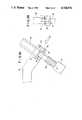
- FIG. 1Ais a partially cut-away front view of the main part of a welding robot according to an embodiment of the present invention
- FIG. 1Bis a partially cut-away perspective view of FIG. 1A when seen in the direction indicated by arrow A in FIG. 1A;
- FIG. 2is a perspective view illustrating the internal construction of the camera enclosing box 23 in FIGS. 1A and 1B;
- FIG. 3Ais a detailed diagram showing the fiber scope-attaching section 31 in FIGS. 1A and 1B;
- FIG. 3Bis a perspective view of FIG. 3A when seen in the direction indicated by arrow B in FIG. 3A;
- FIG. 4is a block diagram for a servo control at the position of the R axis.
- FIG. 1Ais a front view of the main part of a welding robot of an embodiment of the invention.
- FIG. 1Bis a perspective view of FIG. 1A when seen in the direction of arrow A.
- 1denotes an upper arm of the robot having two wrist axes; 2 is the direction of a wrist swing axis (hereinafter referred to as the B axis) which is rotated by a motor (not shown); 3 the rotational center O of the B axis; 2' the direction of a wrist twist axis (hereinafter referred to as the T axis) which is rotated by a motor (not shown); 3' the rotational center O of the T axis which passes through the rotational center 3 of the B axis and perpendicularly crosses the center 3; 4 a robot wrist to which the motions of the B axis 2 and T axis 2' are transferred; 5 a welding torch supporting rod coupled with the robot wrist 4; 6 a welding torch; 7 a wire electrode; 8 a welding
- 20indicates an attaching seat A vertically attached to the rotational center 3 of the B axis in such a manner that when the B axis 2 rotates, a camera enclosing box 23, which will be explained hereinafter, is rotated synchronously with the B axis 2 around the rotational center 3 of the B axis 2 as a rotational center.
- 21represents a bearing in which the outer race is fixed to the attaching seat A and the rotational center of the inner race coincides with the rotational center of the T axis 2' and with the rotational center 3' of the R axis such that the inner race rotates synchronously with the rotation of the T axis 2'.
- the camera enclosing box 23denotes an attaching seat B in which one end is fixed to the spigot of the inner race of the bearing 21 and the other end is fixed to the camera enclosing box 23 in a manner such that the camera enclosing box 23 is rotated synchronously with the T axos 2' and R axis motor 11 around the rotational center of the T axis and rotational center 3' of the R axis as rotational centers.
- the camera enclosing box 23is fixed onto the attaching seat B 22 so that the center of gravity is located on the rotational center of the inner race of the bearing 21, rotational center 3' of the T axis, and rotational center of the R axis motor 11.
- 24denotes the fiber scope
- 25is an image pickup section on the object side of the fiber scope 24
- 26an image pickup section on the camera side of the fiber scope 24
- 27an object lens
- 28a focus adjustment screw
- 29an attaching metal fitting of the fiber scope 24
- 30a tube having high rigidity (e.g., steel tube) for coupling as a rigid member the fiber scope supporting device 16 with the camera enclosing box 23
- 31a fiber scope attaching section, which will be explained hereinafter in FIG. 3
- 32a cable to transmit a video signal (i.e., image pickup signal) to an image processor (not shown).
- FIG. 2is a perspective view illustrating the inner construction of the camera enclosing box 23.
- 33denotes a camera image pickup section (e g., CCD image sensing chip section); 34 a camera lens; 35 a screw to attach the fiber scope 24; 36 a plurality of optical filters; 37 a rotary solenoid; 38 an on/off driving electric wire of the rotary solenoid; 39 a pole brace which operates in association with the motion of the rotary axis of the rotary solenoid 37; 40 the moving direction of the pole brace 39; 41 an attaching part to fix the optical filters 36 to the pole brace 39; X-X' an optical axis of the camera; 100 a cylindrical shutter to shut off the the optical axis having a small thickness formed of a material having a samll specific gravity (e.g., carbon fibers); 101 a shutter motor; 102 an output shaft of the shutter motor 101; and 42 a camera adapter which is formed by splitting and working part of a cylindrical body
- a control signal to turn on and off the camera video signal in accordance with the welding stateis given to the shutter motor 101 from a shutter motor controller (not shown).
- the output shaft 102 of the shutter motor 101is rotated by only a predetermined angle, thereby allowing the shutter 100 to turn on and off the camera video signal.
- FIG. 3Ais a detailed diagram of the fiber scope attaching section 31 in FIGS. 1A and 1B.
- FIG. 3Bis a perspective view of FIG. 3A when seen in the direction of arrow B in FIG. 3A.
- 43denotes a split portion to individually attach the tube 30 and attaching metal fitting 29 having different outer diameters to the fiber scope supporting device 16.
- 44is a screw to attach the tube 30; 45 a two-split collar to fix the fiber scope attaching metal fitting 29 having an outer diameter smaller than the tube 30; and 46 a screw to attach the collars 45.
- FIG. 4is a block diagram of a servo control of the R axis position.
- 50denotes an R axis position command pulse;
- 51a feedback pulse of the encoder 12;
- 52a conventional position controller consisting of a deviation counter and a digital-to-analog (D/A) converter;
- 53a conventional frequency-to-voltage (F/V) converter to generate a rotating speed signal of the R axis motor 11;
- 54a speed feedback signal; 55 an analog speed command; and 56 conventional servo amplifier.
- D/Adigital-to-analog
- F/Vfrequency-to-voltage
- the rotary solenoid 37is excited (turned on) through the electric wire 38 and a plurality of optical filters 36 are positioned on the camera optical axis X-X'.
- the optical information of the welding arc 8 and molten pool 9 transmitted through the objective lens 27, image pickup section 25, fiber scope 24, image pickup section 26, and camera lens 34is filtered by the filters 36 so that the amount of light is reduced and an optical image is formed in the camera image pickup section 33.
- This optical informationis transmitted to the image processor (not shown) by way of the cable 32 and image processed.
- the robot constitution axesare controlled on the basis of the signal after the image is processed.
- the R axis motor 11is rotated so that the position of the welding torch 6 after the rotational angles of the B axis 2 and T axis 2' is suitably determined: in other words, the relative position between the direction of the wire electrode 7 and the welding line can be accurately observed by the object lens 27.
- the rotation control servo operation in this caseis executed on the basis of a conventional servo loop shown in FIG. 4.
- each component partoperates in the following manner:
- the attaching seats A 20 and B 22, camera enclosing box 23, robot wrist 4, tubular casing 15, and fiber scope supporting device 16move intergrally.
- the fiber scope supporting device 16, camera enclosing box 23, attaching seat B 22, and rotational center of the inner race of the bearing 21move intergrally.
Landscapes
- Engineering & Computer Science (AREA)
- Mechanical Engineering (AREA)
- Robotics (AREA)
- Physics & Mathematics (AREA)
- Plasma & Fusion (AREA)
- Manipulator (AREA)
Abstract
Description
1. Field of the Invention
The present invention relates to an apparatus for supporting and, more particularly, to an apparatus of the type to attach and support a camera-supporting device equipped with a camera therein and a fiber scope to the wrist of a robot having a swing axis and a twist axis.
2. Description of the Related Art
As means for automating the work of industrial robots, there have been put into practical use industrial robots equipped with imaging equipment in which a camera is attached to the wrist of the robot together with a working tool such as a welding torch, sizing gun, deburring tool, screw fastening tool or clamping hand.
In these robots, a problem occurs with respect to the approach to an object to be worked which has a complicated shape. Practically speaking, an interference problem occurs between the object to be worked and the optical system of the camera. The large-sized camera optical system obstructs the approach to the narrow portion of the object to be worked, so that this narrow portion becomes a dead angle or dead space and the visual function of the optical system is obstructed. To solve this problem, there has been considered an imaging apparatus in which a fiber scope is attached to the robot wrist and an image pickup signal which is obtained at the edge of the fiber scope is transmitted through the fiber scope to a camera which is arranged at a remote position, for example, at the position of the upper arm of the robot, thereby miniaturizing the camera optical system. However, in this imaging apparatus, there occurs the problem that the bundles of the optical fibers in the image pickup section on the object side of the fiber scope, which is constituted by tens of thousands of optical fibers, in the image pickup section on the camera side, and at the position between the object and camera sides are twisted and bent due to the motion of the robot wrist, with the result that the optical fiber lines are severed. If the motion of the robot wrist axis is restricted such that the degrees of twist and bend of the fiber scope lie within allowable ranges, the moving range of the robot wrist in turn becomes too small, with the result that the function as the robot cannot be efficiently utilized.
It is an object of the present invention to provide an apparatus for supporting in which the fiber scope is not twisted within the operating range of the robot wrist and, at the same time, the degree of bend of the fiber scope can be held to a constant value below an allowable bend value of the fiber scope at any position within the operating range of the robot wrist axis, thereby enabling interference between the object to be work and the optical system to be remarkably improved.
The apparatus for supporting according to the present invention comprises: a tube having high rigidity into which a fiber scope is inserted and which couples a camera supporting device with a robot wrist; a first identical moving member for allowing the camera-supporting device to perform the same motion as the swing axis in the direction of the swing axis around the rotational center of the swing axis as the rotational center; and a second identical moving member for allowing the camera supporting device to perform the same motion as the twist axis, so that the rotational center of the camera supporting device is located on the rotational center of the twist axis.
Another apparatus for supporting according to the invention comprises: a rotational angle control motor which is attached to a robot wrist so that its output shaft coincides with the rotational axis of the twist axis and controls the angle of rotation of a fiber scope; a fiber scope supporting device attached to the output shaft of a reducer coupled with the output shaft of a rotational angle control motor; a tube having high rigidity into which the fiber scope is inserted and which couples a camera supporting device with the fiber scope-supporting device; a first identical moving member for allowing the camera supporting device to perform the same motion as the swing axis in the direction of the swing axis around the rotational center of the swing axis as the rotational center; and a second identical moving member for allowing the camera supporting device to perform the same motion as the twist axis so that the rotational center of the camera supporting device is located on the rotational center of the twist axis.
Since the highly rigid tube is clamped as a rigid member by the robot wrist (or fiber scope supporting device) and camera supporting device, even in the case of the driving of any of the swing and twist axes as well, the camera supporting device, tube, and fiber scope supporting device move integrally with the robot wrist. By controlling the angle of rotation of the fiber scope, the camera supporting device, tube, and fiber scope intergrally rotate around the robot wrist. Consequently, no external force is applied to the fiber scope inserted into the tube due to the rotation of the swing and twist axes and of the fiber scope, so that the angle of bend of the fiber scope is held to the angle of bend of the tube and no twist occurs.
The above and other objects, features and advantages of the present invention will be more apparent from the following detailed description in conjunction with the accompanying drawings:
FIG. 1A is a partially cut-away front view of the main part of a welding robot according to an embodiment of the present invention;
FIG. 1B is a partially cut-away perspective view of FIG. 1A when seen in the direction indicated by arrow A in FIG. 1A;
FIG. 2 is a perspective view illustrating the internal construction of the camera enclosingbox 23 in FIGS. 1A and 1B;
FIG. 3A is a detailed diagram showing the fiber scope-attachingsection 31 in FIGS. 1A and 1B;
FIG. 3B is a perspective view of FIG. 3A when seen in the direction indicated by arrow B in FIG. 3A; and
FIG. 4 is a block diagram for a servo control at the position of the R axis.
An embodiment of the present invention will now be described in detail hereinbelow with reference to the drawings using an example of a welding torch as one of the working tools. However, in place of the welding torch, a sizing gun, deburring tool, screw fatening tool, clamping hand, or similar equipment can be also used in an apparatus for supporting according to the invention. Therefore, it should be noted that the present invention is not limited only to wclding applications.
FIG. 1A is a front view of the main part of a welding robot of an embodiment of the invention. FIG. 1B is a perspective view of FIG. 1A when seen in the direction of arrow A. In the diagrams, 1 denotes an upper arm of the robot having two wrist axes; 2 is the direction of a wrist swing axis (hereinafter referred to as the B axis) which is rotated by a motor (not shown); 3 the rotational center O of the B axis; 2' the direction of a wrist twist axis (hereinafter referred to as the T axis) which is rotated by a motor (not shown); 3' the rotational center O of the T axis which passes through therotational center 3 of the B axis and perpendicularly crosses thecenter 3; 4 a robot wrist to which the motions of theB axis 2 and T axis 2' are transferred; 5 a welding torch supporting rod coupled with the robot wrist 4; 6 a welding torch; 7 a wire electrode; 8 a welding arc; 9 a molten pool just under the welding arc 8; 10 a base material; 11 a rotational angle control motor to control the angle of rotation of the rotational axis (hereinafter referred to as the R axis) of afiber scope 24, which will be explained hereinafter; 12 an encoder to detect the angle of rotation of themotor 11; 13 a reduction gear; 14 an output shaft of thereduction gear 13, i.e., an output shaft of the R axis; 15 a tubular casing to fix thereduction gear 13 to the robot wrist 4 such that the rotational center of the R axis (output shaft) coincides with the rotational center of the T axis; 16 a fiber scope supporting device fixed to theoutput shaft 14 of the motor 11 (i.e., the R axis); 17 an origin detecting limit switch attached to the fiberscope supporting device 16 to position the origin of the R axis; 18 an overrun limit switch to determined the limit position on the side opposite to the origin of theR axis motor 11; and 19 a dog fixed onto thetubular casing 15 for thelimit switches rotational center 3 of the B axis in such a manner that when theB axis 2 rotates, a camera enclosingbox 23, which will be explained hereinafter, is rotated synchronously with theB axis 2 around therotational center 3 of theB axis 2 as a rotational center. 21 represents a bearing in which the outer race is fixed to the attaching seat A and the rotational center of the inner race coincides with the rotational center of the T axis 2' and with the rotational center 3' of the R axis such that the inner race rotates synchronously with the rotation of theT axis 2'. 22 denotes an attaching seat B in which one end is fixed to the spigot of the inner race of thebearing 21 and the other end is fixed to the camera enclosingbox 23 in a manner such that the camera enclosingbox 23 is rotated synchronously with the T axos 2' andR axis motor 11 around the rotational center of the T axis and rotational center 3' of the R axis as rotational centers. As will be explained in detail hereinafter with reference to FIG. 2, the camera enclosingbox 23 is fixed onto the attachingseat B 22 so that the center of gravity is located on the rotational center of the inner race of thebearing 21, rotational center 3' of the T axis, and rotational center of theR axis motor 11. Further, 24 denotes the fiber scope; 25 is an image pickup section on the object side of thefiber scope 24; 26 an image pickup section on the camera side of thefiber scope 24; 27 an object lens; 28 a focus adjustment screw; 29 an attaching metal fitting of thefiber scope 24; 30 a tube having high rigidity (e.g., steel tube) for coupling as a rigid member the fiberscope supporting device 16 with the camera enclosingbox 23; 31 a fiber scope attaching section, which will be explained hereinafter in FIG. 3; 32 a cable to transmit a video signal (i.e., image pickup signal) to an image processor (not shown).
FIG. 2 is a perspective view illustrating the inner construction of the camera enclosingbox 23. In the diagram, 33 denotes a camera image pickup section (e g., CCD image sensing chip section); 34 a camera lens; 35 a screw to attach thefiber scope 24; 36 a plurality of optical filters; 37 a rotary solenoid; 38 an on/off driving electric wire of the rotary solenoid; 39 a pole brace which operates in association with the motion of the rotary axis of therotary solenoid 37; 40 the moving direction of thepole brace 39; 41 an attaching part to fix theoptical filters 36 to thepole brace 39; X-X' an optical axis of the camera; 100 a cylindrical shutter to shut off the the optical axis having a small thickness formed of a material having a samll specific gravity (e.g., carbon fibers); 101 a shutter motor; 102 an output shaft of theshutter motor 101; and 42 a camera adapter which is formed by splitting and working part of a cylindrical body in order to make theoptical filters 36 operative and inoperative and to attach theshutter motor 101. A control signal to turn on and off the camera video signal in accordance with the welding state is given to theshutter motor 101 from a shutter motor controller (not shown). In response to this control signal, theoutput shaft 102 of theshutter motor 101 is rotated by only a predetermined angle, thereby allowing the shutter 100 to turn on and off the camera video signal.
FIG. 3A is a detailed diagram of the fiberscope attaching section 31 in FIGS. 1A and 1B. FIG. 3B is a perspective view of FIG. 3A when seen in the direction of arrow B in FIG. 3A. In the diagrams, 43 denotes a split portion to individually attach thetube 30 and attachingmetal fitting 29 having different outer diameters to the fiberscope supporting device 16. 44 is a screw to attach thetube 30; 45 a two-split collar to fix the fiber scope attachingmetal fitting 29 having an outer diameter smaller than thetube 30; and 46 a screw to attach thecollars 45.
FIG. 4 is a block diagram of a servo control of the R axis position. In the diagram, 50 denotes an R axis position command pulse; 51 a feedback pulse of theencoder 12; 52 a conventional position controller consisting of a deviation counter and a digital-to-analog (D/A) converter; 53 a conventional frequency-to-voltage (F/V) converter to generate a rotating speed signal of theR axis motor 11; 54 a speed feedback signal; 55 an analog speed command; and 56 conventional servo amplifier.
The operation of the embodiment will now be described.
When the welding arc 8 and molten pool 9 are observed, therotary solenoid 37 is excited (turned on) through theelectric wire 38 and a plurality ofoptical filters 36 are positioned on the camera optical axis X-X'. The optical information of the welding arc 8 and molten pool 9 transmitted through theobjective lens 27,image pickup section 25,fiber scope 24,image pickup section 26, andcamera lens 34 is filtered by thefilters 36 so that the amount of light is reduced and an optical image is formed in the camera image pickup section 33. This optical information is transmitted to the image processor (not shown) by way of thecable 32 and image processed. The robot constitution axes are controlled on the basis of the signal after the image is processed. However, since the image processing method and the robot control method are not directly related to the feature of the present invention, their descriptions are omitted in this specification. When the shape of the base material in the extinguished state of the welding arc 8 is observed, therotary solenoid 37 is turned off, thepole brace 39 is rotated, and all of thefilters 36 are completely deviated from the camera optical axis X-X'. The other operations are substantially the same as those in the flow of the optical information described above.
When the welding arc 8 and molten pool 9 is observed, or when the shape of the base material is observed, three fundamental axes (not shown) of the robot, T axis 2',B axis 2, andR axis motor 11 are properly rotated to obtain the desired optical information. These three fundamental axes of the robot are used to three-dimensionally move the robot wrist 4, i.e.,wire electrode 7. Since this motion is not directly related to the bend and twist of thefiber scope 24 as the feature of the invention, its description is omitted in this specification. TheB axis 2 and T axis 2' are rotated such that the torch angle and the angle of forward/backward movement for the welding line (not shown) of thewelding torch 6 are held to proper angles for welding. Separately, theR axis motor 11 is rotated so that the position of thewelding torch 6 after the rotational angles of theB axis 2 and T axis 2' is suitably determined: in other words, the relative position between the direction of thewire electrode 7 and the welding line can be accurately observed by theobject lens 27. The rotation control servo operation in this case is executed on the basis of a conventional servo loop shown in FIG. 4.
As described in FIGS. 1A and 1B, since the highlyrigid tube 30 is clamped as a rigid member by the fiberscope supporing device 16 andcamera enclosing box 23, each component part operates in the following manner:
(1) In the driving mode of the B axis:
The attaching seats A 20 andB 22,camera enclosing box 23, robot wrist 4,tubular casing 15, and fiberscope supporting device 16 move intergrally.
(2) In the driving mode of the T axis:
The robot wrist 4,tubular casing 15, fiberscope supporting device 16,camera enclosing box 23, attachingseat B 22, and the rotational center of the inner race of thebearing 21 move intergrally.
(3) In the driving mode of the R axis:
The fiberscope supporting device 16,camera enclosing box 23, attachingseat B 22, and rotational center of the inner race of thebearing 21 move intergrally.
Therefore, no external force is applied to thefiber scope 24 inserted in thetube 30 due to the driving of the T, B, and R axes. The angle of bend of thefiber scope 24 is held to the angle of bend of the tube 30 (this angle is set to a value below the allowable bending angle of the fiber scope 24), so that no twist occurs at all. In addition, as described in FIGS. 1A and 1B, since a groove 23' is formed in thecamera enclosing box 23 in order to adjust the center of total gravities of thebox 23 andtube 30, the load of theR axis motor 11 becomes only the inertial load which is reduced to the value which is a factor of the square of the reduction ratio of thereduction gear 13. Therefore, no weight load is applied and it is sufficient to use a samll-sized motor having a small capacity as theR axis motor 11.
Although the present invention has been shown and described with respect to a preferred embodiment, various changes and modifications which are obvious to a person skilled in the art to which the invention pertains are deemed to lie within the spirit and scope of the invention.
Claims (18)
1. An apparatus for supporting in which a camera supporting device having a camera therein and a fiber scope are attached to and supported the wrist of a robot having a swing axis and a twist axis, comprising:
a tube having high rigidity into which said fiber scope is inserted and which connects said camera supporting device with said robot wrist;
first identical moving means for allowing the camera supporting device to perform the same motion as said swing axis in the direction of the swing axis around the rotational center of the swing axis as the rotational center; and
second identical moving means for allowing the camera supporting device to perform the same motion as said twist axis such that the rotational center of the camera supporing device is located on the rotational center of the twist axis.
2. An apparatus according to claim 1, wherein said camera supporting device is formed with a groove adapted to adjust the center of gravity.
3. An apparatus according to claim 1 or 2, wherein a bearing is provided as said second identical moving means.
4. An apparatus according to claim 3, wherein an outer race of said bearing is coupled with an attaching seat which is vertical to the rotational center of the swing axis.
5. An apparatus according to claim 4, wherein said camera supporting device has an automatic filter switching device therein.
6. An apparatus according to claim 5, wherein said camera supporting device has a shutter switching device therein.
7. An apparatus according to claim 1, wherein said camera supporting device has an automatic filter switching device therein.
8. An apparatus according to claim 2, wherein said camera supporting device has an automatic filter switching device therein.
9. An apparatus according to claim 3, wherein said camera supporting device has an automatic filter switching device therein.
10. An apparatus for supporting in which a camera supporting device having a camera therein and a fiber scope are attached to and supported on the wrist of a robot having a swing axis and a twist axis, comprising:
a rotational angle control motor, attached to said robot wrist such that its output shaft coincides with the rotational axis of said twist axis, for controlling the angle of rotation of said fiber scope;
a fiber scope supporting device attached to an output shaft of a reduction gear coupled with the output shaft of said rotational angle control motor;
a tube having high rigidity into which said fiber scope is inserted and which connects said camera supporting device with said fiber scope supporting device;
first identical moving means for allowing the camera supporting device to perform the same motion as said swing axis in the direction of the swing axis around the rotational center of the swing axis as the rotational center; and
second identical moving means for allowing the camera supporting device to perform the same motion as said twist axis such that the rotational center of the camera supporting device is located on the rotational center of the twist axis.
11. An apparatus according to claim 10, wherein said camera supporting device is formed with a groove adapted to adjust the center of gravity.
12. An apparatus according to claim 10 or 11, wherein a bearing is provided as said second identical moving means.
13. An apparatus according to claim 12, wherein an outer race of said bearing is coupled with an attaching seat which is vertical to the rotational center of the swing axis.
14. An apparatus according to claim 13 wherein said camera supporting device has an automatic filter switching device therein.
15. An apparatus according to claim 14, wherein said camera supporting device has a shutter switching device therein.
16. An apparatus according to claim 10, wherein said camera supporting device has an automatic filter switching device therein.
17. An apparatus according to claim 11, wherein said camera supporting device has an automatic filter switching device therein.
18. An apparatus according to claim 12, wherein said camera supporting device has an automatic filter switching device therein.
Applications Claiming Priority (2)
| Application Number | Priority Date | Filing Date | Title |
|---|---|---|---|
| JP60-116560 | 1985-05-31 | ||
| JP60116560AJPS61279491A (en) | 1985-05-31 | 1985-05-31 | Industrial robot with visual equipment |
Publications (1)
| Publication Number | Publication Date |
|---|---|
| US4728974Atrue US4728974A (en) | 1988-03-01 |
Family
ID=14690132
Family Applications (1)
| Application Number | Title | Priority Date | Filing Date |
|---|---|---|---|
| US06/868,752Expired - LifetimeUS4728974A (en) | 1985-05-31 | 1986-05-30 | Apparatus for supporting an imaging device |
Country Status (4)
| Country | Link |
|---|---|
| US (1) | US4728974A (en) |
| EP (1) | EP0205288B1 (en) |
| JP (1) | JPS61279491A (en) |
| DE (1) | DE3673250D1 (en) |
Cited By (59)
| Publication number | Priority date | Publication date | Assignee | Title |
|---|---|---|---|---|
| US5153718A (en)* | 1990-11-16 | 1992-10-06 | Jack Massar | Cutting apparatus with viewer |
| US5383472A (en)* | 1993-07-22 | 1995-01-24 | Devlin; Mark T. | Method and apparatus for handling of biopsy tissue specimen |
| US5515478A (en)* | 1992-08-10 | 1996-05-07 | Computer Motion, Inc. | Automated endoscope system for optimal positioning |
| US5524180A (en)* | 1992-08-10 | 1996-06-04 | Computer Motion, Inc. | Automated endoscope system for optimal positioning |
| US5657429A (en)* | 1992-08-10 | 1997-08-12 | Computer Motion, Inc. | Automated endoscope system optimal positioning |
| US5754741A (en)* | 1992-08-10 | 1998-05-19 | Computer Motion, Inc. | Automated endoscope for optimal positioning |
| US5757419A (en)* | 1996-12-02 | 1998-05-26 | Qureshi; Iqbal | Inspection method and apparatus for tanks and the like |
| US5835807A (en)* | 1997-02-03 | 1998-11-10 | Brock; Dennis | Holder for camcorder and camera for use with microscope |
| US6007550A (en)* | 1996-02-20 | 1999-12-28 | Computer Motion, Inc. | Method and apparatus for performing minimally invasive cardiac procedures |
| US6201984B1 (en) | 1991-06-13 | 2001-03-13 | International Business Machines Corporation | System and method for augmentation of endoscopic surgery |
| US6436107B1 (en) | 1996-02-20 | 2002-08-20 | Computer Motion, Inc. | Method and apparatus for performing minimally invasive surgical procedures |
| US6461372B1 (en) | 1995-06-07 | 2002-10-08 | Sri International | System and method for releasably holding a surgical instrument |
| US6463361B1 (en) | 1994-09-22 | 2002-10-08 | Computer Motion, Inc. | Speech interface for an automated endoscopic system |
| US20030191455A1 (en)* | 2001-05-01 | 2003-10-09 | Dan Sanchez | Pivot point arm for a robotic system used to perform a surgical procedure |
| US20030195661A1 (en)* | 2001-09-07 | 2003-10-16 | Yulun Wang | Modularity system for computer assisted surgery |
| US6646541B1 (en) | 1996-06-24 | 2003-11-11 | Computer Motion, Inc. | General purpose distributed operating room control system |
| US6699177B1 (en) | 1996-02-20 | 2004-03-02 | Computer Motion, Inc. | Method and apparatus for performing minimally invasive surgical procedures |
| US6714841B1 (en) | 1995-09-15 | 2004-03-30 | Computer Motion, Inc. | Head cursor control interface for an automated endoscope system for optimal positioning |
| US6726699B1 (en) | 2000-08-15 | 2004-04-27 | Computer Motion, Inc. | Instrument guide |
| US20040124964A1 (en)* | 1996-08-06 | 2004-07-01 | Computer Motion, Inc. | General purpose distributed operating room control system |
| US6788999B2 (en) | 1992-01-21 | 2004-09-07 | Sri International, Inc. | Surgical system |
| US6793653B2 (en) | 2001-12-08 | 2004-09-21 | Computer Motion, Inc. | Multifunctional handle for a medical robotic system |
| US20040236352A1 (en)* | 1997-09-22 | 2004-11-25 | Yulun Wang | Method and apparatus for performing minimally invasive cardiac procedures |
| US6839612B2 (en) | 2001-12-07 | 2005-01-04 | Institute Surgical, Inc. | Microwrist system for surgical procedures |
| US6850817B1 (en) | 1992-01-21 | 2005-02-01 | Sri International | Surgical system |
| US6852107B2 (en) | 2002-01-16 | 2005-02-08 | Computer Motion, Inc. | Minimally invasive surgical training using robotics and tele-collaboration |
| US20050038416A1 (en)* | 2002-01-16 | 2005-02-17 | Computer Motion, Inc. | Minimally invasive surgical training using robotics and telecollaboration |
| US20050043717A1 (en)* | 1999-10-01 | 2005-02-24 | Computer Motion, Inc. | Heart stabilizer |
| US6905491B1 (en) | 1996-02-20 | 2005-06-14 | Intuitive Surgical, Inc. | Apparatus for performing minimally invasive cardiac procedures with a robotic arm that has a passive joint and system which can decouple the robotic arm from the input device |
| US20050154288A1 (en)* | 1996-06-24 | 2005-07-14 | Computer Motion, Inc. | Method and apparatus for accessing medical data over a network |
| US20050242919A1 (en)* | 1996-08-06 | 2005-11-03 | Intuitive Surgical, Inc. | General purpose distributed operating room control system |
| US7074179B2 (en) | 1992-08-10 | 2006-07-11 | Intuitive Surgical Inc | Method and apparatus for performing minimally invasive cardiac procedures |
| US20060178559A1 (en)* | 1998-11-20 | 2006-08-10 | Intuitive Surgical Inc. | Multi-user medical robotic system for collaboration or training in minimally invasive surgical procedures |
| US7092791B2 (en)* | 1998-03-10 | 2006-08-15 | Fanuc Ltd | Robot system and machining method with robot system |
| US7259906B1 (en) | 2002-09-03 | 2007-08-21 | Cheetah Omni, Llc | System and method for voice control of medical devices |
| US20080152337A1 (en)* | 2006-05-12 | 2008-06-26 | Carl Zeiss Surgical Gmbh | Camera adapter having a camera holder and an optical adapter |
| US20080227073A1 (en)* | 2005-09-29 | 2008-09-18 | Ryan Scott Bardsley | Methods and Apparatus for Autonomous Casualty Simulation |
| US20090204110A1 (en)* | 2005-11-18 | 2009-08-13 | Omni Sciences, Inc. | Broadband or Mid-Infrared Fiber Light Sources |
| US20110137322A1 (en)* | 1998-11-20 | 2011-06-09 | Intuitive Surgical Operations | Cooperative Minimally Invasive Telesurgical System |
| CN103231162A (en)* | 2013-04-17 | 2013-08-07 | 柳州市自动化科学研究所 | Device and method for visual detection of welding quality of robot |
| US8571398B1 (en)* | 2009-08-03 | 2013-10-29 | Vizient, L.L.C. | Enclosure device |
| US8840628B2 (en) | 1995-06-07 | 2014-09-23 | Intuitive Surgical Operations, Inc. | Surgical manipulator for a telerobotic system |
| US8845681B2 (en) | 1996-11-22 | 2014-09-30 | Intuitive Surgical Operations, Inc. | Rigidly-linked articulating wrist with decoupled motion transmission |
| US8870900B2 (en) | 1999-11-09 | 2014-10-28 | Intuitive Surgical Operations, Inc. | Endoscopic beating-heart stabilizer and vessel occlusion fastener |
| WO2014140730A3 (en)* | 2013-03-14 | 2014-12-04 | Lincoln Global, Inc. | Camera and wire feed solution for orbital welder system |
| US9066736B2 (en) | 2010-01-07 | 2015-06-30 | Omni Medsci, Inc. | Laser-based method and system for selectively processing target tissue material in a patient and optical catheter assembly for use therein |
| US9119654B2 (en) | 1998-11-20 | 2015-09-01 | Intuitive Surgical Operations, Inc. | Stabilizer for robotic beating-heart surgery |
| US9164032B2 (en) | 2012-12-31 | 2015-10-20 | Omni Medsci, Inc. | Short-wave infrared super-continuum lasers for detecting counterfeit or illicit drugs and pharmaceutical process control |
| US9389486B1 (en) | 2009-08-03 | 2016-07-12 | Lincoln Global, Inc. | Enclosure device |
| US9517524B2 (en) | 2013-11-12 | 2016-12-13 | Lincoln Global, Inc. | Welding wire spool support |
| US9731385B2 (en) | 2013-11-12 | 2017-08-15 | Lincoln Global, Inc. | Orbital welder with wire height adjustment assembly |
| US9770775B2 (en) | 2013-11-11 | 2017-09-26 | Lincoln Global, Inc. | Orbital welding torch systems and methods with lead/lag angle stop |
| US9897584B2 (en) | 2012-12-31 | 2018-02-20 | Omni Medsci, Inc. | Short-wave infrared super-continuum lasers for natural gas leak detection, exploration, and other active remote sensing applications |
| US9993159B2 (en) | 2012-12-31 | 2018-06-12 | Omni Medsci, Inc. | Near-infrared super-continuum lasers for early detection of breast and other cancers |
| US10136819B2 (en) | 2012-12-31 | 2018-11-27 | Omni Medsci, Inc. | Short-wave infrared super-continuum lasers and similar light sources for imaging applications |
| US10213113B2 (en) | 2012-12-31 | 2019-02-26 | Omni Medsci, Inc. | Physiological measurement device using light emitting diodes |
| US10660526B2 (en) | 2012-12-31 | 2020-05-26 | Omni Medsci, Inc. | Near-infrared time-of-flight imaging using laser diodes with Bragg reflectors |
| US20210379684A1 (en)* | 2019-01-18 | 2021-12-09 | Guoqing YAN | Rotating arc sensor |
| US12268475B2 (en) | 2012-12-31 | 2025-04-08 | Omni Medsci, Inc. | Wearable device for differential measurement on pulse rate and blood flow |
Families Citing this family (9)
| Publication number | Priority date | Publication date | Assignee | Title |
|---|---|---|---|---|
| DE3741632A1 (en)* | 1987-12-05 | 1989-06-22 | Noell Gmbh | METHOD AND DEVICE FOR DETECTING AND CONTROLLING A SPACE TARGET |
| CA1329499C (en)* | 1988-02-15 | 1994-05-17 | Amada Company, Limited | Welding robot |
| JPH01274981A (en)* | 1988-04-26 | 1989-11-02 | Fuji Heavy Ind Ltd | Position compensating device for industrial robot |
| JP3905073B2 (en)* | 2003-10-31 | 2007-04-18 | ファナック株式会社 | Arc welding robot |
| DE202008003757U1 (en) | 2008-03-18 | 2009-08-13 | Kuka Systems Gmbh | Rotary connection coupling |
| WO2009015850A2 (en) | 2007-08-02 | 2009-02-05 | Kuka Systems Gmbh | Rotary coupling |
| WO2016056087A1 (en)* | 2014-10-08 | 2016-04-14 | 富士機械製造株式会社 | Image acquisition device and robot device |
| JP6513045B2 (en)* | 2016-03-24 | 2019-05-15 | ヤマハファインテック株式会社 | Turning mechanism and positioning device |
| JP7261145B2 (en)* | 2019-11-08 | 2023-04-19 | 日鉄溶接工業株式会社 | welding equipment |
Citations (7)
| Publication number | Priority date | Publication date | Assignee | Title |
|---|---|---|---|---|
| JPS4964A (en)* | 1972-03-08 | 1974-01-05 | ||
| US4441817A (en)* | 1980-07-29 | 1984-04-10 | Diffracto Ltd. | Electro-optical sensors with fiber optic bundles |
| US4460826A (en)* | 1980-10-24 | 1984-07-17 | Diffracto Ltd. | Fiber optic based robot controls |
| US4578561A (en)* | 1984-08-16 | 1986-03-25 | General Electric Company | Method of enhancing weld pool boundary definition |
| EP0208406A2 (en)* | 1985-06-01 | 1987-01-14 | Yaskawa Electric Mfg. Co., Ltd. | Method of detecting and controlling work start point of robot |
| US4667082A (en)* | 1984-12-27 | 1987-05-19 | Hitachi, Ltd. | Welding position detecting apparatus |
| US4675502A (en)* | 1985-12-23 | 1987-06-23 | General Electric Company | Real time tracking control for taught path robots |
Family Cites Families (4)
| Publication number | Priority date | Publication date | Assignee | Title |
|---|---|---|---|---|
| US3602687A (en)* | 1969-06-23 | 1971-08-31 | Battelle Development Corp | Arc length control |
| US4380696A (en)* | 1980-11-12 | 1983-04-19 | Unimation, Inc. | Method and apparatus for manipulator welding apparatus with vision correction for workpiece sensing |
| JPS57189796A (en)* | 1981-05-19 | 1982-11-22 | Hitachi Ltd | Remote inspection television camera with soft mechanism which is freely operated |
| JPS58211880A (en)* | 1982-05-31 | 1983-12-09 | 日産自動車株式会社 | robot control device |
- 1985
- 1985-05-31JPJP60116560Apatent/JPS61279491A/enactiveGranted
- 1986
- 1986-05-30EPEP86304121Apatent/EP0205288B1/ennot_activeExpired
- 1986-05-30DEDE8686304121Tpatent/DE3673250D1/ennot_activeExpired - Lifetime
- 1986-05-30USUS06/868,752patent/US4728974A/ennot_activeExpired - Lifetime
Patent Citations (7)
| Publication number | Priority date | Publication date | Assignee | Title |
|---|---|---|---|---|
| JPS4964A (en)* | 1972-03-08 | 1974-01-05 | ||
| US4441817A (en)* | 1980-07-29 | 1984-04-10 | Diffracto Ltd. | Electro-optical sensors with fiber optic bundles |
| US4460826A (en)* | 1980-10-24 | 1984-07-17 | Diffracto Ltd. | Fiber optic based robot controls |
| US4578561A (en)* | 1984-08-16 | 1986-03-25 | General Electric Company | Method of enhancing weld pool boundary definition |
| US4667082A (en)* | 1984-12-27 | 1987-05-19 | Hitachi, Ltd. | Welding position detecting apparatus |
| EP0208406A2 (en)* | 1985-06-01 | 1987-01-14 | Yaskawa Electric Mfg. Co., Ltd. | Method of detecting and controlling work start point of robot |
| US4675502A (en)* | 1985-12-23 | 1987-06-23 | General Electric Company | Real time tracking control for taught path robots |
Cited By (183)
| Publication number | Priority date | Publication date | Assignee | Title |
|---|---|---|---|---|
| US5153718A (en)* | 1990-11-16 | 1992-10-06 | Jack Massar | Cutting apparatus with viewer |
| US6201984B1 (en) | 1991-06-13 | 2001-03-13 | International Business Machines Corporation | System and method for augmentation of endoscopic surgery |
| US6963792B1 (en) | 1992-01-21 | 2005-11-08 | Sri International | Surgical method |
| US6788999B2 (en) | 1992-01-21 | 2004-09-07 | Sri International, Inc. | Surgical system |
| US6850817B1 (en) | 1992-01-21 | 2005-02-01 | Sri International | Surgical system |
| US8123675B2 (en)* | 1992-05-27 | 2012-02-28 | International Business Machines Corporation | System and method for augmentation of endoscopic surgery |
| US20090048611A1 (en)* | 1992-05-27 | 2009-02-19 | International Business Machines Corporation | System and method for augmentation of endoscopic surgery |
| US5524180A (en)* | 1992-08-10 | 1996-06-04 | Computer Motion, Inc. | Automated endoscope system for optimal positioning |
| US5657429A (en)* | 1992-08-10 | 1997-08-12 | Computer Motion, Inc. | Automated endoscope system optimal positioning |
| US5754741A (en)* | 1992-08-10 | 1998-05-19 | Computer Motion, Inc. | Automated endoscope for optimal positioning |
| US7074179B2 (en) | 1992-08-10 | 2006-07-11 | Intuitive Surgical Inc | Method and apparatus for performing minimally invasive cardiac procedures |
| US5515478A (en)* | 1992-08-10 | 1996-05-07 | Computer Motion, Inc. | Automated endoscope system for optimal positioning |
| US20050234433A1 (en)* | 1992-08-10 | 2005-10-20 | Intuitive Surgical, Inc. | Apparatus for performing surgical procedures with a passively flexing robotic assembly |
| US6804581B2 (en) | 1992-08-10 | 2004-10-12 | Computer Motion, Inc. | Automated endoscope system for optimal positioning |
| US5383472A (en)* | 1993-07-22 | 1995-01-24 | Devlin; Mark T. | Method and apparatus for handling of biopsy tissue specimen |
| US6965812B2 (en) | 1994-09-22 | 2005-11-15 | Computer Motion, Inc. | Speech interface for an automated endoscopic system |
| US6463361B1 (en) | 1994-09-22 | 2002-10-08 | Computer Motion, Inc. | Speech interface for an automated endoscopic system |
| US7395249B2 (en) | 1994-09-22 | 2008-07-01 | Intuitive Surgical, Inc. | Speech interface for an automated endoscope system |
| US20060220784A1 (en)* | 1994-09-22 | 2006-10-05 | Intuitive Surgical, Inc., A Delaware Corporation | General purpose distributed operating room control system |
| US20110060346A1 (en)* | 1995-06-07 | 2011-03-10 | Sri International, Inc. | Surgical manipulator for a telerobotic system |
| US7824424B2 (en) | 1995-06-07 | 2010-11-02 | Sri International | System and method for releasably holding a surgical instrument |
| US20070021776A1 (en)* | 1995-06-07 | 2007-01-25 | Sri International | System and method for releasably holding a surgical instrument |
| US8012160B2 (en) | 1995-06-07 | 2011-09-06 | Sri International | System and method for releasably holding a surgical instrument |
| US20050283140A1 (en)* | 1995-06-07 | 2005-12-22 | Sri International | System and method for releasably holding a surgical instrument |
| US7204844B2 (en) | 1995-06-07 | 2007-04-17 | Sri, International | System and method for releasably holding a surgical instrument |
| US6461372B1 (en) | 1995-06-07 | 2002-10-08 | Sri International | System and method for releasably holding a surgical instrument |
| US8840628B2 (en) | 1995-06-07 | 2014-09-23 | Intuitive Surgical Operations, Inc. | Surgical manipulator for a telerobotic system |
| US20030130648A1 (en)* | 1995-06-07 | 2003-07-10 | Sri International | System and method for releasably holding a surgical instrument |
| US6714841B1 (en) | 1995-09-15 | 2004-03-30 | Computer Motion, Inc. | Head cursor control interface for an automated endoscope system for optimal positioning |
| US20080215065A1 (en)* | 1996-02-20 | 2008-09-04 | Intuitive Surgical | Medical robotic arm that is attached to an operating table |
| US7914521B2 (en) | 1996-02-20 | 2011-03-29 | Intuitive Surgical Operations, Inc. | Method and apparatus for performing minimally invasive cardiac procedures |
| US7083571B2 (en) | 1996-02-20 | 2006-08-01 | Intuitive Surgical | Medical robotic arm that is attached to an operating table |
| US20060167441A1 (en)* | 1996-02-20 | 2006-07-27 | Intuitive Surgical Inc. | Method and apparatus for performing minimally invasive cardiac procedures |
| US7695481B2 (en) | 1996-02-20 | 2010-04-13 | Intuitive Surgical, Inc. | Medical robotic system with different scaling factors |
| US6007550A (en)* | 1996-02-20 | 1999-12-28 | Computer Motion, Inc. | Method and apparatus for performing minimally invasive cardiac procedures |
| US6436107B1 (en) | 1996-02-20 | 2002-08-20 | Computer Motion, Inc. | Method and apparatus for performing minimally invasive surgical procedures |
| US7507199B2 (en) | 1996-02-20 | 2009-03-24 | Intuitive Surgical, Inc. | Method and apparatus for performing minimally invasive cardiac procedures |
| US7118582B1 (en) | 1996-02-20 | 2006-10-10 | Computer Motion, Inc. | Method and apparatus for performing minimally invasive cardiac procedures |
| US6699177B1 (en) | 1996-02-20 | 2004-03-02 | Computer Motion, Inc. | Method and apparatus for performing minimally invasive surgical procedures |
| US20040186345A1 (en)* | 1996-02-20 | 2004-09-23 | Computer Motion, Inc. | Medical robotic arm that is attached to an operating table |
| US6905491B1 (en) | 1996-02-20 | 2005-06-14 | Intuitive Surgical, Inc. | Apparatus for performing minimally invasive cardiac procedures with a robotic arm that has a passive joint and system which can decouple the robotic arm from the input device |
| US20060241575A1 (en)* | 1996-06-24 | 2006-10-26 | Yulun Wang | Multi-functional surgical control system switching interface |
| US20040172011A1 (en)* | 1996-06-24 | 2004-09-02 | Yulun Wang | Multi-functional surgical control system and switching interface |
| US20050154288A1 (en)* | 1996-06-24 | 2005-07-14 | Computer Motion, Inc. | Method and apparatus for accessing medical data over a network |
| US7408439B2 (en) | 1996-06-24 | 2008-08-05 | Intuitive Surgical, Inc. | Method and apparatus for accessing medical data over a network |
| US7543588B2 (en) | 1996-06-24 | 2009-06-09 | Intuitive Surgical, Inc. | Multi-functional surgical control system switching interface |
| US7097640B2 (en) | 1996-06-24 | 2006-08-29 | Intuitive Surgical, Inc. | Multi-functional surgical control system and switching interface |
| US6646541B1 (en) | 1996-06-24 | 2003-11-11 | Computer Motion, Inc. | General purpose distributed operating room control system |
| US7259652B2 (en) | 1996-08-06 | 2007-08-21 | Intuitive Surgical, Inc. | General purpose distributed operating room control system |
| US20050242919A1 (en)* | 1996-08-06 | 2005-11-03 | Intuitive Surgical, Inc. | General purpose distributed operating room control system |
| US20040124964A1 (en)* | 1996-08-06 | 2004-07-01 | Computer Motion, Inc. | General purpose distributed operating room control system |
| US7053752B2 (en) | 1996-08-06 | 2006-05-30 | Intuitive Surgical | General purpose distributed operating room control system |
| US9402619B2 (en) | 1996-11-22 | 2016-08-02 | Intuitive Surgical Operation, Inc. | Rigidly-linked articulating wrist with decoupled motion transmission |
| US8845681B2 (en) | 1996-11-22 | 2014-09-30 | Intuitive Surgical Operations, Inc. | Rigidly-linked articulating wrist with decoupled motion transmission |
| US5956077A (en)* | 1996-12-02 | 1999-09-21 | Qureshi; Iqbal | Inspection method and apparatus for tanks and the like |
| US5757419A (en)* | 1996-12-02 | 1998-05-26 | Qureshi; Iqbal | Inspection method and apparatus for tanks and the like |
| US5835807A (en)* | 1997-02-03 | 1998-11-10 | Brock; Dennis | Holder for camcorder and camera for use with microscope |
| US20040236352A1 (en)* | 1997-09-22 | 2004-11-25 | Yulun Wang | Method and apparatus for performing minimally invasive cardiac procedures |
| US7092791B2 (en)* | 1998-03-10 | 2006-08-15 | Fanuc Ltd | Robot system and machining method with robot system |
| US9666101B2 (en) | 1998-11-20 | 2017-05-30 | Intuitive Surgical Operations, Inc. | Multi-user medical robotic system for collaboration or training in minimally invasive surgical procedures |
| US8666544B2 (en) | 1998-11-20 | 2014-03-04 | Intuitive Surgical Operations, Inc. | Cooperative minimally invasive telesurgical system |
| US8914150B2 (en) | 1998-11-20 | 2014-12-16 | Intuitive Surgical Operations, Inc. | Cooperative minimally invasive telesurgical system |
| US9636186B2 (en) | 1998-11-20 | 2017-05-02 | Intuitive Surgical Operations, Inc. | Multi-user medical robotic system for collaboration or training in minimally invasive surgical procedures |
| US8504201B2 (en) | 1998-11-20 | 2013-08-06 | Intuitive Sugrical Operations, Inc. | Cooperative minimally invasive telesurgical system |
| US20110137322A1 (en)* | 1998-11-20 | 2011-06-09 | Intuitive Surgical Operations | Cooperative Minimally Invasive Telesurgical System |
| US9867671B2 (en) | 1998-11-20 | 2018-01-16 | Intuitive Surgical Operations, Inc. | Multi-user medical robotic system for collaboration or training in minimally invasive surgical procedures |
| US9119654B2 (en) | 1998-11-20 | 2015-09-01 | Intuitive Surgical Operations, Inc. | Stabilizer for robotic beating-heart surgery |
| US8527094B2 (en) | 1998-11-20 | 2013-09-03 | Intuitive Surgical Operations, Inc. | Multi-user medical robotic system for collaboration or training in minimally invasive surgical procedures |
| US20060178559A1 (en)* | 1998-11-20 | 2006-08-10 | Intuitive Surgical Inc. | Multi-user medical robotic system for collaboration or training in minimally invasive surgical procedures |
| US8489235B2 (en) | 1998-11-20 | 2013-07-16 | Intuitive Surgical Operations, Inc. | Cooperative minimally invasive telesurgical system |
| US9271798B2 (en) | 1998-11-20 | 2016-03-01 | Intuitive Surgical Operations, Inc. | Multi-user medical robotic system for collaboration or training in minimally invasive surgical procedures |
| US20050043717A1 (en)* | 1999-10-01 | 2005-02-24 | Computer Motion, Inc. | Heart stabilizer |
| US7217240B2 (en) | 1999-10-01 | 2007-05-15 | Intuitive Surgical, Inc. | Heart stabilizer |
| US8870900B2 (en) | 1999-11-09 | 2014-10-28 | Intuitive Surgical Operations, Inc. | Endoscopic beating-heart stabilizer and vessel occlusion fastener |
| US6726699B1 (en) | 2000-08-15 | 2004-04-27 | Computer Motion, Inc. | Instrument guide |
| US8641698B2 (en) | 2001-05-01 | 2014-02-04 | Intuitive Surgical Operations, Inc. | Pivot point arm for robotic system used to perform a surgical procedure |
| US9011415B2 (en) | 2001-05-01 | 2015-04-21 | Intuitive Surgical Operations, Inc. | Pivot point arm for a robotic system used to perform a surgical procedure |
| US20030191455A1 (en)* | 2001-05-01 | 2003-10-09 | Dan Sanchez | Pivot point arm for a robotic system used to perform a surgical procedure |
| US20030195661A1 (en)* | 2001-09-07 | 2003-10-16 | Yulun Wang | Modularity system for computer assisted surgery |
| US20030195662A1 (en)* | 2001-09-07 | 2003-10-16 | Yulun Wang | Modularity system for computer assisted surgery |
| US6836703B2 (en) | 2001-09-07 | 2004-12-28 | Computer Motion, Inc. | Modularity system for computer assisted surgery |
| US20030195663A1 (en)* | 2001-09-07 | 2003-10-16 | Yulun Wang | Modularity system for computer assisted surgery |
| US6871117B2 (en) | 2001-09-07 | 2005-03-22 | Intuitive Surgical, Inc. | Modularity system for computer assisted surgery |
| US6799088B2 (en) | 2001-09-07 | 2004-09-28 | Computer Motion, Inc. | Modularity system for computer assisted surgery |
| US6728599B2 (en) | 2001-09-07 | 2004-04-27 | Computer Motion, Inc. | Modularity system for computer assisted surgery |
| US6785593B2 (en) | 2001-09-07 | 2004-08-31 | Computer Motion, Inc. | Modularity system for computer assisted surgery |
| US6892112B2 (en) | 2001-09-07 | 2005-05-10 | Computer Motion, Inc. | Modularity system for computer assisted surgery |
| US7239940B2 (en) | 2001-09-07 | 2007-07-03 | Intuitive Surgical, Inc | Modularity system for computer assisted surgery |
| US6839612B2 (en) | 2001-12-07 | 2005-01-04 | Institute Surgical, Inc. | Microwrist system for surgical procedures |
| US8002767B2 (en) | 2001-12-08 | 2011-08-23 | Intuitive Surgical Operations, Inc. | Multifunctional handle for a medical robotic system |
| US6793653B2 (en) | 2001-12-08 | 2004-09-21 | Computer Motion, Inc. | Multifunctional handle for a medical robotic system |
| US8939891B2 (en) | 2001-12-08 | 2015-01-27 | Intuitive Surgical Operations, Inc. | Multifunctional handle for a medical robotic system |
| US20050043719A1 (en)* | 2001-12-08 | 2005-02-24 | Computer Motion, Inc. | Multifunctional handle for a medical robotic system |
| US7682357B2 (en) | 2002-01-16 | 2010-03-23 | Intuitive Surgical, Inc. | Tele-medicine system that transmits an entire state of a subsystem |
| US6852107B2 (en) | 2002-01-16 | 2005-02-08 | Computer Motion, Inc. | Minimally invasive surgical training using robotics and tele-collaboration |
| US20060047365A1 (en)* | 2002-01-16 | 2006-03-02 | Modjtaba Ghodoussi | Tele-medicine system that transmits an entire state of a subsystem |
| US6951535B2 (en) | 2002-01-16 | 2005-10-04 | Intuitive Surgical, Inc. | Tele-medicine system that transmits an entire state of a subsystem |
| US9786203B2 (en) | 2002-01-16 | 2017-10-10 | Intuitive Surgical Operations, Inc. | Minimally invasive surgical training using robotics and telecollaboration |
| US7413565B2 (en) | 2002-01-16 | 2008-08-19 | Intuitive Surgical, Inc. | Minimally invasive surgical training using robotics and telecollaboration |
| US9039681B2 (en) | 2002-01-16 | 2015-05-26 | Intuitive Surgical Operations, Inc. | Minimally invasive surgical training using robotics and telecollaboration |
| US20050038416A1 (en)* | 2002-01-16 | 2005-02-17 | Computer Motion, Inc. | Minimally invasive surgical training using robotics and telecollaboration |
| US9456750B2 (en) | 2002-09-03 | 2016-10-04 | Omni Medsci, Inc. | System and method for voice control of medical devices |
| US8848282B2 (en) | 2002-09-03 | 2014-09-30 | Omni Medsci, Inc. | System and method for voice control of medical devices |
| US9770174B2 (en) | 2002-09-03 | 2017-09-26 | Omni Medsci, Inc. | System and method for voice control of measurement apparatus |
| US8679011B2 (en) | 2002-09-03 | 2014-03-25 | Omni Medsci, Inc. | System and method for voice control of medical devices |
| US8472108B2 (en) | 2002-09-03 | 2013-06-25 | Cheetah Omni, Llc | System and method for voice control of medical devices |
| US8098423B2 (en) | 2002-09-03 | 2012-01-17 | Cheetah Omni, Llc | System and method for voice control of medical devices |
| US7259906B1 (en) | 2002-09-03 | 2007-08-21 | Cheetah Omni, Llc | System and method for voice control of medical devices |
| US20110175989A1 (en)* | 2002-09-03 | 2011-07-21 | Cheetah Omni, Llc | System and method for voice control of medical devices |
| US7633673B1 (en) | 2002-09-03 | 2009-12-15 | Cheetah Omni, Llc | System and method for generating infrared light for use in medical procedures |
| US10004402B2 (en) | 2002-09-03 | 2018-06-26 | Omni Medsci, Inc. | Measurement apparatus for physiological parameters |
| US9456751B2 (en) | 2002-09-03 | 2016-10-04 | Omni Medsci, Inc. | System and method for voice control of medical devices |
| US9055868B2 (en) | 2002-09-03 | 2015-06-16 | Omni Medsci, Inc. | System and method for voice control of medical devices |
| US7433116B1 (en) | 2002-09-03 | 2008-10-07 | Cheetah Omni, Llc | Infra-red light source including a raman shifter |
| US20080227073A1 (en)* | 2005-09-29 | 2008-09-18 | Ryan Scott Bardsley | Methods and Apparatus for Autonomous Casualty Simulation |
| US20090204110A1 (en)* | 2005-11-18 | 2009-08-13 | Omni Sciences, Inc. | Broadband or Mid-Infrared Fiber Light Sources |
| US9476769B2 (en) | 2005-11-18 | 2016-10-25 | Omni Medsci, Inc. | Broadband or mid-infrared fiber light sources |
| US9726539B2 (en) | 2005-11-18 | 2017-08-08 | Omni Medsci, Inc. | Broadband or mid-infrared fiber light sources |
| US9077146B2 (en) | 2005-11-18 | 2015-07-07 | Omni Medsci, Inc. | Broadband or mid-infrared fiber light sources |
| US8971681B2 (en) | 2005-11-18 | 2015-03-03 | Omni Medsci, Inc. | Broadband or mid-infrared fiber light sources |
| US8670642B2 (en) | 2005-11-18 | 2014-03-11 | Omni Medsci, Inc. | Broadband or mid-infrared fiber light sources |
| US8055108B2 (en) | 2005-11-18 | 2011-11-08 | Cheetah Omni, L.L.C. | Broadband or mid-infrared fiber light sources |
| US10942064B2 (en) | 2005-11-18 | 2021-03-09 | Omni Medsci, Inc. | Diagnostic system with broadband light source |
| US10466102B2 (en) | 2005-11-18 | 2019-11-05 | Omni Medsci, Inc. | Spectroscopy system with laser and pulsed output beam |
| US9400215B2 (en) | 2005-11-18 | 2016-07-26 | Omni Medsci, Inc. | Broadband or mid-infrared fiber light sources |
| US10041832B2 (en) | 2005-11-18 | 2018-08-07 | Omni Medsci, Inc. | Mid-infrared super-continuum laser |
| US8391660B2 (en) | 2005-11-18 | 2013-03-05 | Cheetah Omni, L.L.C. | Broadband or mid-infrared fiber light sources |
| US20080152337A1 (en)* | 2006-05-12 | 2008-06-26 | Carl Zeiss Surgical Gmbh | Camera adapter having a camera holder and an optical adapter |
| US20100254699A1 (en)* | 2006-12-05 | 2010-10-07 | Carl Zeiss Surgical Gbmh | Camera having a camera holder and an optical adapter |
| US7753600B2 (en)* | 2006-12-05 | 2010-07-13 | Carl Zeiss Surgical Gmbh | Camera adapter having a camera holder and an optical adapter |
| US7922402B2 (en) | 2006-12-05 | 2011-04-12 | Carl Zeiss Surgical Gmbh | Camera having a camera holder and an optical adapter |
| US10139705B2 (en) | 2009-08-03 | 2018-11-27 | Lincoln Global, Inc. | Enclosure device |
| US8571398B1 (en)* | 2009-08-03 | 2013-10-29 | Vizient, L.L.C. | Enclosure device |
| US9389486B1 (en) | 2009-08-03 | 2016-07-12 | Lincoln Global, Inc. | Enclosure device |
| US9759986B2 (en) | 2009-08-03 | 2017-09-12 | Lincoln Global, Inc. | Enclosure device |
| US9785035B2 (en) | 2009-08-03 | 2017-10-10 | Lincoln Global, Inc. | Enclosure device |
| US8783976B1 (en)* | 2009-08-03 | 2014-07-22 | Vizient, L.L.C. | Enclosure device |
| US10271904B2 (en) | 2010-01-07 | 2019-04-30 | Omni Medsci, Inc. | Laser-based method and system for selectively processing target tissue material in a patient and optical catheter assembly for use therein |
| US9066736B2 (en) | 2010-01-07 | 2015-06-30 | Omni Medsci, Inc. | Laser-based method and system for selectively processing target tissue material in a patient and optical catheter assembly for use therein |
| US9164032B2 (en) | 2012-12-31 | 2015-10-20 | Omni Medsci, Inc. | Short-wave infrared super-continuum lasers for detecting counterfeit or illicit drugs and pharmaceutical process control |
| US10188299B2 (en) | 2012-12-31 | 2019-01-29 | Omni Medsci, Inc. | System configured for measuring physiological parameters |
| US12426788B2 (en) | 2012-12-31 | 2025-09-30 | Omni Medsci, Inc. | Active remote sensing of atmospheric gases or smoke using a time-of-flight sensor |
| US12268475B2 (en) | 2012-12-31 | 2025-04-08 | Omni Medsci, Inc. | Wearable device for differential measurement on pulse rate and blood flow |
| US11353440B2 (en) | 2012-12-31 | 2022-06-07 | Omni Medsci, Inc. | Time-of-flight physiological measurements and cloud services |
| US9651533B2 (en) | 2012-12-31 | 2017-05-16 | Omni Medsci, Inc. | Short-wave infrared super-continuum lasers for detecting counterfeit or illicit drugs and pharmaceutical process control |
| US11241156B2 (en) | 2012-12-31 | 2022-02-08 | Omni Medsci, Inc. | Time-of-flight imaging and physiological measurements |
| US9797876B2 (en) | 2012-12-31 | 2017-10-24 | Omni Medsci, Inc. | Short-wave infrared super-continuum lasers for natural gas leak detection, exploration, and other active remote sensing applications |
| US9861286B1 (en) | 2012-12-31 | 2018-01-09 | Omni Medsci, Inc. | Short-wave infrared super-continuum lasers for early detection of dental caries |
| US11160455B2 (en) | 2012-12-31 | 2021-11-02 | Omni Medsci, Inc. | Multi-wavelength wearable device for non-invasive blood measurements in tissue |
| US9885698B2 (en) | 2012-12-31 | 2018-02-06 | Omni Medsci, Inc. | Near-infrared lasers for non-invasive monitoring of glucose, ketones, HbA1C, and other blood constituents |
| US9897584B2 (en) | 2012-12-31 | 2018-02-20 | Omni Medsci, Inc. | Short-wave infrared super-continuum lasers for natural gas leak detection, exploration, and other active remote sensing applications |
| US9993159B2 (en) | 2012-12-31 | 2018-06-12 | Omni Medsci, Inc. | Near-infrared super-continuum lasers for early detection of breast and other cancers |
| US9995722B2 (en) | 2012-12-31 | 2018-06-12 | Omni Medsci, Inc. | Short-wave infrared super-continuum lasers for natural gas leak detection, exploration, and other active remote sensing applications |
| US9500634B2 (en) | 2012-12-31 | 2016-11-22 | Omni Medsci, Inc. | Short-wave infrared super-continuum lasers for natural gas leak detection, exploration, and other active remote sensing applications |
| US9500635B2 (en) | 2012-12-31 | 2016-11-22 | Omni Medsci, Inc. | Short-wave infrared super-continuum lasers for early detection of dental caries |
| US10098546B2 (en) | 2012-12-31 | 2018-10-16 | Omni Medsci, Inc. | Wearable devices using near-infrared light sources |
| US10126283B2 (en) | 2012-12-31 | 2018-11-13 | Omni Medsci, Inc. | Near-infrared time-of-flight imaging |
| US9494567B2 (en) | 2012-12-31 | 2016-11-15 | Omni Medsci, Inc. | Near-infrared lasers for non-invasive monitoring of glucose, ketones, HBA1C, and other blood constituents |
| US10136819B2 (en) | 2012-12-31 | 2018-11-27 | Omni Medsci, Inc. | Short-wave infrared super-continuum lasers and similar light sources for imaging applications |
| US10172523B2 (en) | 2012-12-31 | 2019-01-08 | Omni Medsci, Inc. | Light-based spectroscopy with improved signal-to-noise ratio |
| US9757040B2 (en) | 2012-12-31 | 2017-09-12 | Omni Medsci, Inc. | Short-wave infrared super-continuum lasers for early detection of dental caries |
| US10201283B2 (en) | 2012-12-31 | 2019-02-12 | Omni Medsci, Inc. | Near-infrared laser diodes used in imaging applications |
| US10213113B2 (en) | 2012-12-31 | 2019-02-26 | Omni Medsci, Inc. | Physiological measurement device using light emitting diodes |
| US11109761B2 (en) | 2012-12-31 | 2021-09-07 | Omni Medsci, Inc. | High signal-to-noise ratio light spectroscopy of tissue |
| US10386230B1 (en) | 2012-12-31 | 2019-08-20 | Omni Medsci, Inc. | Near-infrared time-of-flight remote sensing |
| US10441176B2 (en) | 2012-12-31 | 2019-10-15 | Omni Medsci, Inc. | Imaging using near-infrared laser diodes with distributed bragg reflectors |
| US10928374B2 (en) | 2012-12-31 | 2021-02-23 | Omni Medsci, Inc. | Non-invasive measurement of blood within the skin using array of laser diodes with Bragg reflectors and a camera system |
| US10517484B2 (en) | 2012-12-31 | 2019-12-31 | Omni Medsci, Inc. | Semiconductor diodes-based physiological measurement device with improved signal-to-noise ratio |
| US10660526B2 (en) | 2012-12-31 | 2020-05-26 | Omni Medsci, Inc. | Near-infrared time-of-flight imaging using laser diodes with Bragg reflectors |
| US10677774B2 (en) | 2012-12-31 | 2020-06-09 | Omni Medsci, Inc. | Near-infrared time-of-flight cameras and imaging |
| US10820807B2 (en) | 2012-12-31 | 2020-11-03 | Omni Medsci, Inc. | Time-of-flight measurement of skin or blood using array of laser diodes with Bragg reflectors |
| US10874304B2 (en) | 2012-12-31 | 2020-12-29 | Omni Medsci, Inc. | Semiconductor source based near infrared measurement device with improved signal-to-noise ratio |
| US10918287B2 (en) | 2012-12-31 | 2021-02-16 | Omni Medsci, Inc. | System for non-invasive measurement using cameras and time of flight detection |
| WO2014140730A3 (en)* | 2013-03-14 | 2014-12-04 | Lincoln Global, Inc. | Camera and wire feed solution for orbital welder system |
| CN105189008A (en)* | 2013-03-14 | 2015-12-23 | 林肯环球股份有限公司 | Camera and wire feed solution for orbital welder system |
| US9527153B2 (en) | 2013-03-14 | 2016-12-27 | Lincoln Global, Inc. | Camera and wire feed solution for orbital welder system |
| CN105189008B (en)* | 2013-03-14 | 2017-06-06 | 林肯环球股份有限公司 | Camera head and welding wire for orbital welder system are sent into scheme |
| CN103231162A (en)* | 2013-04-17 | 2013-08-07 | 柳州市自动化科学研究所 | Device and method for visual detection of welding quality of robot |
| US9770775B2 (en) | 2013-11-11 | 2017-09-26 | Lincoln Global, Inc. | Orbital welding torch systems and methods with lead/lag angle stop |
| US9517524B2 (en) | 2013-11-12 | 2016-12-13 | Lincoln Global, Inc. | Welding wire spool support |
| US9731385B2 (en) | 2013-11-12 | 2017-08-15 | Lincoln Global, Inc. | Orbital welder with wire height adjustment assembly |
| US20210379684A1 (en)* | 2019-01-18 | 2021-12-09 | Guoqing YAN | Rotating arc sensor |
| US11618095B2 (en)* | 2019-01-18 | 2023-04-04 | Guoqing YAN | Rotating arc sensor |
Also Published As
| Publication number | Publication date |
|---|---|
| EP0205288A1 (en) | 1986-12-17 |
| JPS61279491A (en) | 1986-12-10 |
| DE3673250D1 (en) | 1990-09-13 |
| EP0205288B1 (en) | 1990-08-08 |
| JPH0460798B2 (en) | 1992-09-29 |
Similar Documents
| Publication | Publication Date | Title |
|---|---|---|
| US4728974A (en) | Apparatus for supporting an imaging device | |
| US4790718A (en) | Manipulators | |
| US4626999A (en) | Apparatus for controlled manipulation of laser focus point | |
| US4407625A (en) | Multi-arm robot | |
| US4578554A (en) | Laser welding apparatus | |
| US4543033A (en) | Industrial robot | |
| EP1731259A1 (en) | Workpiece positioner for arc welding and arc welding robot system having the positioner | |
| US4638143A (en) | Robot-laser system | |
| US5900171A (en) | Laser machining apparatus with head support by angularly movable expandable arms | |
| JPS59134682A (en) | Manipulator device | |
| JP2001260068A (en) | Wrist axis device of articulated robot | |
| US4969722A (en) | Device for delivering a collimated beam such as a laser beam | |
| JPH0255689A (en) | Joint structure of industrial articulated robot for laser apparatus | |
| KR101863150B1 (en) | Welding apparatus | |
| JPH0446720B2 (en) | ||
| JP2001260069A (en) | Machining tool mounting bracket for articulated robot | |
| JPH0569362A (en) | Industrial robot | |
| SE455925B (en) | ROBOT WRIST | |
| EP0598912B1 (en) | Small pass machining apparatus | |
| USRE34597E (en) | Robot-laser system | |
| JPH05197416A (en) | Teaching device for robot operation point | |
| JPH0749160B2 (en) | Positioner for welding steel members | |
| JPH01164586A (en) | Industrial robot arm | |
| JPH06106351A (en) | Automatic welding equipment | |
| JPS62275210A (en) | Laser beam deflector |
Legal Events
| Date | Code | Title | Description |
|---|---|---|---|
| AS | Assignment | Owner name:YASKAWA ELECTRIC MFG. CO., LTD., 2346, OAZAFUJITA, Free format text:ASSIGNMENT OF ASSIGNORS INTEREST.;ASSIGNORS:NIO, SATORU;FUJII, HAJIME;REEL/FRAME:004730/0126 Effective date:19860721 Owner name:YASKAWA ELECTRIC MFG. CO., LTD.,JAPAN Free format text:ASSIGNMENT OF ASSIGNORS INTEREST;ASSIGNORS:NIO, SATORU;FUJII, HAJIME;REEL/FRAME:004730/0126 Effective date:19860721 | |
| FEPP | Fee payment procedure | Free format text:PAYOR NUMBER ASSIGNED (ORIGINAL EVENT CODE: ASPN); ENTITY STATUS OF PATENT OWNER: LARGE ENTITY | |
| STCF | Information on status: patent grant | Free format text:PATENTED CASE | |
| FPAY | Fee payment | Year of fee payment:4 | |
| FPAY | Fee payment | Year of fee payment:8 | |
| FPAY | Fee payment | Year of fee payment:12 |