US4728171A - System for use in temporary repair of multiple fiber cable - Google Patents
System for use in temporary repair of multiple fiber cableDownload PDFInfo
- Publication number
- US4728171A US4728171AUS06/921,292US92129286AUS4728171AUS 4728171 AUS4728171 AUS 4728171AUS 92129286 AUS92129286 AUS 92129286AUS 4728171 AUS4728171 AUS 4728171A
- Authority
- US
- United States
- Prior art keywords
- fiber
- connectors
- temporary
- fibers
- plug
- Prior art date
- Legal status (The legal status is an assumption and is not a legal conclusion. Google has not performed a legal analysis and makes no representation as to the accuracy of the status listed.)
- Expired - Lifetime
Links
- 239000000835fiberSubstances0.000titleclaimsabstractdescription100
- 239000013307optical fiberSubstances0.000claimsabstractdescription13
- OKKJLVBELUTLKV-UHFFFAOYSA-NMethanolChemical compoundOCOKKJLVBELUTLKV-UHFFFAOYSA-N0.000claimsdescription12
- 239000000919ceramicSubstances0.000claimsdescription9
- 238000004140cleaningMethods0.000claimsdescription8
- 238000000926separation methodMethods0.000claimsdescription5
- 239000007788liquidSubstances0.000claimsdescription3
- 238000011012sanitizationMethods0.000claimsdescription2
- 239000004020conductorSubstances0.000abstractdescription6
- 239000000463materialSubstances0.000description8
- 238000000034methodMethods0.000description7
- 238000010276constructionMethods0.000description4
- 238000005304joiningMethods0.000description4
- 238000010420art techniqueMethods0.000description2
- 230000008878couplingEffects0.000description2
- 238000010168coupling processMethods0.000description2
- 238000005859coupling reactionMethods0.000description2
- 239000012774insulation materialSubstances0.000description2
- 239000002184metalSubstances0.000description2
- 238000003466weldingMethods0.000description2
- 230000005540biological transmissionEffects0.000description1
- 238000005219brazingMethods0.000description1
- 238000005520cutting processMethods0.000description1
- 239000000428dustSubstances0.000description1
- 230000000694effectsEffects0.000description1
- 239000000945fillerSubstances0.000description1
- -1for exampleSubstances0.000description1
- 229910052500inorganic mineralInorganic materials0.000description1
- 238000003780insertionMethods0.000description1
- 230000037431insertionEffects0.000description1
- 238000009413insulationMethods0.000description1
- 230000001050lubricating effectEffects0.000description1
- 239000011159matrix materialSubstances0.000description1
- 239000011707mineralSubstances0.000description1
- 238000012986modificationMethods0.000description1
- 230000004048modificationEffects0.000description1
- 229920000642polymerPolymers0.000description1
- 239000004810polytetrafluoroethyleneSubstances0.000description1
- 229920001343polytetrafluoroethylenePolymers0.000description1
- 230000037390scarringEffects0.000description1
- 229910001220stainless steelInorganic materials0.000description1
- 239000010935stainless steelSubstances0.000description1
Images


Classifications
- G—PHYSICS
- G02—OPTICS
- G02B—OPTICAL ELEMENTS, SYSTEMS OR APPARATUS
- G02B6/00—Light guides; Structural details of arrangements comprising light guides and other optical elements, e.g. couplings
- G02B6/24—Coupling light guides
- G02B6/36—Mechanical coupling means
- G02B6/38—Mechanical coupling means having fibre to fibre mating means
- G02B6/3807—Dismountable connectors, i.e. comprising plugs
- G02B6/3833—Details of mounting fibres in ferrules; Assembly methods; Manufacture
- G02B6/3855—Details of mounting fibres in ferrules; Assembly methods; Manufacture characterised by the method of anchoring or fixing the fibre within the ferrule
- G02B6/3858—Clamping, i.e. with only elastic deformation
- G—PHYSICS
- G02—OPTICS
- G02B—OPTICAL ELEMENTS, SYSTEMS OR APPARATUS
- G02B6/00—Light guides; Structural details of arrangements comprising light guides and other optical elements, e.g. couplings
- G02B6/24—Coupling light guides
- G02B6/25—Preparing the ends of light guides for coupling, e.g. cutting
- G—PHYSICS
- G02—OPTICS
- G02B—OPTICAL ELEMENTS, SYSTEMS OR APPARATUS
- G02B6/00—Light guides; Structural details of arrangements comprising light guides and other optical elements, e.g. couplings
- G02B6/24—Coupling light guides
- G02B6/36—Mechanical coupling means
- G02B6/38—Mechanical coupling means having fibre to fibre mating means
- G02B6/3807—Dismountable connectors, i.e. comprising plugs
- G02B6/3833—Details of mounting fibres in ferrules; Assembly methods; Manufacture
- G02B6/3834—Means for centering or aligning the light guide within the ferrule
- G02B6/3835—Means for centering or aligning the light guide within the ferrule using discs, bushings or the like
- G—PHYSICS
- G02—OPTICS
- G02B—OPTICAL ELEMENTS, SYSTEMS OR APPARATUS
- G02B6/00—Light guides; Structural details of arrangements comprising light guides and other optical elements, e.g. couplings
- G02B6/24—Coupling light guides
- G02B6/36—Mechanical coupling means
- G02B6/38—Mechanical coupling means having fibre to fibre mating means
- G02B6/3807—Dismountable connectors, i.e. comprising plugs
- G02B6/3833—Details of mounting fibres in ferrules; Assembly methods; Manufacture
- G02B6/3855—Details of mounting fibres in ferrules; Assembly methods; Manufacture characterised by the method of anchoring or fixing the fibre within the ferrule
- G—PHYSICS
- G02—OPTICS
- G02B—OPTICAL ELEMENTS, SYSTEMS OR APPARATUS
- G02B6/00—Light guides; Structural details of arrangements comprising light guides and other optical elements, e.g. couplings
- G02B6/44—Mechanical structures for providing tensile strength and external protection for fibres, e.g. optical transmission cables
- G02B6/4439—Auxiliary devices
- G02B6/444—Systems or boxes with surplus lengths
- G02B6/4441—Boxes
- G02B6/4446—Cable boxes, e.g. splicing boxes with two or more multi fibre cables
- G02B6/44465—Seals
- G—PHYSICS
- G02—OPTICS
- G02B—OPTICAL ELEMENTS, SYSTEMS OR APPARATUS
- G02B6/00—Light guides; Structural details of arrangements comprising light guides and other optical elements, e.g. couplings
- G02B6/44—Mechanical structures for providing tensile strength and external protection for fibres, e.g. optical transmission cables
- G02B6/4439—Auxiliary devices
- G02B6/444—Systems or boxes with surplus lengths
- G02B6/44528—Patch-cords; Connector arrangements in the system or in the box
- G—PHYSICS
- G02—OPTICS
- G02B—OPTICAL ELEMENTS, SYSTEMS OR APPARATUS
- G02B6/00—Light guides; Structural details of arrangements comprising light guides and other optical elements, e.g. couplings
- G02B6/46—Processes or apparatus adapted for installing or repairing optical fibres or optical cables
- G02B6/56—Processes for repairing optical cables
- G02B6/564—Repair sets
- G—PHYSICS
- G02—OPTICS
- G02B—OPTICAL ELEMENTS, SYSTEMS OR APPARATUS
- G02B6/00—Light guides; Structural details of arrangements comprising light guides and other optical elements, e.g. couplings
- G02B6/24—Coupling light guides
- G02B6/36—Mechanical coupling means
- G02B6/38—Mechanical coupling means having fibre to fibre mating means
- G02B6/3807—Dismountable connectors, i.e. comprising plugs
- G02B6/381—Dismountable connectors, i.e. comprising plugs of the ferrule type, e.g. fibre ends embedded in ferrules, connecting a pair of fibres
- G02B6/3826—Dismountable connectors, i.e. comprising plugs of the ferrule type, e.g. fibre ends embedded in ferrules, connecting a pair of fibres characterised by form or shape
- G02B6/3831—Dismountable connectors, i.e. comprising plugs of the ferrule type, e.g. fibre ends embedded in ferrules, connecting a pair of fibres characterised by form or shape comprising a keying element on the plug or adapter, e.g. to forbid wrong connection
- G—PHYSICS
- G02—OPTICS
- G02B—OPTICAL ELEMENTS, SYSTEMS OR APPARATUS
- G02B6/00—Light guides; Structural details of arrangements comprising light guides and other optical elements, e.g. couplings
- G02B6/24—Coupling light guides
- G02B6/36—Mechanical coupling means
- G02B6/38—Mechanical coupling means having fibre to fibre mating means
- G02B6/3807—Dismountable connectors, i.e. comprising plugs
- G02B6/3833—Details of mounting fibres in ferrules; Assembly methods; Manufacture
- G02B6/3851—Ferrules having keying or coding means
Definitions
- This inventionrelates to an improved system for use in the rapid temporary repair of severed or cut cables having optical fibers therein.
- fiber optic cables containing anywhere between 12 to 72 fibersare employed which permit a high volume of telephone communications to be conducted.
- these cablesare often subject to damage from a variety of different sources, for example, construction digging and/or accidents wherein a vehicle impacts against the cable thus severing the cable and fibers therein.
- These disruptionsare often expensive costing the various telecommunication companies involved up to $200,000 per minute for the time that the cable is inoperative. It thus becomes necessary to quickly and accurately reconnect the various fibers to each other.
- One prior art technique for joining cablesprovides that the ends of the cables to be joined together are first reduced in diameter by using a swagging technique. A portion of each end is then removed to reveal the conductors to be joined together. After the conductors have been joined together, a longitudinally slotted length of tubing is placed around the exposed joined conductors. The tubing is then filled with a suitable insulation material such as powdered mineral insulation by inserting the insulation material into the tubing through the slot. The length of the tubing is then closed by welding and connected to the cable ends by welding or brazing. The entire joint is then drawn about the conductor joint to provide the joined cables with a substantially uniform outside diameter. This technique is illustrated in U.S. Pat. No. 4,375,720 to Bourget.
- a second prior art techniqueis disclosed in U.S. Pat. No. 4,580,874 to Winter et al. which provides a method for repairing or joining together optical fiber cables by using a ferrule to connect two optical fiber lengths.
- Each cable lengthcomprises a metal tube containing one or more optical fibers and a filler material.
- the ferruleis placed in overlapping relationship with each tube and a lap joint is effected between the ferrule and each tube.
- An outer sleeve having a length substantially equal to a gap between the tubesis formed about the ferrule and is bonded to each tube.
- the outer sleevepreferably has an outer periphery substantially corresponding to the outer periphery of the tube so that the joined cable has a substantially continuous surface.
- a fiber optic cable restoration systemwhich enables quick and effective repair of severed fiber optic cables having multiple optical fibers therein. More particularly, the system comprises at least two hermetically sealable restoration connector containers having lids to permit access to the interiors thereof.
- the containersare interconnected by at least one fiber optic cable containing multiple optical fibers in sheathed conditions extending therein.
- Each sheathed fiber of the cableis terminated by a respective fiber optic connector, typically a standard SMA type connector, with each of the connectors mounted connected to adapters mounted on a panel in each of the respective containers for connection to compatible respective temporary connectors through the adapters.
- Cable attachments meansis arranged on each container for passing the ends of a severed fiber optic cable into the respective container and attaching the fiber of the severed cable in a hermetically sealed manner to respective temporary connectors with the fibers of the severed cable extending into the container.
- a plurality of temporary fiber terminating connectorsare provided, corresponding to the number of fibers in the respective severed cable to be terminated for terminating the respective fibers and connecting the fibers to the connectors and fibers mounted on the panel. Accordingly, a quick and easy restoration can be provided by this system.
- the systemcomprises cleaning means for ensuring that the fiber terminated by the temporary connectors are clean at the ends thereof.
- the cleaning meanscomprise a container of cleaning solution, preferably methanol, a container of compressed air and santized wipes such as those commercially available under the name Keri-Wipes.
- the systemcomprises cleave tool means for cleaving the ends of fibers terminated by the temporary connectors, which fibers upon initial termination by the temporary connectors extend from the front end face of a ferrule thereof.
- the cleave tool meansis adapted for terminating the fibers flush with the end faces of the ferrules.
- the cleave tool meanscomprises means for receiving the temporary fiber optic connector with a fiber mounted therein extending from the front thereof, as well as means for scoring the fiber at a point flush with the front end of the temporary connector. Means serves for applying a separation force to the fiber along the axis thereof to cause a separation of the fiber at the scored portion.
- the preferred temporary connectoris that disclosed in copending application Ser. No. 06/921,933 filed 10/20/86. The structure of this connector will be described in greater detail hereinafter.
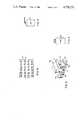
- FIG. 1is a side cross-sectional view of the container in accordance with the invention shown with temporary connectors and permanent connectors assembled therein after having effected a field restoration and showing the two fiber optic cables, i.e., the severed as well as the other cable which connects the one container to the other container extending therefrom;
- FIG. 2is a top plan view of the container of FIG. 1 shown with the permanent connectors mounted on the panel as well as the temporary connectors, and with only one fiber connected to one of the permanent connectors and no fibers connected to the temporary connectors for ease of understanding, and with the lid of the container, in partial view, shown open;
- FIG. 3is a front view of the mounting panel employed in the container according to the invention shown with the adapters mounted thereon;
- FIGS. 4 and 5illustrate typical cleaning means employed in accordance with the invention
- FIG. 6illustrates schematically a typical cleaving tool which can be employed in accordance with the system of the invention.
- FIG. 7illustrates a side cross-sectional view of the preferred embodiment of the temporary connector in accordance with the invention.
- FIGS. 1 and 2A container 1 in accordance with the invention is shown in FIGS. 1 and 2 shown with a cable 3 which connects to another container 1 attached thereto and with a severed cable restored 4.
- the container 1includes therein an adapter panel 17 having adapters 19 arranged in a matrix thereon which adapters serve to interconnect permanent type connectors 7 to temporary connectors 21.
- a fiber optic cable 3 containing multiple sheathed optical fiber conductors 5is attached to the container 1 and extends thereinto at hermetic seal 9, and with a like hermetic seal 9 provided on the opposite end of the container for a severed fiber optic cable 4.
- the container 1also includes a number of vertical dividers 15 which serve the purpose, when removed by disattachment from latch 15a, of serving as a splice tray effectively permitting accurate sorting and arrangement of individual fibers 14 which come from a bundled arrangement of fibers 13 extending from the severed cable 4. This will facilitate the attachment to the temporary connectors 21 as well as maintain some semblance of order when the restoration system is employed.
- the containerincludes a lid 1a which when closed is hermetically sealed by hermetic seals 11 (shown in FIG. 1). It is noted that the hermetic seal arrangement can take various forms as will be readily apparent to those of ordinary skill in the art.
- the temporary connectors 21when employed to effect field restoration, will esch terminate an individual fiber 14 and connect it to its corresponding connector 7 and fiber on the other side of the panel 17.
- the kit or systemfurther comprises, as shown in FIGS. 4 and 5, a container of compressed air, a container of methanol, as well as sanitized wipes (not shown).
- the container of air 23serves to blow away dust from the ends of the fibers and the methanol container 25 serves as liquid supply to cleanse away any dirt adhering to the ends of the connectors, i.e., temporary connectors 21 when a fiber is terminated thereby.
- the systemalso includes a flush cleaving tool such as for example, that shown in FIG. 6.
- the flush cleaving tool shown in FIG. 6is illustrated schematically and is not intended to be limiting as to the specific structure configuration employed.
- a temporary connector 21having a fiber terminated thereby and with the fiber extending out the front end of the connector is inserted in the direction of arrow 35 between clamp surfaces 27.
- Spring biasing meansurges scoring disc 39a in the direction of arrow 39 to be in contact flush with the end of a ferrule of a temporary connector for scoring a fiber extending therefrom.
- the fiber extending from the end of the temporary connectoris also seized by clamp surfaces 29 which move in the direction of vertical arrow 31 and in operation, when it is desired to flush cleave the fiber with the end of the ferrule of the connector, the scoring wheel 39a is moved in the direction of arrow 37 and thereafter the fiber is tensioned, alternatively, also simultaneously, in the direction of arrows 33 to cause flush cleaving as a result of the separation force exerted upon the scored fiber.
- a cutting of the fiberis not necessary and a flush cleave with a smooth flat surface is achieved.
- the connector 21is shown in FIG. 7 and it comprises a ceramic ferrule 101 having a passageway 109, 111 extending therethrough with a narrower portion 109 sized to snugly receive a buffer stripped fiber therein and a wider portion 111 which serves as a guide channel through ramp surfaces 113 to guide the fiber through and into the passage 109 to extend out the front end thereof.
- the passageway 109is sized to receive a buffer stripped fiber such that a predetermined amount of buffer material can be stripped from a fiber when inserted in the connector.
- the ramp surface 113serves as a stop to the buffer covered portion and as a guide for precise positioning of the fiber.
- the ceramic ferrule 101is supported in a press-fit engagement within a front body 114.
- Front body 114includes a passageway 115 extending therethrough which is coextensive with passageway 109, 111 in the ceramic ferrule 101.
- Supported on the front body 114is a key member 103 which includes a key mechanism 105 for the purpose of ensuring the same relative rotational position of the connector member when connected to an adapter in the event that a connection and reconnection needs to be effected thus, preventing scarring of the face of the fiber extending flush at the front end of the ferrule 101.
- a coupling nut 107 of conventional constructionis mounted on the front body 14 as shown therein. This coupling nut 107 combines with a conventional washer 107a to provide the means for attaching the connector to an adapter, i.e., adapters 19, for connection to a compatible connector, i.e. connectors 7.
- the front body 114includes the passageway 115 which is coextensive will passageway 109, 111, and which includes a sloped ramp surface 121 which serves as a biasing means as will be explained hereinafter. Furthermore, a threaded inner wall portion 125 serves to engage the fiber chuck 127 which will be discussed also hereinafter.
- Fiber chuck 127includes a passageway 117 extending therethrough which opens at the front and rear ends of the chuck 127. At the front end it includes clamp fingers 119 which serve to seize a fiber when the chuck member 127 is threaded at threads 123 fully into the front body 114.
- the walls of passageway 117 which extends through the rear body portion and out the rear end of the chuck member 127are preferably coated with a lubricating material, more preferably a PTFE polymer such as is conventionally available under the trade name TeflonTM.
- the chuck 127In use in temporarily repairing fiber optic cables, the chuck 127 is partially threaded at threads 23 to the front body 114, and a fiber having a predetermined length of buffer material stripped therefrom is inserted from the rear of the chuck member 127 through the chuck member passageway 117 into passageway 111 and through passageway 109 so that the fiber stripped of buffer material extends out the front of the ferrule 101.
- the portion of the fiber not stripped of bufferabuts at sloped wall portion 113 which serves as a stop.
- threading of the chuck member 127is continued until walls 121 engage the spring fingers 119 at the front end thereof and are thereby forced to close onto the buffer covered fiber to securely hold the fiber at that point. Tightening is conducted to a finger pressure level.
- the fiberis cleaved flush with the end of the ferrule by the tool illustrated in FIG. 6, and the assembly is ready for connection to the matable connector 7 mounted on panel 17 through adapters 19.
- flush cleaving methodcan be conducted, for example as in the method disclosed in U.S. Application Ser. No. 474,099 which was filed Mar. 10, 1983 and which is now allowed.
- the matable connectors 7can be of conventional construction or alternatively can be of the improved construction illustrated in copending U.S. Application Ser. No. 892,976 which was filed Aug. 4, 1986.
Landscapes
- Physics & Mathematics (AREA)
- General Physics & Mathematics (AREA)
- Optics & Photonics (AREA)
- Mechanical Coupling Of Light Guides (AREA)
Abstract
Description
Claims (8)
Priority Applications (1)
| Application Number | Priority Date | Filing Date | Title |
|---|---|---|---|
| US06/921,292US4728171A (en) | 1986-10-20 | 1986-10-20 | System for use in temporary repair of multiple fiber cable |
Applications Claiming Priority (1)
| Application Number | Priority Date | Filing Date | Title |
|---|---|---|---|
| US06/921,292US4728171A (en) | 1986-10-20 | 1986-10-20 | System for use in temporary repair of multiple fiber cable |
Publications (1)
| Publication Number | Publication Date |
|---|---|
| US4728171Atrue US4728171A (en) | 1988-03-01 |
Family
ID=25445219
Family Applications (1)
| Application Number | Title | Priority Date | Filing Date |
|---|---|---|---|
| US06/921,292Expired - LifetimeUS4728171A (en) | 1986-10-20 | 1986-10-20 | System for use in temporary repair of multiple fiber cable |
Country Status (1)
| Country | Link |
|---|---|
| US (1) | US4728171A (en) |
Cited By (28)
| Publication number | Priority date | Publication date | Assignee | Title |
|---|---|---|---|---|
| US4846565A (en)* | 1988-06-10 | 1989-07-11 | Gte Products Corporation | Emergency preterminated cable apparatus |
| US4848870A (en)* | 1988-04-06 | 1989-07-18 | Raychem Corporation | Optical fiber jaw connector |
| US4887875A (en)* | 1986-10-20 | 1989-12-19 | Amphenol Corporation | Fiber optic connector for use in temporary repair of multiple fiber cable |
| EP0349290A1 (en)* | 1988-06-29 | 1990-01-03 | BRITISH TELECOMMUNICATIONS public limited company | Patch panel |
| US4958905A (en)* | 1989-06-19 | 1990-09-25 | Tynes Arthur R | Method and apparatus for forming high strength splices in optical fibers |
| US5016962A (en)* | 1990-03-19 | 1991-05-21 | Raynet Corporation | Method of repairing an optical fiber |
| US5093885A (en)* | 1990-07-11 | 1992-03-03 | Adc Telecommunications, Inc. | Fiber optic connector module |
| US5107536A (en)* | 1991-04-22 | 1992-04-21 | Hughes Aircraft Company | Fiber optic crimp terminus and method of terminating an optical fiber using same |
| US5111520A (en)* | 1990-05-16 | 1992-05-05 | Hirose Electric Co., Ltd. | Optical fiber connector terminal |
| US5179618A (en)* | 1990-07-11 | 1993-01-12 | Adc Telecommunications, Inc. | Fiber optic connector module |
| US5185837A (en)* | 1991-04-23 | 1993-02-09 | Daiichi Denshi Kogyo Kabushiki Kaisha | Optical fiber connector including flexible fiber holding unit |
| US5201019A (en)* | 1991-07-15 | 1993-04-06 | Amphenol Corporation | Fiber optic splice connection and a method of making same |
| US5337385A (en)* | 1991-03-01 | 1994-08-09 | The Whitaker Corporation | Optical waveguide terminating device |
| US5390270A (en)* | 1989-11-28 | 1995-02-14 | Kel Corporation | Optical fiber ferrule assemblies |
| US5418874A (en)* | 1994-01-19 | 1995-05-23 | At&T Corp. | Force transfer system for an optical fiber connector |
| US5432875A (en)* | 1993-02-19 | 1995-07-11 | Adc Telecommunications, Inc. | Fiber optic monitor module |
| CN1040254C (en)* | 1992-01-28 | 1998-10-14 | 美国电话及电报公司 | Restoration kit for communications cable |
| US5898129A (en)* | 1996-05-23 | 1999-04-27 | The Siemon Company | Rack mountable cable distribution enclosure |
| USRE37489E1 (en)* | 1989-07-31 | 2002-01-01 | Adc Telecommunications, Inc. | Optical fiber distribution frame |
| US6382845B1 (en) | 1999-03-02 | 2002-05-07 | Ameritech Corporation | Fiber optic patch kit and method for using same |
| US6454462B2 (en) | 2000-04-18 | 2002-09-24 | Kings Electronics Co., Inc. | HDTV camera cable connector |
| US20060056769A1 (en)* | 2004-09-10 | 2006-03-16 | Khemakhem M Hamed A | Hybrid fiber/copper connector system and method |
| US20060233496A1 (en)* | 2005-04-15 | 2006-10-19 | Khemakhem M Hamed A | Hybrid fiber/copper connector system and method |
| US20070297745A1 (en)* | 2006-06-21 | 2007-12-27 | Thomas Moriarty | Optical connector |
| US20080124031A1 (en)* | 2006-11-29 | 2008-05-29 | Jarrod Scadden | Hybrid fiber/copper connector system and method |
| US20080124030A1 (en)* | 2006-11-29 | 2008-05-29 | Jarrod Scadden | Hybrid fiber/copper connector system and method |
| US20090269011A1 (en)* | 2007-11-30 | 2009-10-29 | Jarrod Scadden | Hybrid fiber/copper connector system and method |
| US20150086166A1 (en)* | 2012-03-19 | 2015-03-26 | Brian D. Coate | Apparatus and method for splicing all-dielectric self-supporting fiber optic cable |
Citations (10)
| Publication number | Priority date | Publication date | Assignee | Title |
|---|---|---|---|---|
| US4279466A (en)* | 1978-02-21 | 1981-07-21 | Bunker Ramo Corporation | Hermaphroditic fiber optic connector |
| US4319951A (en)* | 1980-04-29 | 1982-03-16 | Gk Technologies, Incorporated | Fiber organizer for splice cases and terminals |
| US4359262A (en)* | 1980-06-30 | 1982-11-16 | Northern Telecom Limited | Tray for organizing optical fiber splices and enclosures embodying such trays |
| US4614401A (en)* | 1983-06-10 | 1986-09-30 | Times Fiber Communications, Inc. | Optical fiber connector |
| US4623156A (en)* | 1984-01-31 | 1986-11-18 | Raychem Corporation | Optical fiber chuck |
| US4629284A (en)* | 1983-03-11 | 1986-12-16 | Alliance Technique Industrielle | Method and apparatus for connecting optical fibers |
| US4648168A (en)* | 1983-12-19 | 1987-03-10 | N.V. Raychem S.A. | Optical fibre breakout |
| US4666240A (en)* | 1985-02-01 | 1987-05-19 | Amp Incorporated | Splice organizer for optical cable splices |
| US4685764A (en)* | 1985-02-01 | 1987-08-11 | Amp Incorporated | Splice organizer for optical cable splices |
| US4687289A (en)* | 1985-09-17 | 1987-08-18 | Brintec Corporation | Fiberoptic splice organizer |
- 1986
- 1986-10-20USUS06/921,292patent/US4728171A/ennot_activeExpired - Lifetime
Patent Citations (10)
| Publication number | Priority date | Publication date | Assignee | Title |
|---|---|---|---|---|
| US4279466A (en)* | 1978-02-21 | 1981-07-21 | Bunker Ramo Corporation | Hermaphroditic fiber optic connector |
| US4319951A (en)* | 1980-04-29 | 1982-03-16 | Gk Technologies, Incorporated | Fiber organizer for splice cases and terminals |
| US4359262A (en)* | 1980-06-30 | 1982-11-16 | Northern Telecom Limited | Tray for organizing optical fiber splices and enclosures embodying such trays |
| US4629284A (en)* | 1983-03-11 | 1986-12-16 | Alliance Technique Industrielle | Method and apparatus for connecting optical fibers |
| US4614401A (en)* | 1983-06-10 | 1986-09-30 | Times Fiber Communications, Inc. | Optical fiber connector |
| US4648168A (en)* | 1983-12-19 | 1987-03-10 | N.V. Raychem S.A. | Optical fibre breakout |
| US4623156A (en)* | 1984-01-31 | 1986-11-18 | Raychem Corporation | Optical fiber chuck |
| US4666240A (en)* | 1985-02-01 | 1987-05-19 | Amp Incorporated | Splice organizer for optical cable splices |
| US4685764A (en)* | 1985-02-01 | 1987-08-11 | Amp Incorporated | Splice organizer for optical cable splices |
| US4687289A (en)* | 1985-09-17 | 1987-08-18 | Brintec Corporation | Fiberoptic splice organizer |
Cited By (67)
| Publication number | Priority date | Publication date | Assignee | Title |
|---|---|---|---|---|
| US4887875A (en)* | 1986-10-20 | 1989-12-19 | Amphenol Corporation | Fiber optic connector for use in temporary repair of multiple fiber cable |
| US4848870A (en)* | 1988-04-06 | 1989-07-18 | Raychem Corporation | Optical fiber jaw connector |
| US4846565A (en)* | 1988-06-10 | 1989-07-11 | Gte Products Corporation | Emergency preterminated cable apparatus |
| EP0349290A1 (en)* | 1988-06-29 | 1990-01-03 | BRITISH TELECOMMUNICATIONS public limited company | Patch panel |
| WO1990000261A1 (en)* | 1988-06-29 | 1990-01-11 | British Telecommunications Public Limited Company | Patch panel |
| US5011257A (en)* | 1988-06-29 | 1991-04-30 | British Telecommunications Public Limited Company | Optical fiber patch panel |
| US4958905A (en)* | 1989-06-19 | 1990-09-25 | Tynes Arthur R | Method and apparatus for forming high strength splices in optical fibers |
| USRE37489E1 (en)* | 1989-07-31 | 2002-01-01 | Adc Telecommunications, Inc. | Optical fiber distribution frame |
| US5390270A (en)* | 1989-11-28 | 1995-02-14 | Kel Corporation | Optical fiber ferrule assemblies |
| US5016962A (en)* | 1990-03-19 | 1991-05-21 | Raynet Corporation | Method of repairing an optical fiber |
| US5111520A (en)* | 1990-05-16 | 1992-05-05 | Hirose Electric Co., Ltd. | Optical fiber connector terminal |
| US5093885A (en)* | 1990-07-11 | 1992-03-03 | Adc Telecommunications, Inc. | Fiber optic connector module |
| US5179618A (en)* | 1990-07-11 | 1993-01-12 | Adc Telecommunications, Inc. | Fiber optic connector module |
| US5337385A (en)* | 1991-03-01 | 1994-08-09 | The Whitaker Corporation | Optical waveguide terminating device |
| US5107536A (en)* | 1991-04-22 | 1992-04-21 | Hughes Aircraft Company | Fiber optic crimp terminus and method of terminating an optical fiber using same |
| US5185837A (en)* | 1991-04-23 | 1993-02-09 | Daiichi Denshi Kogyo Kabushiki Kaisha | Optical fiber connector including flexible fiber holding unit |
| US5201019A (en)* | 1991-07-15 | 1993-04-06 | Amphenol Corporation | Fiber optic splice connection and a method of making same |
| CN1040254C (en)* | 1992-01-28 | 1998-10-14 | 美国电话及电报公司 | Restoration kit for communications cable |
| US5432875A (en)* | 1993-02-19 | 1995-07-11 | Adc Telecommunications, Inc. | Fiber optic monitor module |
| US5418874A (en)* | 1994-01-19 | 1995-05-23 | At&T Corp. | Force transfer system for an optical fiber connector |
| US5898129A (en)* | 1996-05-23 | 1999-04-27 | The Siemon Company | Rack mountable cable distribution enclosure |
| US5945633A (en)* | 1996-05-23 | 1999-08-31 | The Siemon Company | Rack mountable cable distribution enclosure having an angled adapter plate bracket |
| US6353183B1 (en) | 1996-05-23 | 2002-03-05 | The Siemon Company | Adapter plate for use with cable adapters |
| US20070086722A1 (en)* | 1999-03-02 | 2007-04-19 | Gould Glen Edward | Fiber optic patch kit and method for using the same |
| US6382845B1 (en) | 1999-03-02 | 2002-05-07 | Ameritech Corporation | Fiber optic patch kit and method for using same |
| US20020146220A1 (en)* | 1999-03-02 | 2002-10-10 | Ameritech Corporation | Fiber optic patch kit and method for using same |
| US6905263B2 (en) | 1999-03-02 | 2005-06-14 | Sbc Properties, L.P. | Fiber optic patch kit and method for using same |
| US20050265680A1 (en)* | 1999-03-02 | 2005-12-01 | Sbc Properties, L.P. | Fiber optic patch kit and method for using same |
| US7769267B2 (en) | 1999-03-02 | 2010-08-03 | At&T Intellectual Property I, L.P. | Fiber optic patch kit and method for using the same |
| US20080292252A1 (en)* | 1999-03-02 | 2008-11-27 | Glen Edward Gould | Fiber Optic Patch Kit and Method for Using the Same |
| US7379649B2 (en) | 1999-03-02 | 2008-05-27 | At&T Knowledge Ventures, Lp | Fiber optic patch kit and method for using the same |
| US7171101B2 (en) | 1999-03-02 | 2007-01-30 | Sbc Properties, L.P. | Fiber optic patch kit and method for using same |
| US6454462B2 (en) | 2000-04-18 | 2002-09-24 | Kings Electronics Co., Inc. | HDTV camera cable connector |
| KR101225891B1 (en)* | 2004-09-10 | 2013-01-24 | 에이디씨 텔레커뮤니케이션스 인코포레이티드 | Hybrid fiber/copper connector system and method |
| US7520678B2 (en) | 2004-09-10 | 2009-04-21 | Adc Telecommunications, Inc. | Hybrid fiber/copper connector system and method |
| US20070263961A1 (en)* | 2004-09-10 | 2007-11-15 | Adc Telecommunications, Inc. | Hybrid fiber/copper connector system and method |
| US20100040331A1 (en)* | 2004-09-10 | 2010-02-18 | Adc Telecommunications, Inc. | Hybrid fiber/copper connector system and method |
| JP2008516570A (en)* | 2004-09-10 | 2008-05-15 | エーディーシー テレコミュニケーションズ,インコーポレイティド | Optical fiber / copper wire hybrid connector apparatus and method |
| US20060056769A1 (en)* | 2004-09-10 | 2006-03-16 | Khemakhem M Hamed A | Hybrid fiber/copper connector system and method |
| US8147147B2 (en) | 2004-09-10 | 2012-04-03 | Adc Telecommunications, Inc. | Hybrid fiber/copper connector system and method |
| JP4851459B2 (en)* | 2004-09-10 | 2012-01-11 | エーディーシー テレコミュニケーションズ,インコーポレイティド | Optical fiber / copper wire hybrid connector apparatus and method |
| CN100523893C (en)* | 2004-09-10 | 2009-08-05 | Adc电信公司 | System and method for hybrid fiber/copper connector |
| US7213975B2 (en) | 2004-09-10 | 2007-05-08 | Adc Telecommunications, Inc. | Hybrid fiber/copper connector system and method |
| AU2005292491B2 (en)* | 2004-09-10 | 2011-04-21 | Adc Telecommunications, Inc. | Hybrid fiber/copper connector system and method |
| WO2006039084A1 (en)* | 2004-09-10 | 2006-04-13 | Adc Telecommunications, Inc. | Hybrid fiber/copper connector system and method |
| US20060233496A1 (en)* | 2005-04-15 | 2006-10-19 | Khemakhem M Hamed A | Hybrid fiber/copper connector system and method |
| US20090180739A1 (en)* | 2005-04-15 | 2009-07-16 | Adc Telecommunications, Inc. | Hybrid fiber/copper connector system and method |
| US7393144B2 (en) | 2005-04-15 | 2008-07-01 | Adc Telecommunications, Inc. | Hybrid fiber/copper connector system and method |
| US7798725B2 (en) | 2005-04-15 | 2010-09-21 | Adc Telecommunications, Inc. | Hybrid fiber/copper connector system and method |
| WO2006113154A1 (en)* | 2005-04-15 | 2006-10-26 | Adc Telecommunications, Inc. | Hybrid fiber/copper connector system and method |
| US7905665B2 (en) | 2006-06-21 | 2011-03-15 | Firecomms Limited | Optical connector |
| US20070297745A1 (en)* | 2006-06-21 | 2007-12-27 | Thomas Moriarty | Optical connector |
| US7597485B2 (en)* | 2006-06-21 | 2009-10-06 | Firecomms Limited | Optical connector |
| US8113722B2 (en) | 2006-11-29 | 2012-02-14 | Adc Telecommunications, Inc. | Hybrid fiber/copper connector system and method |
| US20080124031A1 (en)* | 2006-11-29 | 2008-05-29 | Jarrod Scadden | Hybrid fiber/copper connector system and method |
| US7481585B2 (en) | 2006-11-29 | 2009-01-27 | Adc Telecommunications, Inc. | Hybrid fiber/copper connector system and method |
| US20090238519A1 (en)* | 2006-11-29 | 2009-09-24 | Adc Telecommunication, Inc. | Hybrid fiber/copper connector system and method |
| US20080124030A1 (en)* | 2006-11-29 | 2008-05-29 | Jarrod Scadden | Hybrid fiber/copper connector system and method |
| US8113720B2 (en) | 2006-11-29 | 2012-02-14 | Adc Telecommunications, Inc. | Hybrid fiber/copper connector system and method |
| US7490994B2 (en) | 2006-11-29 | 2009-02-17 | Adc Telecommunications, Inc. | Hybrid fiber/copper connector system and method |
| US20090269011A1 (en)* | 2007-11-30 | 2009-10-29 | Jarrod Scadden | Hybrid fiber/copper connector system and method |
| US8083416B2 (en) | 2007-11-30 | 2011-12-27 | Adc Telecommunications, Inc. | Hybrid fiber/copper connector system and method |
| US8678666B2 (en) | 2007-11-30 | 2014-03-25 | Adc Telecommunications, Inc. | Hybrid fiber/copper connector system and method |
| US20150086166A1 (en)* | 2012-03-19 | 2015-03-26 | Brian D. Coate | Apparatus and method for splicing all-dielectric self-supporting fiber optic cable |
| US20160154181A1 (en)* | 2012-03-19 | 2016-06-02 | Brian D. Coate | Apparatus and method for splicing all-dielectric self-supporting fiber optic cable |
| US10379308B2 (en)* | 2012-03-19 | 2019-08-13 | Brian D. Coate | Apparatus and method for splicing all-dielectric self-supporting fiber optic cable |
| US10585260B2 (en)* | 2012-03-19 | 2020-03-10 | Brian D. Coate | Apparatus and method for splicing all-dielectric self-supporting fiber optic cable |
Similar Documents
| Publication | Publication Date | Title |
|---|---|---|
| US4728171A (en) | System for use in temporary repair of multiple fiber cable | |
| US11555968B2 (en) | Optical fiber connection system | |
| US20190041588A1 (en) | Field installable optical fiber connector for fiber optic cables with rigid strength members | |
| CN102057308B (en) | Field-terminable fiber optic connectors with splice elements | |
| CN100480759C (en) | Optical connectors and fiber optic connection systems | |
| EP0524079A1 (en) | Fiber optic splice connection | |
| CN100465678C (en) | Reversible optical fiber connector | |
| US4887875A (en) | Fiber optic connector for use in temporary repair of multiple fiber cable | |
| US3923371A (en) | Optical fibre connectors | |
| KR100944702B1 (en) | Field-accessible fiber optic connectors with splice elements | |
| US7991259B2 (en) | Fiber optic patch kit and method for using same | |
| KR19990028510A (en) | Fiber optic connector for fiber with cleaved and beveled ends | |
| KR19990028509A (en) | Uncoated Fiber Connector | |
| WO2006004328A1 (en) | Optical connector | |
| CN101297224A (en) | Optical fiber connector, optical fiber distribution device, and optical fiber termination platform for optical fiber connector | |
| US4699460A (en) | Method and apparatus for repairing fiber optic cable | |
| US6351593B1 (en) | Hermetically sealed connectors and feed-throughs for fiber optic cables and method for effecting hermetic seals for such cables | |
| KR19990028512A (en) | Fiber optic connector | |
| CN102713704A (en) | Fiber optic connector of a fiber optic connection termination system | |
| US7264401B2 (en) | Panel-mountable optical fiber splice | |
| US7537398B2 (en) | Optical fibre splice connector | |
| JP5160706B2 (en) | Fiber optic cable terminal equipment | |
| US7014370B2 (en) | Bare fiber optical connecting devices | |
| EP0536206A1 (en) | Optical connector. | |
| US5018823A (en) | Single channel high power fiber optic connector |
Legal Events
| Date | Code | Title | Description |
|---|---|---|---|
| AS | Assignment | Owner name:ALLIED CORPORATION, COLUMBIA ROAD AND PARK AVENUE, Free format text:ASSIGNMENT OF ASSIGNORS INTEREST.;ASSIGNORS:SCHOFIELD, PHILIP W.;DUDA, DONALD W.;CHANG, PETER;REEL/FRAME:004667/0135;SIGNING DATES FROM 19870112 TO 19870113 Owner name:ALLIED CORPORATION, COLUMBIA ROAD AND PARK AVENUE, Free format text:ASSIGNMENT OF ASSIGNORS INTEREST.;ASSIGNOR:BERGMAN, DARRIN J.;REEL/FRAME:004667/0137 Effective date:19870112 Owner name:ALLIED CORPORATION, A CORP. OF NEW YORK,NEW YORK Free format text:ASSIGNMENT OF ASSIGNORS INTEREST;ASSIGNORS:SCHOFIELD, PHILIP W.;DUDA, DONALD W.;CHANG, PETER;SIGNING DATES FROM 19870112 TO 19870113;REEL/FRAME:004667/0135 Owner name:ALLIED CORPORATION, A CORP. OF NEW YORK,NEW JERSEY Free format text:ASSIGNMENT OF ASSIGNORS INTEREST;ASSIGNOR:BERGMAN, DARRIN J.;REEL/FRAME:004667/0137 Effective date:19870112 | |
| AS | Assignment | Owner name:CANADIAN IMPERIAL BANK OF COMMERCE, NEW YORK AGENC Free format text:SECURITY INTEREST;ASSIGNOR:AMPHENOL CORPORATION;REEL/FRAME:004879/0030 Effective date:19870515 | |
| AS | Assignment | Owner name:AMPHENOL CORPORATION, LISLE, ILLINOIS A CORP. OF D Free format text:ASSIGNMENT OF ASSIGNORS INTEREST.;ASSIGNOR:ALLIED CORPORATION, A CORP. OF NY;REEL/FRAME:004844/0850 Effective date:19870602 Owner name:AMPHENOL CORPORATION, A CORP. OF DE, ILLINOIS Free format text:ASSIGNMENT OF ASSIGNORS INTEREST;ASSIGNOR:ALLIED CORPORATION, A CORP. OF NY;REEL/FRAME:004844/0850 Effective date:19870602 | |
| FEPP | Fee payment procedure | Free format text:PAYOR NUMBER ASSIGNED (ORIGINAL EVENT CODE: ASPN); ENTITY STATUS OF PATENT OWNER: LARGE ENTITY | |
| STCF | Information on status: patent grant | Free format text:PATENTED CASE | |
| FPAY | Fee payment | Year of fee payment:4 | |
| AS | Assignment | Owner name:BANKERS TRUST COMPANY, AS AGENT Free format text:SECURITY INTEREST;ASSIGNOR:AMPHENOL CORPORATION, A CORPORATION OF DE;REEL/FRAME:006035/0283 Effective date:19911118 | |
| AS | Assignment | Owner name:AMPHENOL CORPORATION A CORP. OF DELAWARE Free format text:RELEASED BY SECURED PARTY;ASSIGNOR:CANADIAN IMPERIAL BANK OF COMMERCE;REEL/FRAME:006147/0887 Effective date:19911114 | |
| AS | Assignment | Owner name:AMPHENOL CORPORATION, CONNECTICUT Free format text:RELEASE BY SECURED PARTY;ASSIGNOR:BANKERS TRUST COMPANY;REEL/FRAME:007317/0148 Effective date:19950104 | |
| FPAY | Fee payment | Year of fee payment:8 | |
| REFU | Refund | Free format text:REFUND - PAYMENT OF MAINTENANCE FEE, 8TH YEAR, LARGE ENTITY (ORIGINAL EVENT CODE: R184); ENTITY STATUS OF PATENT OWNER: LARGE ENTITY | |
| FPAY | Fee payment | Year of fee payment:12 |