US4726562A - Apparatus for casting an anchor in a concrete unit - Google Patents
Apparatus for casting an anchor in a concrete unitDownload PDFInfo
- Publication number
- US4726562A US4726562AUS06/889,060US88906086AUS4726562AUS 4726562 AUS4726562 AUS 4726562AUS 88906086 AUS88906086 AUS 88906086AUS 4726562 AUS4726562 AUS 4726562A
- Authority
- US
- United States
- Prior art keywords
- anchor
- gripping
- mandrel
- recess
- gripper elements
- Prior art date
- Legal status (The legal status is an assumption and is not a legal conclusion. Google has not performed a legal analysis and makes no representation as to the accuracy of the status listed.)
- Expired - Fee Related
Links
- 239000004567concreteSubstances0.000titleclaimsabstractdescription36
- 238000005266castingMethods0.000titleclaimsabstractdescription16
- 239000011800void materialSubstances0.000claimsabstractdescription44
- 238000009415formworkMethods0.000claimsabstractdescription23
- 230000000694effectsEffects0.000claims2
- 238000000926separation methodMethods0.000claims2
- 230000000717retained effectEffects0.000claims1
- 210000003128headAnatomy0.000description30
- 238000000034methodMethods0.000description7
- 239000011178precast concreteSubstances0.000description6
- 239000010959steelSubstances0.000description5
- 229910000831SteelInorganic materials0.000description4
- 230000002093peripheral effectEffects0.000description2
- 229910000838Al alloyInorganic materials0.000description1
- 229910000851Alloy steelInorganic materials0.000description1
- 229910001294Reinforcing steelInorganic materials0.000description1
- 230000009471actionEffects0.000description1
- 238000004140cleaningMethods0.000description1
- 238000006073displacement reactionMethods0.000description1
- 238000003780insertionMethods0.000description1
- 230000037431insertionEffects0.000description1
- 230000008439repair processEffects0.000description1
- 230000004044responseEffects0.000description1
- 230000007480spreadingEffects0.000description1
Images

Classifications
- E—FIXED CONSTRUCTIONS
- E04—BUILDING
- E04G—SCAFFOLDING; FORMS; SHUTTERING; BUILDING IMPLEMENTS OR AIDS, OR THEIR USE; HANDLING BUILDING MATERIALS ON THE SITE; REPAIRING, BREAKING-UP OR OTHER WORK ON EXISTING BUILDINGS
- E04G21/00—Preparing, conveying, or working-up building materials or building elements in situ; Other devices or measures for constructional work
- E04G21/14—Conveying or assembling building elements
- E04G21/142—Means in or on the elements for connecting same to handling apparatus
- B—PERFORMING OPERATIONS; TRANSPORTING
- B28—WORKING CEMENT, CLAY, OR STONE
- B28B—SHAPING CLAY OR OTHER CERAMIC COMPOSITIONS; SHAPING SLAG; SHAPING MIXTURES CONTAINING CEMENTITIOUS MATERIAL, e.g. PLASTER
- B28B23/00—Arrangements specially adapted for the production of shaped articles with elements wholly or partly embedded in the moulding material; Production of reinforced objects
- B28B23/005—Arrangements specially adapted for the production of shaped articles with elements wholly or partly embedded in the moulding material; Production of reinforced objects with anchoring or fastening elements for the shaped articles
Definitions
- the present inventionrelates to apparatus and methods for casting anchors in concrete units and, more particularly, for apparatus and methods for casting anchors in conrete units such that the anchor head is recessed within a void formed in the cast unit.
- precast concrete unitsof various shapes designed to facilitate their interlocking engagement when set into place. These precast concrete units may range in weight from several hundred pounds to several tons.
- the unitsare cast with pickup bolts or anchors at predetermined locations.
- the anchorstypically comprise a length of steel rod with a flared head and foot.
- the flared footmay be tied to an adjacent piece of reinforcing steel, and the flared head is positioned within a void or recess so that it is spaced from the adjacent outer surface of the unit.
- a precast concrete unit having the aforementioned anchorscan be picked up and handled relatively easily by attaching the anchors to the cable of a hoist.
- the cablemay be attached to lifting eyes which comprises a notched ball shaped to fit within the recess and engage the anchor head, and a large eye which is connected to a hook or cable.
- lifting eye of this typeis shown in Haeussler et al. U.S. Pat. No. 4,398,762.
- Haeussler U.S. Pat. No. 4,296,909One device for casting an anchor in a concrete unit is shown in Haeussler U.S. Pat. No. 4,296,909, and includes a pair of quarter-spherical steel elements which meet to form an opening sized to receive the shank of the anchor, and include an interior cavity recess shaped to receive the anchor head.
- the spherical elementsare pivotally attached to a bridge piece which in turn receives a threaded mounting rod.
- An anchoris inserted between the spherical elements and the rod is bolted to the formwork.
- the pressure of the formwork against the spherical elements and the bridge piecemaintains them in a coplanar relationship to each other while the concrete is cast and hardens.
- the formworkis separated from the cast unit, and the device is disengaged from the anchor head by rocking the rod back and forth, which alternately disengages each of the quarter-spherical elements.
- a hemispherical steel recess plugis attached to the formwork and includes a cylindrical recess sized to receive the anchor head.
- a split rubber ringis placed about the shank of the anchor just below the head and is sized to seal the cylindrical recess to prevent the entry of concrete during the casting process.
- the recess plugis made of rubber and includes a cylindrical opening sized to receive the shank of the anchor.
- the cylindrical openingcommunicates with an interior chamber shaped to receive the anchor head.
- This recess plugis attached to the formwork and the anchor is forced through the resilient cylindrical opening of the recess plug.
- a disadvantage with this particular deviceis that there is a likelihood that the rubber recess plugs may be damaged after repeated deformation resulting from the forced insertion of the anchor head through the cylindrical opening. There is also a possibility of concrete leakage into the interior chamber in the event that the opening is not sized properly.
- a disadvantage with all of the aforementioned devicesis that the attachment of the anchor to the device, and the subsequent removal of the device from the anchor cast into the unit, are manually intensive, requiring an undesirable number of manipulative steps. This requirement for several manipulative steps raises the overall cost of fabricating the precast concrete unit. Accordingly, there is a need for an apparatus and method for casting an anchor in a concrete unit which is reliable, which minimizes the leakage of concrete into the void formed about the anchor head, and which minimizes the number of manipulative steps required for attachment of the anchor to the device and the subsequent removal of the device from the anchor cast in the unit.
- the present inventionis an apparatus and method for casting an anchor in a concrete unit in which the anchor is readily attachable to the apparatus prior to casting and the apparatus is easily removed from the anchor head after the unit has been cast.
- the apparatusis integral with the formwork of the precast unit, and need not be separated from the formwork prior to being separated from the cast unit. Accordingly, the step of reattaching the device to the formwork, required with prior art devices, is eliminated.
- the apparatusincludes a mandrel having a recess at its outer end surrounded by a plurality of gripper elements which are biased radially inwardly, a void former sleeve having a hemispherical outer end and a longitudinal bore receiving the mandrel, and a support sleeve having a longitudinal channel sized to receive the void former sleeve.
- the gripper elementsare easily deflected radially outwardly from the mandrel in response to the pressure exerted to insert the anchor head into the recess. Once the anchor has entered the recess, the gripper elements pivot radially inwardly to engage the shank of the anchor and retain the head within the recess.
- the recesspreferably includes a spring-loaded plunger which urges the anchor head against the gripper elements so that the anchor is maintained in a coaxial relationship with the mandrel.
- the bore of the void former sleeveis sized such that the gripper elements are prevented from pivoting radially outwardly when the mandrel is displaced within the sleeve. This relationship prevents the anchor from being released from the apparatus until the apparatus is disengaged from the cost unit.
- a cam rodextends outwardly from the mandrel and is received within an elongated, longitudinally-extending slot in the void former sleeve. The slot acts as a cam surface and the ends of the slot define limits of travel for the mandrel relative to the void former sleeve.
- the outer limit of travelallows the mandrel to extend outwardly from the bore a sufficient amount to allow the gripper fingers to be pivoted outwardly to receive the anchor head.
- the inner limit of travelallows the mandrel to be withdrawn into the bore of the void former sleeve to a point in which the outer end of the mandrel forms a continuous surface with the outer end of the void former sleeve.
- the support sleeveis adapted to be attached to the formwork for the precast unit and includes a spring-loaded detent pin at its end.
- the detent pinis positioned to extend through a detent slot formed in the void former sleeve and a detent recess formed in the mandrel when the mandrel and void former sleeve are positioned so that the mandrel is withdrawn into the void former sleeve and the void former sleeve is positioned such that the hemispherical outer end protrudes into the mold.
- the support sleeveincludes a retainer stud which engages a longitudinal groove in the former sleeve.
- the groovehas closed ends and the engagement prevents the former sleeve from inadvertently falling into the support sleeve.
- the method of the inventionis initiated by attaching the end of an anchor to the mandrel by inserting the anchor head into the recess.
- the mandrelis then withdrawn into the void former sleeve so that the gripper elements are prevented from pivoting radially outwardly, thereby locking the anchor within the recess.
- the void former sleevecan then be positioned within the support sleeve such that the hemispherical outer end protrudes from the formwork.
- the detent pinis then released to lock the void former sleeve and mandrel in position relative to the support sleeve. With the anchor and void former sleeve now in the proper position, the concrete casting process can be effected.
- the detent pinis disengaged from the void former sleeve and mandrel, and the void former sleeve is displaced relative to the support sleeve away from the cast concrete unit. This action causes the mandrel to be withdrawn from the bore of the void former sleeve. Once the cam rod reaches the stop in the cam rod slot, the resulting force causes the anchor head to be withdrawn from the recess in the mandrel.
- All of the principal components of the inventionmay be fabricated from steel or aluminum alloy, which provides a long useful life.
- the apparatusalso may be assembled or disassembled easily for cleaning or repair.
- an object of the present inventionto provide an apparatus and method for casting an anchor in a concrete unit in which the anchor can be attached to or removed from the apparatus with relatively few manipulative steps; an apparatus in which the attachment and removal operations can be performed with a small likelihood of damage to the apparatus or the jamming of its components; and an apparatus which can be made of highly wear-resistant components which provide a long, trouble-free life.
- FIG. 1is a perspective view of a precast concrete unit having a pair of anchors embedded in its upper surface;
- FIG. 2is a detail of FIG. 1, showing a perspective view of one of the anchors;
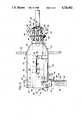
- FIG. 3is a side elevation of a preferred embodiment of the present invention, shown attached to formwork, and in which the support sleeve and formwork are in section;
- FIG. 4is an end elevation of the void former sleeve and mandrel of the apparatus of FIG. 3, in which the mandrel is shown retaining an anchor, shown in section;
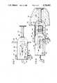
- FIG. 5is a side elevation of the void former sleeve of FIG. 3;
- FIG. 6is a side elevation of the mandrel of FIG. 3, in which a gripper element is shown exploded from the mandrel body;
- FIG. 7is a side elevation of the apparatus of FIG. 3, in which the mandrel is shown withdrawn into the void former sleeve;
- FIG. 8is a side elevation of the apparatus of FIG. 3, showing the void former sleeve retracted from a cast concrete unit and the mandrel disengaged from the anchor head, and in which two gripper elements are shown splayed in phantom.
- a precast concrete unitis plate-shaped and includes an outer peripheral surface 12.
- the upper peripheral surface 14includes two hemispherical recesses 16,18, each associated with an anchor 20.
- Each anchor 20is made from a section of steel rod and includes a flared head 22 and foot 24.
- the head 22protrudes from the bottoms of the recesses 16,18 so that the top portion of the head is slightly below the upper surface 14.
- the anchors 20are centered within the recesses 16,18 and can be grasped by pickup devices such as that shown in Hacussler et al. U.S. Pat. No. 4,398,762, the disclosure of which is incorporated herein by reference.
- Such concrete units 10are cast within formwork which supports the apparatus of the present invention, generally designated 26, shown attached to a formwork wall 28 in FIG. 3.
- the apparatus 28includes a cylindrical support sleeve 30 which is attached to the formwork wall 28 by weldments 32 and forms a central, longitudinal channel 34. Alternately, a threaded connection can also be made.
- a detent 36is attached to the sleeve 30 adjacent to its inward end and includes a cylindrical barrel 38 which receives a coil spring 40 seated within a chamber 42 and urges against a detent pin 44, having a rounded tip.
- the detent pin 44also includes a pair of handles 46 which protrude outwardly from the pin and are displaceable along opposing slots 48 formed in the barrel 38.
- the barrel 38is threaded into a nut 49 which, in turn, is welded to the outer surface of the sleeve 30.
- the pin 44extends through an opening 50 in the sleeve so that the tip of the pin protrudes into the channel 34.
- a retainer stud 51is threaded into a nut 52 attached to the sleeve 30 opposite the detent 36.
- the stud 51extends through a hole 53 in the sleeve 30 and into the channel 34.
- a void former sleevegenerally designated 54, includes cylindrical body 56 having a central, longitudinal bore 58 extending therethrough.
- the void former sleeve 54terminates in an outer end 60 having a truncated hemispherical shape.
- the body of the former sleeve 54includes forward and rearward detent slots 62,64, respectively which open into the central bore 58.
- the body 56also includes a pair of opposing cam slots 66, each of which includes forward and rearward rounded surfaces 68, 70 respectively.
- the body 56also includes an elongated groove 72 which extends parallel to the bore 58 and opposite the detent slots 62,64.
- the groove 72receives the stud 51 and is closed ended, so that the engagement of the stud 51 with the groove 72 defines limits of forward and rearward travel of the former sleeve 54 within the channel 34.
- a handle 73is threaded into the end of the body 56.
- a mandrelgenerally designated 74, includes an elongate, cylindrical body 76 having forward and rearward circumferential grooves 78,80 respectively.
- Groove 78includes a diametrically extending hole 82 which receives a cam rod 84 in a press fit.
- the cam rod 84extends outwardly from the mandrel body 76 and into the opposing cam slots 66 of the void former sleeve 56.
- the forward end 86 of the mandrel 74terminates in an arcuate surface 88 having a recess 90.
- the outer end 86includes a plurality of radially extending slots 92, each of which communicates with the recess 90 and receives a gripper element 94.
- Each gripper element 94includes an inwardly extending finger 96 which includes an interior gripping surface 98.
- the end of the gripper element 94 opposite the finger 96includes a rounded portion 100 which is received within a recess 102 formed in the body 76.
- the outer edge of each gripper elementincludes a notch 104 which is aligned with corresponding notches 106 formed in the outer end 86 of the mandrel 74, together forming a circumferential groove.
- the circumferential grooveseats an O-ring 108.
- the O-ringresiliently urges the gripper elements 94 to pivot radially inwardly so that the fingers 96 enter the recess 90.
- the O-ring 108is positioned so that each gripper element 94 pivots about its rounded portion 100.
- a spring-loaded plunger 110(see FIG. 6) is mounted within a bore 112 formed in the base of the recess 90.
- the plunger 110includes a bullet-nosed pin 114 having a flange 115 which is urged outwardly against a snap ring 116 by a helical extension spring 118, seated within the bore 112.
- the mandrelIn order to attach the anchor 20 to the mandrel 74, the mandrel is first displaced outwardly relative to the void former sleeve 54 by inserting one's finger 120 into the bore 58 and pushing the mandrel body 76 until the cam rod 84 engages the forward rounded edge 68, which acts as a stop for the forward travel of the mandrel 74. In this position, the portion of the mandrel 74 including the gripper elements 94 protrudes outwardly from the outer end 60 of the void former sleeve 54. The anchor head 22 is pressed against the outer surface 88 of the mandrel, which causes the gripper elements to be forced radially outwardly as shown in FIG. 3, which allows the anchor head to enter the recess 90.
- the pin 114urges the head outwardly so that the underside of the head 22 engages the interior gripping surfaces 98 of the gripper elements 94.
- the force exerted by the pin 114is sufficient to maintain the shank of the pin 20 in coaxial alignment with the cylindrical body 76 of the mandrel 74, but is not sufficient to spread the gripper elements 94 radially outwardly.
- the mandrel 74is withdrawn into the void former sleeve 54 until the cam rod 84 engages the rearward rounded edge 70 of the cam slot 66, which acts as a rearward limit of travel for the mandrel.
- the outer surface 88 of the mandrel 74forms a continuous, rounded surface with the hemispherical outer end 60 of the void former sleeve 54.
- the void former sleeveis now positioned within the support sleeve 30 such that the detent pin 44 extends through the rearward detent slot 64 and engages the rearward groove 80 of the mandrel 74.
- the mandrel 74is locked within the void former sleeve 54, and the void former sleeve is locked in position relative to the support sleeve 30 so that only the hemispherical outer end 60 protrudes from the formwork wall 28 into the mold.
- the bore 58is dimensioned such that, when the mandrel 74 is fully retracted within the bore, the gripper elements 94 are constrained from spreading radially outwardly and are held in an anchor-gripping position. With the apparatus 26 in position as shown in FIG. 7, the concrete unit can now be cast.
- the apparatus 26may now be disengaged from the concrete unit 10 and anchor 20, as shown in FIG. 8.
- the detent pin 44is withdrawn from the slot 64 and groove 80, and the user grabs the handle 73 to draw the void former sleeve 54 away from the concrete unit 10 along the support sleeve 30. Since the mandrel 74 still engages the anchor head 22, the mandrel remains in position relative to the concrete unit 10 and slides along the bore 58 until the cam rod 84 encounters the end 68 of the cam slot 66. At this time, the continued displacement of the void former sleeve 54 away from the concrete unit 10 causes the anchor head to be released from the recess 90 (FIG. 6) which causes the gripper elements 94 to spread redially outwardly from the body 76.
- the rearward movement of the void former sleeve 54is stopped when the detent pin 44 engages the forward detent slot 62.
- the formwork walls 28may now be removed from the outer surface 12 of the concrete unit 10, leaving the anchor heads 22 of the anchors 20 recessed within their respective hemispherical recesses as shown in FIGS. 2 and 8.
Landscapes
- Engineering & Computer Science (AREA)
- Architecture (AREA)
- Mechanical Engineering (AREA)
- Manufacturing & Machinery (AREA)
- Chemical & Material Sciences (AREA)
- Ceramic Engineering (AREA)
- Civil Engineering (AREA)
- Structural Engineering (AREA)
- Moulds, Cores, Or Mandrels (AREA)
- Manufacturing Of Tubular Articles Or Embedded Moulded Articles (AREA)
Abstract
Description
Claims (18)
Priority Applications (2)
| Application Number | Priority Date | Filing Date | Title |
|---|---|---|---|
| US06/889,060US4726562A (en) | 1986-07-22 | 1986-07-22 | Apparatus for casting an anchor in a concrete unit |
| FR8705921AFR2601987A1 (en) | 1986-07-22 | 1987-04-27 | APPARATUS AND METHOD FOR CASTING ANCHOR IN A CONCRETE BLOCK |
Applications Claiming Priority (1)
| Application Number | Priority Date | Filing Date | Title |
|---|---|---|---|
| US06/889,060US4726562A (en) | 1986-07-22 | 1986-07-22 | Apparatus for casting an anchor in a concrete unit |
Publications (1)
| Publication Number | Publication Date |
|---|---|
| US4726562Atrue US4726562A (en) | 1988-02-23 |
Family
ID=25394448
Family Applications (1)
| Application Number | Title | Priority Date | Filing Date |
|---|---|---|---|
| US06/889,060Expired - Fee RelatedUS4726562A (en) | 1986-07-22 | 1986-07-22 | Apparatus for casting an anchor in a concrete unit |
Country Status (2)
| Country | Link |
|---|---|
| US (1) | US4726562A (en) |
| FR (1) | FR2601987A1 (en) |
Cited By (31)
| Publication number | Priority date | Publication date | Assignee | Title |
|---|---|---|---|---|
| WO1991017031A1 (en)* | 1990-05-03 | 1991-11-14 | Pedershaab Maskinfabrik A/S | Method and apparatus for casting a body of concrete |
| US5123825A (en)* | 1988-03-12 | 1992-06-23 | Detec Fertigung Gmbh | Device for inserting transport anchors in forms for concrete parts |
| WO1994024390A1 (en)* | 1993-04-08 | 1994-10-27 | Alan H. Reid Pty. Ltd. | Edge lifting recess former and reinforcement system |
| US5535979A (en)* | 1993-05-10 | 1996-07-16 | Conac Limited | Apparatus for use in forming recesses in cast bodies |
| WO2000036248A1 (en)* | 1998-12-17 | 2000-06-22 | Dayton Superior Corporation | Anchor positioning insert |
| USD436674S1 (en) | 2000-02-04 | 2001-01-23 | Dayton Superior Corporation | Concrete anchor |
| USD437063S1 (en) | 2000-02-04 | 2001-01-30 | Dayton Superior Corporation | Concrete anchor including a pentagonal base |
| USD437062S1 (en) | 2000-02-04 | 2001-01-30 | Dayton Superior Corporation | Concrete anchor including a hexagonal base |
| USD438649S1 (en) | 2000-02-04 | 2001-03-06 | Dayton Superior Corporation | Concrete anchor including an octagonal base |
| USD438991S1 (en) | 2000-02-04 | 2001-03-13 | Dayton Superior Corporation | Concrete anchor including an elliptical base |
| US20020195537A1 (en)* | 2001-06-25 | 2002-12-26 | Kelly David Lawrence | Void forming and anchor positioning apparatus and method for concrete structures |
| US20030208969A1 (en)* | 2002-05-10 | 2003-11-13 | Dayton Superior Corporation | Lift anchor for concrete panel |
| US6647674B1 (en)* | 2002-05-08 | 2003-11-18 | Dayton Superior Corporation | Erection anchor for concrete panel |
| US20030213206A1 (en)* | 2002-05-01 | 2003-11-20 | Universal Form Clamp Co., Inc. | Anchor for embedment in concrete members |
| US20040159070A1 (en)* | 2003-02-19 | 2004-08-19 | Universal Form Clamp Co., Inc. | Passthrough concrete anchor |
| US20050044811A1 (en)* | 2003-08-27 | 2005-03-03 | Universal Form Clamp Co., Inc. | Ring lift anchor |
| US20050055958A1 (en)* | 2003-08-27 | 2005-03-17 | Universal Form Clamp Co., Inc. | W foot anchor |
| US20050183349A1 (en)* | 2004-02-11 | 2005-08-25 | Universal Form Clamp Co., Inc. | Concrete anchor |
| US7032354B2 (en) | 2001-12-19 | 2006-04-25 | Universal Form Clamp Co., Inc. | Sandwich erection lift anchor with welding plate assembly |
| USD520649S1 (en) | 2003-02-19 | 2006-05-09 | Universal Form Clamp Co., Inc. | Pass through concrete anchor |
| AU2003201278B2 (en)* | 2002-03-14 | 2006-10-26 | Tilt-Lift Equipment Pty Ltd | Stand |
| US20060248811A1 (en)* | 2005-05-04 | 2006-11-09 | Universal Form Clamp Co., Inc. | Anchor positioning assembly |
| USD540657S1 (en) | 2003-08-27 | 2007-04-17 | Universal Form Clamp Of Chicago, Inc. | W foot anchor |
| USD547524S1 (en) | 2003-08-27 | 2007-07-24 | Universal Form Clamp Of Chicago, Inc. | Ring lift anchor |
| CN106216637A (en)* | 2016-09-13 | 2016-12-14 | 巨力索具股份有限公司 | A kind of horizontal teemer of hot-cast anchor rope is filled with and casting method |
| US9988823B1 (en) | 2017-10-02 | 2018-06-05 | General Steel And Supply Company | Concrete forming system |
| CN109235888A (en)* | 2018-09-06 | 2019-01-18 | 刘小平 | A kind of construction site with can automatic drilling nailing template mounting device |
| US10427916B1 (en) | 2018-10-05 | 2019-10-01 | Tgr Construction, Inc. | Structure installation system with vehicle having hangers to support a wall |
| US10633887B1 (en) | 2019-08-29 | 2020-04-28 | Tgr Construction, Inc. | Bollard setting and installation system |
| US10633812B1 (en) | 2019-06-25 | 2020-04-28 | Tgr Construction, Inc. | Bollard wall gate system |
| US11105116B1 (en) | 2021-03-18 | 2021-08-31 | Tgr Construction, Inc. | Bollard wall system |
Citations (11)
| Publication number | Priority date | Publication date | Assignee | Title |
|---|---|---|---|---|
| US1486147A (en)* | 1923-03-28 | 1924-03-11 | Kelly Thomas | Combined brace and tie rod for concrete forms |
| US2726432A (en)* | 1952-12-26 | 1955-12-13 | Peter A Lemma | Unitary clamping and locking assembly for tie rods |
| US3605361A (en)* | 1969-04-16 | 1971-09-20 | Howlett Machine Works | Tendon anchorage |
| US3965543A (en)* | 1974-11-22 | 1976-06-29 | Symons Corporation | She-bolt type gripper device for concrete wall form tie rods of indeterminate length |
| US3965542A (en)* | 1975-01-27 | 1976-06-29 | Symons Corporation | Latch-equipped, she-bolt gripper device for a concrete wall from tie rod |
| US4000591A (en)* | 1975-08-04 | 1977-01-04 | Superior Concrete Accessories, Inc. | Holder adapted for supporting an anchor insert to be embedded in a concrete slab |
| US4221357A (en)* | 1979-01-02 | 1980-09-09 | The Burke Company | Tie rod assembly for concrete form panels |
| US4296909A (en)* | 1979-09-05 | 1981-10-27 | Ernst Haeussler | Apparatus for forming recess around a pickup bolt of a concrete body |
| US4398762A (en)* | 1980-03-29 | 1983-08-16 | Ernst Haeussler | Pickup device for lifting concrete body |
| US4538850A (en)* | 1983-03-07 | 1985-09-03 | Vito Nicholas A De | Hoisting and shackle system |
| US4580378A (en)* | 1984-03-26 | 1986-04-08 | The Burke Company | Anchor assembly for tilt-up wall section |
- 1986
- 1986-07-22USUS06/889,060patent/US4726562A/ennot_activeExpired - Fee Related
- 1987
- 1987-04-27FRFR8705921Apatent/FR2601987A1/ennot_activeWithdrawn
Patent Citations (11)
| Publication number | Priority date | Publication date | Assignee | Title |
|---|---|---|---|---|
| US1486147A (en)* | 1923-03-28 | 1924-03-11 | Kelly Thomas | Combined brace and tie rod for concrete forms |
| US2726432A (en)* | 1952-12-26 | 1955-12-13 | Peter A Lemma | Unitary clamping and locking assembly for tie rods |
| US3605361A (en)* | 1969-04-16 | 1971-09-20 | Howlett Machine Works | Tendon anchorage |
| US3965543A (en)* | 1974-11-22 | 1976-06-29 | Symons Corporation | She-bolt type gripper device for concrete wall form tie rods of indeterminate length |
| US3965542A (en)* | 1975-01-27 | 1976-06-29 | Symons Corporation | Latch-equipped, she-bolt gripper device for a concrete wall from tie rod |
| US4000591A (en)* | 1975-08-04 | 1977-01-04 | Superior Concrete Accessories, Inc. | Holder adapted for supporting an anchor insert to be embedded in a concrete slab |
| US4221357A (en)* | 1979-01-02 | 1980-09-09 | The Burke Company | Tie rod assembly for concrete form panels |
| US4296909A (en)* | 1979-09-05 | 1981-10-27 | Ernst Haeussler | Apparatus for forming recess around a pickup bolt of a concrete body |
| US4398762A (en)* | 1980-03-29 | 1983-08-16 | Ernst Haeussler | Pickup device for lifting concrete body |
| US4538850A (en)* | 1983-03-07 | 1985-09-03 | Vito Nicholas A De | Hoisting and shackle system |
| US4580378A (en)* | 1984-03-26 | 1986-04-08 | The Burke Company | Anchor assembly for tilt-up wall section |
Non-Patent Citations (2)
| Title |
|---|
| Pre Cast, Pre Stress Concrete Handbook, published by Dayton Superior Corporation, 1983, p. 33.* |
| Pre-Cast, Pre-Stress Concrete Handbook, published by Dayton Superior Corporation, 1983, p. 33. |
Cited By (52)
| Publication number | Priority date | Publication date | Assignee | Title |
|---|---|---|---|---|
| US5123825A (en)* | 1988-03-12 | 1992-06-23 | Detec Fertigung Gmbh | Device for inserting transport anchors in forms for concrete parts |
| WO1991017031A1 (en)* | 1990-05-03 | 1991-11-14 | Pedershaab Maskinfabrik A/S | Method and apparatus for casting a body of concrete |
| WO1994024390A1 (en)* | 1993-04-08 | 1994-10-27 | Alan H. Reid Pty. Ltd. | Edge lifting recess former and reinforcement system |
| AU683877B2 (en)* | 1993-04-08 | 1997-11-27 | Itw Australia Pty Ltd | Edge lifting recess former and reinforcement system |
| US5829207A (en)* | 1993-04-08 | 1998-11-03 | Alan H. Reid Pty Ltd. | Edge lifting recess former and reinforcement system |
| US5535979A (en)* | 1993-05-10 | 1996-07-16 | Conac Limited | Apparatus for use in forming recesses in cast bodies |
| WO2000036248A1 (en)* | 1998-12-17 | 2000-06-22 | Dayton Superior Corporation | Anchor positioning insert |
| US6082700A (en)* | 1998-12-17 | 2000-07-04 | Dayton Superior Corporation | Anchor positioning insert |
| USD437062S1 (en) | 2000-02-04 | 2001-01-30 | Dayton Superior Corporation | Concrete anchor including a hexagonal base |
| USD437063S1 (en) | 2000-02-04 | 2001-01-30 | Dayton Superior Corporation | Concrete anchor including a pentagonal base |
| USD438649S1 (en) | 2000-02-04 | 2001-03-06 | Dayton Superior Corporation | Concrete anchor including an octagonal base |
| USD438991S1 (en) | 2000-02-04 | 2001-03-13 | Dayton Superior Corporation | Concrete anchor including an elliptical base |
| USD436674S1 (en) | 2000-02-04 | 2001-01-23 | Dayton Superior Corporation | Concrete anchor |
| US20020195537A1 (en)* | 2001-06-25 | 2002-12-26 | Kelly David Lawrence | Void forming and anchor positioning apparatus and method for concrete structures |
| US6769663B2 (en) | 2001-06-25 | 2004-08-03 | Meadow Burke Products | Void forming and anchor positioning apparatus and method for concrete structures |
| US20040217255A1 (en)* | 2001-06-25 | 2004-11-04 | Kelly David Lawrence | Void forming and anchor positioning apparatus and method for concrete structures |
| US7032354B2 (en) | 2001-12-19 | 2006-04-25 | Universal Form Clamp Co., Inc. | Sandwich erection lift anchor with welding plate assembly |
| AU2003201278B2 (en)* | 2002-03-14 | 2006-10-26 | Tilt-Lift Equipment Pty Ltd | Stand |
| US20030213206A1 (en)* | 2002-05-01 | 2003-11-20 | Universal Form Clamp Co., Inc. | Anchor for embedment in concrete members |
| US6647674B1 (en)* | 2002-05-08 | 2003-11-18 | Dayton Superior Corporation | Erection anchor for concrete panel |
| US20030208969A1 (en)* | 2002-05-10 | 2003-11-13 | Dayton Superior Corporation | Lift anchor for concrete panel |
| US7111432B2 (en) | 2003-02-19 | 2006-09-26 | Universal Form Clamp Of Chicago, Inc. | Passthrough concrete anchor |
| USD520649S1 (en) | 2003-02-19 | 2006-05-09 | Universal Form Clamp Co., Inc. | Pass through concrete anchor |
| USD521159S1 (en) | 2003-02-19 | 2006-05-16 | Universal Form Clamp Co., Inc. | Pass through concrete anchor |
| US20040159070A1 (en)* | 2003-02-19 | 2004-08-19 | Universal Form Clamp Co., Inc. | Passthrough concrete anchor |
| USD540657S1 (en) | 2003-08-27 | 2007-04-17 | Universal Form Clamp Of Chicago, Inc. | W foot anchor |
| US20050055958A1 (en)* | 2003-08-27 | 2005-03-17 | Universal Form Clamp Co., Inc. | W foot anchor |
| USD547524S1 (en) | 2003-08-27 | 2007-07-24 | Universal Form Clamp Of Chicago, Inc. | Ring lift anchor |
| US20050044811A1 (en)* | 2003-08-27 | 2005-03-03 | Universal Form Clamp Co., Inc. | Ring lift anchor |
| US7065925B2 (en) | 2004-02-11 | 2006-06-27 | Universal Form Clamp Of Chicago, Inc. | Concrete anchor |
| US20050183349A1 (en)* | 2004-02-11 | 2005-08-25 | Universal Form Clamp Co., Inc. | Concrete anchor |
| US20060248811A1 (en)* | 2005-05-04 | 2006-11-09 | Universal Form Clamp Co., Inc. | Anchor positioning assembly |
| US20090107057A1 (en)* | 2005-05-04 | 2009-04-30 | Rens Hansort | Anchor positioning assembly |
| CN106216637A (en)* | 2016-09-13 | 2016-12-14 | 巨力索具股份有限公司 | A kind of horizontal teemer of hot-cast anchor rope is filled with and casting method |
| US10655347B2 (en) | 2017-10-02 | 2020-05-19 | Tgr Construction, Inc. | Concrete forming system |
| US9988823B1 (en) | 2017-10-02 | 2018-06-05 | General Steel And Supply Company | Concrete forming system |
| US11702853B2 (en) | 2017-10-02 | 2023-07-18 | Tgr Construction, Inc. | Concrete forming system |
| US10941580B2 (en) | 2017-10-02 | 2021-03-09 | Tgr Construction, Inc. | Concrete forming system |
| CN109235888A (en)* | 2018-09-06 | 2019-01-18 | 刘小平 | A kind of construction site with can automatic drilling nailing template mounting device |
| CN109235888B (en)* | 2018-09-06 | 2020-12-08 | 杭州育锦科技有限公司 | Building site is with template installation device of nailing of can autotomatically drilling |
| US10427916B1 (en) | 2018-10-05 | 2019-10-01 | Tgr Construction, Inc. | Structure installation system with vehicle having hangers to support a wall |
| US10654689B2 (en) | 2018-10-05 | 2020-05-19 | Tgr Construction, Inc. | Structure installation system with vehicle having hangers to support a wall |
| US11339032B2 (en) | 2018-10-05 | 2022-05-24 | Tgr Construction, Inc. | Structure installation system with vehicle having hangers to support a wall |
| US11807498B2 (en) | 2018-10-05 | 2023-11-07 | Tgr Construction, Inc. | Structure installation system with vehicle having hangers to support a wall |
| US10633812B1 (en) | 2019-06-25 | 2020-04-28 | Tgr Construction, Inc. | Bollard wall gate system |
| US11629470B2 (en) | 2019-06-25 | 2023-04-18 | Tgr Construction, Inc. | Bollard wall gate system |
| US11105117B2 (en) | 2019-08-29 | 2021-08-31 | Tgr Construction, Inc. | Bollard setting and installation system |
| US10633887B1 (en) | 2019-08-29 | 2020-04-28 | Tgr Construction, Inc. | Bollard setting and installation system |
| US11708705B2 (en) | 2019-08-29 | 2023-07-25 | Tgr Construction, Inc. | Bollard setting and installation system |
| US11952795B2 (en) | 2019-08-29 | 2024-04-09 | Tgr Construction, Inc. | Bollard setting and installation system |
| US11105116B1 (en) | 2021-03-18 | 2021-08-31 | Tgr Construction, Inc. | Bollard wall system |
| US11499339B2 (en) | 2021-03-18 | 2022-11-15 | Tgr Construction, Inc. | Bollard wall system |
Also Published As
| Publication number | Publication date |
|---|---|
| FR2601987A1 (en) | 1988-01-29 |
Similar Documents
| Publication | Publication Date | Title |
|---|---|---|
| US4726562A (en) | Apparatus for casting an anchor in a concrete unit | |
| US4903692A (en) | Bone clamp installation tool | |
| US6199872B1 (en) | Quick-release mechanism for screwdriver bits and the like | |
| US4069586A (en) | Center punch | |
| US20100078951A1 (en) | Gripping device | |
| US4377956A (en) | Pipe extractor tool | |
| US4406559A (en) | Removable tool handle and socket therefor | |
| US4121591A (en) | Animal identification tag application tool | |
| US6536088B1 (en) | Gear puller having outwardly forced jaws | |
| US4519536A (en) | Apparatus for driving nails using an impact hammer | |
| US4571804A (en) | O-Ring insertion tool | |
| US4204711A (en) | Coupling for lift system for concrete slabs | |
| US4513643A (en) | Automatic stud driving tool | |
| JPH04211722A (en) | Releasable locking mechanism | |
| US20210310607A1 (en) | Spring loaded accessory hub | |
| US4813169A (en) | Bullet setting device | |
| SE433163B (en) | PRAISE | |
| US5029427A (en) | Ground rod driver | |
| US4147168A (en) | Animal identification tag application tool | |
| US5299379A (en) | Quick release fishing lure connection apparatus and method | |
| US5617767A (en) | Extractor tool | |
| US4095324A (en) | Handheld valve replacement tool | |
| US2643379A (en) | Screw starter | |
| US4799853A (en) | Self-centering end effector | |
| US4944543A (en) | Ice auger extractor for retrieving augers or similar devices from a bore hole |
Legal Events
| Date | Code | Title | Description |
|---|---|---|---|
| AS | Assignment | Owner name:DAYTON SUPERIOR CORPORATION, 721 RICHARD STREET, M Free format text:ASSIGNMENT OF ASSIGNORS INTEREST.;ASSIGNORS:COURTOIS, PETER D.;EDGAR, ROY L.;MESS, ARTHUR G. JR.;REEL/FRAME:004584/0046 Effective date:19860714 Owner name:DAYTON SUPERIOR CORPORATION,OHIO Free format text:ASSIGNMENT OF ASSIGNORS INTEREST;ASSIGNORS:COURTOIS, PETER D.;EDGAR, ROY L.;MESS, ARTHUR G. JR.;REEL/FRAME:004584/0046 Effective date:19860714 | |
| REMI | Maintenance fee reminder mailed | ||
| LAPS | Lapse for failure to pay maintenance fees | ||
| FP | Lapsed due to failure to pay maintenance fee | Effective date:19920223 | |
| AS | Assignment | Owner name:BANK ONE, N.A., OHIO Free format text:SECURITY INTEREST;ASSIGNOR:DAYTON SUPERIOR CORPORATION;REEL/FRAME:008783/0319 Effective date:19971029 | |
| AS | Assignment | Owner name:BANKERS TRUST COMPANY, NEW YORK Free format text:SECURITY INTEREST;ASSIGNOR:DAYTON SUPERIOR CORPORATION;REEL/FRAME:011044/0959 Effective date:20000616 | |
| AS | Assignment | Owner name:DAYTON SUPERIOR CORPORATION, OHIO Free format text:RELEASE OF SECURITY INTEREST IN PATENTS;ASSIGNOR:BANK ONE, N.A.;REEL/FRAME:020385/0292 Effective date:20031205 | |
| STCH | Information on status: patent discontinuation | Free format text:PATENT EXPIRED DUE TO NONPAYMENT OF MAINTENANCE FEES UNDER 37 CFR 1.362 |