US4725205A - Peristaltic pump with cam action compensator - Google Patents
Peristaltic pump with cam action compensatorDownload PDFInfo
- Publication number
- US4725205A US4725205AUS07/009,265US926587AUS4725205AUS 4725205 AUS4725205 AUS 4725205AUS 926587 AUS926587 AUS 926587AUS 4725205 AUS4725205 AUS 4725205A
- Authority
- US
- United States
- Prior art keywords
- tube
- peristaltic
- housing
- casing
- fingers
- Prior art date
- Legal status (The legal status is an assumption and is not a legal conclusion. Google has not performed a legal analysis and makes no representation as to the accuracy of the status listed.)
- Expired - Lifetime
Links
Images

Classifications
- A—HUMAN NECESSITIES
- A61—MEDICAL OR VETERINARY SCIENCE; HYGIENE
- A61M—DEVICES FOR INTRODUCING MEDIA INTO, OR ONTO, THE BODY; DEVICES FOR TRANSDUCING BODY MEDIA OR FOR TAKING MEDIA FROM THE BODY; DEVICES FOR PRODUCING OR ENDING SLEEP OR STUPOR
- A61M5/00—Devices for bringing media into the body in a subcutaneous, intra-vascular or intramuscular way; Accessories therefor, e.g. filling or cleaning devices, arm-rests
- A61M5/14—Infusion devices, e.g. infusing by gravity; Blood infusion; Accessories therefor
- A61M5/142—Pressure infusion, e.g. using pumps
- A61M5/14212—Pumping with an aspiration and an expulsion action
- A61M5/14228—Pumping with an aspiration and an expulsion action with linear peristaltic action, i.e. comprising at least three pressurising members or a helical member
- F—MECHANICAL ENGINEERING; LIGHTING; HEATING; WEAPONS; BLASTING
- F04—POSITIVE - DISPLACEMENT MACHINES FOR LIQUIDS; PUMPS FOR LIQUIDS OR ELASTIC FLUIDS
- F04B—POSITIVE-DISPLACEMENT MACHINES FOR LIQUIDS; PUMPS
- F04B43/00—Machines, pumps, or pumping installations having flexible working members
- F04B43/02—Machines, pumps, or pumping installations having flexible working members having plate-like flexible members, e.g. diaphragms
- F04B43/021—Machines, pumps, or pumping installations having flexible working members having plate-like flexible members, e.g. diaphragms the plate-like flexible member is pressed against a wall by a number of elements, each having an alternating movement in a direction perpendicular to the plane of the plate-like flexible member and each having its own driving mechanism
- F—MECHANICAL ENGINEERING; LIGHTING; HEATING; WEAPONS; BLASTING
- F04—POSITIVE - DISPLACEMENT MACHINES FOR LIQUIDS; PUMPS FOR LIQUIDS OR ELASTIC FLUIDS
- F04B—POSITIVE-DISPLACEMENT MACHINES FOR LIQUIDS; PUMPS
- F04B43/00—Machines, pumps, or pumping installations having flexible working members
- F04B43/12—Machines, pumps, or pumping installations having flexible working members having peristaltic action
- F04B43/14—Machines, pumps, or pumping installations having flexible working members having peristaltic action having plate-like flexible members
Definitions
- the present inventionrelates generally to peristaltic pumps which are used to pump fluids through resilient tubes. More particularly, the present invention relates to the drive mechanism of a linear peristaltic pump and to the arrangement for a mechanical compensator which minimizes the force that can be exerted by the peristaltic mechanism against the tube.
- the present inventionis particularly, but not exclusively, useful in the health care field for the intravenous administration of medical solutions to patients.
- pumpscan be further divided into categories depending on how the particular pump exerts pressure on the infused fluid.
- the present inventionis concerned with that type which exerts a peristaltic action on the tube through which the fluid is being pumped. More specifically, the present invention is concerned with pumps which fall generally into the category of linear peristaltic pumps.
- a linear peristaltic pumpAlthough the actual design for a linear peristaltic pump will differ from pump to pump, all such pumps require the mechanical interaction of the following basic elements: a platen; a resilient tube through which fluid is to be pumped; a peristaltic means (i.e. structure capable of creating a moving zone of occlusion along the tube); and a drive mechanism for the peristaltic means.
- the linear peristaltic pumpFor its operation, the linear peristaltic pump must cause these elements to cooperate in a precise manner.
- the peristaltic meansmust operatively engage with the IV tubing through which the medical solutions are to be pumped. As is well known by the skilled artesan, this engagement requires placement of the tube between the platen and the peristaltic means.
- the pumpmust squeeze the tube in some sequential manner. This squeezing action occurs as the result of relative movement between the platen and the peristaltic means and this, in turn, generates forces between the components of the pump. Unless the device has properly engineered tolerances which are designed to relieve these forces, the squeezing action can result in a seizure or stoppage of the device. Obviously, such an occurrence is to be avoided. On the other hand, the pump must be able to exert sufficient forces on the tube to create the zone of occlusion. Consequently, there is a limited range of forces which are acceptable for proper operation of the pump.
- Excessive forces within the peristaltic pumpcan also be alleviated by allowing the peristaltic mechanism to yield. If this is done, the dimensional relationship between the drive mechanism for the peristaltic means and the platen can be fixed. Within this fixed relationship the design compensates for variations in tubing dimensions by making the peristaltic mechanism compliant. Examples of such mechanisms include the device disclosed in U.S. Pat. No. 3,137,242 to Hahn in which tension springs are used to engage the peristaltic rollers with the tube. Another example of a yielding or compliant peristaltic mechanism is found in U.S. Pat. No. 4,095,923 to Cullis which teaches the use of yieldable rubber bushings between peristaltic rollers and the driving axles. Still another example of such a means is the design for a linear peristaltic pump in which individually resilient fingers are operatively associated with a rotating cam shaft. The shortcoming for these designs, however, is that each resilient structure introduces its own variable into the operation of the device.
- the interaction of so many independent variablesmakes linearization of the flow very hard, if not impossible, to accomplish.
- the entire peristaltic means and its associated drive mechanismare combined and allowed to yield together relative to the platen, the only variable which must be controlled is the amount of force exerted by the peristaltic mechanism against the tube.
- the present inventionrecognizes that such an arrangement can be constructed and done in a manner which allows the combination to yield against the opposing effect of a simple spring force.
- the present inventionaddresses the many problems associated with linear peristalic pumps which are created by an inability to constrain the forces exerted on the tube within an efficient range for a proper pumping operation. Further, the present invention recognizes that engineering tolerances can be critical for a peristaltic pump and that the difficulty in manufacturability increases proportionately with this criticality.
- a peristaltic pumping devicewhich minimizes trauma to the tube during the pumping operation.
- Ancillary to thisare the objectives of providing a peristaltic pump which reduces the risk of spalling the tube and which extends the useful life of the tube.
- Another objective of the present inventionis to reduce fluid volumetric flow errors which result when variations in tubing wall thicknesses affect the size of the occlusion zone.
- Still another object of the present inventionis to reduce power and consequently, torque requirements.
- Yet another objective of the present inventionis to provide a linear peristaltic pump which is easy to manufacture and which does not require extremely close tolerances between its mechanical components for proper assembly.
- Another objective of the present inventionis to provide a durable and reliable peristaltic pump which is cost effective and which accurately infuses fluids to patients.
- the preferred embodiment of the linear peristaltic hinged cam action compensator of the present inventioncomprises structure which provides for a yielding or compliant movement between the platen and the drive mechanism. More specifically the preferred embodiment of the present invention comprises a casing on which a rotatable shaft is mounted which has a plurality of cams spaced therealong in a helical arrangement. Operatively associated with each cam is a peristaltic finger.
- a housingis hingedly attached to the casing with the transverse axis of the hinge aligned substantially parallel to the longitudinal axis of the cam shaft.
- the housingitself is formed as a rectangular box having no top or bottom. A series of grooves formed on the inner surface of its sides are established for respectively receiving the peristaltic fingers.
- the housingserves as a guide for the peristaltic fingers and constrains them for reciprocal linear movement in accordance with the action of the arm shaft on the fingers.
- a compliant meanssuch as a spring, is attached between the casing and the housing to urge rotation of the casing about the hinge axis toward the housing in a manner which holds the peristaltic fingers in the grooved guides of the housing. Contrarily, the compliant means tends against a rotation of the casing about the hinge axis which would lift the fingers out of the housing.
- the present inventionfurther comprises a platen which can be positioned into a fixed spacial relationship with respect to the housing to hold a resilient tube between the platen and the peristaltic fingers during a rotation of the shaft for a pumping operation.
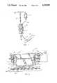
- FIG. 1is a front elevational view of a linear peristaltic pump incorporating the present invention shown in its working environment;
- FIG. 2is a side elevational view of the pumping mechanism of the present invention
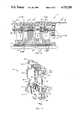
- FIG. 3is a side cross-sectional view along the centerline of the pumping mechanism of the present invention which corresponds to the view seen in FIG. 2;
- FIG. 4is an exploded perspective view of the pumping mechanism with portions cut away for clarity
- FIG. 5is a cross-sectional view of the pumping mechanism as seen along the line 5--5 in FIGS. 3 and 4;
- FIG. 6is cross-sectional view of the pumping mechanism as seen in FIG. 5 when the mechanism is compensating for an excessively thick walled tube;
- FIG. 7is a cross-sectional view of the pumping mechanism as seen along the line 7--7 in FIGS. 3 and 4.
- FIG. 1a set up of the present invention is shown in its intended environment.
- a linear peristaltic pump generally designated 10is shown mounted onto an IV pole 12.
- a fluid source 14is hung from IV pole 12 in a manner well known in the art.
- IV tube 16is connected into fluid communication with the fluid source 14 and operatively engaged with the pumping mechanism 18 of linear peristaltic pump 10. It is further shown in FIG. 1 that IV tube 16 extends from linear peristaltic pump 10 and is attached to patient 20.
- a linear peristaltic pump 10operatively engaged with an IV tube 16 to pump fluid from a fluid source 14 through the IV tube 16 to a patient 20.
- Pumping mechanism 18 of linear peristaltic pump 10is shown by itself and separated from linear peristaltic pump 10 in FIG. 2.
- pumping mechanism 18includes a casing 22, a housing 24, and a drive motor 26, all of which are placed in operative association with a platen 28.
- drive motor 26is operatively associated with casing 22 for moving peristaltic fingers 30 against IV tube 16 which is supported by platen 28.
- drive motor 26is attached to a bracket 32. As shown, this attachment is accomplished through the use of screws, but it will be appreciated by those skilled in the art that this attachment can be accomplished by any number of ways so long as the attachment establishes a fixed relationship between the drive motor 26 and bracket 32.
- Drive motor 26is operatively connected with a drive shaft 34 to cause rotation of drive shaft 34.
- a sleeve 36connects drive shaft 34 with cam shaft 38 so that the rotational motion of drive shaft 34 is transferred through sleeve 36 to cam shaft 38.
- Casing 22includes a bearing 40 and a bearing 42 which support cam shaft 38 for rotation relative to casing 22 and bracket 32 is fixedly attached to casing 22 in a manner which holds drive motor 26, cam shaft 38 and casing 22 in the relationship shown in FIG. 3.
- cam shaft 38remains in the same position with respect to casing 22 and that the rotation of cam shaft 38 about its longitudinal axis can be accomplished without changing this relationship.
- cams 44are arranged lengthwise along cam shaft 38 in a helical relationship. This arrangement of the cams 44 along cam shaft 38, when operatively associated with peristaltic fingers 30, cause a sequential reciprocal motion of the peristaltic fingers 30 that results in a peristaltic action of the fingers 30 against IV tube 16.
- FIG. 3Also shown in FIG. 3 is a membrane 46 which separates the peristaltic fingers 30 from the IV tube 16. Incorporation of membrane 46 serves as a barrier to prevent the unwanted entry of fluids from the IV tube 16 or fluid source 14 into the internal working elements of pumping mechanism 18.
- pumping mechanism 18 of the present inventionis shown incorporating stationary members 48 and a pressure sensor 50. The inclusion of these elements into pumping mechanism 18 are informational to show that the present invention is compatible with the dual mode infusion devices set forth in U.S. Pat. No. 4,617,014 and U.S. patent application Ser. No. 844,414 both of which are assigned to the same assignee as the present invention.
- housing 24is essentially a retangular shaped structure having an open top and an open bottom.
- the open bottom of housing 24provides for the extension of peristaltic fingers 30 therethrough and the consequent operative engagement of peristaltic fingers 30 with IV tube 16.
- the interior side walls 51 of housing 24are formed with a series of grooves 52 which are arranged inside by side relationship and separated by guides 54. The grooves 52 are established for receiving the peristaltic fingers 30 therein and guides 54 are intended to maintain peristaltic fingers 30 within grooves 54 for linear reciprocal action therein. The exact purpose of this will become clear as the discussion of the present invention proceeds.
- FIG. 4shows a hinge tab 78 and hinge pin 80 which can be attached to a hinge ear (not shown) on casing 22 in a manner similarly to that discussed for the attachment of hinge ear 56 with hinge tab 58. It will be understood by a person of ordinary skill in the art, that the hinge mechanism as shown for the present invention in FIG.
- FIG. 4To further show the cooperation of casing 22 in its relationship with housing 24 reference is still made to FIG. 4. There can be seen that in addition to the hinged relationship between casing 22 and housing 24 previously discussed, a spring 66 urges casing 22 toward housing 24 in a predictable manner. To do this, spring 66 is attached to housing 24 at an attachment point 68 and further attached to casing 22 at an attachment point 70. It is understood that the attachment of spring 66 between housing 24 and casing 22 can be accomplished by any manner well known in the art and, that spring 66 is only illustrative of the various flexible structures which could accomplish the same purpose for the present invention.
- casing 22is hingedly attached to housing 24 for rotation about a transverse axis which is defined and established by the hinged connections between casing 22 and housing 24 at hinge tabs 58 and 78. Also, recognize that the rotation of casing 22 relative to housing 24 about the transverse action of the hinge is constrained by the attachment of springs 76 and 66 bring casing 22 into contact with housing 24 in a manner that maintains the positioning of peristaltic fingers 30 within the respective grooves 52 of housing 24.
- peristaltic finger 30is positioned within housing 24 for reciprocal movement along the grooves 52 established by guides 54.
- the body 84 of peristaltic finger 30is formed with a resilient arm 82 that rests within the groove 52 to stabilize the lateral movement of peristaltic finger 30 within housing 24 without creating an interference between peristaltic finger 30 and housing 24.
- peristaltic finger 30is formed with an extender 86 to establish a recess 88 within which a cam 44 may be received. With this engagement, finger 30 moves linearly and reciprocally within housing 24 dependent upon the urging of cam 44 against extender 86 and body 84 of peristaltic finger 30.
- casing 22is hingedly mounted to the housing 24 for rotation about a hinge pin 60.
- hinge pin 60establishes the transverse axis for the hinged connection between casing 22 and housing 24.
- spring 66resists rotation of casing 22 about housing 24 in the direction indicated by arrow 90.
- peristaltic finger 30The motion of peristaltic finger 30 with respect to housing 24 is accomplished in either or both of two ways.
- the second manner in which peristaltic fingers 30 can be moved relative to housing 24is in response to the movement of casing 22 with respect to housing 24.
- cam shaft 38is mounted onto casing 22.
- any force which causes a displacement of cam shaft 38will also manifest itself as a movement of casing 22. Since casing 22 is constrained to rotate about the axis 98 established by hinge 60, this movement will be opposed by the action of springs 66 and 76.
- housing 24is established in fixed spatial relationship with respect to platen 28.
- the distance 96 between edge 100 of peristaltic finger 30 and platen 28will be, in part, determined by the characteristics of IV tube 16.
- sufficient forceneeds to be exerted by the peristaltic finger 30 against IV tube 16 to cause a periodic occlusion.
- it is necessary to constrain or limit this forceso that the adverse effects of an excessive force against IV tube 16 are eliminated.
- FIG. 5it can be seen that any relief from the action of peristaltic finger 30 against IV tube 16 will be manifested through peristaltic finger 30 to cam 44 on cam shaft 38. Recall that cam shaft 38 is mounted for rotation on casing 22.
- FIG. 6shows an IV tube 16' having thicker walls than IV tube 16 in FIG. 5. This will correspondingly cause a change in the distance 96 to 96'. As will be appreciated by the skilled aretsan, this dimensional change manifests itself as a force through peristaltic finger 30 against cam shaft 38. This, in turn, causes cam shaft 38 and casing 22 to rotate about hinge axis 98. During such a rotation, it will be appreciated that the relationship of cam shaft 38 with respect to casing 22 remains unchanged. Thus, pump 10 will operate equally well regardless whether cam shaft 38 and casing 22 are oriented as shown in FIG. 5 or as shown in FIG. 6. Consequently, the actual pumping operation of the linear peristaltic pump 10 of the present invention is accomplished independently of the wall thickness of tube 16.
- IV tube 16is positioned between platen 28 and pumping mechanism 18.
- Cam shaft 38is mounted on casing 22 and drive motor 26 is operatively connected to cam shaft 38 to cause its rotation.
- the consequent action of cams 44 on cam shaft 38causes a linear reciprocal movement of the peristaltic fingers 30 within grooves 52 of housing 24. This movement manifests itself as a moving zone of occlusion against IV tube 16.
- peristaltic fingers 30The forces created by peristaltic fingers 30 against IV tube 16 are limited by the interaction of casing 22 with housing 24. Specifically, and regardless of the dimensions of IV tube 16 being used in association with linear peristaltic pump 10, the peristaltic fingers 30 are able to move into contact with IV tube 16 only to the point that any further force exerted against a peristaltic finger 30 will cause a movement between casing 22 and housing 24.
- any excessive backforce created on peristaltic fingers 30 by variations in the dimensions of IV tube 16will be exerted against cam shaft 38 to rotate casing 22 about hinge axis 98 relative to housing 24. Resistance to this rotational motion of casing 22 about hinge axis 98 is caused by the action of springs 66 and 76 and their connections between casing 22 and 24.
- the peristaltic action of pumping mechanism 18 against IV tube 16can be accomplished independently of dimensional variables introduced by IV tube 16 and with equal efficiency for various IV tubes 16.
- cam action compensatoras herein shown and disclosed in detail is fully capable of obtaining the objects and providing the advantages hereinbefore stated, it is to be understood that it is merely illustrative of the presently preferred embodiment of the invention and that no limitations are intended to the details of construction or design herein shown other than as defined in the appended claims.
Landscapes
- Engineering & Computer Science (AREA)
- Health & Medical Sciences (AREA)
- Mechanical Engineering (AREA)
- General Engineering & Computer Science (AREA)
- Biomedical Technology (AREA)
- Anesthesiology (AREA)
- Vascular Medicine (AREA)
- Heart & Thoracic Surgery (AREA)
- Hematology (AREA)
- Life Sciences & Earth Sciences (AREA)
- Animal Behavior & Ethology (AREA)
- General Health & Medical Sciences (AREA)
- Public Health (AREA)
- Veterinary Medicine (AREA)
- Reciprocating Pumps (AREA)
Abstract
Description
Claims (20)
Priority Applications (2)
| Application Number | Priority Date | Filing Date | Title |
|---|---|---|---|
| US07/009,265US4725205A (en) | 1987-01-30 | 1987-01-30 | Peristaltic pump with cam action compensator |
| US07/017,846US4728265A (en) | 1987-01-30 | 1987-02-24 | Peristaltic pump with cam action compensator |
Applications Claiming Priority (1)
| Application Number | Priority Date | Filing Date | Title |
|---|---|---|---|
| US07/009,265US4725205A (en) | 1987-01-30 | 1987-01-30 | Peristaltic pump with cam action compensator |
Related Child Applications (1)
| Application Number | Title | Priority Date | Filing Date |
|---|---|---|---|
| US07/017,846Continuation-In-PartUS4728265A (en) | 1987-01-30 | 1987-02-24 | Peristaltic pump with cam action compensator |
Publications (1)
| Publication Number | Publication Date |
|---|---|
| US4725205Atrue US4725205A (en) | 1988-02-16 |
Family
ID=21736597
Family Applications (1)
| Application Number | Title | Priority Date | Filing Date |
|---|---|---|---|
| US07/009,265Expired - LifetimeUS4725205A (en) | 1987-01-30 | 1987-01-30 | Peristaltic pump with cam action compensator |
Country Status (1)
| Country | Link |
|---|---|
| US (1) | US4725205A (en) |
Cited By (51)
| Publication number | Priority date | Publication date | Assignee | Title |
|---|---|---|---|---|
| US4909710A (en)* | 1989-10-23 | 1990-03-20 | Fisher Scientific Company | Linear peristaltic pump |
| US4950245A (en)* | 1988-07-08 | 1990-08-21 | I-Flow Corporation | Multiple fluid cartridge and pump |
| US4988069A (en)* | 1989-11-27 | 1991-01-29 | Baxter International Inc. | Stepping motor mounting |
| US5018945A (en)* | 1989-12-14 | 1991-05-28 | Baxter International Inc. | Accurate peristaltic pump |
| US5088904A (en)* | 1989-07-24 | 1992-02-18 | Terumo Kabushiki Kaisha | Transfusion pump |
| US5088522A (en)* | 1989-03-23 | 1992-02-18 | B. Braun Melsungen Ag | Pump hose for a peristaltic pump |
| US5090877A (en)* | 1990-08-23 | 1992-02-25 | Baxter International Inc. | Misloaded iv tube detector for an iv pump |
| US5120096A (en)* | 1990-08-23 | 1992-06-09 | Baxter International Inc. | Misloaded IV tube detector for an IV pump |
| US5131816A (en)* | 1988-07-08 | 1992-07-21 | I-Flow Corporation | Cartridge fed programmable ambulatory infusion pumps powered by DC electric motors |
| US5211548A (en)* | 1989-07-31 | 1993-05-18 | Terumo Kabushiki Kaisha | Peristaltic pump having a motor overload protector |
| US5217355A (en)* | 1991-08-05 | 1993-06-08 | Imed Corporation | Two-cycle peristaltic pump with occlusion detector |
| US5395320A (en)* | 1992-06-09 | 1995-03-07 | Sabratek Corporation | Programmable infusion pump with interchangeable tubing |
| US5447417A (en)* | 1993-08-31 | 1995-09-05 | Valleylab Inc. | Self-adjusting pump head and safety manifold cartridge for a peristaltic pump |
| WO1995024229A3 (en)* | 1994-03-09 | 1995-10-26 | Baxter Int | Ambulatory infusion pump |
| US5558507A (en)* | 1992-04-29 | 1996-09-24 | Mastermark Corporation | Hose pump using angularly staggered eccentric disks with projecting stub shafts |
| US5609575A (en)* | 1994-04-11 | 1997-03-11 | Graseby Medical Limited | Infusion pump and method with dose-rate calculation |
| US5620312A (en)* | 1995-03-06 | 1997-04-15 | Sabratek Corporation | Infusion pump with dual-latching mechanism |
| US5628619A (en)* | 1995-03-06 | 1997-05-13 | Sabratek Corporation | Infusion pump having power-saving modes |
| US5637093A (en)* | 1995-03-06 | 1997-06-10 | Sabratek Corporation | Infusion pump with selective backlight |
| US5795327A (en)* | 1995-03-06 | 1998-08-18 | Sabratek Corporation | Infusion pump with historical data recording |
| US5842841A (en)* | 1996-04-10 | 1998-12-01 | Baxter International, Inc. | Volumetric infusion pump with transverse tube loader |
| US5904668A (en)* | 1995-03-06 | 1999-05-18 | Sabratek Corporation | Cassette for an infusion pump |
| US6468242B1 (en) | 1998-03-06 | 2002-10-22 | Baxter International Inc. | Medical apparatus with patient data recording |
| US20030233069A1 (en)* | 2002-06-14 | 2003-12-18 | John Gillespie | Infusion pump |
| US20060002805A1 (en)* | 2004-06-30 | 2006-01-05 | Millipore Corporation | Peristaltic pump comprising members for locating a tube |
| US6997905B2 (en) | 2002-06-14 | 2006-02-14 | Baxter International Inc. | Dual orientation display for a medical device |
| US20060228240A1 (en)* | 2005-03-30 | 2006-10-12 | Lancer Partnership, Ltd. | Method and apparatus for a linear peristaltic pump |
| US20060228232A1 (en)* | 2005-03-31 | 2006-10-12 | Arimitsu Of North America, Inc. | Pump and motor assembly |
| US20100036322A1 (en)* | 2006-11-13 | 2010-02-11 | Q-Core Medical Ltd. | Anti-free flow mechanism |
| US20100106082A1 (en)* | 2008-10-24 | 2010-04-29 | Baxter International Inc. | In situ tubing measurements for infusion pumps |
| US20110158823A1 (en)* | 2009-12-31 | 2011-06-30 | Baxter International Inc. | Shuttle pump with controlled geometry |
| US8137083B2 (en) | 2009-03-11 | 2012-03-20 | Baxter International Inc. | Infusion pump actuators, system and method for controlling medical fluid flowrate |
| CN103104444A (en)* | 2013-01-29 | 2013-05-15 | 深圳玉升医疗科技有限公司 | Peristaltic device |
| US8567235B2 (en) | 2010-06-29 | 2013-10-29 | Baxter International Inc. | Tube measurement technique using linear actuator and pressure sensor |
| US9056160B2 (en) | 2006-11-13 | 2015-06-16 | Q-Core Medical Ltd | Magnetically balanced finger-type peristaltic pump |
| US9404490B2 (en) | 2004-11-24 | 2016-08-02 | Q-Core Medical Ltd. | Finger-type peristaltic pump |
| US9457158B2 (en) | 2010-04-12 | 2016-10-04 | Q-Core Medical Ltd. | Air trap for intravenous pump |
| US9657902B2 (en) | 2004-11-24 | 2017-05-23 | Q-Core Medical Ltd. | Peristaltic infusion pump with locking mechanism |
| US9674811B2 (en) | 2011-01-16 | 2017-06-06 | Q-Core Medical Ltd. | Methods, apparatus and systems for medical device communication, control and localization |
| US9675756B2 (en) | 2011-12-21 | 2017-06-13 | Deka Products Limited Partnership | Apparatus for infusing fluid |
| US9677555B2 (en) | 2011-12-21 | 2017-06-13 | Deka Products Limited Partnership | System, method, and apparatus for infusing fluid |
| US9726167B2 (en) | 2011-06-27 | 2017-08-08 | Q-Core Medical Ltd. | Methods, circuits, devices, apparatuses, encasements and systems for identifying if a medical infusion system is decalibrated |
| US9855110B2 (en) | 2013-02-05 | 2018-01-02 | Q-Core Medical Ltd. | Methods, apparatus and systems for operating a medical device including an accelerometer |
| US20180221570A1 (en)* | 2014-08-27 | 2018-08-09 | Vidacare LLC | Pumping apparatuses and methods for fluid infusion |
| US10113543B2 (en) | 2006-11-13 | 2018-10-30 | Q-Core Medical Ltd. | Finger type peristaltic pump comprising a ribbed anvil |
| US10265463B2 (en) | 2014-09-18 | 2019-04-23 | Deka Products Limited Partnership | Apparatus and method for infusing fluid through a tube by appropriately heating the tube |
| WO2020219574A1 (en)* | 2019-04-23 | 2020-10-29 | Carefusion 303, Inc. | Silent pumping mechanism for infusion pump |
| US11295846B2 (en) | 2011-12-21 | 2022-04-05 | Deka Products Limited Partnership | System, method, and apparatus for infusing fluid |
| US11679189B2 (en) | 2019-11-18 | 2023-06-20 | Eitan Medical Ltd. | Fast test for medical pump |
| US11707615B2 (en) | 2018-08-16 | 2023-07-25 | Deka Products Limited Partnership | Medical pump |
| US12098738B2 (en) | 2011-12-21 | 2024-09-24 | Deka Products Limited Partnership | System, method, and apparatus for clamping |
Citations (16)
| Publication number | Priority date | Publication date | Assignee | Title |
|---|---|---|---|---|
| DE546884C (en)* | 1930-07-01 | 1932-03-19 | Heinrich Koppers Akt Ges | Valveless pump with hose-like hollow rubber body and pressure members that come into effect on these |
| US3137242A (en)* | 1962-01-22 | 1964-06-16 | Hahn George William | Infusion pump |
| US3140666A (en)* | 1962-06-11 | 1964-07-14 | American Instr Co Inc | Peristaltic pump |
| US3582234A (en)* | 1969-07-14 | 1971-06-01 | Technicon Corp | Method and apparatus for the calibration of tubing to provide for a desired flow rate therethrough |
| US3658445A (en)* | 1969-06-12 | 1972-04-25 | Prockter T Pulman | Pumps |
| US3737251A (en)* | 1971-02-08 | 1973-06-05 | Alphamedics Mfg Cop | Peristaltic pump |
| US4095923A (en)* | 1975-09-25 | 1978-06-20 | Baxter Travenol Laboratories, Inc. | Peristaltic pump with accommodating rollers |
| US4155362A (en)* | 1976-01-26 | 1979-05-22 | Baxter Travenol Laboratories, Inc. | Method and apparatus for metered infusion of fluids |
| US4233001A (en)* | 1979-02-28 | 1980-11-11 | Peerless Electronics Research Corporation | Peristaltic pump |
| US4278085A (en)* | 1979-12-13 | 1981-07-14 | Baxter Travenol Laboratories, Inc. | Method and apparatus for metered infusion of fluids |
| US4373525A (en)* | 1980-02-12 | 1983-02-15 | Terumo Corporation | Method and apparatus for detecting occlusion in fluid-infusion tube of peristaltic type fluid-infusion pump |
| US4479797A (en)* | 1981-07-04 | 1984-10-30 | Terumo Corporation | Medication infusion device |
| US4482347A (en)* | 1982-08-12 | 1984-11-13 | American Hospital Supply Corporation | Peristaltic fluid-pumping apparatus |
| JPS60230582A (en)* | 1984-04-27 | 1985-11-16 | Hitachi Ltd | Roller type squeeze pump |
| US4559038A (en)* | 1984-10-19 | 1985-12-17 | Deltec Systems, Inc. | Drug delivery system |
| US4653987A (en)* | 1984-07-06 | 1987-03-31 | Tsuyoshi Tsuji | Finger peristaltic infusion pump |
- 1987
- 1987-01-30USUS07/009,265patent/US4725205A/ennot_activeExpired - Lifetime
Patent Citations (16)
| Publication number | Priority date | Publication date | Assignee | Title |
|---|---|---|---|---|
| DE546884C (en)* | 1930-07-01 | 1932-03-19 | Heinrich Koppers Akt Ges | Valveless pump with hose-like hollow rubber body and pressure members that come into effect on these |
| US3137242A (en)* | 1962-01-22 | 1964-06-16 | Hahn George William | Infusion pump |
| US3140666A (en)* | 1962-06-11 | 1964-07-14 | American Instr Co Inc | Peristaltic pump |
| US3658445A (en)* | 1969-06-12 | 1972-04-25 | Prockter T Pulman | Pumps |
| US3582234A (en)* | 1969-07-14 | 1971-06-01 | Technicon Corp | Method and apparatus for the calibration of tubing to provide for a desired flow rate therethrough |
| US3737251A (en)* | 1971-02-08 | 1973-06-05 | Alphamedics Mfg Cop | Peristaltic pump |
| US4095923A (en)* | 1975-09-25 | 1978-06-20 | Baxter Travenol Laboratories, Inc. | Peristaltic pump with accommodating rollers |
| US4155362A (en)* | 1976-01-26 | 1979-05-22 | Baxter Travenol Laboratories, Inc. | Method and apparatus for metered infusion of fluids |
| US4233001A (en)* | 1979-02-28 | 1980-11-11 | Peerless Electronics Research Corporation | Peristaltic pump |
| US4278085A (en)* | 1979-12-13 | 1981-07-14 | Baxter Travenol Laboratories, Inc. | Method and apparatus for metered infusion of fluids |
| US4373525A (en)* | 1980-02-12 | 1983-02-15 | Terumo Corporation | Method and apparatus for detecting occlusion in fluid-infusion tube of peristaltic type fluid-infusion pump |
| US4479797A (en)* | 1981-07-04 | 1984-10-30 | Terumo Corporation | Medication infusion device |
| US4482347A (en)* | 1982-08-12 | 1984-11-13 | American Hospital Supply Corporation | Peristaltic fluid-pumping apparatus |
| JPS60230582A (en)* | 1984-04-27 | 1985-11-16 | Hitachi Ltd | Roller type squeeze pump |
| US4653987A (en)* | 1984-07-06 | 1987-03-31 | Tsuyoshi Tsuji | Finger peristaltic infusion pump |
| US4559038A (en)* | 1984-10-19 | 1985-12-17 | Deltec Systems, Inc. | Drug delivery system |
Cited By (97)
| Publication number | Priority date | Publication date | Assignee | Title |
|---|---|---|---|---|
| US4950245A (en)* | 1988-07-08 | 1990-08-21 | I-Flow Corporation | Multiple fluid cartridge and pump |
| US5131816A (en)* | 1988-07-08 | 1992-07-21 | I-Flow Corporation | Cartridge fed programmable ambulatory infusion pumps powered by DC electric motors |
| US5088522A (en)* | 1989-03-23 | 1992-02-18 | B. Braun Melsungen Ag | Pump hose for a peristaltic pump |
| US5088904A (en)* | 1989-07-24 | 1992-02-18 | Terumo Kabushiki Kaisha | Transfusion pump |
| US5152680A (en)* | 1989-07-24 | 1992-10-06 | Terumo Kabushiki Kaisha | Transfusion pump |
| US5211548A (en)* | 1989-07-31 | 1993-05-18 | Terumo Kabushiki Kaisha | Peristaltic pump having a motor overload protector |
| US5290158A (en)* | 1989-07-31 | 1994-03-01 | Terumo Kabushiki Kaisha | Peristaltic pump |
| US4909710A (en)* | 1989-10-23 | 1990-03-20 | Fisher Scientific Company | Linear peristaltic pump |
| US4988069A (en)* | 1989-11-27 | 1991-01-29 | Baxter International Inc. | Stepping motor mounting |
| US5018945A (en)* | 1989-12-14 | 1991-05-28 | Baxter International Inc. | Accurate peristaltic pump |
| US5090877A (en)* | 1990-08-23 | 1992-02-25 | Baxter International Inc. | Misloaded iv tube detector for an iv pump |
| WO1992003658A1 (en)* | 1990-08-23 | 1992-03-05 | Baxter International Inc. | Misloaded iv tube detector for an iv pump |
| US5120096A (en)* | 1990-08-23 | 1992-06-09 | Baxter International Inc. | Misloaded IV tube detector for an IV pump |
| US5217355A (en)* | 1991-08-05 | 1993-06-08 | Imed Corporation | Two-cycle peristaltic pump with occlusion detector |
| US5558507A (en)* | 1992-04-29 | 1996-09-24 | Mastermark Corporation | Hose pump using angularly staggered eccentric disks with projecting stub shafts |
| US5395320A (en)* | 1992-06-09 | 1995-03-07 | Sabratek Corporation | Programmable infusion pump with interchangeable tubing |
| US5447417A (en)* | 1993-08-31 | 1995-09-05 | Valleylab Inc. | Self-adjusting pump head and safety manifold cartridge for a peristaltic pump |
| WO1995024229A3 (en)* | 1994-03-09 | 1995-10-26 | Baxter Int | Ambulatory infusion pump |
| US5482438A (en)* | 1994-03-09 | 1996-01-09 | Anderson; Robert L. | Magnetic detent and position detector for fluid pump motor |
| US5609575A (en)* | 1994-04-11 | 1997-03-11 | Graseby Medical Limited | Infusion pump and method with dose-rate calculation |
| US5620312A (en)* | 1995-03-06 | 1997-04-15 | Sabratek Corporation | Infusion pump with dual-latching mechanism |
| US5628619A (en)* | 1995-03-06 | 1997-05-13 | Sabratek Corporation | Infusion pump having power-saving modes |
| US5637093A (en)* | 1995-03-06 | 1997-06-10 | Sabratek Corporation | Infusion pump with selective backlight |
| US5766155A (en)* | 1995-03-06 | 1998-06-16 | Sabratek Corporation | Infusion pump with selective backlight |
| US5791880A (en)* | 1995-03-06 | 1998-08-11 | Sabratek Corporation | Infusion pump having power-saving modes |
| US5795327A (en)* | 1995-03-06 | 1998-08-18 | Sabratek Corporation | Infusion pump with historical data recording |
| US5993420A (en)* | 1995-03-06 | 1999-11-30 | Sabratek Corporation | Cassette for an infusion pump |
| US5904668A (en)* | 1995-03-06 | 1999-05-18 | Sabratek Corporation | Cassette for an infusion pump |
| SG82622A1 (en)* | 1996-04-10 | 2001-08-21 | Baxter Int | Volumetric infusion pump |
| US6195887B1 (en)* | 1996-04-10 | 2001-03-06 | Baxter International Inc | Volumetric infusion pump |
| US5842841A (en)* | 1996-04-10 | 1998-12-01 | Baxter International, Inc. | Volumetric infusion pump with transverse tube loader |
| US6468242B1 (en) | 1998-03-06 | 2002-10-22 | Baxter International Inc. | Medical apparatus with patient data recording |
| US9514518B2 (en) | 2002-06-14 | 2016-12-06 | Baxter International Inc. | Infusion pump including syringe plunger position sensor |
| US6997905B2 (en) | 2002-06-14 | 2006-02-14 | Baxter International Inc. | Dual orientation display for a medical device |
| US7018361B2 (en) | 2002-06-14 | 2006-03-28 | Baxter International Inc. | Infusion pump |
| US20060184123A1 (en)* | 2002-06-14 | 2006-08-17 | Gillespie John Jr | Infusion pump |
| US8888738B2 (en) | 2002-06-14 | 2014-11-18 | Baxter International Inc. | Infusion pump with multiple orientation display |
| US8696632B2 (en) | 2002-06-14 | 2014-04-15 | Baxter International Inc. | Infusion pump with battery operation capability |
| US7608060B2 (en) | 2002-06-14 | 2009-10-27 | Baxter International Inc. | Infusion pump |
| US10092690B2 (en) | 2002-06-14 | 2018-10-09 | Baxter International Inc. | Infusion pump including syringe sensing |
| US9937289B2 (en) | 2002-06-14 | 2018-04-10 | Baxter International Inc. | Method of operating an infusion pump with a multiple orientation display |
| US20030233069A1 (en)* | 2002-06-14 | 2003-12-18 | John Gillespie | Infusion pump |
| US20100256561A1 (en)* | 2002-06-14 | 2010-10-07 | Baxter International Inc. | Infusion pump with battery operation capability |
| US20060002805A1 (en)* | 2004-06-30 | 2006-01-05 | Millipore Corporation | Peristaltic pump comprising members for locating a tube |
| US7467932B2 (en)* | 2004-06-30 | 2008-12-23 | Millipore Corporation | Peristaltic pump comprising members for locating a tube |
| US9657902B2 (en) | 2004-11-24 | 2017-05-23 | Q-Core Medical Ltd. | Peristaltic infusion pump with locking mechanism |
| US9404490B2 (en) | 2004-11-24 | 2016-08-02 | Q-Core Medical Ltd. | Finger-type peristaltic pump |
| US10184615B2 (en) | 2004-11-24 | 2019-01-22 | Q-Core Medical Ltd. | Peristaltic infusion pump with locking mechanism |
| US20060228240A1 (en)* | 2005-03-30 | 2006-10-12 | Lancer Partnership, Ltd. | Method and apparatus for a linear peristaltic pump |
| US7614855B2 (en)* | 2005-03-31 | 2009-11-10 | Arimitsu Of North America, Inc. | Pump and motor assembly |
| US20060228232A1 (en)* | 2005-03-31 | 2006-10-12 | Arimitsu Of North America, Inc. | Pump and motor assembly |
| US9581152B2 (en) | 2006-11-13 | 2017-02-28 | Q-Core Medical Ltd. | Magnetically balanced finger-type peristaltic pump |
| US10113543B2 (en) | 2006-11-13 | 2018-10-30 | Q-Core Medical Ltd. | Finger type peristaltic pump comprising a ribbed anvil |
| US20100036322A1 (en)* | 2006-11-13 | 2010-02-11 | Q-Core Medical Ltd. | Anti-free flow mechanism |
| US9056160B2 (en) | 2006-11-13 | 2015-06-16 | Q-Core Medical Ltd | Magnetically balanced finger-type peristaltic pump |
| US9333290B2 (en)* | 2006-11-13 | 2016-05-10 | Q-Core Medical Ltd. | Anti-free flow mechanism |
| US20100106082A1 (en)* | 2008-10-24 | 2010-04-29 | Baxter International Inc. | In situ tubing measurements for infusion pumps |
| US8496613B2 (en) | 2008-10-24 | 2013-07-30 | Baxter International Inc. | In situ tubing measurements for infusion pumps |
| US8105269B2 (en) | 2008-10-24 | 2012-01-31 | Baxter International Inc. | In situ tubing measurements for infusion pumps |
| US8137083B2 (en) | 2009-03-11 | 2012-03-20 | Baxter International Inc. | Infusion pump actuators, system and method for controlling medical fluid flowrate |
| US8382447B2 (en) | 2009-12-31 | 2013-02-26 | Baxter International, Inc. | Shuttle pump with controlled geometry |
| US20110158823A1 (en)* | 2009-12-31 | 2011-06-30 | Baxter International Inc. | Shuttle pump with controlled geometry |
| US9457158B2 (en) | 2010-04-12 | 2016-10-04 | Q-Core Medical Ltd. | Air trap for intravenous pump |
| US8567235B2 (en) | 2010-06-29 | 2013-10-29 | Baxter International Inc. | Tube measurement technique using linear actuator and pressure sensor |
| US9674811B2 (en) | 2011-01-16 | 2017-06-06 | Q-Core Medical Ltd. | Methods, apparatus and systems for medical device communication, control and localization |
| US9726167B2 (en) | 2011-06-27 | 2017-08-08 | Q-Core Medical Ltd. | Methods, circuits, devices, apparatuses, encasements and systems for identifying if a medical infusion system is decalibrated |
| US11024409B2 (en) | 2011-12-21 | 2021-06-01 | Deka Products Limited Partnership | Peristaltic pump |
| US11295846B2 (en) | 2011-12-21 | 2022-04-05 | Deka Products Limited Partnership | System, method, and apparatus for infusing fluid |
| US12288604B2 (en) | 2011-12-21 | 2025-04-29 | Deka Products Limited Partnership | Peristaltic pump |
| US12098738B2 (en) | 2011-12-21 | 2024-09-24 | Deka Products Limited Partnership | System, method, and apparatus for clamping |
| US9677555B2 (en) | 2011-12-21 | 2017-06-13 | Deka Products Limited Partnership | System, method, and apparatus for infusing fluid |
| US10202970B2 (en) | 2011-12-21 | 2019-02-12 | Deka Products Limited Partnership | System, method, and apparatus for infusing fluid |
| US10202971B2 (en) | 2011-12-21 | 2019-02-12 | Deka Products Limited Partnership | Peristaltic pump |
| US12020798B2 (en) | 2011-12-21 | 2024-06-25 | Deka Products Limited Partnership | Peristaltic pump and related method |
| US10288057B2 (en) | 2011-12-21 | 2019-05-14 | Deka Products Limited Partnership | Peristaltic pump |
| US10316834B2 (en) | 2011-12-21 | 2019-06-11 | Deka Products Limited Partnership | Peristaltic pump |
| US10753353B2 (en) | 2011-12-21 | 2020-08-25 | Deka Products Limited Partnership | Peristaltic pump |
| US12002561B2 (en) | 2011-12-21 | 2024-06-04 | DEKA Research & Development Corp | System, method, and apparatus for infusing fluid |
| US10857293B2 (en) | 2011-12-21 | 2020-12-08 | Deka Products Limited Partnership | Apparatus for infusing fluid |
| US9675756B2 (en) | 2011-12-21 | 2017-06-13 | Deka Products Limited Partnership | Apparatus for infusing fluid |
| US11779703B2 (en) | 2011-12-21 | 2023-10-10 | Deka Products Limited Partnership | Apparatus for infusing fluid |
| US11756662B2 (en) | 2011-12-21 | 2023-09-12 | Deka Products Limited Partnership | Peristaltic pump |
| US11348674B2 (en) | 2011-12-21 | 2022-05-31 | Deka Products Limited Partnership | Peristaltic pump |
| US11373747B2 (en) | 2011-12-21 | 2022-06-28 | Deka Products Limited Partnership | Peristaltic pump |
| US11511038B2 (en) | 2011-12-21 | 2022-11-29 | Deka Products Limited Partnership | Apparatus for infusing fluid |
| US11705233B2 (en) | 2011-12-21 | 2023-07-18 | Deka Products Limited Partnership | Peristaltic pump |
| CN103104444A (en)* | 2013-01-29 | 2013-05-15 | 深圳玉升医疗科技有限公司 | Peristaltic device |
| US9855110B2 (en) | 2013-02-05 | 2018-01-02 | Q-Core Medical Ltd. | Methods, apparatus and systems for operating a medical device including an accelerometer |
| US20180221570A1 (en)* | 2014-08-27 | 2018-08-09 | Vidacare LLC | Pumping apparatuses and methods for fluid infusion |
| US11672903B2 (en) | 2014-09-18 | 2023-06-13 | Deka Products Limited Partnership | Apparatus and method for infusing fluid through a tube by appropriately heating the tube |
| US10265463B2 (en) | 2014-09-18 | 2019-04-23 | Deka Products Limited Partnership | Apparatus and method for infusing fluid through a tube by appropriately heating the tube |
| US11707615B2 (en) | 2018-08-16 | 2023-07-25 | Deka Products Limited Partnership | Medical pump |
| US12251532B2 (en) | 2018-08-16 | 2025-03-18 | Deka Products Limited Partnership | Medical pump |
| CN114007668A (en)* | 2019-04-23 | 2022-02-01 | 康尔福盛303公司 | Silent pumping mechanism for infusion pumps |
| CN114007668B (en)* | 2019-04-23 | 2024-04-12 | 康尔福盛303公司 | Quiet pumping mechanism for infusion pumps |
| WO2020219574A1 (en)* | 2019-04-23 | 2020-10-29 | Carefusion 303, Inc. | Silent pumping mechanism for infusion pump |
| US11679189B2 (en) | 2019-11-18 | 2023-06-20 | Eitan Medical Ltd. | Fast test for medical pump |
Similar Documents
| Publication | Publication Date | Title |
|---|---|---|
| US4725205A (en) | Peristaltic pump with cam action compensator | |
| US4728265A (en) | Peristaltic pump with cam action compensator | |
| EP0282324B1 (en) | Improved pump pressure sensor | |
| AU622088B2 (en) | Peristaltic pump with mechanism for maintaining linear flow | |
| JP2591732B2 (en) | Linear peristaltic pump | |
| EP0781378B1 (en) | Fluid delivery system with mounting linkage | |
| CA1259871A (en) | Fluid infusion pump driver | |
| US5056992A (en) | IV pump and disposable flow chamber with flow control | |
| US4909710A (en) | Linear peristaltic pump | |
| AU2001238698B2 (en) | Force sensor assembly for an infusion pump | |
| CA1127491A (en) | Medical infusion system | |
| US5322422A (en) | Volumetric pump tube reshaper and method | |
| US5092749A (en) | Fluid pump drive mechanism | |
| AU7194494A (en) | Pump head cartridge | |
| US4755109A (en) | Snap-together peristaltic mechanism | |
| AU2001238698A1 (en) | Force sensor assembly for an infusion pump | |
| US5219279A (en) | Volumetric pump with pump plunger support and method | |
| CN213491141U (en) | Cassette for use with pump for delivering liquid and device for delivering liquid | |
| JPH0423547B2 (en) | ||
| JPH0599154A (en) | Spring energizing valve for positive displacement type pump device | |
| EP0293241B1 (en) | Intravenous pump with disposable chamber | |
| JPS6075786A (en) | Vermicular motion type roller pump and pump rotor | |
| JPH0511873Y2 (en) | ||
| CN117915968A (en) | Infusion sets that keep fluid lines secure |
Legal Events
| Date | Code | Title | Description |
|---|---|---|---|
| AS | Assignment | Owner name:FISHER SCIENTIFIC GROUP INC., 9925 CARROLL CANYON Free format text:ASSIGNMENT OF ASSIGNORS INTEREST.;ASSIGNORS:CANNON, RAYMOND E.;BLOOMQUIST, TED C.;REEL/FRAME:004669/0079 Effective date:19870130 Owner name:FISHER SCIENTIFIC GROUP INC., A CORP. OF DE.,CALIF Free format text:ASSIGNMENT OF ASSIGNORS INTEREST;ASSIGNORS:CANNON, RAYMOND E.;BLOOMQUIST, TED C.;REEL/FRAME:004669/0079 Effective date:19870130 | |
| STCF | Information on status: patent grant | Free format text:PATENTED CASE | |
| AS | Assignment | Owner name:FISCHER SCIENTIFIC COMPANY, A CORP. OF DE Free format text:ASSIGNMENT OF ASSIGNORS INTEREST.;ASSIGNOR:FISCHER SCIENTIFIC GROUP, INC., A CORP. OF DE.;REEL/FRAME:005278/0534 Effective date:19900402 Owner name:GENERAL ELECTRIC CAPITAL CORPORATION, A CORP. OF N Free format text:SECURITY INTEREST;ASSIGNOR:IMED CORPORATION;REEL/FRAME:005278/0541 Effective date:19900402 Owner name:IMED CORPORATION, A CORP. OF DE Free format text:ASSIGNMENT OF ASSIGNORS INTEREST.;ASSIGNOR:FISHER SCIENTIFIC COMPANY, A CORP., OF DE;REEL/FRAME:005278/0559 Effective date:19900402 | |
| FEPP | Fee payment procedure | Free format text:PAYOR NUMBER ASSIGNED (ORIGINAL EVENT CODE: ASPN); ENTITY STATUS OF PATENT OWNER: LARGE ENTITY | |
| FPAY | Fee payment | Year of fee payment:4 | |
| FPAY | Fee payment | Year of fee payment:8 | |
| AS | Assignment | Owner name:IMED CORPORATION, CALIFORNIA Free format text:SECURITY INTEREST;ASSIGNOR:GENERAL ELECTRIC CAPITAL CORPORATION;REEL/FRAME:008454/0006 Effective date:19961126 | |
| AS | Assignment | Owner name:BANKERS TRUST COMPANY, NEW YORK Free format text:SECURITY INTEREST;ASSIGNOR:IVAC HOLDINGS, INC.;REEL/FRAME:008568/0540 Effective date:19961126 | |
| AS | Assignment | Owner name:ALARIS MEDICAL SYSTEMS, INC, CALIFORNIA Free format text:CHANGE OF NAME;ASSIGNOR:IVAC HOLDINGS, INC.;REEL/FRAME:008628/0252 Effective date:19970429 Owner name:IVAC HOLDINGS, INC., CALIFORNIA Free format text:MERGER;ASSIGNOR:IMED CORPORATION;REEL/FRAME:008613/0837 Effective date:19961126 | |
| FPAY | Fee payment | Year of fee payment:12 | |
| AS | Assignment | Owner name:IISBC BANK USA, NEW YORK Free format text:SECURITY INTEREST;ASSIGNOR:ALARIS MEDICAL SYSTEMS, INC.;REEL/FRAME:013403/0338 Effective date:20011016 | |
| AS | Assignment | Owner name:ALARIS MEDICAL SYSTEMS, INC., CALIFORNIA Free format text:CHANGE OF NAME;ASSIGNOR:ALARIS MEDICAL, INC.;REEL/FRAME:014201/0592 Effective date:20030630 Owner name:ALARIS MEDICAL SYSTEMS, INC., CALIFORNIA Free format text:SECURITY AGREEMENT;ASSIGNOR:HSBC BANK USA;REEL/FRAME:014220/0171 Effective date:20030630 Owner name:ALARIS MEDICAL, INC., CALIFORNIA Free format text:MERGER;ASSIGNOR:ALARIS MEDICAL SYSTEMS, INC.;REEL/FRAME:014220/0417 Effective date:20030630 Owner name:CITICORP NORTH AMERICA, INC., NEW YORK Free format text:SECURITY AGREEMENT;ASSIGNOR:ALARIS MEDICAL SYSTEMS, INC.;REEL/FRAME:014220/0315 Effective date:20030630 | |
| AS | Assignment | Owner name:ALARIS MEDICAL SYSTEMS, INC., CALIFORNIA Free format text:RELEASE OF SECURITY AGREEMENT;ASSIGNOR:CITICORP NORTH AMERICA, INC.;REEL/FRAME:015703/0127 Effective date:20040707 | |
| AS | Assignment | Owner name:CARDINAL HEALTH 303, INC., CALIFORNIA Free format text:CHANGE OF NAME;ASSIGNOR:ALARIS MEDICAL SYSTEMS, INC.;REEL/FRAME:016914/0962 Effective date:20041013 |