US4725087A - Spring-loaded hand for an industrial robot - Google Patents
Spring-loaded hand for an industrial robotDownload PDFInfo
- Publication number
- US4725087A US4725087AUS06/839,381US83938186AUS4725087AUS 4725087 AUS4725087 AUS 4725087AUS 83938186 AUS83938186 AUS 83938186AUS 4725087 AUS4725087 AUS 4725087A
- Authority
- US
- United States
- Prior art keywords
- recited
- supporting arms
- hand apparatus
- supporting
- base
- Prior art date
- Legal status (The legal status is an assumption and is not a legal conclusion. Google has not performed a legal analysis and makes no representation as to the accuracy of the status listed.)
- Expired - Fee Related
Links
Images


Classifications
- B—PERFORMING OPERATIONS; TRANSPORTING
- B25—HAND TOOLS; PORTABLE POWER-DRIVEN TOOLS; MANIPULATORS
- B25J—MANIPULATORS; CHAMBERS PROVIDED WITH MANIPULATION DEVICES
- B25J15/00—Gripping heads and other end effectors
- B—PERFORMING OPERATIONS; TRANSPORTING
- B25—HAND TOOLS; PORTABLE POWER-DRIVEN TOOLS; MANIPULATORS
- B25J—MANIPULATORS; CHAMBERS PROVIDED WITH MANIPULATION DEVICES
- B25J17/00—Joints
- B25J17/02—Wrist joints
- B25J17/0208—Compliance devices
- B—PERFORMING OPERATIONS; TRANSPORTING
- B25—HAND TOOLS; PORTABLE POWER-DRIVEN TOOLS; MANIPULATORS
- B25J—MANIPULATORS; CHAMBERS PROVIDED WITH MANIPULATION DEVICES
- B25J19/00—Accessories fitted to manipulators, e.g. for monitoring, for viewing; Safety devices combined with or specially adapted for use in connection with manipulators
- B25J19/0091—Shock absorbers
Definitions
- the present inventiongenerally relates to a hand apparatus of an industrial robot.
- itrelates to an apparatus for effectively causing a floating mechanism including a simple energizing spring to perform any one of a number of gripping functions of double hands.
- FIGS. 1 and 2are diagrams showing the conventional double hands provided with a floating mechanism. Such hands are disclosed, for example, in Japanese Unexamined Utility Model Publication No. 55-66789, and FIG. 1 is a perspective view of such a hand. FIG. 2 is a side view of FIG. 1.
- a double handis composed of a pair of grippers 3 and 4 arranged parallel to each other and displaced along the direction of a central axis, as indicated by a single-dot chain line 2. The two grippers 3 and 4 are used for gripping a workpiece.
- Respective pairs of gripping pawls 5 and 6, provided on the grippers 3 and 4,are arranged to be openable and closable in respective planes that are perpendicular to the central axis 2.
- the pawls 5 and 6are actuated through respective link mechanisms 7 and 8.
- the opening and closing of the gripping pawls 5 and 6is performed by actuators (not shown) provided in the respective base portions of the grippers 3 and 4.
- Four floating elements 9are each composed of an elastic body such as a spring or the like and are placed between the grippers 3 and 4.
- a joint 10allows for the rotation of the double hand 1 and is connected through a wrist mechanism 11 to an arm 12.
- the upper gripper 3is directly connected to the joint 10 while the lower gripper 4 is connected to the joint 10 through the resilient floating elements 9.
- a workpiece 13is gripped by the lower pair of gripping pawls 6 of the gripper 4 and is then conveyed in the direction of the arrow to be grasped by a chuck of a lathe.
- the workpiece 13as a result presses the lathe chuck, and therefore a reaction force is exerted in the chuck.
- the reaction forceis exerted onto the floating elements 9 through the lower gripping pawls 6 and weakened by the floating elements 9 so that the reaction force is softened.
- the wrist mechanism 11is rotated by 180° so as to cause the gripping pawls 5 of the gripper 3 to carry out the next operation, which is similar to that carried out in the preceding cycle with the gripper 4. Therefore, in the second operation, the reaction force generated when the workpiece 13 is forced against the chuck is not exerted on the floating elements 9 because the gripper 3 is directly fixed on the joint 10. Accordingly, the gripper 3 is used only for carrying out such a process where no buffer action is required against the reaction force.
- the apparatushas a complicated mechanism including a plurality of floating elements. Furthermore, the reaction force exerted on a workpiece is absorbed by the floating mechanism, and a vertical force component of this reaction force is produced which makes it difficult to correctly set the workpiece. Also, among the reaction forces exerted onto the hands in different situations, only the reaction force exerted on the hand provided with the buffer mechanism is absorbed.
- An object of the inventionis to eliminate the above problems of the prior art.
- an object of the present inventionis to provide an apparatus in which it is possible to correctly set a workpiece by means of a simple floating mechanism, even if a reaction force is generated in the hand in placing the workpiece.
- the hand apparatus of an industrial robotincludes a first and a second hand mounted on a common frame.
- Two supporting armsare pivotally supported on the common frame at their respective ends by a pair of rotary shafts.
- the supporting armsare supported at their respective other ends at two different points on a base such that the two arms extend parallel to each other so as to constitute a parallel link.
- At least one of the supporting armsis pressed at its one end by an energizing spring.
- the two supporting armsare held in a predetermined parallel link attitude by the energizing spring. But when either the first or the second hand receives a reaction force from setting a workpiece, this reaction force deforms the parallel link of the supporting arms against the pressing force of the energizing spring to thereby lessen the effect of the reaction force.
- FIG. 1is a perspective view showing an example of the conventional double-hand apparatus
- FIG. 2is a side view of FIG. 1;
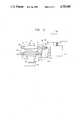
- FIG. 3is a front view illustrating an embodiment of the hand apparatus of the present invention.
- FIG. 4is a plane view of FIG. 3;
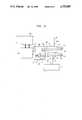
- FIG. 5is a front view showing deformation of the hand apparatus due to the reaction force generated when a workpiece is moved from the state of FIG. 3 to be set in position on the working table;
- FIG. 6is a front view showing a deformation of the hand apparatus (which has been rotated 180° from the orientation of FIG. 3) due to the reaction force generated when the hand apparatus grips a workpiece so as to set the workpiece in position on the working table, similarly to FIG. 5.
- FIGS. 3 and 4are diagrams showing an arrangement of an embodiment of the hand apparatus according to the present invention.
- FIG. 3is a front view and
- FIG. 4is a plane view of FIG. 3.
- a first hand 21has two first gripping pawls 22.
- a second hand 23 with its two second gripping pawls 24faces the opposite direction from that of the first hand 21.
- the first and second hands 21 and 23are fixed on a T-shaped common frame in opposition to each other in a plane portion of the frame 25.
- a first supporting arm 26is pivotally supported on one side arm of the frame 25 by a pin 28.
- a second supporting arm 27is pivotally supported on the other side arm of the frame 25 by a pin 29.
- a hand base 30has attached pins 31 and 32, and the first and second supporting arms 26 and 27 are pivotally supported by the pins 31 and 32, respectively.
- a third supporting arm 36pivotally supported by a pin 37.
- an energizing spring 35presses the third supporting arm 36.
- One end of the spring 35is fixed on a wall portion of the recess portion 30A, and the other end presses the movable third supporting arm 36.
- an energizing roller 34is located on a forward end portion of the third supporting arm 36 and is moved by the energizing spring 35 on the third supporting arm 36.
- the energizing roller 34is arranged to normally be forced against a V-shaped pressure receiving surface 33 formed on the first supporting arm 26 at its end portion.
- a rotary shaft 38is fixed to the base 30.
- a driving portion 39operates (rotates) the rotary shaft 38 and thereby the base 30 and the hands 21 and 23.
- the driving portion 39is connected to an arm 40 of an industrial robot.
- the thus-arranged hand apparatusmay be used so that the second gripping pawls 24 grip a workpiece 41 and set it in position on a working table 42.
- the distance that the arm 40 is moved in the downward directionexceeds such a value as to make the workpiece 41 contact the working table 42, the workpiece 41 is forced against the working table 42 so that a reaction force, corresponding to the force applied by the workpiece 41, causes the workpiece 41 to force up the T-shaped frame 25 through the intermediary second gripping pawls 24 and the second hand 23.
- the first and second supporting arms 26 and 27are rotated clockwise so as to rotate the energizing roller 34, which is forced against the V-shaped receiving surface 33 of the first supporting arm 26 at its end portion.
- the energizing spring 35receives and accommodates the reaction force generated between the workpiece 41 and the working table 42, as transmitted through the energizing roller 34 and the third supporting arm 36, to thereby lessen the reaction force.
- FIG. 6shows a reversal of the orientation of the first and second supporting arms 26 and 27, the pressure receiving surface 33, the energizing spring 35, etc., from their orientation shown in a balanced condition FIG. 3 and in an unbalanced condition in FIG. 5.
- the rotary shaft 38has been rotated by 180° by the rotating operating portion 39 from the state shown in FIG. 3 so that a workpiece 43 is gripped by the first gripper 21 rather than the second gripper 23, is set in position on the working table 42, and a reaction force is generated between the working table 42 and the workpiece 43.
- the energizing spring 35must have a sufficiently great spring constant and the pressure receiving surface 33 must have a sufficiently concave shape to operate such that the reaction force generated between the workpiece 41 or 43 and the working table 42 is absorbed and reduced by the energizing spring 35 through the respective members such as the frame 25, the first and second supporting arms 26 and 27, etc.
- the first and second supporting arms 26 and 27are maintained at their attitudes in the form of horizontal cantilevers so as to sufficiently bear the respective weights of the T-shaped frame 25, the first and second supporting arms 26 and 27, the workpiece 41 or 43, etc.
- a workpiececan be moved by either hand, and it is possible to absorb reaction force generated between the work table and the workpiece by the interaction of the pressure receiving portion formed at one end of the supporting arm and the energizing spring. Moreover, it is possible to considerably simplify the mechanism for absorbing the reaction force as well as to correctly set a workpiece.
Landscapes
- Engineering & Computer Science (AREA)
- Robotics (AREA)
- Mechanical Engineering (AREA)
- Manipulator (AREA)
Abstract
Description
Claims (13)
Applications Claiming Priority (2)
| Application Number | Priority Date | Filing Date | Title |
|---|---|---|---|
| JP60050531AJPH066276B2 (en) | 1985-03-15 | 1985-03-15 | Industrial robot hand device |
| JP60-50531 | 1985-03-15 |
Publications (1)
| Publication Number | Publication Date |
|---|---|
| US4725087Atrue US4725087A (en) | 1988-02-16 |
Family
ID=12861573
Family Applications (1)
| Application Number | Title | Priority Date | Filing Date |
|---|---|---|---|
| US06/839,381Expired - Fee RelatedUS4725087A (en) | 1985-03-15 | 1986-03-14 | Spring-loaded hand for an industrial robot |
Country Status (2)
| Country | Link |
|---|---|
| US (1) | US4725087A (en) |
| JP (1) | JPH066276B2 (en) |
Cited By (10)
| Publication number | Priority date | Publication date | Assignee | Title |
|---|---|---|---|---|
| EP0670202A1 (en)* | 1994-02-28 | 1995-09-06 | Director-General of Agency of Industrial Science and Technology, Jiro Hiraishi | Forging robot hand |
| EP0683019A1 (en)* | 1994-05-16 | 1995-11-22 | Director-General of Agency of Industrial Science and Technology | Robot which is capable of receiving impact load |
| EP2006055A1 (en)* | 2007-06-22 | 2008-12-24 | Deutsches Zentrum für Luft- und Raumfahrt e.V. | Robot-manipulator articulated drive with torque support |
| EP3062957A4 (en)* | 2013-10-31 | 2017-07-26 | Anca Pty Ltd | Tool gripper arrangement |
| USD865826S1 (en)* | 2017-07-14 | 2019-11-05 | Nitta Corporation | Gripper for industrial robot |
| USD866626S1 (en)* | 2017-07-14 | 2019-11-12 | Nitta Corporation | Gripper for industrial robot |
| USD869532S1 (en)* | 2017-07-14 | 2019-12-10 | Nitta Corporation | Gripper for industrial robot |
| USD870170S1 (en) | 2016-11-21 | 2019-12-17 | Nitta Corporation | Gripper for industrial robot |
| USD894247S1 (en)* | 2017-09-11 | 2020-08-25 | Smc Corporation | Gripper |
| USD900182S1 (en)* | 2017-04-23 | 2020-10-27 | Franka Emika Gmbh | Gripper for robot |
Families Citing this family (2)
| Publication number | Priority date | Publication date | Assignee | Title |
|---|---|---|---|---|
| JPH0810524Y2 (en)* | 1990-03-26 | 1996-03-29 | 株式会社安川電機 | Horizontal articulated robot |
| US5355634A (en)* | 1991-05-24 | 1994-10-18 | Yamaha Corporation | Tool holder unit for a robot |
Citations (9)
| Publication number | Priority date | Publication date | Assignee | Title |
|---|---|---|---|---|
| US1807360A (en)* | 1928-03-17 | 1931-05-26 | Cleveland Crane Eng | Paper roll handling mechanism |
| US3289485A (en)* | 1964-07-24 | 1966-12-06 | Commissariat Energie Atomique | Leak-tight coupling device for master-slave manipulator |
| GB1068877A (en)* | 1964-08-20 | 1967-05-17 | Schwermaschb Heinrich Rau Veb | Improvements in and relating to manipulators for forgings |
| US3652117A (en)* | 1966-05-14 | 1972-03-28 | Herbert Schroder | Equipment for manufacturing bakery products |
| DE2717221A1 (en)* | 1977-04-19 | 1978-11-02 | Theysohn Friedrich Fa | Simple industrial robot for handling plastics mouldings - has pneumatic or hydraulic actuation of parallelogram linkage |
| SU1000271A1 (en)* | 1981-11-13 | 1983-02-28 | Всесоюзный заочный машиностроительный институт | Balanced manipulator |
| US4416577A (en)* | 1980-08-06 | 1983-11-22 | Fujitsu Fanuc Limited | Robot hand of an industrial robot |
| EP0114096A1 (en)* | 1983-01-13 | 1984-07-25 | Western Electric Company, Incorporated | Robotic arm |
| US4592697A (en)* | 1983-04-26 | 1986-06-03 | Kabushiki Kaisha Kobe Seiko Sho | Gravity balancing device for rocking arm |
- 1985
- 1985-03-15JPJP60050531Apatent/JPH066276B2/ennot_activeExpired - Lifetime
- 1986
- 1986-03-14USUS06/839,381patent/US4725087A/ennot_activeExpired - Fee Related
Patent Citations (9)
| Publication number | Priority date | Publication date | Assignee | Title |
|---|---|---|---|---|
| US1807360A (en)* | 1928-03-17 | 1931-05-26 | Cleveland Crane Eng | Paper roll handling mechanism |
| US3289485A (en)* | 1964-07-24 | 1966-12-06 | Commissariat Energie Atomique | Leak-tight coupling device for master-slave manipulator |
| GB1068877A (en)* | 1964-08-20 | 1967-05-17 | Schwermaschb Heinrich Rau Veb | Improvements in and relating to manipulators for forgings |
| US3652117A (en)* | 1966-05-14 | 1972-03-28 | Herbert Schroder | Equipment for manufacturing bakery products |
| DE2717221A1 (en)* | 1977-04-19 | 1978-11-02 | Theysohn Friedrich Fa | Simple industrial robot for handling plastics mouldings - has pneumatic or hydraulic actuation of parallelogram linkage |
| US4416577A (en)* | 1980-08-06 | 1983-11-22 | Fujitsu Fanuc Limited | Robot hand of an industrial robot |
| SU1000271A1 (en)* | 1981-11-13 | 1983-02-28 | Всесоюзный заочный машиностроительный институт | Balanced manipulator |
| EP0114096A1 (en)* | 1983-01-13 | 1984-07-25 | Western Electric Company, Incorporated | Robotic arm |
| US4592697A (en)* | 1983-04-26 | 1986-06-03 | Kabushiki Kaisha Kobe Seiko Sho | Gravity balancing device for rocking arm |
Cited By (13)
| Publication number | Priority date | Publication date | Assignee | Title |
|---|---|---|---|---|
| EP0670202A1 (en)* | 1994-02-28 | 1995-09-06 | Director-General of Agency of Industrial Science and Technology, Jiro Hiraishi | Forging robot hand |
| EP0683019A1 (en)* | 1994-05-16 | 1995-11-22 | Director-General of Agency of Industrial Science and Technology | Robot which is capable of receiving impact load |
| EP2006055A1 (en)* | 2007-06-22 | 2008-12-24 | Deutsches Zentrum für Luft- und Raumfahrt e.V. | Robot-manipulator articulated drive with torque support |
| EP3062957A4 (en)* | 2013-10-31 | 2017-07-26 | Anca Pty Ltd | Tool gripper arrangement |
| US9919396B2 (en) | 2013-10-31 | 2018-03-20 | Anca Pty Ltd | Tool gripper arrangement |
| USD871473S1 (en)* | 2016-11-21 | 2019-12-31 | Nitta Corporation | Gripper for industrial robot |
| USD870170S1 (en) | 2016-11-21 | 2019-12-17 | Nitta Corporation | Gripper for industrial robot |
| USD871479S1 (en) | 2016-11-21 | 2019-12-31 | Nitta Corporation | Gripper for industrial robot |
| USD900182S1 (en)* | 2017-04-23 | 2020-10-27 | Franka Emika Gmbh | Gripper for robot |
| USD866626S1 (en)* | 2017-07-14 | 2019-11-12 | Nitta Corporation | Gripper for industrial robot |
| USD869532S1 (en)* | 2017-07-14 | 2019-12-10 | Nitta Corporation | Gripper for industrial robot |
| USD865826S1 (en)* | 2017-07-14 | 2019-11-05 | Nitta Corporation | Gripper for industrial robot |
| USD894247S1 (en)* | 2017-09-11 | 2020-08-25 | Smc Corporation | Gripper |
Also Published As
| Publication number | Publication date |
|---|---|
| JPS61214991A (en) | 1986-09-24 |
| JPH066276B2 (en) | 1994-01-26 |
Similar Documents
| Publication | Publication Date | Title |
|---|---|---|
| US4725087A (en) | Spring-loaded hand for an industrial robot | |
| US5108140A (en) | Reconfigurable end effector | |
| US4505636A (en) | Robot machines | |
| US4544193A (en) | Robot grippers | |
| US5178431A (en) | Double-V block fingers with cruciform recess | |
| FR2424795B1 (en) | ||
| JPH0474152B2 (en) | ||
| JPS63251186A (en) | robot hand | |
| US4834440A (en) | Hand device for industrial robot | |
| JPH0460779B2 (en) | ||
| KR102438732B1 (en) | Gripper for rotating workpieces | |
| JP2553995Y2 (en) | Industrial manipulator | |
| CN220094633U (en) | Robot gripper | |
| JPS6333971B2 (en) | ||
| SU1119842A1 (en) | Gripper | |
| SU1306711A1 (en) | Gripping device of mechanical arm | |
| JPS584384A (en) | mechanical hand | |
| JPH05196B2 (en) | ||
| JPH042395B2 (en) | ||
| CN211073631U (en) | Mechanical gripper and robot with same | |
| SU841963A1 (en) | Manipulator arm | |
| SU1315299A1 (en) | Manipulator | |
| KR930001855Y1 (en) | Robot finger | |
| SU1247265A1 (en) | Manipulator arm | |
| JPS637294A (en) | gripping device |
Legal Events
| Date | Code | Title | Description |
|---|---|---|---|
| AS | Assignment | Owner name:MITSUBISHI DENKI KABUSHIKI KAISHA, NO. 2-3, MARUNO Free format text:ASSIGNMENT OF ASSIGNORS INTEREST.;ASSIGNOR:KATO, HISAO;REEL/FRAME:004789/0530 Effective date:19860306 Owner name:MITSUBISHI DENKI KABUSHIKI KAISHA, NO. 2-3, MARUNO Free format text:ASSIGNMENT OF ASSIGNORS INTEREST;ASSIGNOR:KATO, HISAO;REEL/FRAME:004789/0530 Effective date:19860306 | |
| FEPP | Fee payment procedure | Free format text:PAYOR NUMBER ASSIGNED (ORIGINAL EVENT CODE: ASPN); ENTITY STATUS OF PATENT OWNER: LARGE ENTITY | |
| FPAY | Fee payment | Year of fee payment:4 | |
| FEPP | Fee payment procedure | Free format text:PAYER NUMBER DE-ASSIGNED (ORIGINAL EVENT CODE: RMPN); ENTITY STATUS OF PATENT OWNER: LARGE ENTITY Free format text:PAYOR NUMBER ASSIGNED (ORIGINAL EVENT CODE: ASPN); ENTITY STATUS OF PATENT OWNER: LARGE ENTITY | |
| REMI | Maintenance fee reminder mailed | ||
| LAPS | Lapse for failure to pay maintenance fees | ||
| FP | Lapsed due to failure to pay maintenance fee | Effective date:19960221 | |
| STCH | Information on status: patent discontinuation | Free format text:PATENT EXPIRED DUE TO NONPAYMENT OF MAINTENANCE FEES UNDER 37 CFR 1.362 |