US4725029A - Brake booster mounting arrangement - Google Patents
Brake booster mounting arrangementDownload PDFInfo
- Publication number
- US4725029A US4725029AUS06/914,997US91499786AUS4725029AUS 4725029 AUS4725029 AUS 4725029AUS 91499786 AUS91499786 AUS 91499786AUS 4725029 AUS4725029 AUS 4725029A
- Authority
- US
- United States
- Prior art keywords
- mounting
- nut
- booster
- brake booster
- support wall
- Prior art date
- Legal status (The legal status is an assumption and is not a legal conclusion. Google has not performed a legal analysis and makes no representation as to the accuracy of the status listed.)
- Expired - Fee Related
Links
- 238000007373indentationMethods0.000abstractdescription4
- 230000003014reinforcing effectEffects0.000description3
- 238000005452bendingMethods0.000description1
- 238000003780insertionMethods0.000description1
- 230000037431insertionEffects0.000description1
- 238000000034methodMethods0.000description1
- XLYOFNOQVPJJNP-UHFFFAOYSA-NwaterSubstancesOXLYOFNOQVPJJNP-UHFFFAOYSA-N0.000description1
- 238000003466weldingMethods0.000description1
Images


Classifications
- B—PERFORMING OPERATIONS; TRANSPORTING
- B60—VEHICLES IN GENERAL
- B60T—VEHICLE BRAKE CONTROL SYSTEMS OR PARTS THEREOF; BRAKE CONTROL SYSTEMS OR PARTS THEREOF, IN GENERAL; ARRANGEMENT OF BRAKING ELEMENTS ON VEHICLES IN GENERAL; PORTABLE DEVICES FOR PREVENTING UNWANTED MOVEMENT OF VEHICLES; VEHICLE MODIFICATIONS TO FACILITATE COOLING OF BRAKES
- B60T13/00—Transmitting braking action from initiating means to ultimate brake actuator with power assistance or drive; Brake systems incorporating such transmitting means, e.g. air-pressure brake systems
- F—MECHANICAL ENGINEERING; LIGHTING; HEATING; WEAPONS; BLASTING
- F16—ENGINEERING ELEMENTS AND UNITS; GENERAL MEASURES FOR PRODUCING AND MAINTAINING EFFECTIVE FUNCTIONING OF MACHINES OR INSTALLATIONS; THERMAL INSULATION IN GENERAL
- F16B—DEVICES FOR FASTENING OR SECURING CONSTRUCTIONAL ELEMENTS OR MACHINE PARTS TOGETHER, e.g. NAILS, BOLTS, CIRCLIPS, CLAMPS, CLIPS OR WEDGES; JOINTS OR JOINTING
- F16B21/00—Means for preventing relative axial movement of a pin, spigot, shaft or the like and a member surrounding it; Stud-and-socket releasable fastenings
- F16B21/09—Releasable fastening devices with a stud engaging a keyhole slot
- B—PERFORMING OPERATIONS; TRANSPORTING
- B60—VEHICLES IN GENERAL
- B60R—VEHICLES, VEHICLE FITTINGS, OR VEHICLE PARTS, NOT OTHERWISE PROVIDED FOR
- B60R11/00—Arrangements for holding or mounting articles, not otherwise provided for
- B—PERFORMING OPERATIONS; TRANSPORTING
- B60—VEHICLES IN GENERAL
- B60T—VEHICLE BRAKE CONTROL SYSTEMS OR PARTS THEREOF; BRAKE CONTROL SYSTEMS OR PARTS THEREOF, IN GENERAL; ARRANGEMENT OF BRAKING ELEMENTS ON VEHICLES IN GENERAL; PORTABLE DEVICES FOR PREVENTING UNWANTED MOVEMENT OF VEHICLES; VEHICLE MODIFICATIONS TO FACILITATE COOLING OF BRAKES
- B60T13/00—Transmitting braking action from initiating means to ultimate brake actuator with power assistance or drive; Brake systems incorporating such transmitting means, e.g. air-pressure brake systems
- B60T13/10—Transmitting braking action from initiating means to ultimate brake actuator with power assistance or drive; Brake systems incorporating such transmitting means, e.g. air-pressure brake systems with fluid assistance, drive, or release
- B60T13/24—Transmitting braking action from initiating means to ultimate brake actuator with power assistance or drive; Brake systems incorporating such transmitting means, e.g. air-pressure brake systems with fluid assistance, drive, or release the fluid being gaseous
- B60T13/46—Vacuum systems
- B60T13/52—Vacuum systems indirect, i.e. vacuum booster units
- B60T13/567—Vacuum systems indirect, i.e. vacuum booster units characterised by constructional features of the casing or by its strengthening or mounting arrangements
- B60T13/5675—Supportstruts
- Y—GENERAL TAGGING OF NEW TECHNOLOGICAL DEVELOPMENTS; GENERAL TAGGING OF CROSS-SECTIONAL TECHNOLOGIES SPANNING OVER SEVERAL SECTIONS OF THE IPC; TECHNICAL SUBJECTS COVERED BY FORMER USPC CROSS-REFERENCE ART COLLECTIONS [XRACs] AND DIGESTS
- Y10—TECHNICAL SUBJECTS COVERED BY FORMER USPC
- Y10T—TECHNICAL SUBJECTS COVERED BY FORMER US CLASSIFICATION
- Y10T403/00—Joints and connections
- Y10T403/70—Interfitted members
- Y10T403/7005—Lugged member, rotary engagement
Definitions
- the inventionrelates to an arrangement attaching a brake booster to the firewall of a vehicle, for example, an automobile, and more particularly to a mounting assembly therefor.
- a brake boosteris mounted to the firewall of a vehicle by securing at least two shaped nuts to the housing of the brake booster, each nut having a first portion having a first diameter, and a second portion having a second diameter, the second portion being adjacent the first portion and the second diameter having a value less than that of the first diameter; passing the first portion of each nut through corresponding apertures in the firewall or in a mounting bracket secured to the firewall, each aperture comprising two regions, a first region having a diameter large enough to allow passage of the first portion of the nut through the aperture, and a second region having a diameter having a value greater than that of the second portion of the nut but less than that of the first portion of the nut, the second region opening into the first region; moving the brake booster relative to the firewall from the nut insertion position to a securing position such that the second portion of each nut moves into the second region of its corresponding aperture; and releasably locking the brake booster in the securing position.
- the nutsare secured to the housing of the brake booster by welding.
- the housingalready has threaded studs secured to it, nuts having a threaded aperture may be used, the nuts being screw threaded to the studs.
- Resilient meansis preferably positioned on the opposite side of the firewall or mounting bracket to the first portion of each nut when the brake booster is in the securing position, the resilient means engaging the housing of the brake booster and the firewall or mounting bracket to resilient bias the first portion of each nut against the firewall or mounting bracket.
- the resilient meansmay be in the form of a helical coil spring positioned around each nut.
- the resilient meansis in the form of a spring plate attached to the nuts.
- the spring plateis preferably attached to the nuts by passing the nuts through holes in the plate, at least one of the holes being so shaped and sized as to resiliently grip its corresponding nut.
- the spring plateis preferably attached by passing the studs through clearance holes in the plate and then screw threading the nuts to the studs to secure the spring plate to the housing.
- the spring platehas an extending finger with a lip or detent at its free end which releasably latches in a corresponding opening or indentation in the firewall or mounting bracket when the brake booster is in the securing position to releasably lock the brake booster in the securing position.
- the brake boosteris moved relative to the firewall or mounting bracket by rotational movement.
- the relative movementmay be lateral movement.
- FIG. 1is an end view, with parts broken away and in section, of a mounting assembly in accordance with this invention
- FIG. 2is a view in the direction II in FIG. 1 of the spring plate of the assembly
- FIG. 3is a cross-sectional view with parts broken away, taken on the line III--III in FIG. 1;
- FIG. 4is a fragmentary cross-section view taken on the line IV--IV in FIG. 1;
- FIGS. 5 to 8are identical views of FIGS. 1 to 4 respectively of an alternative mounting arrangement in accordance with the invention.
- a firewall 1 of a vehicleis shown.
- the firewall 1has a reinforcing plate 2, and a brake booster 3 is attached to the firewall.
- the brake booster 3is attached by four nuts 4 which are preferably welded to the housing 5 of the brake booster.
- Each nut 4has a first portion 6 having a first diameter and a second portion 7, adjacent the first portion, having a second diameter which is of lesser value than the value of the first diameter.
- each nut 4has been passed through a corresponding aperture 8 in the firewall 1 and reinforcing plate 2.
- Each aperture 8has two regions, a first region 9 having a diameter large enough to allow passage of the first portion 6 of the nut 4 through the aperture, and a second region 10 having a diameter having a value greater than that of the second portion 7 of the nut, but less than that of the first portion of the nut, the second region opening into the first region.
- the brake booster 3is positioned by passing the first portion 6 of each nut 4 through the first region 9 of its corresponding aperture 8 and then rotating the brake booster relative to the firewall 1 to its securing position (as shown in FIG. 1) such that the second portion 7 of each nut moves into the second region 10 of its corresponding aperture.
- Resilient means in the form of a spring plate 11is positioned between the housing 5 of the brake booster 3 and the firewall 1, on the opposite side of the firewall to the first portion 6 of each nut 4, when the brake booster is in the securing position.
- the spring plate 11biases the first portion 6 of each nut 4 against the reinforcing plate 3, and hence against the firewall 1.
- the spring plate 11is secured to the housing 5 of the brake booster 3 by passing the nuts 4 through holes 12 in the plate 11, the holes being shaped and sized to resiliently grip the nuts.
- the spring plate 11also has an extending finger 13 with a lip or detent 14 at its free end 15.
- the detent 14releasably latches in an indentation 16 in the firewall 1 when the brake booster 3 is in the securing position, to releasably lock the brake booster in position.
- the locking actioncan be disengaged (for removal of the brake booster 3) by bending the finger 13 to move the detent 14 out of the indentation 16.
- the brake booster 3can then be rotated relative to the firewall 1 for removal.
- An elastomeric O-ring 17is positioned between the extending finger 13 and the firewall 1 to substantially prevent ingress of water into the firewall area, and to suppress noise and vibration.
- FIGS. 5 to 8show a similar arrangement in which similar parts have been given the same reference numbers.
- the brake booster 3is laterally moved relative to the firewall 1 to secure the brake booster in position.
- the brake boostermay be attached to a mounting bracket which is secured to the firewall.
- the nutsmay be attached to the housing of the brake booster by screw threading to threaded studs attached to the housing. This latter arrangement allows previous designs of brake booster, which may already have threaded studs on them, to be attached to the firewall using this invention.
Landscapes
- Engineering & Computer Science (AREA)
- Mechanical Engineering (AREA)
- General Engineering & Computer Science (AREA)
- Transportation (AREA)
- Braking Systems And Boosters (AREA)
Abstract
Description
Claim of priority based on British Application No. 8524569, filed Oct. 4, 1985.
The invention relates to an arrangement attaching a brake booster to the firewall of a vehicle, for example, an automobile, and more particularly to a mounting assembly therefor.
It has been the practice for a number of years to attach the brake booster to an automobile to the firewall by using nuts and bolts or threaded studs. This method, however, is very time consuming.
According to the present invention, a brake booster is mounted to the firewall of a vehicle by securing at least two shaped nuts to the housing of the brake booster, each nut having a first portion having a first diameter, and a second portion having a second diameter, the second portion being adjacent the first portion and the second diameter having a value less than that of the first diameter; passing the first portion of each nut through corresponding apertures in the firewall or in a mounting bracket secured to the firewall, each aperture comprising two regions, a first region having a diameter large enough to allow passage of the first portion of the nut through the aperture, and a second region having a diameter having a value greater than that of the second portion of the nut but less than that of the first portion of the nut, the second region opening into the first region; moving the brake booster relative to the firewall from the nut insertion position to a securing position such that the second portion of each nut moves into the second region of its corresponding aperture; and releasably locking the brake booster in the securing position.
Using this arrangement, the assembly time is considerably reduced as compared to typical stud through-bolt mounting arrangements in current use.
Preferably, the nuts are secured to the housing of the brake booster by welding. Alternatively, where the housing already has threaded studs secured to it, nuts having a threaded aperture may be used, the nuts being screw threaded to the studs.
Resilient means is preferably positioned on the opposite side of the firewall or mounting bracket to the first portion of each nut when the brake booster is in the securing position, the resilient means engaging the housing of the brake booster and the firewall or mounting bracket to resilient bias the first portion of each nut against the firewall or mounting bracket.
The resilient means may be in the form of a helical coil spring positioned around each nut. Preferably, however, the resilient means is in the form of a spring plate attached to the nuts. Where the nuts are welded to the housing, the spring plate is preferably attached to the nuts by passing the nuts through holes in the plate, at least one of the holes being so shaped and sized as to resiliently grip its corresponding nut. Where the nuts are screw threaded to studs on the housing, the spring plate is preferably attached by passing the studs through clearance holes in the plate and then screw threading the nuts to the studs to secure the spring plate to the housing.
Preferably the spring plate has an extending finger with a lip or detent at its free end which releasably latches in a corresponding opening or indentation in the firewall or mounting bracket when the brake booster is in the securing position to releasably lock the brake booster in the securing position.
Preferably there are four nuts, and the brake booster is moved relative to the firewall or mounting bracket by rotational movement. Alternatively, in this case, the relative movement may be lateral movement.
The invention is further described, by way of example, with reference to the accompany drawings in which:
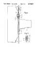
FIG. 1 is an end view, with parts broken away and in section, of a mounting assembly in accordance with this invention;
FIG. 2 is a view in the direction II in FIG. 1 of the spring plate of the assembly;
FIG. 3 is a cross-sectional view with parts broken away, taken on the line III--III in FIG. 1;
FIG. 4 is a fragmentary cross-section view taken on the line IV--IV in FIG. 1; and
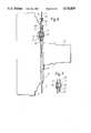
FIGS. 5 to 8 are identical views of FIGS. 1 to 4 respectively of an alternative mounting arrangement in accordance with the invention.
Referring to FIGS. 1 to 4, a firewall 1 of a vehicle is shown. The firewall 1 has a reinforcingplate 2, and abrake booster 3 is attached to the firewall. Thebrake booster 3 is attached by four nuts 4 which are preferably welded to thehousing 5 of the brake booster. Each nut 4 has afirst portion 6 having a first diameter and asecond portion 7, adjacent the first portion, having a second diameter which is of lesser value than the value of the first diameter.
Thefirst portion 6 of each nut 4 has been passed through acorresponding aperture 8 in the firewall 1 and reinforcingplate 2. Eachaperture 8 has two regions, a first region 9 having a diameter large enough to allow passage of thefirst portion 6 of the nut 4 through the aperture, and asecond region 10 having a diameter having a value greater than that of thesecond portion 7 of the nut, but less than that of the first portion of the nut, the second region opening into the first region.
Thebrake booster 3 is positioned by passing thefirst portion 6 of each nut 4 through the first region 9 of itscorresponding aperture 8 and then rotating the brake booster relative to the firewall 1 to its securing position (as shown in FIG. 1) such that thesecond portion 7 of each nut moves into thesecond region 10 of its corresponding aperture.
Resilient means in the form of aspring plate 11 is positioned between thehousing 5 of thebrake booster 3 and the firewall 1, on the opposite side of the firewall to thefirst portion 6 of each nut 4, when the brake booster is in the securing position. Thespring plate 11 biases thefirst portion 6 of each nut 4 against the reinforcingplate 3, and hence against the firewall 1. Thespring plate 11 is secured to thehousing 5 of thebrake booster 3 by passing the nuts 4 throughholes 12 in theplate 11, the holes being shaped and sized to resiliently grip the nuts.
Thespring plate 11 also has an extendingfinger 13 with a lip or detent 14 at itsfree end 15. The detent 14 releasably latches in anindentation 16 in the firewall 1 when thebrake booster 3 is in the securing position, to releasably lock the brake booster in position. The locking action can be disengaged (for removal of the brake booster 3) by bending thefinger 13 to move the detent 14 out of theindentation 16. Thebrake booster 3 can then be rotated relative to the firewall 1 for removal.
An elastomeric O-ring 17 is positioned between the extendingfinger 13 and the firewall 1 to substantially prevent ingress of water into the firewall area, and to suppress noise and vibration.
FIGS. 5 to 8 show a similar arrangement in which similar parts have been given the same reference numbers. In this case, thebrake booster 3 is laterally moved relative to the firewall 1 to secure the brake booster in position.
In alternative arrangements the brake booster may be attached to a mounting bracket which is secured to the firewall. Further, the nuts may be attached to the housing of the brake booster by screw threading to threaded studs attached to the housing. This latter arrangement allows previous designs of brake booster, which may already have threaded studs on them, to be attached to the firewall using this invention.
Claims (2)
1. For use in a vehicle having a brake booster mounted therein, a brake booster mounting arrangement comprising:
a booster mounting support wall forming a part of the vehicle, a brake booster having a housing, a plurality of shaped nut-like mounting members secured to said brake booster housing in circumferentially spaced relation, each of said nut-like mounting members having a first portion having a first diameter and a second portion having a second diameter, said second portion being adjacent said first portion and said second diameter having a value less than the value of said first diameter;
said booster mounting support wall having a center opening receiving a portion of said booster housing therethrough and detent-receiving means positioned radially outward of said center opening, said support wall also having apertures therein spaced circumferentially about said center opening corresponding to said nut-like mounting members, each of said apertures comprising a first region having a diameter large enough to allow passage therethrough and a second region having a diameter of a value greater than the value of said nut-like mounting member second portion second diameter but less than the value of said nut-like mounting member first portion first diameter, said second region opening into said first region;
said first region of each of said apertures being adapted to receive the first portion of one of said nut-like mounting members therethrough and then permit movement of said nut-like mounting members to a second position in which said second portion of each of said nut-like mounting members is then received within said second region of its corresponding aperture, said second position being the position thereof with the brake booster mounted in the vehicle;
resilient spring plate means surrounding said support wall center opening said spring plate means having circumferentially spaced openings through which said nut-like mounting members are received with said spring plate means being and positioned on and operatively secured to said nut-like mounting members and resiliently engaging said booster mounting support wall and said booster housing at alternate circumferentially spaced positions about said mounting wall opening and biasing said booster housing away from said booster mounting support wall and therefore biasing said spring nut-like mounting member first portions against the other side of said booster mounting support wall from said booster housing, said resilient means including at least one spring loaded arm extending outwardly therefrom between said booster housing and said support wall, said arm having a detent formed on the outer end thereof, said detent cooperating with said mounting support wall detent-receiving means to releasably lock said brake booster to said mounting support wall against rotation and in the secured position.
2. The brake booster mounting arrangement of claim 1 in which said mounting support wall is the vehicle firewall in combination with a mounting bracket secured to said firewall with said apertures being formed through said firewall and said mounting bracket.
Applications Claiming Priority (2)
| Application Number | Priority Date | Filing Date | Title |
|---|---|---|---|
| GB8524569 | 1985-10-04 | ||
| GB08524569AGB2181178A (en) | 1985-10-04 | 1985-10-04 | A method of attaching a brake booster to a vehicle |
Publications (1)
| Publication Number | Publication Date |
|---|---|
| US4725029Atrue US4725029A (en) | 1988-02-16 |
Family
ID=10586221
Family Applications (1)
| Application Number | Title | Priority Date | Filing Date |
|---|---|---|---|
| US06/914,997Expired - Fee RelatedUS4725029A (en) | 1985-10-04 | 1986-10-03 | Brake booster mounting arrangement |
Country Status (8)
| Country | Link |
|---|---|
| US (1) | US4725029A (en) |
| JP (1) | JPS6285755A (en) |
| KR (1) | KR870003905A (en) |
| DE (1) | DE3629181A1 (en) |
| ES (1) | ES2002404A6 (en) |
| FR (1) | FR2588331A1 (en) |
| GB (1) | GB2181178A (en) |
| IT (1) | IT1201070B (en) |
Cited By (29)
| Publication number | Priority date | Publication date | Assignee | Title |
|---|---|---|---|---|
| US4844565A (en)* | 1988-01-11 | 1989-07-04 | Unisys Corporation | Quick-release spacer-latching-connector assembly |
| US4941764A (en)* | 1988-09-15 | 1990-07-17 | Alfred Teves Gmbh | Arrangement for fastening a brake booster |
| US4955197A (en)* | 1989-09-11 | 1990-09-11 | General Motors Corporation | Master cylinder attachment adapter |
| US5011234A (en)* | 1988-07-04 | 1991-04-30 | Alfred Teves Gmbh | Arrangement for mounting a brake power booster |
| US5012998A (en)* | 1988-11-30 | 1991-05-07 | Bendix France | Device for assembling a servomotor on a vehicle bulkhead |
| US5056412A (en)* | 1988-10-28 | 1991-10-15 | Bendix France | Brake servomotor assembly mounted on a stationary wall of a vehicle |
| US5215332A (en)* | 1990-05-21 | 1993-06-01 | General Motors Corporation | Quick release seat belt anchor |
| US5232303A (en)* | 1990-05-22 | 1993-08-03 | Wilkhahn Wilkening + Hahne Gmbh + Co. | Connecting arrangement |
| US5420762A (en)* | 1993-09-24 | 1995-05-30 | Trw Inc. | Automotive headlamp assembly fastening system |
| US5685407A (en)* | 1994-02-26 | 1997-11-11 | Fichtel & Sachs Ag | Transmission device for a motor vehicle |
| US6071034A (en)* | 1997-01-21 | 2000-06-06 | Sipex S.N.C. Di Cavagna Livio & C. | Quick-coupling device, particularly for applying a cover to water closet |
| US6318276B1 (en)* | 1999-09-18 | 2001-11-20 | Dauphin Entwicklungs-U. Beteilingungs-Gmbh | Table unit |
| US6398179B1 (en) | 2000-01-19 | 2002-06-04 | General Motors Corporation | Fastener-less spring assembly |
| US6527035B2 (en)* | 2000-07-06 | 2003-03-04 | Overhead Door Corporation | Guide track assemblies and mounting brackets for upward acting doors |
| US20030052293A1 (en)* | 2001-09-18 | 2003-03-20 | Smc Corporation | Maintenance-easy two-port valve |
| US6905178B1 (en)* | 2004-02-19 | 2005-06-14 | Robert Bosch Gmbh | Spacer for a boost unit |
| US20050139062A1 (en)* | 2003-12-24 | 2005-06-30 | Robert Bosch Gmbh | Arrangement for the bayonet-fixing and locking of a brake booster |
| US20070102605A1 (en)* | 2005-10-27 | 2007-05-10 | Vela Francisco R | Arrangement and method for fitting a brake assist device in a motor vehicle |
| US20080107479A1 (en)* | 2006-11-07 | 2008-05-08 | Inventec Corporation | Fan fixing apparatus |
| US20090038690A1 (en)* | 2007-08-08 | 2009-02-12 | Deltrol Controls | Solenoid mounting arrangement for liquid dispensing valve |
| US20100050425A1 (en)* | 2008-08-29 | 2010-03-04 | Inventec Corporation | Rotary positioning mechanism |
| US20110132189A1 (en)* | 2009-12-08 | 2011-06-09 | Fisher Albert D | Vibration/Shock Resistant Stud Housing |
| US20110290971A1 (en)* | 2010-06-01 | 2011-12-01 | Peerless Industries, Inc | Adjustable display bracket |
| US20130062489A1 (en)* | 2011-09-08 | 2013-03-14 | Visor Frames, LLC | Rotating Attachment Device and Method of Use |
| CN103068646A (en)* | 2010-08-19 | 2013-04-24 | 卢卡斯汽车股份有限公司 | Vacuum brake booster having an assembly-friendly chamber arrangement and method for assembling a vacuum brake booster |
| CN103569216A (en)* | 2013-10-30 | 2014-02-12 | 上海双杰科技有限公司 | Wheel house panel mounting structure |
| US20150131214A1 (en)* | 2013-11-14 | 2015-05-14 | Hong Fu Jin Precision Industry (Shenzhen) Co., Ltd | Electronic device with support |
| US9206634B1 (en)* | 2013-03-15 | 2015-12-08 | Overhead Door Corporation | Counterbalance system for vertical acting doors |
| US10758037B2 (en)* | 2016-09-16 | 2020-09-01 | Oahwip B.V. | Quick assembly desk |
Families Citing this family (19)
| Publication number | Priority date | Publication date | Assignee | Title |
|---|---|---|---|---|
| DE3613329C1 (en)* | 1986-04-19 | 1987-07-02 | Ford Werke Ag | Device for attaching an object to a body wall of a motor vehicle |
| DE4037752C1 (en)* | 1990-11-28 | 1992-07-16 | Karl Lautenschlaeger Gmbh & Co Kg Moebelbeschlagfabrik, 6107 Reinheim, De | |
| GB2259339A (en)* | 1991-09-07 | 1993-03-10 | Automotive Products Plc | Brake booster mounting |
| DE4204419A1 (en)* | 1992-02-14 | 1993-08-19 | Teves Gmbh Alfred | Actuator for vehicle hydraulic brake - uses connecting bolts for booster housing pulled tight against back of vehicle wall |
| JPH07255282A (en)* | 1994-03-18 | 1995-10-09 | Nichifu Co Ltd | Soil bed-insulating unit of container for plant culture |
| JPH07255283A (en)* | 1994-03-18 | 1995-10-09 | Nichifu Co Ltd | Container for plant culture |
| JP3165321B2 (en)* | 1994-04-14 | 2001-05-14 | ホーチキ株式会社 | Fire detector and detector body removal device |
| GB2325018B (en)* | 1997-05-07 | 2001-11-28 | Rafiki Prot Ltd | Housings |
| FR2770478B1 (en)* | 1997-10-30 | 1999-12-17 | Bosch Syst Freinage | BRAKE ASSISTANCE DEVICE WITH SIMPLIFIED ASSEMBLY |
| DE19836416A1 (en)* | 1998-08-12 | 2000-02-24 | Ludwig Schatzinger | Wall fastening system for flat picture or CD-cassette incorporates baseplate with angled distance piece and interlocking fastening engaging fastening on back of picture or on cassette |
| FR2843575B1 (en)* | 2002-08-13 | 2004-11-12 | Bosch Gmbh Robert | ARRANGEMENT FOR THE BAYONET FIXING OF A BRAKE ASSIST MOTOR |
| WO2005042326A1 (en)* | 2003-08-15 | 2005-05-12 | Robert Bosch Gmbh | Bayonet fixing for a servo motor for power assisted braking |
| FR2908847B1 (en)* | 2006-11-20 | 2010-12-24 | Faurecia Bloc Avant | ASSEMBLY FOR A MOTOR VEHICLE, IN PARTICULAR FOR ASSEMBLING A WING AND A WING EXPANSION. |
| DE102008028056A1 (en)* | 2008-06-12 | 2009-12-17 | Volkswagen Ag | Power brake unit for fixing at dashboard of motor vehicle, has hook projection comprising head provided at end of neck and sectionally projecting opposite to neck in radial manner, where head is narrow at free end |
| DE102009035670A1 (en)* | 2009-07-30 | 2011-02-03 | Continental Teves Ag & Co. Ohg | Brake booster in particular for a Kraftfahrezugbremsanlage |
| DE102009039493A1 (en) | 2009-08-31 | 2011-03-03 | Volkswagen Ag | Method and arrangement for mounting a brake booster and a corresponding Fußhebelwerkes on an end wall of a vehicle |
| TWI672184B (en)* | 2018-10-31 | 2019-09-21 | 金豐機器工業股份有限公司 | Release preload structure of a forging machine |
| CN111167990B (en)* | 2018-11-09 | 2021-06-01 | 金丰机器工业股份有限公司 | Releasing prestress structure of forging machine |
| KR20230164446A (en)* | 2022-05-25 | 2023-12-04 | 현대자동차주식회사 | Mounting system for hvac component |
Citations (12)
| Publication number | Priority date | Publication date | Assignee | Title |
|---|---|---|---|---|
| US924334A (en)* | 1905-02-09 | 1909-06-08 | Fouch Disc Wheel Company | Vehicle-wheel. |
| US1748433A (en)* | 1926-03-06 | 1930-02-25 | Int Automatenmij La Lange Voor | Coin-controlled vending machine |
| GB797732A (en)* | 1955-10-04 | 1958-07-09 | James Lorton | Improved means for displaying articles |
| US3270995A (en)* | 1965-11-26 | 1966-09-06 | United Carr Inc | Shelf support |
| US3332655A (en)* | 1965-11-02 | 1967-07-25 | United Carr Inc | Shelf support fastener |
| US3478992A (en)* | 1967-11-21 | 1969-11-18 | Bullard Co | Quick release mount for wheel mounted appliance |
| US3564984A (en)* | 1969-02-18 | 1971-02-23 | Robert C Alexander | Highway marker |
| GB1438195A (en)* | 1973-08-08 | 1976-06-03 | Penny Turbines Ltd Noel | Mounting for attaching a tubular member in co-axial registration with an aperture in a wall |
| US4310273A (en)* | 1979-04-30 | 1982-01-12 | Textron Inc. | Fastener assembly |
| US4317416A (en)* | 1979-12-17 | 1982-03-02 | Vanguard Diversified, Inc. | Connection means for assembling furniture |
| US4400856A (en)* | 1981-03-21 | 1983-08-30 | Tseng Tsiung Siung | Cargo securing fitting |
| US4648737A (en)* | 1985-06-24 | 1987-03-10 | Burroughs Corporation | Theft prevention apparatus |
Family Cites Families (12)
| Publication number | Priority date | Publication date | Assignee | Title |
|---|---|---|---|---|
| GB542051A (en)* | 1940-09-11 | 1941-12-23 | Constant Speed Airscrews Ltd | Improvements in or relating to closed containers |
| GB540436A (en)* | 1940-11-29 | 1941-10-16 | Constant Speed Airscrews Ltd | Improvements in aircraft construction |
| US3145625A (en)* | 1958-09-02 | 1964-08-25 | Glenn T Randol | Control valve adapted for pressure differential motor use |
| FR93207E (en)* | 1967-02-10 | 1969-02-28 | Pierre Andre | Box for film reel. |
| JPS5112801B1 (en)* | 1967-08-30 | 1976-04-22 | ||
| US3714780A (en)* | 1971-06-30 | 1973-02-06 | Gen Motors Corp | Vehicle brake control module and mounting means |
| JPS5052471A (en)* | 1973-09-10 | 1975-05-09 | ||
| US4123112A (en)* | 1977-07-18 | 1978-10-31 | Titan Proform Company Limited | Split wheel safety feature |
| GB1571588A (en)* | 1977-09-08 | 1980-07-16 | Caplan Ltd H | Knock down desks |
| NL8102498A (en)* | 1981-05-21 | 1982-12-16 | Philips Nv | DEVICE WITH MANUAL INTERCHANGEABLE ELEMENT. |
| FR2557224B1 (en)* | 1983-12-27 | 1987-06-26 | Peugeot | DEVICE FOR FIXING A PNEUMATIC BRAKING AMPLIFIER ON A MOTOR VEHICLE |
| US4779516A (en)* | 1985-09-16 | 1988-10-25 | General Motors Corporation | Cam and lock vacuum booster mount with locking arm |
- 1985
- 1985-10-04GBGB08524569Apatent/GB2181178A/ennot_activeWithdrawn
- 1986
- 1986-08-28DEDE19863629181patent/DE3629181A1/ennot_activeCeased
- 1986-09-12FRFR8612814Apatent/FR2588331A1/ennot_activeWithdrawn
- 1986-09-25KRKR1019860008025Apatent/KR870003905A/ennot_activeWithdrawn
- 1986-10-01ITIT48503/86Apatent/IT1201070B/enactive
- 1986-10-02JPJP61233365Apatent/JPS6285755A/enactivePending
- 1986-10-03ESES8602394Apatent/ES2002404A6/ennot_activeExpired
- 1986-10-03USUS06/914,997patent/US4725029A/ennot_activeExpired - Fee Related
Patent Citations (12)
| Publication number | Priority date | Publication date | Assignee | Title |
|---|---|---|---|---|
| US924334A (en)* | 1905-02-09 | 1909-06-08 | Fouch Disc Wheel Company | Vehicle-wheel. |
| US1748433A (en)* | 1926-03-06 | 1930-02-25 | Int Automatenmij La Lange Voor | Coin-controlled vending machine |
| GB797732A (en)* | 1955-10-04 | 1958-07-09 | James Lorton | Improved means for displaying articles |
| US3332655A (en)* | 1965-11-02 | 1967-07-25 | United Carr Inc | Shelf support fastener |
| US3270995A (en)* | 1965-11-26 | 1966-09-06 | United Carr Inc | Shelf support |
| US3478992A (en)* | 1967-11-21 | 1969-11-18 | Bullard Co | Quick release mount for wheel mounted appliance |
| US3564984A (en)* | 1969-02-18 | 1971-02-23 | Robert C Alexander | Highway marker |
| GB1438195A (en)* | 1973-08-08 | 1976-06-03 | Penny Turbines Ltd Noel | Mounting for attaching a tubular member in co-axial registration with an aperture in a wall |
| US4310273A (en)* | 1979-04-30 | 1982-01-12 | Textron Inc. | Fastener assembly |
| US4317416A (en)* | 1979-12-17 | 1982-03-02 | Vanguard Diversified, Inc. | Connection means for assembling furniture |
| US4400856A (en)* | 1981-03-21 | 1983-08-30 | Tseng Tsiung Siung | Cargo securing fitting |
| US4648737A (en)* | 1985-06-24 | 1987-03-10 | Burroughs Corporation | Theft prevention apparatus |
Cited By (38)
| Publication number | Priority date | Publication date | Assignee | Title |
|---|---|---|---|---|
| US4844565A (en)* | 1988-01-11 | 1989-07-04 | Unisys Corporation | Quick-release spacer-latching-connector assembly |
| US5011234A (en)* | 1988-07-04 | 1991-04-30 | Alfred Teves Gmbh | Arrangement for mounting a brake power booster |
| US4941764A (en)* | 1988-09-15 | 1990-07-17 | Alfred Teves Gmbh | Arrangement for fastening a brake booster |
| US5056412A (en)* | 1988-10-28 | 1991-10-15 | Bendix France | Brake servomotor assembly mounted on a stationary wall of a vehicle |
| US5012998A (en)* | 1988-11-30 | 1991-05-07 | Bendix France | Device for assembling a servomotor on a vehicle bulkhead |
| US4955197A (en)* | 1989-09-11 | 1990-09-11 | General Motors Corporation | Master cylinder attachment adapter |
| US5215332A (en)* | 1990-05-21 | 1993-06-01 | General Motors Corporation | Quick release seat belt anchor |
| US5232303A (en)* | 1990-05-22 | 1993-08-03 | Wilkhahn Wilkening + Hahne Gmbh + Co. | Connecting arrangement |
| US5420762A (en)* | 1993-09-24 | 1995-05-30 | Trw Inc. | Automotive headlamp assembly fastening system |
| US5685407A (en)* | 1994-02-26 | 1997-11-11 | Fichtel & Sachs Ag | Transmission device for a motor vehicle |
| US6071034A (en)* | 1997-01-21 | 2000-06-06 | Sipex S.N.C. Di Cavagna Livio & C. | Quick-coupling device, particularly for applying a cover to water closet |
| US6318276B1 (en)* | 1999-09-18 | 2001-11-20 | Dauphin Entwicklungs-U. Beteilingungs-Gmbh | Table unit |
| US6398179B1 (en) | 2000-01-19 | 2002-06-04 | General Motors Corporation | Fastener-less spring assembly |
| US6527035B2 (en)* | 2000-07-06 | 2003-03-04 | Overhead Door Corporation | Guide track assemblies and mounting brackets for upward acting doors |
| US6745814B2 (en) | 2000-07-06 | 2004-06-08 | Overhead Door Corporation | Guide track assemblies and mounting brackets for upward acting doors |
| US20030052293A1 (en)* | 2001-09-18 | 2003-03-20 | Smc Corporation | Maintenance-easy two-port valve |
| US6772989B2 (en)* | 2001-09-18 | 2004-08-10 | Smc Corporation | Maintenance-easy two-port valve |
| US20050139062A1 (en)* | 2003-12-24 | 2005-06-30 | Robert Bosch Gmbh | Arrangement for the bayonet-fixing and locking of a brake booster |
| US7082870B2 (en)* | 2003-12-24 | 2006-08-01 | Robert & Bosch Gmbh | Arrangement for the bayonet-fixing and locking of a brake booster |
| US6905178B1 (en)* | 2004-02-19 | 2005-06-14 | Robert Bosch Gmbh | Spacer for a boost unit |
| US20070102605A1 (en)* | 2005-10-27 | 2007-05-10 | Vela Francisco R | Arrangement and method for fitting a brake assist device in a motor vehicle |
| US20080107479A1 (en)* | 2006-11-07 | 2008-05-08 | Inventec Corporation | Fan fixing apparatus |
| US20090038690A1 (en)* | 2007-08-08 | 2009-02-12 | Deltrol Controls | Solenoid mounting arrangement for liquid dispensing valve |
| US7938383B2 (en)* | 2007-08-08 | 2011-05-10 | Deltrol Controls | Solenoid mounting arrangement for liquid dispensing valve |
| US20100050425A1 (en)* | 2008-08-29 | 2010-03-04 | Inventec Corporation | Rotary positioning mechanism |
| US8443714B2 (en) | 2009-12-08 | 2013-05-21 | Haldex Brake Corporation | Vibration/shock resistant stud housing |
| US20110132189A1 (en)* | 2009-12-08 | 2011-06-09 | Fisher Albert D | Vibration/Shock Resistant Stud Housing |
| US20110290971A1 (en)* | 2010-06-01 | 2011-12-01 | Peerless Industries, Inc | Adjustable display bracket |
| US8251325B2 (en)* | 2010-06-01 | 2012-08-28 | Peerless Industries, Inc. | Adjustable display bracket |
| CN103068646B (en)* | 2010-08-19 | 2015-05-20 | 卢卡斯汽车股份有限公司 | Vacuum brake booster having an assembly-friendly chamber arrangement and method for assembling a vacuum brake booster |
| CN103068646A (en)* | 2010-08-19 | 2013-04-24 | 卢卡斯汽车股份有限公司 | Vacuum brake booster having an assembly-friendly chamber arrangement and method for assembling a vacuum brake booster |
| US20130062489A1 (en)* | 2011-09-08 | 2013-03-14 | Visor Frames, LLC | Rotating Attachment Device and Method of Use |
| US9388834B2 (en)* | 2011-09-08 | 2016-07-12 | Visor Frames, LLC | Rotating attachment device and method of use |
| US9206634B1 (en)* | 2013-03-15 | 2015-12-08 | Overhead Door Corporation | Counterbalance system for vertical acting doors |
| CN103569216A (en)* | 2013-10-30 | 2014-02-12 | 上海双杰科技有限公司 | Wheel house panel mounting structure |
| US20150131214A1 (en)* | 2013-11-14 | 2015-05-14 | Hong Fu Jin Precision Industry (Shenzhen) Co., Ltd | Electronic device with support |
| US9338902B2 (en)* | 2013-11-14 | 2016-05-10 | Hong Fu Jin Precision Industry (Shenzhen) Co., Ltd. | Electronic device with support |
| US10758037B2 (en)* | 2016-09-16 | 2020-09-01 | Oahwip B.V. | Quick assembly desk |
Also Published As
| Publication number | Publication date |
|---|---|
| FR2588331A1 (en) | 1987-04-10 |
| DE3629181A1 (en) | 1987-04-16 |
| ES2002404A6 (en) | 1988-08-01 |
| JPS6285755A (en) | 1987-04-20 |
| KR870003905A (en) | 1987-05-06 |
| IT8648503A0 (en) | 1986-10-01 |
| GB8524569D0 (en) | 1985-11-06 |
| GB2181178A (en) | 1987-04-15 |
| IT1201070B (en) | 1989-01-27 |
Similar Documents
| Publication | Publication Date | Title |
|---|---|---|
| US4725029A (en) | Brake booster mounting arrangement | |
| US5944298A (en) | Engine-mounting bracket | |
| US5407310A (en) | Mounting plate assembly | |
| US5163797A (en) | Vehicle lug nut covers | |
| US5002243A (en) | Plastic holding device with noise dampening | |
| US5310276A (en) | Connection device between two mechanical components | |
| EP1149219B1 (en) | Staking and mounting pin for a vehicle door latch | |
| US4306751A (en) | Wheel cover mounting bracket | |
| US4847733A (en) | Resilient electrical component housing bracket | |
| US2970008A (en) | Safety wheel attachment for motor vehicles | |
| US4316638A (en) | Wheel trim | |
| US5393133A (en) | Brake fluid pressure control apparatus | |
| US4798129A (en) | Cam and lock vacuum booster mount with inverse arc securing tab arm | |
| JPH05187426A (en) | Nut plate retainer | |
| US3032370A (en) | Motor vehicle body mounts | |
| US5826845A (en) | Support structure for a reservoir in a motor vehicle | |
| JPH07127623A (en) | Structure of fixtures for exterior parts | |
| US4749234A (en) | Anti-rotation/retention clip for wheel trim | |
| US4090744A (en) | Vehicle wheel disc locking means | |
| GB2117331A (en) | A band device for retaining a tubeless tyre on a wheel rim | |
| JPH09161580A (en) | Grommet | |
| JPS6221976A (en) | Latch assembly for door of car | |
| JP3194144B2 (en) | Arrangement structure of rear parcel side | |
| JPH0342296Y2 (en) | ||
| US2885041A (en) | Fastening device |
Legal Events
| Date | Code | Title | Description |
|---|---|---|---|
| AS | Assignment | Owner name:GENERAL MOTORS CORPORATION, DETROIT, MICHIGAN A CO Free format text:ASSIGNMENT OF ASSIGNORS INTEREST.;ASSIGNOR:HERVE, ROLAND E.;REEL/FRAME:004616/0650 Effective date:19860912 | |
| REMI | Maintenance fee reminder mailed | ||
| LAPS | Lapse for failure to pay maintenance fees | ||
| FP | Lapsed due to failure to pay maintenance fee | Effective date:19920216 | |
| STCH | Information on status: patent discontinuation | Free format text:PATENT EXPIRED DUE TO NONPAYMENT OF MAINTENANCE FEES UNDER 37 CFR 1.362 |