US4723766A - Programmable vacuum pod system for chucking workpieces - Google Patents
Programmable vacuum pod system for chucking workpiecesDownload PDFInfo
- Publication number
- US4723766A US4723766AUS06/913,980US91398086AUS4723766AUS 4723766 AUS4723766 AUS 4723766AUS 91398086 AUS91398086 AUS 91398086AUS 4723766 AUS4723766 AUS 4723766A
- Authority
- US
- United States
- Prior art keywords
- vacuum
- workpiece
- pods
- pod
- work table
- Prior art date
- Legal status (The legal status is an assumption and is not a legal conclusion. Google has not performed a legal analysis and makes no representation as to the accuracy of the status listed.)
- Expired - Lifetime
Links
Images


Classifications
- B—PERFORMING OPERATIONS; TRANSPORTING
- B25—HAND TOOLS; PORTABLE POWER-DRIVEN TOOLS; MANIPULATORS
- B25B—TOOLS OR BENCH DEVICES NOT OTHERWISE PROVIDED FOR, FOR FASTENING, CONNECTING, DISENGAGING OR HOLDING
- B25B11/00—Work holders not covered by any preceding group in the subclass, e.g. magnetic work holders, vacuum work holders
- B25B11/005—Vacuum work holders
- B—PERFORMING OPERATIONS; TRANSPORTING
- B23—MACHINE TOOLS; METAL-WORKING NOT OTHERWISE PROVIDED FOR
- B23Q—DETAILS, COMPONENTS, OR ACCESSORIES FOR MACHINE TOOLS, e.g. ARRANGEMENTS FOR COPYING OR CONTROLLING; MACHINE TOOLS IN GENERAL CHARACTERISED BY THE CONSTRUCTION OF PARTICULAR DETAILS OR COMPONENTS; COMBINATIONS OR ASSOCIATIONS OF METAL-WORKING MACHINES, NOT DIRECTED TO A PARTICULAR RESULT
- B23Q1/00—Members which are comprised in the general build-up of a form of machine, particularly relatively large fixed members
- B23Q1/03—Stationary work or tool supports
- B23Q1/035—Stationary work or tool supports with an array of longitudinally movable rods defining a reconfigurable support surface
Definitions
- the present inventiongenerally relates to chucking systems for workpieces in machine tools. More particularly, this invention relates to vacuum chucking of workpieces on the support bed of a machine tool without any separate support fixtures.
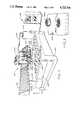
- FIG. 1Such an arrangement is diagrammatically illustrated in FIG. 1 where a workpiece 10 is on a spoil-plate 12, which in turn is positioned on the machine bed or work table 14.
- the work table 14itself is constructed with vacuum holes 16 which are connected on one end to a vacuum source through an on/off valve 18.
- the vacuum holes 16communicate with the top surface of the work table 14 so that the applied vacuum pulls the spoil-plate into tight engagement with the work table.
- the spoil-plate 12is specially designed with an undercut recess 20 and with vertical holes 22 communicating upwardly to a top recess 23.
- FIG. 1is somewhat oversimplified; in practice recess 20 and its through holes 22 must be designed to provide adequate and adequately distributed vacuum to hold the workpiece, while at the same time being coordinated to the machining program to avoid interferring with the vacuum hold down.
- a further objectis to provide such a chucking system which permits a variety of machining patterns and operations to be conveniently performed on workpieces supported by the system without damaging the cutting tool, the machine work table, or the chucking system.
- a related object of this inventionis to provide a workpiece chucking system with the above characteristics which is particularly adaptable to be programmably controlled in such a way that the entire process of supporting workpieces in a non-interfering manner with the cutting tool while subjecting the workpiece to a variety of machining patterns and operations, can be rendered automatic.
- a support systemwhich includes a spaced array of vacuum pods supported on the work table of the machine tool.
- the vacuum podshave an upper support surface which, in the normally inactivated position, is substantially flush with the work table. In the activated position the support surface is raised from the work table to provide a gap for receiving the tip of the tool.
- Each podin the preferred embodiment, has its own activator means. Means are provided to activate and thereby extend a selected subset of the array of vacuum pods. Which pods are extended depends not only on the size and shape of the workpiece, but also on the machining program, so that no pods are activated in areas through which the tool is to pass.
- a vacuum sourceis coupled to each of the activated pods to securely hold the workpiece in place.
- the selective application of pressurized air and vacuum to the support podscan be controlled manually, but preferably is controlled by action of any suitable numerical control (NC) unit conventionally used to perform programmed machining of the workpiece.
- NCnumerical control
- the NC unitis preprogrammed for a given workpiece on the basis of a known particular combination of the pods over which the workpiece will lie when positioned at a defined region of the machine tool bed. More specifically, the NC unit is provided with a part program which includes a designation of a selected subset of pods which will be active and raised while the machining of a particular workpiece or series of workpieces is being carried out.
- the designated podsare those which will be active in locations which will firmly hold the workpiece but which will not interfere with the cutting tool as it goes through the necessary motions and paths in performing the programmed machining upon the workpiece.
- This part programis used by the NC unit to send energizing signals to those particular valves associated with the program-designated subset of vacuum pods. Consequently, each selected pod has its piston arrangement pressurized so that it is raised above the machine bed surface. Energizing signals are also sent to valves associated with the designated pods in order to generate a vacuum following the placement of a workpiece upon the raised pods.
- the present inventionpermits the cutting tool to perform the desired machining operations on any of a wide variety of workpieces without damaging the cutting tool, the machine table, or the pods--and without requiring the making of a special spoil-plate or fixture for each particular workpiece.
- FIG. 1is a sectional view of a prior art technique for the elevated chucking of workpieces by using spoil-plates;
- FIG. 2is a perspective view of an exemplary milling/routing/drilling machine embodying the vacuum chucking system of this invention
- FIG. 3is an enlarged fragmentary perspective view of the work table of the machine shown in FIG. 2, showing pods in the activated and deactivated positions;
- FIG. 4is a cross-sectional view of a support pod for use with the illustrative embodiment of FIG. 2;
- FIG. 5is a top view of the support pod represented in FIG. 4;
- FIG. 6is a simplified block diagram representation of an exemplary numerical control system for the illustrative embodiment of FIG. 2;
- FIGS. 7a and 7bare schematic diagrams illustrating the connections to the various valves that regulate the functioning of the support pods.
- FIG. 8is simplified flow chart representation of the basic sequence of operations undergone by the illustrative programmable vacuum pod system.
- FIG. 2there is shown a perspective view of an exemplary milling/routing/drilling machine 100 using a vacuum pod workpiece chucking system constructed in accordance with the present invention.
- the machine 100includes a machine bed 102 which serves as an integral foundation for supporting the various components and power drives comprising the overall machining system.
- the machine bed 102carries a work table 104 which is adapted to rigidly support a workpiece 106 in order that it may be subjected to desired machining operations performed by a machining head, generally indicated at 107.
- the machining head 107is mounted on guideways 108 which defines a slide permitting sideways movement of the machining device along the Y-axis relative to the machine work table.
- the Y-axis guideways 108are carried on either end by machine uprights 110.
- the uprightsare supported on guideways 112, which permit lateral movement of the uprights 110, and hence the guideways 108 and the machining head 107, along the X-axis relative to the machine work table.
- the machining head 107includes one or more cutting tools 114 and cutting tool drives 115, mounted on supports 116 which permit vertical displacement of the cutting tools along the Z-axis relative to the machine work table 104.
- the illustrated embodimentshows the use of four power driven router spindles and three driven drilling spindles, each independently controllable.
- the milling/routing/drilling machine described so faris fairly conventional and hence the constructional and operational details need not be discussed. It suffices to state that the machine permits machining of a workpiece, rigidly supported on the work table, by the controllable independent movement of the cutting tools along the three mutually perpendicular axes X, Y and Z (as shown in FIG. 2).
- the operation of the machine illustrated in FIG. 2is typically controlled by a numerical control unit, generally indicated at 118, which is linked to the various machine components through a cable 120.
- the machine 100is provided with a plurality of vertically displaceable support pods 122 mounted in the work table 104 and lying in some preselected pattern here shown as a rectangular grid-like array.
- the pods 122are normally disposed in a substantially flush-fit manner relative to the surface of the machine work table 104 and are selectively activatable to be raised upwardly to a predefined height in order to support a workpiece placed thereupon. This is illustrated clearly in the fragmentary perspective view of FIG. 3 which shows a pod 122a in its normal retracted position and another pod 122b in its extended position relative to the work table 104.
- FIG. 4there is shown a cross-sectional view of an exemplary selectively activatable vacuum pod 122 for use with a workpiece chucking system according to the present invention.
- the pod 122comprises a substantially cylindrical body 124 defining an annular cylindrical cavity 126 in which a piston 128 is slidably disposed.
- the cylindrical pod body 124is formed with an internal upwardly projecting boss 130 which closely fits an aperture 129 in the piston 128. Stop means are provided at the end of the boss 130 for fixing the distance X by which the piston projects above the table when the pod is activated.
- such stop meansinclude a cylindrical washer 131 secured to the boss 130 and fixed in position by threaded fastener 133. Accordingly, when the piston is supplied with air pressure, the lower surface of the washer 131 sets a fixed stop for the piston 128 thereby to accurately establish the distance A that each piston projects above the surface of the work table.
- the provision of a fixed stop 131 for the piston 128is of significance. Normally all of the pods are configured exactly alike and mounted in the same fashion on the work table.
- a further cavity 132Disposed within the piston 128 is a further cavity 132, conveniently cylindrical, which is open to the upper side of the piston.
- a channel 136which projects through the threaded fastener 133 connects the internal passage 132, by way of the conduit 140 to activiator means shown as a valve 138 (V 1 ).
- the valve 138in one condition couples a source of vacuum to the chamber 132 to hold the workpiece in place, and in its opposite condition provides a source of purge air for clearing away machining debris.
- a porous screen or filter material 142is secured by means of screws 145 across the opening of the piston cavity 132.
- the cylindrical cavity 126 of the pod body 124communicates through an integral passage 143 with a conduit 144 linking the cavity to activator means in the form of a valve 146.
- the valve 146(V 2 ) is identical to the valve 138 and selectively connects the cylindrical cavity 126 either to the pressurized air source for activating the pod, or to the vacuum source for withdrawing it.
- the upper surface of the piston 128carries a first annular gasket 148 (G1) which is composed of a suitable hard rubber material and extends slightly above the upper surface of the piston to form a seat against which a workpiece 106 may rest when it comes into contact with the pod 122.
- a second annular gasket 150 (G2) of a diameter smaller than that of the gasket G1is also disposed on the upper end of the piston and normally projects upwardly from the piston surface beyond the extension of the gasket G1.
- the gasket G2is made of a relatively soft rubber material so that it forms a contact surface which is compressed by the workpiece 106 to form an airtight seal when the workpiece is placed upon the pod.
- the piston 128When a vacuum is applied to the cylindrical cavity 126 by the valve V 2 so as to connect the cavity to the vacuum source, the piston 128 will be retracted downwardly to a position in which it is substantially flush with the upper surface of the machine work table 104. This is the normal inactive position of a given pod. If the valve V 2 is switched to its alternate position, the cylindrical cavity of the pod is connected to the pressurized air source causing the piston 128 to be forced upwardly until the lower end of the cavity 132 abuts the washer 131 which, it is recalled, is secured to the upper end of the boss 130. This is the active position of the pod and in this position, the piston extends outwardly to a distance "A" above the upper surface of the machine work table. This provides a minimum clearance distance "B" between the work table 104 and a cutting tool 114 which projects completely through a workpiece 106, thereby precluding the possibility of any damaging contact between the tool and the work table.
- valve V 1When the valve V 1 is switched to couple the vacuum source to the piston cavity 132, the resulting vacuum created within the piston effectively locks the contact surface formed by the gasket G2 onto the undersurface of a workpiece placed upon the pod.
- the valve V 1connects the piston cavity 132 to the pressurized air source, air is forced through the longitudinally extending passage 136 into the piston cavity and serves to blow away any foreign particles, such as wood chips or dust, which may have accumulated on top of the filter material 142. This is referred to as "purging" of the filter material.
- the pod 122itself is rigidly anchored into position within a correspondingly sized cavity 152 formed through the machine work table 104 by means of screws 154.
- the podhas an integrally formed outwardly extending annular flange 156 defined on its external surface and the screws 154 pass through the flange 156 into the body of the machine work table 104.
- FIG. 4shows the switching of the pressurized air and the vacuum to the piston cavity and the cylindrical cavity by activator means comprising separate valves V 1 and V 2 , respectively activator means in the form of a single solenoid operated valve is used to perform this function according to one preferred aspect of the invention.
- a valvethe operation of which will be described below with reference to FIG. 7b, can conjunctively couple the cylindrical cavity of the pod and the piston cavity to either the pressurized air source or the vacuum source on the basis of the status (ON or OFF) of its solenoid.
- the action of the support podsis programmable so that the selective activation of the pods in order to support a workpiece can be performed on the basis of a predefined part program.
- This part programis exclusive to a given workpiece or series of identical workpieces and is based upon the designation of the exact region of the machine work table where a given workpiece is to be chucked into position for subsequent machining; the corresponding combination of support pods which the workpiece overlies when placed in the designated region is consequently a known factor.
- the part programdefines a selected set of support pods which are to be activated and raised while each machining operation on the given workpiece is being carried out.
- the choice of the selected set of podsis made according to the actual pattern of machining motions and operations to which the workpiece will be subjected. More specifically, the selected pods are those defined by the part program which, when in an activated position, will not be in a location that offers any interference to the cutting tool as it goes through a necessary pattern of motion to perform the programmed machining on the workpiece.
- FIG. 6there is shown a simplified block diagram representation 200 of the overall control system using the numerical control unit to programmably regulate the operation of the illustrative workpiece chucking system.
- the systemis controlled by a conventional numerical control unit which comprises a control processor 202, the internal configuration and processing action of which is well known in the art and is hence not described here.
- a CRT 204is dedicated for remote display of input, intermediate and output data, as well as other related information and communications. Part programs for the chucking system and related data may be manually input to the numerical control by a keyboard 206.
- the control processorsends the appropriate signals to the machine axis servos represented at 212 to control the actual cutting sequences and operations.
- the control processor 202acts upon part program data taken from any suitable memory 213 which functions basically to store the part programs for one or more different workpieces. Each part program may contain instructions for the sub-set of pods 122 which are to be activated when the corresponding workpiece is being treated.
- a suitable multiplexer 214is connected to valves 216 (V 1 , V 2 , V 3 . . . V n ) respectively associated with the pods 122 disposed upon the machine work table.
- the numerical controlregulates the action of the valves 216 in such a way that the vacuum source 220 and the pressurized air source 222 are connected to selected support pods 122 according to the part program fed to the numerical control at the start of a machining cycle. It will be obvious that, once a series of part programs corresponding to a series of different workpieces is prepared and stored within the numerical controller, the illustrative chucking system can be conveniently adapted to be used with the different workpieces by simply extracting the part program corresponding to a given workpiece from the numerical controller's memory and using that as a basis for controlling the action of the valves associated with the respective support pods.
- FIGS. 7a and 7bthere is shown a schematic diagram illustrating the connections to the various valves that control the action of the support pods.
- individual activator for the podsin the form of valves 216 (V 1 , V 2 . . . V n ) are arranged together within one or more valve manifold assemblies 302.
- Each of the valves 216is a conventional solenoid actuated valve configured in such a way that it accepts three input lines: (i) E V (vacuum) coming in from the vacuum source, (ii) E A (activating air) coming in from the pressurized air source and (iii) E P (purge air) also coming in from the pressurized air source.
- a given valve 216connects selected ones of the three input lines to two output lines leading out to (i) the piston cavity 132 in the corresponding pod, and (ii) the cylindrical cavity 126 in the corresponding pod. More specifically, the valve connections are made in such a way that when the solenoid S P is switched off (and the connections represented in the left half of FIG. 7b are in effect), the pod is retracted and the pod filter is purged. In other words, when S P is OFF, the regulating valve connects the cylinder cavity 132 to the vacuum source line E V whereby the applied vacuum pulls the pod piston down to its normally retracted position. Also, the piston cavity is connected to the purge line E P so that a pulse of pressurized air is blown through the filter material to purge it.
- valves 216 and hence the operation of the support podare provided by the inclusion of a pair of control valves between the valve manifold connections and the vacuum and pressurized air sources. More specifically, a pneumatic solenoid valve 304 whose action is controlled by the status of a solenoid S 1 , connects the common purge line E P from the valve manifold 302 to the pressurized air source. A second pneumatic solenoid valve 306, whose action is controlled by the status of a solenoid S 2 , connects the common vacuum line E V from the valve manifold to the vacuum source.
- the valve 306is also connected to a vacuum gauge 308 providing a measure of the vacuum pressure applied by the vacuum source, and a master vacuum switch 310 for activating or deactivating the vacuum source.
- the common pressurized air line E A from the valve manifoldis connected to the pressurized air source through an air regulator/gauge mechanism 312 which allows adjustment of air pressure and an indication of the air pressure.
- the master valves 304 and 306are controlled in combination in order to achieve desired operation of selected valves within the valve manifold and hence the corresponding support pods. Normally, when the machine tool is inactive, both valves 304 and 306 are off so that neither purge air nor vacuum are supplied to the vacuum pods by way of the valve manifold 302. The main pressure source, however, is not switched such that activation air is supplied to the valve manifold, but all the valves 216 are off so that all pods remain deactivated.
- the vacuum valve 306Prior to commencement of a machining cycle, but after the workpiece is accurately located on the work table, the vacuum valve 306 is switched on so that the vacuum source is applied to the valves 300 associated with all of the pods. A selected subset of the solenoids S p is activated which has two effects. The air supply E A to the selected pods is applied to the cylinders of the selected pods causing them to rise. At the same time, the vacuum source E V is applied to the internal cavities 132 of the selected pods, thereby drawing the workpiece thereto. Thus, the workpiece is firmly held in place and raised from the machine table so that machining operations can be performed. As described previously, individual ones of the valves 216 can be activated or deactivated during the course of machining to firmly support the workpiece, but to be retracted when the machining operation brings an active tool into the location occupied by that particular pod.
- the individual valves 216can be deactivated which switches off the vacuum to each of the activated pods, switches off the activating air to each of the pods, and furthermore applies vacuum within the pod cylinder to retract the pod.
- the workpiececan then be removed.
- the valve 304can be momentarily activated to blow a pulse of purge air through the filters, thus clearing the pods in preparation for receipt of the next workpiece.
- the podsneed not be withdrawn to remove the workpiece. It is simply necessary to deactivate the valve 306 which removes the vacuum source from within the pods so that the workpiece can be removed. In that mode of operation, the valve 304 can also be momentarily activated to purge the pods before the next workpiece is positioned for machining.
- the activation of a certain set of solenoids S pis defined, for a given workpiece or a series of workpieces, by the specially written part program which clearly specifies which particular subset of valves has to be activated at any given time during the machining of a particular workpiece.
- the subset of support pods specified in a part programare selected on the basis of the desired pattern of machining operations to be performed on a particular workpiece and represent those pods which in combination are capable of adequately supporting the workpiece while it is being machined without interfering with the cutting tool as it traces the path required to machine the workpiece.
- the part programdefines the operation of the valves under the assumption that the pressurized air source and the vacuum source are continuously connected to the valves.
- the master valves 304, 306provide a means of additional control over the support pod action by controlling the actual connection of the air and vacuum sources to the valve manifold assembly. It will however be understood that the master valves are not essential to the operation of the illustrative chucking system which can operate efficiently just by the programmed operation of the valves on the basis of the predefined part program.
- the initial step 400involves the definition of a part program for the particular workpiece that is to be machined. This program is then either keyed into the numerical controller unit of the machining system or transferred to the NC unit through its disk drive.
- all support podsare retracted to their normal flush-fit position relative to the work table by the application of a vacuum to the cylindrical cavity of the pod.
- the NC unitinitiates the part program stored within it.
- the machinistpositions the workpiece on the work table. Conveniently, stops are positioned on the work table for accurate location of the workpiece.
- the NC unitactivates the subset of support pods specified by the part program at a step 408.
- the workis thereupon locked in position and supported above the work table so that step 412 can be accomplished to machine the part.
- podscan be raised or lowered as needed as the machining proceeds.
- the podsare deactivated at step 418 by releasing the activating air, removing the vacuum from the hold down cylinders and applying vacuum to the internal cylinders to withdrawn the pods.
- the workpieceis removed at step 420 following which purge air is momentarily activated at step 422 to clear the machine table for positioning of a new part.
- Step 424illustrates that the work cycle has thereupon been completed.
- the above sequence of operationhas been described only by way of illustration and not by way of limitation.
- the sequence of operations involved in the chucking of workpiecesmay be changed to suit particular machining operations.
- the podsmay be left in the activated position while the workpiece is changed.
- the selected subset of podsis activated continuously by way of the valves 300.
- the vacuum valve 306is energized so that all of the activated pods receive vacuum in the hold down chamber to hold the workpiece in place.
- the vacuum valve 306is deactivated to release the workpiece although the individual pod valves 300 remain activated and thus remain in the raised position. Purge air can be supplied as needed.
- the illustrative workpiece chucking systemis not restricted for use with workpieces having completely flat undersurfaces.
- the systemcan function efficiently as long as the undersurface of the workpiece has a plurality of well-defined flat areas with which a particular set of support pods selected by an appropriate part program may make contact in order to adequately support the workpiece in an elevated manner.
- the programmable vacuum support pod workpiece chucking system of this inventionprovides a higher flexible system for supporting any given one of a plurality of workpieces, having of different shapes and contours, in a manner that permits interference-free machining--and without the need for any special fixtures such as spoil-plates.
Landscapes
- Engineering & Computer Science (AREA)
- Mechanical Engineering (AREA)
- Jigs For Machine Tools (AREA)
Abstract
Description
Claims (9)
Priority Applications (1)
| Application Number | Priority Date | Filing Date | Title |
|---|---|---|---|
| US06/913,980US4723766A (en) | 1986-10-01 | 1986-10-01 | Programmable vacuum pod system for chucking workpieces |
Applications Claiming Priority (1)
| Application Number | Priority Date | Filing Date | Title |
|---|---|---|---|
| US06/913,980US4723766A (en) | 1986-10-01 | 1986-10-01 | Programmable vacuum pod system for chucking workpieces |
Publications (1)
| Publication Number | Publication Date |
|---|---|
| US4723766Atrue US4723766A (en) | 1988-02-09 |
Family
ID=25433778
Family Applications (1)
| Application Number | Title | Priority Date | Filing Date |
|---|---|---|---|
| US06/913,980Expired - LifetimeUS4723766A (en) | 1986-10-01 | 1986-10-01 | Programmable vacuum pod system for chucking workpieces |
Country Status (1)
| Country | Link |
|---|---|
| US (1) | US4723766A (en) |
Cited By (69)
| Publication number | Priority date | Publication date | Assignee | Title |
|---|---|---|---|---|
| US4805887A (en)* | 1987-11-12 | 1989-02-21 | Rayco Manufacturing, Inc. | Universal vacuum and clamp setup fixture for coordinate measuring machines |
| US4880218A (en)* | 1987-12-03 | 1989-11-14 | Steelcase Inc. | Programmable bed for machine tools and the like |
| US4946149A (en)* | 1987-12-03 | 1990-08-07 | Steelcase, Inc. | Programmable bed for machine tools and the like |
| EP0425127A3 (en)* | 1989-10-27 | 1991-10-02 | Hughes Aircraft Company | Improved vibration testing system |
| USD323628S (en) | 1989-04-25 | 1992-02-04 | Tokyo Electron Limited | Semiconductor wafer measuring instrument |
| EP0473954A1 (en)* | 1990-09-07 | 1992-03-11 | DATRON-ELECTRONIC GmbH | Clamping device for workpieces |
| US5120033A (en)* | 1990-07-03 | 1992-06-09 | Isao Shoda | Work table for wood working machine or the like |
| FR2670148A1 (en)* | 1990-12-11 | 1992-06-12 | Aerospatiale | DEVICE FOR CONFORMING AND MAINTAINING THIN PIECES OF LARGE DIMENSIONS TO A PREDETERMINED THEORETICAL PROFILE. |
| WO1992010336A3 (en)* | 1990-12-08 | 1992-07-23 | Carne Ufm Ltd | Vaccum plates |
| US5135120A (en)* | 1991-01-11 | 1992-08-04 | Rayco Manufacturing, Inc. | Multi-fixture rack system |
| US5141212A (en)* | 1991-04-08 | 1992-08-25 | Ekstrom Carlson & Co. | Vacuum chuck with foam workpiece-supporting surface |
| EP0537674A1 (en)* | 1991-10-17 | 1993-04-21 | Wolfgang Mayer | Device for cutting out and machining edges of flat workpieces |
| US5222719A (en)* | 1992-02-18 | 1993-06-29 | Jamesway Products & Services Inc. | Means for holding workpiece for machining |
| US5249785A (en)* | 1992-04-20 | 1993-10-05 | Boeing Commercial Airplane Group | Reconfigurable holding fixture |
| EP0566770A1 (en)* | 1992-04-24 | 1993-10-27 | Homag Maschinenbau Ag | Method and device dividing a panel and machining the parts |
| DE4215140A1 (en)* | 1992-05-08 | 1993-11-11 | Georg Geis Maschinenfabrik | Suction gripping worktable for milling machine - has multiple suction gripping elements arranged in plane of worktable |
| DE4221222A1 (en)* | 1992-06-27 | 1994-01-05 | Ottensteiner Kunststoff Gmbh | Vacuum suction device for holding work objects - consists of support panel for objects perforated by vertical holes surrounded by sealing strip with another sealing strip on its underside |
| EP0604339A1 (en)* | 1992-12-24 | 1994-06-29 | Christophe Boiteaux | Articulated means for wedging |
| US5364083A (en)* | 1992-07-15 | 1994-11-15 | The Boeing Company | Universal holding fixture end effector |
| US5372357A (en)* | 1991-03-26 | 1994-12-13 | Gfm Gesellschaft Fur Fertigungstechnik Und Maschinenbau Aktiengesellschaft | Work-supporting deck for use in machine tools, particularly in cutting machines |
| US5409334A (en)* | 1994-03-16 | 1995-04-25 | David Edis | Vacuum vice for bowling balls |
| US5414617A (en)* | 1993-09-21 | 1995-05-09 | Gerber Garment Technology, Inc. | Controlled zone vacuum system |
| US5457868A (en)* | 1991-03-26 | 1995-10-17 | Gfm Gesellschaft Fur Fertigungstechnik Und Maschinenbau Aktiengesellschaft | Work supporting method using a deck for use in machine tools, particularly in cutting machines |
| EP0678357A1 (en)* | 1994-04-19 | 1995-10-25 | Smartech Llc | Membrane press and method of elevating a workpiece |
| WO1996033049A1 (en)* | 1995-04-19 | 1996-10-24 | Kimble Alvin J | Locking ring vacuum clamping system with load/unload capabilities |
| DE19526138A1 (en)* | 1995-07-18 | 1997-01-23 | Buerkle Gmbh & Co Robert | Support system for use in veneering board-shaped workpieces |
| DE19530584C1 (en)* | 1995-08-19 | 1997-02-13 | Karl Goeckel | Workpiece support table with a vacuum suction device for workpiece fixation |
| US5634749A (en)* | 1994-03-16 | 1997-06-03 | Jerry Liem | Vacuum vice for bowling balls |
| EP0744280A3 (en)* | 1995-05-23 | 1997-09-10 | Smartech Llc | Membrane press, work base, and method of elevating a three-dimensional workpiece |
| DE19631661A1 (en)* | 1996-08-05 | 1998-02-12 | Homag Maschinenbau Ag | Processing machine |
| US5735512A (en)* | 1995-08-11 | 1998-04-07 | Northwest Product Development, L.L.C. | Portable leveling vacuum tool |
| US5743685A (en)* | 1994-06-02 | 1998-04-28 | Quickmill, Inc. | Clamping device for a workpiece processing machine |
| DE19718561A1 (en)* | 1997-05-02 | 1998-11-05 | Buerkle Gmbh Robert | Method and device for processing workpieces, in particular for coating |
| US5837901A (en)* | 1996-03-05 | 1998-11-17 | Dea-Brown & Sharpe S.P.A. | Reconfigurable supporting fixture, particularly for a measuring machine, and relative configuration method |
| FR2763877A1 (en)* | 1997-05-30 | 1998-12-04 | Itb | DEVICE FOR FIXING A FLAT PART BY AIR DEPRESSION OF THE VACUUM TABLE TYPE FOR A MACHINING CENTER |
| US5853169A (en)* | 1995-10-24 | 1998-12-29 | O'sullivan Industries | Vacuum pod support system |
| US5880774A (en)* | 1992-04-28 | 1999-03-09 | Texas Instruments Incorporated | Non-invasive inspection platen |
| US5887733A (en)* | 1996-04-19 | 1999-03-30 | Omni Structures International, Inc. | Modular tower tooling system |
| US5899445A (en)* | 1996-04-18 | 1999-05-04 | Kimble; Alvin J. | Locking ring vacuum clamping system with load/unload capabilities |
| WO1999061206A1 (en)* | 1998-05-28 | 1999-12-02 | Heian Europe S.R.L. | Vacuum locking system for panels to be worked |
| US6032348A (en)* | 1998-03-20 | 2000-03-07 | Northrop Grumman Corporation | Method of forming a modularized adjustable holding fixture |
| US6042095A (en)* | 1998-07-15 | 2000-03-28 | Gerber Technology, Inc. | Method and apparatus for retaining one or more layers of sheet type work material on a support surface |
| US6089801A (en)* | 1998-07-01 | 2000-07-18 | Thermwood Corporation | Machine tool with improved workpiece holddown system |
| US6099215A (en)* | 1994-06-02 | 2000-08-08 | Quickmill Inc. | Clamping device |
| US6129027A (en)* | 1996-08-05 | 2000-10-10 | Shomag Maschinenbau Ag | Processing machine |
| US6182955B1 (en)* | 1998-07-03 | 2001-02-06 | Alvin Jay Kimble | Grid-lock vacuum clamping system |
| US6202275B1 (en)* | 1997-12-12 | 2001-03-20 | Maglev, Inc. | Precision assembly table and method |
| WO2001078947A1 (en)* | 2000-04-14 | 2001-10-25 | Multiax Srl | Retaining means build by suction cups in a machine for the manufacture of panels |
| US6386805B1 (en)* | 1999-12-20 | 2002-05-14 | Heian Corporation | Suction table apparatus for a numerical control machine |
| FR2829721A1 (en)* | 2001-09-18 | 2003-03-21 | Alexandre Udin | Three dimensional curved panel manufacturing apparatus comprises forming impression comprising membrane and series of selective deforming members |
| WO2003024688A1 (en)* | 2001-09-18 | 2003-03-27 | Sail Innovation | Device for making panels with three-dimensional curvature from sheet material, for example for thermoforming sails from thermoplastic material and resulting single-piece sail |
| US6561249B2 (en)* | 2000-07-10 | 2003-05-13 | Robert Burkle Gmbh | Press device for coating workpieces, especially pieces of furniture, on multiple sides |
| US6607336B1 (en)* | 1999-10-05 | 2003-08-19 | Heian Corporation | Suction table apparatus for a numerical control machine |
| US20070161331A1 (en)* | 2005-11-10 | 2007-07-12 | John Nelson | Stone fabrication positioning system |
| US20070262494A1 (en)* | 2006-05-12 | 2007-11-15 | Edwin Oakey | Apparatus for a mold vacuum system and method of forming a sheet metal utilizing the system |
| CN100391696C (en)* | 2005-09-15 | 2008-06-04 | 江南大学 | Adaptive Vacuum Suction Table |
| US20090173723A1 (en)* | 2006-12-22 | 2009-07-09 | Yoshinori Nakagawa | Laser processing apparatus and laser processing method using the same technical field |
| US7669839B2 (en) | 2006-07-10 | 2010-03-02 | Mcclaran Michael Lloyd | Vacuum hold down |
| US20100156014A1 (en)* | 2006-07-10 | 2010-06-24 | Mcclaran Michael | Multi-Seal Vacuum Hold Down |
| US20110049778A1 (en)* | 2009-09-02 | 2011-03-03 | Gm Global Technology Operations, Inc. | Flexible fixture system for machining operations |
| US20130149077A1 (en)* | 2011-12-13 | 2013-06-13 | Intermolecular, Inc. | Method and apparatus for controlling force between reactor and substrate |
| DE102008038257B4 (en)* | 2008-08-11 | 2013-10-10 | J. Schmalz Gmbh | Vacuum clamping device with slip-resistant and movable brake element |
| US20150357217A1 (en)* | 2012-12-28 | 2015-12-10 | Shanghai Micro Electronics Equipment Co,, Ltd | Warped silicon-chip adsorption device and adsorption method thereof |
| US9533384B1 (en) | 2012-03-29 | 2017-01-03 | Norgren Automation Solutions, Llc | Method and apparatus for accurately positioning automated modular tooling |
| CN107649783A (en)* | 2017-09-30 | 2018-02-02 | 苏州安靠电源有限公司 | Battery modules weld charging positioning device |
| CN109689283A (en)* | 2016-09-07 | 2019-04-26 | 豪迈钻孔装置有限公司 | Variable machine table |
| IT202000016294A1 (en)* | 2020-07-06 | 2022-01-06 | Dario Toncelli | WORKING GROUP FOR MAKING HOLES IN A SHEET MATERIAL AND FOR PROCESSING THE INNER EDGE OF THE HOLES AND MACHINE TOOL COMPRISING THIS WORKING GROUP |
| USD968199S1 (en) | 2019-04-23 | 2022-11-01 | Hk Marketing Lc | Tie standoff |
| US11583965B2 (en) | 2018-04-12 | 2023-02-21 | Advanced Machine Works, LLC | Static flexible tooling system |
Citations (10)
| Publication number | Priority date | Publication date | Assignee | Title |
|---|---|---|---|---|
| US2680994A (en)* | 1951-10-22 | 1954-06-15 | Boeing Co | Suction holding device |
| US3272611A (en)* | 1962-02-28 | 1966-09-13 | Pittsburgh Plate Glass Co | Apparatus for making multiple glazed units |
| US3460822A (en)* | 1965-10-23 | 1969-08-12 | E & E Eng Co | Vacuum workholder |
| US3484093A (en)* | 1967-07-03 | 1969-12-16 | Sylvania Electric Prod | Article holding apparatus |
| US3596429A (en)* | 1968-07-26 | 1971-08-03 | Clarence W Vogt | Apparatus and method for filling flexible containers |
| US3729206A (en)* | 1971-10-21 | 1973-04-24 | Ibm | Vacuum holding apparatus |
| US3838865A (en)* | 1973-08-24 | 1974-10-01 | Atomic Energy Commission | Fixture for supporting a workpiece in a machine tool |
| US3957263A (en)* | 1972-03-29 | 1976-05-18 | J. Bobst & Fils S.A. | Telescopic suction member for feeding sheet material |
| US4088312A (en)* | 1977-09-27 | 1978-05-09 | Nasa | Variable contour securing system |
| US4391511A (en)* | 1980-03-19 | 1983-07-05 | Hitachi, Ltd. | Light exposure device and method |
- 1986
- 1986-10-01USUS06/913,980patent/US4723766A/ennot_activeExpired - Lifetime
Patent Citations (10)
| Publication number | Priority date | Publication date | Assignee | Title |
|---|---|---|---|---|
| US2680994A (en)* | 1951-10-22 | 1954-06-15 | Boeing Co | Suction holding device |
| US3272611A (en)* | 1962-02-28 | 1966-09-13 | Pittsburgh Plate Glass Co | Apparatus for making multiple glazed units |
| US3460822A (en)* | 1965-10-23 | 1969-08-12 | E & E Eng Co | Vacuum workholder |
| US3484093A (en)* | 1967-07-03 | 1969-12-16 | Sylvania Electric Prod | Article holding apparatus |
| US3596429A (en)* | 1968-07-26 | 1971-08-03 | Clarence W Vogt | Apparatus and method for filling flexible containers |
| US3729206A (en)* | 1971-10-21 | 1973-04-24 | Ibm | Vacuum holding apparatus |
| US3957263A (en)* | 1972-03-29 | 1976-05-18 | J. Bobst & Fils S.A. | Telescopic suction member for feeding sheet material |
| US3838865A (en)* | 1973-08-24 | 1974-10-01 | Atomic Energy Commission | Fixture for supporting a workpiece in a machine tool |
| US4088312A (en)* | 1977-09-27 | 1978-05-09 | Nasa | Variable contour securing system |
| US4391511A (en)* | 1980-03-19 | 1983-07-05 | Hitachi, Ltd. | Light exposure device and method |
Cited By (88)
| Publication number | Priority date | Publication date | Assignee | Title |
|---|---|---|---|---|
| US4805887A (en)* | 1987-11-12 | 1989-02-21 | Rayco Manufacturing, Inc. | Universal vacuum and clamp setup fixture for coordinate measuring machines |
| US4880218A (en)* | 1987-12-03 | 1989-11-14 | Steelcase Inc. | Programmable bed for machine tools and the like |
| US4946149A (en)* | 1987-12-03 | 1990-08-07 | Steelcase, Inc. | Programmable bed for machine tools and the like |
| USD323628S (en) | 1989-04-25 | 1992-02-04 | Tokyo Electron Limited | Semiconductor wafer measuring instrument |
| EP0425127A3 (en)* | 1989-10-27 | 1991-10-02 | Hughes Aircraft Company | Improved vibration testing system |
| US5120033A (en)* | 1990-07-03 | 1992-06-09 | Isao Shoda | Work table for wood working machine or the like |
| EP0473954A1 (en)* | 1990-09-07 | 1992-03-11 | DATRON-ELECTRONIC GmbH | Clamping device for workpieces |
| WO1992010336A3 (en)* | 1990-12-08 | 1992-07-23 | Carne Ufm Ltd | Vaccum plates |
| FR2670148A1 (en)* | 1990-12-11 | 1992-06-12 | Aerospatiale | DEVICE FOR CONFORMING AND MAINTAINING THIN PIECES OF LARGE DIMENSIONS TO A PREDETERMINED THEORETICAL PROFILE. |
| EP0490746A1 (en)* | 1990-12-11 | 1992-06-17 | AEROSPATIALE Société Nationale Industrielle | Process and apparatus for shaping and clamping thin workpieces of large dimensions in a predetermined calculated profile |
| US5135120A (en)* | 1991-01-11 | 1992-08-04 | Rayco Manufacturing, Inc. | Multi-fixture rack system |
| US5372357A (en)* | 1991-03-26 | 1994-12-13 | Gfm Gesellschaft Fur Fertigungstechnik Und Maschinenbau Aktiengesellschaft | Work-supporting deck for use in machine tools, particularly in cutting machines |
| US5457868A (en)* | 1991-03-26 | 1995-10-17 | Gfm Gesellschaft Fur Fertigungstechnik Und Maschinenbau Aktiengesellschaft | Work supporting method using a deck for use in machine tools, particularly in cutting machines |
| US5141212A (en)* | 1991-04-08 | 1992-08-25 | Ekstrom Carlson & Co. | Vacuum chuck with foam workpiece-supporting surface |
| EP0537674A1 (en)* | 1991-10-17 | 1993-04-21 | Wolfgang Mayer | Device for cutting out and machining edges of flat workpieces |
| US5318005A (en)* | 1991-10-17 | 1994-06-07 | Wolfgang Mayer | Apparatus for cutting plate-shaped workpieces and for edge processing thereof |
| DE4134273A1 (en)* | 1991-10-17 | 1993-04-22 | Wolfgang Mayer | DEVICE FOR CUTTING AND EDGE PROCESSING OF PANEL-SHAPED WORKPIECES |
| US5222719A (en)* | 1992-02-18 | 1993-06-29 | Jamesway Products & Services Inc. | Means for holding workpiece for machining |
| US5249785A (en)* | 1992-04-20 | 1993-10-05 | Boeing Commercial Airplane Group | Reconfigurable holding fixture |
| EP0566770A1 (en)* | 1992-04-24 | 1993-10-27 | Homag Maschinenbau Ag | Method and device dividing a panel and machining the parts |
| US5880774A (en)* | 1992-04-28 | 1999-03-09 | Texas Instruments Incorporated | Non-invasive inspection platen |
| DE4215140A1 (en)* | 1992-05-08 | 1993-11-11 | Georg Geis Maschinenfabrik | Suction gripping worktable for milling machine - has multiple suction gripping elements arranged in plane of worktable |
| DE4221222A1 (en)* | 1992-06-27 | 1994-01-05 | Ottensteiner Kunststoff Gmbh | Vacuum suction device for holding work objects - consists of support panel for objects perforated by vertical holes surrounded by sealing strip with another sealing strip on its underside |
| US5364083A (en)* | 1992-07-15 | 1994-11-15 | The Boeing Company | Universal holding fixture end effector |
| EP0604339A1 (en)* | 1992-12-24 | 1994-06-29 | Christophe Boiteaux | Articulated means for wedging |
| FR2699846A1 (en)* | 1992-12-24 | 1994-07-01 | Boiteux Christophe | Articulated wedging element. |
| US5414617A (en)* | 1993-09-21 | 1995-05-09 | Gerber Garment Technology, Inc. | Controlled zone vacuum system |
| US5409334A (en)* | 1994-03-16 | 1995-04-25 | David Edis | Vacuum vice for bowling balls |
| US5607268A (en)* | 1994-03-16 | 1997-03-04 | Jerry Liem | Vacuum vice for bowling balls and method |
| US5634749A (en)* | 1994-03-16 | 1997-06-03 | Jerry Liem | Vacuum vice for bowling balls |
| EP0678357A1 (en)* | 1994-04-19 | 1995-10-25 | Smartech Llc | Membrane press and method of elevating a workpiece |
| US6099215A (en)* | 1994-06-02 | 2000-08-08 | Quickmill Inc. | Clamping device |
| US5743685A (en)* | 1994-06-02 | 1998-04-28 | Quickmill, Inc. | Clamping device for a workpiece processing machine |
| WO1996033049A1 (en)* | 1995-04-19 | 1996-10-24 | Kimble Alvin J | Locking ring vacuum clamping system with load/unload capabilities |
| EP0744280A3 (en)* | 1995-05-23 | 1997-09-10 | Smartech Llc | Membrane press, work base, and method of elevating a three-dimensional workpiece |
| DE19526138A1 (en)* | 1995-07-18 | 1997-01-23 | Buerkle Gmbh & Co Robert | Support system for use in veneering board-shaped workpieces |
| US5735512A (en)* | 1995-08-11 | 1998-04-07 | Northwest Product Development, L.L.C. | Portable leveling vacuum tool |
| DE19530584C1 (en)* | 1995-08-19 | 1997-02-13 | Karl Goeckel | Workpiece support table with a vacuum suction device for workpiece fixation |
| US5853169A (en)* | 1995-10-24 | 1998-12-29 | O'sullivan Industries | Vacuum pod support system |
| US5837901A (en)* | 1996-03-05 | 1998-11-17 | Dea-Brown & Sharpe S.P.A. | Reconfigurable supporting fixture, particularly for a measuring machine, and relative configuration method |
| US5899445A (en)* | 1996-04-18 | 1999-05-04 | Kimble; Alvin J. | Locking ring vacuum clamping system with load/unload capabilities |
| US5887733A (en)* | 1996-04-19 | 1999-03-30 | Omni Structures International, Inc. | Modular tower tooling system |
| DE19631661A1 (en)* | 1996-08-05 | 1998-02-12 | Homag Maschinenbau Ag | Processing machine |
| DE19631661C2 (en)* | 1996-08-05 | 2000-05-25 | Homag Maschinenbau Ag | Processing machine |
| US6129027A (en)* | 1996-08-05 | 2000-10-10 | Shomag Maschinenbau Ag | Processing machine |
| DE19718561A1 (en)* | 1997-05-02 | 1998-11-05 | Buerkle Gmbh Robert | Method and device for processing workpieces, in particular for coating |
| FR2763877A1 (en)* | 1997-05-30 | 1998-12-04 | Itb | DEVICE FOR FIXING A FLAT PART BY AIR DEPRESSION OF THE VACUUM TABLE TYPE FOR A MACHINING CENTER |
| US6453544B2 (en) | 1997-12-12 | 2002-09-24 | Maglev, Inc. | Precision assembly table and method |
| US6202275B1 (en)* | 1997-12-12 | 2001-03-20 | Maglev, Inc. | Precision assembly table and method |
| US6032348A (en)* | 1998-03-20 | 2000-03-07 | Northrop Grumman Corporation | Method of forming a modularized adjustable holding fixture |
| WO1999061206A1 (en)* | 1998-05-28 | 1999-12-02 | Heian Europe S.R.L. | Vacuum locking system for panels to be worked |
| US6089801A (en)* | 1998-07-01 | 2000-07-18 | Thermwood Corporation | Machine tool with improved workpiece holddown system |
| US6182955B1 (en)* | 1998-07-03 | 2001-02-06 | Alvin Jay Kimble | Grid-lock vacuum clamping system |
| US6042095A (en)* | 1998-07-15 | 2000-03-28 | Gerber Technology, Inc. | Method and apparatus for retaining one or more layers of sheet type work material on a support surface |
| US6607336B1 (en)* | 1999-10-05 | 2003-08-19 | Heian Corporation | Suction table apparatus for a numerical control machine |
| US6386805B1 (en)* | 1999-12-20 | 2002-05-14 | Heian Corporation | Suction table apparatus for a numerical control machine |
| WO2001078947A1 (en)* | 2000-04-14 | 2001-10-25 | Multiax Srl | Retaining means build by suction cups in a machine for the manufacture of panels |
| US6561249B2 (en)* | 2000-07-10 | 2003-05-13 | Robert Burkle Gmbh | Press device for coating workpieces, especially pieces of furniture, on multiple sides |
| WO2003024688A1 (en)* | 2001-09-18 | 2003-03-27 | Sail Innovation | Device for making panels with three-dimensional curvature from sheet material, for example for thermoforming sails from thermoplastic material and resulting single-piece sail |
| WO2003024687A1 (en)* | 2001-09-18 | 2003-03-27 | Sas Sail Innovation | Device for making panels with three-dimensional curvature from sheet material, for example for thermoforming sails from thermoplastic material, and resulting single-piece sail |
| FR2829721A1 (en)* | 2001-09-18 | 2003-03-21 | Alexandre Udin | Three dimensional curved panel manufacturing apparatus comprises forming impression comprising membrane and series of selective deforming members |
| US20050064148A1 (en)* | 2001-09-18 | 2005-03-24 | Alexandre Udin | Device for making panels with three-dimensional curvature from sheet material, for example for thermoforming sails from thermo-plastic material and resulting single-piece sail |
| US7462321B2 (en) | 2001-09-18 | 2008-12-09 | Sail Innovation | Process for thermorming a three-dimensionally curved panel |
| CN100391696C (en)* | 2005-09-15 | 2008-06-04 | 江南大学 | Adaptive Vacuum Suction Table |
| US20070161331A1 (en)* | 2005-11-10 | 2007-07-12 | John Nelson | Stone fabrication positioning system |
| US20070262494A1 (en)* | 2006-05-12 | 2007-11-15 | Edwin Oakey | Apparatus for a mold vacuum system and method of forming a sheet metal utilizing the system |
| US8894912B2 (en) | 2006-05-12 | 2014-11-25 | Edwin J. Oakey | Apparatus for a mold vacuum system and method of forming a polymeric sheet utilizing the system |
| US8251688B2 (en)* | 2006-05-12 | 2012-08-28 | PH Realty, Inc. | Apparatus for a mold vacuum system and method of forming a sheet utilizing the system |
| US20100156014A1 (en)* | 2006-07-10 | 2010-06-24 | Mcclaran Michael | Multi-Seal Vacuum Hold Down |
| US7669839B2 (en) | 2006-07-10 | 2010-03-02 | Mcclaran Michael Lloyd | Vacuum hold down |
| US8322696B2 (en) | 2006-07-10 | 2012-12-04 | Mcclaran Michael | Multi-seal vacuum hold down |
| US20090173723A1 (en)* | 2006-12-22 | 2009-07-09 | Yoshinori Nakagawa | Laser processing apparatus and laser processing method using the same technical field |
| US9421638B2 (en)* | 2006-12-22 | 2016-08-23 | Panasonic Intellectual Property Management Co., Ltd. | Laser processing apparatus and laser processing method using the same technical field |
| DE102008038257B4 (en)* | 2008-08-11 | 2013-10-10 | J. Schmalz Gmbh | Vacuum clamping device with slip-resistant and movable brake element |
| US8424858B2 (en)* | 2009-09-02 | 2013-04-23 | GM Global Technology Operations LLC | Flexible fixture system for machining operations |
| US20110049778A1 (en)* | 2009-09-02 | 2011-03-03 | Gm Global Technology Operations, Inc. | Flexible fixture system for machining operations |
| US20130149077A1 (en)* | 2011-12-13 | 2013-06-13 | Intermolecular, Inc. | Method and apparatus for controlling force between reactor and substrate |
| US8807550B2 (en)* | 2011-12-13 | 2014-08-19 | Intermolecular, Inc. | Method and apparatus for controlling force between reactor and substrate |
| US9533384B1 (en) | 2012-03-29 | 2017-01-03 | Norgren Automation Solutions, Llc | Method and apparatus for accurately positioning automated modular tooling |
| US20150357217A1 (en)* | 2012-12-28 | 2015-12-10 | Shanghai Micro Electronics Equipment Co,, Ltd | Warped silicon-chip adsorption device and adsorption method thereof |
| CN109689283A (en)* | 2016-09-07 | 2019-04-26 | 豪迈钻孔装置有限公司 | Variable machine table |
| CN107649783A (en)* | 2017-09-30 | 2018-02-02 | 苏州安靠电源有限公司 | Battery modules weld charging positioning device |
| US11583965B2 (en) | 2018-04-12 | 2023-02-21 | Advanced Machine Works, LLC | Static flexible tooling system |
| US11945064B2 (en) | 2018-04-12 | 2024-04-02 | Advanced Machine Works, LLC | Static flexible tooling system |
| USD968199S1 (en) | 2019-04-23 | 2022-11-01 | Hk Marketing Lc | Tie standoff |
| USD1061227S1 (en) | 2019-04-23 | 2025-02-11 | Hk Marketing Lc | Tie standoff |
| IT202000016294A1 (en)* | 2020-07-06 | 2022-01-06 | Dario Toncelli | WORKING GROUP FOR MAKING HOLES IN A SHEET MATERIAL AND FOR PROCESSING THE INNER EDGE OF THE HOLES AND MACHINE TOOL COMPRISING THIS WORKING GROUP |
| WO2022009021A3 (en)* | 2020-07-06 | 2022-02-17 | Dario Toncelli | Working unit for realizing holes in a slab material and for machining the inner side of the holes and machine tool comprising such working unit |
Similar Documents
| Publication | Publication Date | Title |
|---|---|---|
| US4723766A (en) | Programmable vacuum pod system for chucking workpieces | |
| US6209188B1 (en) | Flexible tooling method | |
| US5899445A (en) | Locking ring vacuum clamping system with load/unload capabilities | |
| US5364083A (en) | Universal holding fixture end effector | |
| US5906378A (en) | Coupling adapter | |
| US4641819A (en) | Flexible assembly jig | |
| US6457919B1 (en) | Multi-purpose machine tool for high volume secondary operations | |
| US6328507B1 (en) | Working table apparatus for a cutting machine tool | |
| JPS5988202A (en) | Duplex system slide type multiple spindle machine | |
| EP0093575B1 (en) | A method of operating a machine tool | |
| EP0603438B1 (en) | Suction tables for a numerical control router | |
| US6419216B1 (en) | Workpiece holddown system for machine tools | |
| US6572091B2 (en) | Magnetic locking vacuum chuck system | |
| US4179106A (en) | Apparatus for locating and clamping a work member supporting fixture | |
| WO1996033049A1 (en) | Locking ring vacuum clamping system with load/unload capabilities | |
| US5285373A (en) | Apparatus for controlling the opening and closing of a work clamping mechanism in a numerically controlled machine tool | |
| US5249348A (en) | Pressure foot insert changer | |
| GB683417A (en) | Improvements in automatic drilling, tapping and like machine tools | |
| US4850754A (en) | Automatic drilling machine | |
| JPS6390386A (en) | Fixing device for body to be worked for laser beam machining | |
| KR100633559B1 (en) | Panel drilling device for aircraft fuselage | |
| US4996406A (en) | Core retaining apparatus for wire-cut electro-discharge machine | |
| JPH04210314A (en) | Malfunction checking mechanism of nc multiple spindle drilling machine | |
| US4860413A (en) | Method of and apparatus for use in forming diametrically opposed studs on tubular connectors | |
| CN113997195A (en) | Double-station modularized quick-change tool |
Legal Events
| Date | Code | Title | Description |
|---|---|---|---|
| AS | Assignment | Owner name:EKSTROM, CARLSON & CO., 1400 RAILROAD AVENUE, ROCK Free format text:ASSIGNMENT OF ASSIGNORS INTEREST.;ASSIGNOR:BEEDING, JACK D.;REEL/FRAME:004637/0661 Effective date:19860930 Owner name:EKSTROM, CARLSON & CO., A CORP OF IL.,ILLINOIS Free format text:ASSIGNMENT OF ASSIGNORS INTEREST;ASSIGNOR:BEEDING, JACK D.;REEL/FRAME:004637/0661 Effective date:19860930 | |
| FEPP | Fee payment procedure | Free format text:PAYOR NUMBER ASSIGNED (ORIGINAL EVENT CODE: ASPN); ENTITY STATUS OF PATENT OWNER: SMALL ENTITY | |
| FPAY | Fee payment | Year of fee payment:4 | |
| REMI | Maintenance fee reminder mailed | ||
| FP | Lapsed due to failure to pay maintenance fee | Effective date:19960214 | |
| FEPP | Fee payment procedure | Free format text:PETITION RELATED TO MAINTENANCE FEES FILED (ORIGINAL EVENT CODE: PMFP); ENTITY STATUS OF PATENT OWNER: SMALL ENTITY | |
| FEPP | Fee payment procedure | Free format text:PETITION RELATED TO MAINTENANCE FEES GRANTED (ORIGINAL EVENT CODE: PMFG); ENTITY STATUS OF PATENT OWNER: SMALL ENTITY | |
| AS | Assignment | Owner name:A.S.K. DESIGN CORPORATION, OREGON Free format text:ASSIGNMENT OF ASSIGNORS INTEREST;ASSIGNOR:EKSTROM. CARLSON & CO.;REEL/FRAME:008412/0847 Effective date:19961024 | |
| FPAY | Fee payment | Year of fee payment:8 | |
| SULP | Surcharge for late payment | ||
| STCF | Information on status: patent grant | Free format text:PATENTED CASE | |
| AS | Assignment | Owner name:KIMBLE, ALVIN J., OREGON Free format text:ASSIGNMENT OF ASSIGNORS INTEREST;ASSIGNOR:A.S.K. DESIGN CORPORATION;REEL/FRAME:008604/0916 Effective date:19970624 | |
| PRDP | Patent reinstated due to the acceptance of a late maintenance fee | Effective date:19970523 | |
| FPAY | Fee payment | Year of fee payment:12 |