US4723640A - Adjustable hydraulic vibration damper - Google Patents
Adjustable hydraulic vibration damperDownload PDFInfo
- Publication number
- US4723640A US4723640AUS06/864,451US86445186AUS4723640AUS 4723640 AUS4723640 AUS 4723640AUS 86445186 AUS86445186 AUS 86445186AUS 4723640 AUS4723640 AUS 4723640A
- Authority
- US
- United States
- Prior art keywords
- valve means
- vibration damper
- longitudinal axis
- disposed
- spring
- Prior art date
- Legal status (The legal status is an assumption and is not a legal conclusion. Google has not performed a legal analysis and makes no representation as to the accuracy of the status listed.)
- Expired - Lifetime
Links
Images


Classifications
- B—PERFORMING OPERATIONS; TRANSPORTING
- B60—VEHICLES IN GENERAL
- B60G—VEHICLE SUSPENSION ARRANGEMENTS
- B60G17/00—Resilient suspensions having means for adjusting the spring or vibration-damper characteristics, for regulating the distance between a supporting surface and a sprung part of vehicle or for locking suspension during use to meet varying vehicular or surface conditions, e.g. due to speed or load
- B60G17/06—Characteristics of dampers, e.g. mechanical dampers
- B60G17/08—Characteristics of fluid dampers
- F—MECHANICAL ENGINEERING; LIGHTING; HEATING; WEAPONS; BLASTING
- F16—ENGINEERING ELEMENTS AND UNITS; GENERAL MEASURES FOR PRODUCING AND MAINTAINING EFFECTIVE FUNCTIONING OF MACHINES OR INSTALLATIONS; THERMAL INSULATION IN GENERAL
- F16F—SPRINGS; SHOCK-ABSORBERS; MEANS FOR DAMPING VIBRATION
- F16F9/00—Springs, vibration-dampers, shock-absorbers, or similarly-constructed movement-dampers using a fluid or the equivalent as damping medium
- F16F9/32—Details
- F16F9/44—Means on or in the damper for manual or non-automatic adjustment; such means combined with temperature correction
- F16F9/46—Means on or in the damper for manual or non-automatic adjustment; such means combined with temperature correction allowing control from a distance, i.e. location of means for control input being remote from site of valves, e.g. on damper external wall
- Y—GENERAL TAGGING OF NEW TECHNOLOGICAL DEVELOPMENTS; GENERAL TAGGING OF CROSS-SECTIONAL TECHNOLOGIES SPANNING OVER SEVERAL SECTIONS OF THE IPC; TECHNICAL SUBJECTS COVERED BY FORMER USPC CROSS-REFERENCE ART COLLECTIONS [XRACs] AND DIGESTS
- Y10—TECHNICAL SUBJECTS COVERED BY FORMER USPC
- Y10T—TECHNICAL SUBJECTS COVERED BY FORMER US CLASSIFICATION
- Y10T137/00—Fluid handling
- Y10T137/8593—Systems
- Y10T137/87917—Flow path with serial valves and/or closures
- Y10T137/88054—Direct response normally closed valve limits direction of flow
- Y—GENERAL TAGGING OF NEW TECHNOLOGICAL DEVELOPMENTS; GENERAL TAGGING OF CROSS-SECTIONAL TECHNOLOGIES SPANNING OVER SEVERAL SECTIONS OF THE IPC; TECHNICAL SUBJECTS COVERED BY FORMER USPC CROSS-REFERENCE ART COLLECTIONS [XRACs] AND DIGESTS
- Y10—TECHNICAL SUBJECTS COVERED BY FORMER USPC
- Y10T—TECHNICAL SUBJECTS COVERED BY FORMER US CLASSIFICATION
- Y10T137/00—Fluid handling
- Y10T137/8593—Systems
- Y10T137/87917—Flow path with serial valves and/or closures
- Y10T137/88062—Coaxial oppositely directed seats
Definitions
- the present inventionrelates to vibration dampers and, more particularly, to adjustable hydraulic vibration dampers.
- the hydraulic adjustable vibration dampershave a damping piston fastened to a piston rod, which divides the work cylinder into two chamber halves filled with damping fluid.
- a bypassformed by a transverse boring located above the damping piston and a longitudinal boring at least in the termal region of the piston rod, connects the upper half of the chamber with the lower half of the chamber.
- a disadvantage with such an embodimentis that the rotary disc valve must be pressurized by appropriate adjustment forces, which can only be applied by slow-acting drives, such as pneumatically or hydraulically driven positioning mechanisms, or an electrically-driven positioning motor.
- An object of the inventionis to create, inside the piston rod of a vibration damper, an apparatus for the variable adjustment of the damping, in which, by means of a variably controllable damping valve, any desired degree of damping in the decompression and compression phases can be attained.
- a further object of the inventionis to use as many standard parts as possible.
- a yet further object of the inventionis to incorporate the invention in a replaceable strut cartridge.
- bypass valve in the bypassconsists of an axially-movable valve body which interacts with a passage and which can be controlled by the adjustment apparatus, and at least one pressure-dependent spring-loaded valve arranged in series with the valve body.
- bypassoperates parallel to the conventional throttle valves in the damping piston.
- the bypass valvecan be positioned with the valves of the damping piston, so that there is a larger overall passage, which causes a correspondingly reduced throttle action, that is, damping. In this manner, different damping characteristics with the required extensive variability can be produced.
- the spring-loaded valveconsists of throttle borings and the valve spring washers which close the throttle borings.
- One advantageis that there are separate throttle holes and valve spring washers for the decompression and compression phase.
- the bypass between the transverse boring and the longitudinal boringexhibits two cavities connected with one another via a passage, whereby the electromagnet and the adjustment apparatus controlling the passage are located in the first cavity, and the spring-loaded valve is located in the second cavity.
- a simple and economical embodimentis achieved by making the first cavity a component of the piston rod and the second cavity a component of an intermediate sleeve connected with the piston rod and holding the damping piston.
- another characteristic of the inventionprovides that the valve body be pressurized by a spring so that it closes the passage when no current is fed to the coil.
- the bypass valvewhich makes the ride more comfortable but which cannot be operated for long periods of time in extreme cases, is mechanically excluded from the circuit.
- the spring-loaded valveis designed as a spring washer valve, or comprises at least one spring washer and at least one helical spring.
- the spring-loaded valvecan also comprise a plate and at least one helical spring.
- the spring-loaded valvecan exhibit a continuously-open, constant throttle cross section, which acts on the damping force in the lower piston velocity range.
- the spring-loaded valveexhibits at least one stop which limits the movement of the valve spring washers, or the spring-loaded valve exhibits at least one other valve seat which limits the movement of the valve spring washer, whereby the valve spring washer closes the flow connection after a defined excursion of the valve spring washer.
- another important varianthas the spring-loaded valve located in the bypass connected hydraulically in parallel to the valves located in the damping piston. By switching the bypass valve, a parallel flow connection is thereby created.
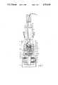
- FIG. 1shows a vibration damper, in cross section
- FIG. 2shows another embodiment of a vibration damper, in cross section
- FIG. 3shows a variant of the spring-loaded valve, also in cross section
- FIG. 4shows a two-tube shock absorber strut, in cross section
- FIG. 5shows a shock absorber strut cartridge for use in a shock absorber strut, in a plan view
- FIG. 6shows a one-tube gas pressure damper, in cross section
- FIG. 7shows a one-tube damper with an external gas reservoir for use in a level regulating installation, in cross section
- FIG. 8shows an embodiment of the invention wherein a biased spring valve consists of a helical spring and a washer.
- the vibration damper illustrated in FIG. 1consists essentially of a piston rod 1 and a damping piston 2, which divides a work cylinder 3 into an upper chamber half 4 and a lower chamber half 5.
- the damping piston 2is equipped with valves 23 and 24, for the production of a damping force.
- the upper chamber half 4is also connected via a bypass connection with the lower chamber half 5.
- This bypass connectioncomprises a transverse boring 6 and a longitudinal boring 7.
- a passage 11is pressurized by a valve body 12, whereby the valve body 12 is a component of an electromagnet comprising a coil 8 and an armature 9.
- the valve body 12is thereby configured directly as the armature 9 and housed in a cavity 16.
- a bypass valve 10behind the passage 11 in the bypass connection.
- the bypass valve 10is located in a cavity 17 and comprises throttle borings 14, which are controlled by valve spring washers 15, so that a spring-loaded valve 13 exercises full control of the bypass as a function of the pressure. For the low range of piston velocities, the spring-loaded valve 13 also exhibits a constant throttle opening 20.
- the coil 8 and the armature 9are located in the end region of the piston rod 1, whereby the bypass valve 10, together with a plate containing the passage 11, is a component of an intermediate sleeve 18, which is connected with the piston rod 1 by means of a threaded connection 25.
- the electrical feed 26runs through a hole in the piston rod 1.
- This embodimentmakes possible assembly by groups of components, whereby the bypass control and the bypass valve itself is a component of the piston rod 1, so that, where necessary for a mass-produced vibration damper, for a one-tube or two-tube damper and for a shock absorber strut cartridge, not only is installation easy, but so is any subsequent replacement which may be necessary.
- a helical spring 19is disposed between the valve body 12 and the base of the electromagnet keeps the passage 11 closed when no current is fed to the coil 8, so that, if the electromagnet should fail, the damper automatically assumes the tighter setting.
- FIG. 2illustrates an embodiment in which the bypass valve 10 is also designed as a spring-loaded valve, and throttle borings 14 are opened and closed by valve spring washers 15.
- This spring-loaded valve 10also exhibits a stop 21, which limits the axial travel of the valve spring washer 15.
- a defined opening cross-sectionis established above a specified pressure.
- the bypass valve 10has a second valve seat 22, with which the valve spring washers 15 come into contact above a specified pressure, so that the bypass is again closed above this pressure, so that when the passage 11 is opened by the valve body 12, the bypass connection is again closed. As soon as the pressure in the decompression phase drops, the bypass connection is re-established automatically.
- FIG. 4shows one application of the bypass valve in a twotube shock absorber strut, whereby an electrical feed 26 is the only element which has to be introduced externally.
- Embodiments of the inventioncan thereby be used in a shock absorber strut cartridge as a replacement for a shock absorber strut. Because of the components located inside it and the fact that there is only one element which has to be introduced from the outside, namely the electrical feed 26, the replacement of the entire cartridge is possible without any additional expense, as illustrated in FIG. 5.
- the systemcan be easily used in a one-tube gas pressure damper, as shown in FIG. 6, and also in the embodiment illustrated in FIG. 7, in which a gas pressure reservoir 27 is located outside the work cylinder.
- the electrical feed 26is the only external component.
Landscapes
- Engineering & Computer Science (AREA)
- Mechanical Engineering (AREA)
- General Engineering & Computer Science (AREA)
- Fluid-Damping Devices (AREA)
Abstract
Description
1. Field of the Invention
The present invention relates to vibration dampers and, more particularly, to adjustable hydraulic vibration dampers.
The hydraulic adjustable vibration dampers have a damping piston fastened to a piston rod, which divides the work cylinder into two chamber halves filled with damping fluid. A bypass, formed by a transverse boring located above the damping piston and a longitudinal boring at least in the termal region of the piston rod, connects the upper half of the chamber with the lower half of the chamber. There is an axially-movable adjustment apparatus to adjust the damping force connected with an electromagnet, consisting of a coil and armature, to control the bypass.
2. Description of the Prior Art
Federal Republic of Germany Laid Open Patent Application No. DE-OS No. 33 03 293 describes damping force regulation devices for telescoping shock absorbers on which there is an additional double-acting damping valve, which is incorporated into the damping piston itself. These damping valves are connected in series and can be separated from one another by means of a rotary disc valve. In a first valve position, only the valve of the damping piston is carrying a flow, so that a mild damping action can be achieved. In a second valve position, the valve in the damping piston and the additional valve both carry flows, so that a correspondingly hard damping characteristic can be achieved.
A disadvantage with such an embodiment is that the rotary disc valve must be pressurized by appropriate adjustment forces, which can only be applied by slow-acting drives, such as pneumatically or hydraulically driven positioning mechanisms, or an electrically-driven positioning motor.
In Federal Republic of Germany Patent No. DE-PS 29 11 768, there are described adjustable shock absorbers in which there is a coil in the upper part of the piston rod and in which an armature can move axially. As a function of the current fed to the coil, a specified bypass opening can be created between the upper and lower work chamber. A disadvantage with this arrangement is that, by controlling a change in the cross section, it is not possible to achieve an optimal damping force characteristic. The cross section modification which can be achieved corresponds to the regularities of a simple throttle hole, whereby with increasing piston velocities, an undesirable progressive damping characteristic always takes over. Both of the above-mentioned Federal Republic of Germany Patent Publications are incorporated herein by reference as if they were set forth herein in their entirety.
An object of the invention is to create, inside the piston rod of a vibration damper, an apparatus for the variable adjustment of the damping, in which, by means of a variably controllable damping valve, any desired degree of damping in the decompression and compression phases can be attained.
A further object of the invention is to use as many standard parts as possible.
A yet further object of the invention is to incorporate the invention in a replaceable strut cartridge.
These objectives are achieved by the invention in that the bypass valve in the bypass consists of an axially-movable valve body which interacts with a passage and which can be controlled by the adjustment apparatus, and at least one pressure-dependent spring-loaded valve arranged in series with the valve body.
An advantage with this solution is that the bypass operates parallel to the conventional throttle valves in the damping piston. By means of the axially-moving controllable valve body, the bypass valve can be positioned with the valves of the damping piston, so that there is a larger overall passage, which causes a correspondingly reduced throttle action, that is, damping. In this manner, different damping characteristics with the required extensive variability can be produced.
One important feature of an embodiment of the invention is that the spring-loaded valve consists of throttle borings and the valve spring washers which close the throttle borings. One advantage is that there are separate throttle holes and valve spring washers for the decompression and compression phase.
In another embodiment of the invention, the bypass between the transverse boring and the longitudinal boring exhibits two cavities connected with one another via a passage, whereby the electromagnet and the adjustment apparatus controlling the passage are located in the first cavity, and the spring-loaded valve is located in the second cavity.
A simple and economical embodiment is achieved by making the first cavity a component of the piston rod and the second cavity a component of an intermediate sleeve connected with the piston rod and holding the damping piston.
An additional variability of the damping force characteristic is achieved if, as in one embodiment of the invention, the passage and the valve body exhibit a cross section corresponding to a throttle.
To make certain that, in case of failure of the bypass valve control, the tighter and thus safer damping characteristic is assured, another characteristic of the invention provides that the valve body be pressurized by a spring so that it closes the passage when no current is fed to the coil. Thus, the bypass valve, which makes the ride more comfortable but which cannot be operated for long periods of time in extreme cases, is mechanically excluded from the circuit.
A preferred embodiment of the invention provides that the spring-loaded valve is designed as a spring washer valve, or comprises at least one spring washer and at least one helical spring. In addition, the spring-loaded valve can also comprise a plate and at least one helical spring.
In one embodiment of the invention, the spring-loaded valve can exhibit a continuously-open, constant throttle cross section, which acts on the damping force in the lower piston velocity range.
In another advantageous embodiment of the invention, the spring-loaded valve exhibits at least one stop which limits the movement of the valve spring washers, or the spring-loaded valve exhibits at least one other valve seat which limits the movement of the valve spring washer, whereby the valve spring washer closes the flow connection after a defined excursion of the valve spring washer.
To achieve a soft damping action, another important variant has the spring-loaded valve located in the bypass connected hydraulically in parallel to the valves located in the damping piston. By switching the bypass valve, a parallel flow connection is thereby created.
The above, as well as other features and advantages of the present invention, can be more readily appreciated through consideration of the detailed description of preferred embodiments in conjunction with the drawings, in which:
FIG. 1 shows a vibration damper, in cross section;
FIG. 2 shows another embodiment of a vibration damper, in cross section;
FIG. 3 shows a variant of the spring-loaded valve, also in cross section;
FIG. 4 shows a two-tube shock absorber strut, in cross section;
FIG. 5 shows a shock absorber strut cartridge for use in a shock absorber strut, in a plan view;
FIG. 6 shows a one-tube gas pressure damper, in cross section;
FIG. 7 shows a one-tube damper with an external gas reservoir for use in a level regulating installation, in cross section; and
FIG. 8 shows an embodiment of the invention wherein a biased spring valve consists of a helical spring and a washer.
The vibration damper illustrated in FIG. 1 consists essentially of a piston rod 1 and adamping piston 2, which divides awork cylinder 3 into anupper chamber half 4 and alower chamber half 5. Thedamping piston 2 is equipped withvalves
Theupper chamber half 4 is also connected via a bypass connection with thelower chamber half 5. This bypass connection comprises atransverse boring 6 and alongitudinal boring 7. Inside this bypass connection, apassage 11 is pressurized by avalve body 12, whereby thevalve body 12 is a component of an electromagnet comprising acoil 8 and an armature 9. Thevalve body 12 is thereby configured directly as the armature 9 and housed in acavity 16. Moreover, there is abypass valve 10 behind thepassage 11 in the bypass connection. Thebypass valve 10 is located in acavity 17 and comprisesthrottle borings 14, which are controlled byvalve spring washers 15, so that a spring-loaded valve 13 exercises full control of the bypass as a function of the pressure. For the low range of piston velocities, the spring-loaded valve 13 also exhibits aconstant throttle opening 20.
To simplify fabrication and installation, thecoil 8 and the armature 9 are located in the end region of the piston rod 1, whereby thebypass valve 10, together with a plate containing thepassage 11, is a component of anintermediate sleeve 18, which is connected with the piston rod 1 by means of a threadedconnection 25. Theelectrical feed 26 runs through a hole in the piston rod 1.
This embodiment makes possible assembly by groups of components, whereby the bypass control and the bypass valve itself is a component of the piston rod 1, so that, where necessary for a mass-produced vibration damper, for a one-tube or two-tube damper and for a shock absorber strut cartridge, not only is installation easy, but so is any subsequent replacement which may be necessary.
Ahelical spring 19 is disposed between thevalve body 12 and the base of the electromagnet keeps thepassage 11 closed when no current is fed to thecoil 8, so that, if the electromagnet should fail, the damper automatically assumes the tighter setting.
FIG. 2 illustrates an embodiment in which thebypass valve 10 is also designed as a spring-loaded valve, and throttle borings 14 are opened and closed byvalve spring washers 15. This spring-loadedvalve 10 also exhibits astop 21, which limits the axial travel of thevalve spring washer 15. In the decompression phase, in this embodiment, a defined opening cross-section is established above a specified pressure.
In FIG. 3, thebypass valve 10 has a second valve seat 22, with which thevalve spring washers 15 come into contact above a specified pressure, so that the bypass is again closed above this pressure, so that when thepassage 11 is opened by thevalve body 12, the bypass connection is again closed. As soon as the pressure in the decompression phase drops, the bypass connection is re-established automatically.
FIG. 4 shows one application of the bypass valve in a twotube shock absorber strut, whereby anelectrical feed 26 is the only element which has to be introduced externally. Embodiments of the invention can thereby be used in a shock absorber strut cartridge as a replacement for a shock absorber strut. Because of the components located inside it and the fact that there is only one element which has to be introduced from the outside, namely theelectrical feed 26, the replacement of the entire cartridge is possible without any additional expense, as illustrated in FIG. 5.
The system can be easily used in a one-tube gas pressure damper, as shown in FIG. 6, and also in the embodiment illustrated in FIG. 7, in which agas pressure reservoir 27 is located outside the work cylinder. In each case, theelectrical feed 26 is the only external component.
The invention as described hereinabove in the context of preferred embodiments is not to be taken as limited to all of the provided details thereof, since modifications and variations thereof may be made without departing from the spirit and scope of the invention.
Claims (14)
1. A hydraulic vibration damper with adjustable damping with a hydraulic cylinder filled with damping fluid, said vibration damper having piston means comprising a piston fastened to a piston rod, said piston means being disposed in said hydraulic cylinder, said piston dividing said cylinder into two chambers, said piston rod having a longitudinal axis;
bypass means disposed to bypass damping fluid through said piston means;
said bypass means having disposed, hydraulically in series, therein pressure dependent, biased valve means and electromagnetically-controlled valve means;
said electromagnetically-controlled valve means comprising an orifice and a movable body, said body being disposed for opening and closing said orifice during an adjusting operation of said vibration damper, said electromagnetically-controlled valve means providing the sole fluid communication between said two chambers for fluid flowing through said pressure dependent, biased valve means; and
means for electrically connecting said electromagnetically-controlled valve means to an external power source, whereby a damping force of said vibration damper is externally adjustable by energization of said electromagnetically-controlled valve means;
said pressure-dependent, biased valve means comprising spring-loaded valve means, said spring-loaded valve means having at least one throttle opening and at least one valve spring washer being biased and disposed such that said at least one throttle opening is normally in a first, closed seated position at no pressure difference thereacross;
said spring-loaded valve means comprises at least one other valve seat for limiting opening movement of said valve spring washer and for closing said valve spring washer thereagainst for stopping flow through said bypass means after said valve spring washer has made a predetermined excursion under pressure, said valve spring washer being bendable from said first seated position to a second seated position against said at least one other valve seat on over pressure.
2. The vibration damper according to claim 1, wherein said at least one throttle opening and said at least one valve spring washer are disposed to open at given pressures during decompression and compression of said vibration damper.
3. The vibration damper according to claim 2, wherein said bypass means further comprises, in series with said pressure-dependent, biased valve means and said electromagnetically-controlled valve means, at least one first opening having a longitudinal axis disposed transversely to said piston rod longitudinal axis and a second opening having a longitudinal axis aligned with said piston rod longitudinal axis, and further comprising two cavities for being hydraulically connected to one another by said orifice, and wherein said body has a longitudinal axis which is aligned with said piston rod longitudinal axis and disposed to move back and forth as said electromagnetically-controlled valve means is energized and de-energized.
4. The vibration damper according to claim 1, wherein said bypass means further comprises, in series with said pressure-dependent, biased valve means and said electromagnetically-controlled valve means, at least one first opening having a longitudinal axis disposed transversely to said piston rod longitudinal axis and a second opening having a longitudinal axis substantially aligned with said piston rod longitudinal axis, and further comprising two cavities for being hydraulically connected to one another by said orifice, and wherein said body has a longitudinal axis which is substantially aligned with said piston rod longitudinal axis and disposed to move back and forth as said electromagnetically-controlled valve means is energized and de-energized.
5. The vibration damper according to claim 4, wherein said electromagnetically-controlled valve means is disposed in a first of said two cavities and said spring-loaded valve is disposed in a second of said two cavities.
6. The vibration damper according to claim 5, wherein said first cavity is disposed in a first portion of said piston rod and said second cavity is disposed in a second portion of said piston rod, said second portion of said piston rod comprising an intermediate sleeve for holding and connecting said piston rod with said piston.
7. The vibration damper according to claim 6, including at least one bypass valve disposed in said piston for hydraulically bypassing damping fluid between said two chambers in addition to fluid bypassed by said bypass means.
8. The vibration damper according to claim 1, wherein said bypass means further comprises, in series with said pressure-dependent, biased valve means and said electromagnetically-controlled valve means, at least one first opening having a longitudinal axis disposed transversely to said piston rod longitudinal axis and a second opening having a longitudinal axis aligned with said piston rod longitudinal axis, and further comprising two cavities for being hydraulically connected to one another by said orifice, and wherein said body has a longitudinal axis which is aligned with said piston rod longitudinal axis and disposed to move back and forth as said electromagnetically-controlled valve means is energized and de-energized.
9. The vibration damper according to claim 1, wherein said body is disposed, in operation, such as to permit flow through said orifice when said electromagnetically-controlled valve means is energized.
10. The vibration damper according to claim 1, including a spring or biasing said body in a closed position against said orifice when said electromagnetically-controlled valve means is de-energized, whereby damping of said vibration damper is maximized when said electromagnetically-controlled valve means is de-energized.
11. The vibration damper according to claim 1, wherein said biased valve means comprises spring-loaded valve means, and wherein said spring-loaded valve means comprises at least one spring washer and at least one helical spring.
12. The vibration damper according to claim 1, wherein said biased valve means comprises spring-loaded valve means, and wherein said spring-loaded valve means comprises a washer and at least one helical spring.
13. The vibration damper according to claim 1, wherein said biased valve means includes at least one continuously open constant throttle cross-section means.
14. The vibration damper according to claim 1, including at least one bypass valve disposed in said piston for hydraulically bypassing damping fluid between said two chambers in addition to fluid bypassed by said bypass means.
Applications Claiming Priority (2)
| Application Number | Priority Date | Filing Date | Title |
|---|---|---|---|
| DE3518327 | 1985-05-22 | ||
| DE19853518327DE3518327A1 (en) | 1985-05-22 | 1985-05-22 | HYDRAULIC, ADJUSTABLE VIBRATION DAMPER |
Publications (1)
| Publication Number | Publication Date |
|---|---|
| US4723640Atrue US4723640A (en) | 1988-02-09 |
Family
ID=6271307
Family Applications (1)
| Application Number | Title | Priority Date | Filing Date |
|---|---|---|---|
| US06/864,451Expired - LifetimeUS4723640A (en) | 1985-05-22 | 1986-05-16 | Adjustable hydraulic vibration damper |
Country Status (4)
| Country | Link |
|---|---|
| US (1) | US4723640A (en) |
| BR (1) | BR8602195A (en) |
| DE (1) | DE3518327A1 (en) |
| IT (1) | IT1204771B (en) |
Cited By (62)
| Publication number | Priority date | Publication date | Assignee | Title |
|---|---|---|---|---|
| US4846317A (en)* | 1987-08-25 | 1989-07-11 | Trw Inc. | Strut with controlled variable damping rate |
| US4872702A (en)* | 1988-08-23 | 1989-10-10 | Kress Corporation | Suspension system for vehicles |
| US4893699A (en)* | 1987-04-01 | 1990-01-16 | Robert Bosch Gmbh | Shock absorber |
| GB2220726A (en)* | 1988-06-07 | 1990-01-17 | Tokico Ltd | A hydraulic damper of adjustable damping force type |
| US4905798A (en)* | 1987-04-01 | 1990-03-06 | Robert Bosch Gmbh | Shock absorber |
| GB2223822A (en)* | 1988-09-07 | 1990-04-18 | Fichtel & Sachs Ag | Hydraulic vibration damper with variable damping force |
| US4923038A (en)* | 1986-06-05 | 1990-05-08 | Lizell Magnus B | Method and apparatus for absorbing mechanical shock |
| US4943083A (en)* | 1989-03-13 | 1990-07-24 | Monroe Auto Equipment Company | Signal conditioning circuit assembly |
| US4986393A (en)* | 1988-02-09 | 1991-01-22 | Boge Ag | Adjustable vibration dampers for motor vehicles |
| US4993693A (en)* | 1988-05-11 | 1991-02-19 | Boge Ag | Self-pumping hydropneumatic shock absorbing leg with internal level regulation |
| US5020825A (en)* | 1987-03-18 | 1991-06-04 | Monroe Auto Equipment Company | Method and apparatus for absorbing mechanical shock |
| US5035306A (en)* | 1988-12-14 | 1991-07-30 | Tokico Ltd. | Adjustable damping force hydraulic shock absorber |
| US5062616A (en)* | 1989-04-29 | 1991-11-05 | Boge Ag | Self-pumping hydropneumatic shock absorbing strut |
| US5078240A (en)* | 1989-07-21 | 1992-01-07 | Boge Ag | Adjustable vibration damper with valve body in piston having directional flow control |
| US5078239A (en)* | 1988-07-08 | 1992-01-07 | Nippondenso Co., Ltd. | Shock absorber with adjustable damping force |
| US5085299A (en)* | 1989-05-26 | 1992-02-04 | Robert Bosch Gmbh | Shock absorber with two seat valve |
| GB2247303A (en)* | 1990-07-11 | 1992-02-26 | Fichtel & Sachs Ag | Magnetically operated valve device. |
| US5092626A (en)* | 1989-03-13 | 1992-03-03 | Monroe Auto Equipment Company | Apparatus for controlling the damping of a shock absorber |
| US5123671A (en)* | 1989-03-13 | 1992-06-23 | Monroe Auto Equipment Company | Method and apparatus for controlling shock absorbers |
| US5152379A (en)* | 1990-04-16 | 1992-10-06 | Monroe Auto Equipment Company | Adjustable shock absorber assembly |
| US5205385A (en)* | 1990-07-20 | 1993-04-27 | Tokico, Ltd. | Adjustable damping force hydraulic shock absorber |
| US5207300A (en)* | 1990-06-29 | 1993-05-04 | Boge Aktiengesellschaft | Hydraulic, adjustable vibration damper for motor vehicles |
| US5217095A (en)* | 1986-06-05 | 1993-06-08 | Monroe Auto Equipment Company | Method and apparatus for absorbing mechanical shock |
| US5251728A (en)* | 1989-07-05 | 1993-10-12 | Boge Ag | Hydraulic vibration damper or shock absorber with electrical control connections and connector therefor |
| US5303803A (en)* | 1990-04-07 | 1994-04-19 | August Bilstein Gmbh & Co. Kg | Variable dashpot for motor vehicles |
| US5423347A (en)* | 1990-11-30 | 1995-06-13 | Weber; Guenter | Threaded insertion valve |
| US5551540A (en)* | 1994-01-15 | 1996-09-03 | Fichtel & Sachs Ag | Vibration damper and a vibration damper with a valve actuation device |
| US5950775A (en)* | 1997-08-12 | 1999-09-14 | Achmad; Muchlis | In-tube shock absorber mounted electromagnetically operated damper valve and shock absorber including adapter |
| WO2000009912A1 (en)* | 1998-08-11 | 2000-02-24 | Krupp Bilstein Gmbh | Hydraulic vibration damper for motor vehicles |
| US6053510A (en)* | 1998-02-03 | 2000-04-25 | Ford Motor Company | Vehicle active tilt control system with improved actuators |
| US6273224B1 (en)* | 1997-08-12 | 2001-08-14 | Hr Textron, Inc. | Shock absorber mounted electromagnetically operated damper valve |
| US6343676B1 (en) | 2000-01-24 | 2002-02-05 | Hr Textron, Inc. | Shock absorber mounted real time damper valve |
| US6561326B2 (en)* | 2000-05-04 | 2003-05-13 | Krupp Bilstein Gmbh | Amplitude-attenuating dashpot |
| US20030150679A1 (en)* | 2002-02-13 | 2003-08-14 | Dirk Feist | Shock-absorbing piston for hydraulic fixtures |
| EP1326030A3 (en)* | 2002-01-08 | 2003-12-17 | Delphi Technologies, Inc. | Active hydraulic fluid vehicular suspension damper |
| US20040173423A1 (en)* | 2003-03-06 | 2004-09-09 | Jurgen Adamek | Hydraulic dashpot for motor vehicles |
| US20040200946A1 (en)* | 2003-04-12 | 2004-10-14 | Zf Sachs Ag | Vibration damper with amplitude-selective damping force |
| US6860369B2 (en)* | 1998-10-26 | 2005-03-01 | Mannesmann Sachs Ag | Vibration damper with variable damping force |
| US20050045440A1 (en)* | 2001-11-06 | 2005-03-03 | Kock Paul De | Shock absorber with frequency-dependent damping |
| EP1544498A1 (en)* | 2003-12-20 | 2005-06-22 | DaimlerChrysler AG | Damping device for a vehicle |
| EP1006292B1 (en)* | 1998-12-02 | 2006-04-05 | Öhlins Racing Ab | Shock absorber |
| US20070170026A1 (en)* | 2003-07-08 | 2007-07-26 | Thyssenkrupp Bilstein Suspension Gmbh | Dashpot with amplitude-dependent shock absorption |
| US20080078634A1 (en)* | 2006-09-30 | 2008-04-03 | Zf Friedrichshafen Ag | Adjustable damping valve with a fail-safe damping force characteristic |
| CN102472352A (en)* | 2009-08-25 | 2012-05-23 | 蒂森克虏伯比尔斯坦悬架有限公司 | Motor vehicle shock absorber |
| US20130126282A1 (en)* | 2010-08-04 | 2013-05-23 | Sistemi Sospensioni S.P.A. | Piston for a damping-adjustable shock-absorber, particularly for a vehicle suspension, provided with four passive flow-control valves and with a flow-dividing solenoid valve |
| US9441700B2 (en)* | 2014-08-14 | 2016-09-13 | Tenneco Automotive Operating Company Inc. | Shock absorber with frequency dependent passive valve |
| US9695900B2 (en) | 2009-10-06 | 2017-07-04 | Tenneco Automotive Operating Company Inc. | Damper with digital valve |
| JP2017524112A (en)* | 2014-08-14 | 2017-08-24 | テネコ オートモティブ オペレーティング カンパニー インコーポレイテッドTenneco Automotive Operating Company Inc. | Shock absorber with frequency-dependent passive valve |
| US9802456B2 (en) | 2013-02-28 | 2017-10-31 | Tenneco Automotive Operating Company Inc. | Damper with integrated electronics |
| US9879748B2 (en) | 2013-03-15 | 2018-01-30 | Tenneco Automotive Operating Company Inc. | Two position valve with face seal and pressure relief port |
| US9879746B2 (en) | 2013-03-15 | 2018-01-30 | Tenneco Automotive Operating Company Inc. | Rod guide system and method with multiple solenoid valve cartridges and multiple pressure regulated valve assemblies |
| US9884533B2 (en) | 2013-02-28 | 2018-02-06 | Tenneco Automotive Operating Company Inc. | Autonomous control damper |
| US9925842B2 (en) | 2013-02-28 | 2018-03-27 | Tenneco Automotive Operating Company Inc. | Valve switching controls for adjustable damper |
| CN107975560A (en)* | 2016-10-21 | 2018-05-01 | 大众汽车有限公司 | Valve-piston structure for damper |
| US10393210B2 (en)* | 2016-11-18 | 2019-08-27 | Beijingwest Industries Co., Ltd. | Dual mode hydraulic damper |
| US10479160B2 (en) | 2017-06-06 | 2019-11-19 | Tenneco Automotive Operating Company Inc. | Damper with printed circuit board carrier |
| US10588233B2 (en) | 2017-06-06 | 2020-03-10 | Tenneco Automotive Operating Company Inc. | Damper with printed circuit board carrier |
| US10746247B2 (en)* | 2018-03-05 | 2020-08-18 | Beijingwest Industries Co., Ltd. | Dual ride damper assembly |
| US11204074B2 (en)* | 2017-09-05 | 2021-12-21 | Hitachi Astemo, Ltd. | Shock absorber |
| US20220018417A1 (en)* | 2019-03-26 | 2022-01-20 | Hitachi Astemo, Ltd. | Damping force adjustable shock absorber |
| US11242906B2 (en)* | 2019-03-26 | 2022-02-08 | Mando Corporation | Variable damping force shock absorber |
| US12214641B2 (en) | 2021-10-20 | 2025-02-04 | Beijingwest Industries Co., Ltd. | Variable stiffness hydraulic damper |
Families Citing this family (33)
| Publication number | Priority date | Publication date | Assignee | Title |
|---|---|---|---|---|
| DE3518327A1 (en) | 1985-05-22 | 1986-11-27 | Boge Gmbh, 5208 Eitorf | HYDRAULIC, ADJUSTABLE VIBRATION DAMPER |
| DE3532293C2 (en)* | 1985-09-11 | 1994-09-22 | Fichtel & Sachs Ag | Vibration damper with adjustable damping force |
| DE3534298A1 (en)* | 1985-09-26 | 1987-04-02 | Fichtel & Sachs Ag | Hydraulically acting vibration damper with adjustable damping force |
| EP0241677B1 (en)* | 1986-04-12 | 1990-05-02 | Körber Ag | Damper with adjustable damping characteristics |
| US4785920A (en)* | 1986-04-16 | 1988-11-22 | Boge Ag | Hydraulic adjustable shock absorber |
| DE3709447A1 (en)* | 1987-03-23 | 1988-10-13 | Bilstein August Gmbh Co Kg | ADJUSTABLE SHOCK ABSORBER, ESPECIALLY FOR MOTOR VEHICLES |
| JPS63259236A (en)* | 1987-04-13 | 1988-10-26 | ボーゲ・アクチェンゲゼルシャフト | Adjustable hydraulic type shock absorber |
| DE3724361A1 (en)* | 1987-07-23 | 1989-02-02 | Bilstein August Gmbh Co Kg | SHOCK ABSORBER, ESPECIALLY FOR MOTOR VEHICLES |
| US4836342A (en)* | 1987-08-07 | 1989-06-06 | Lord Corporation | Controllable fluid damper assembly |
| DE3729187C2 (en)* | 1987-09-01 | 1995-01-26 | Rexroth Mannesmann Gmbh | Adjustable cushioning |
| US4854429A (en)* | 1987-12-18 | 1989-08-08 | Casey Gary L | Variable rate shock absorber and system therefor |
| DE3814480A1 (en)* | 1988-04-29 | 1989-11-09 | Bosch Gmbh Robert | Device for damping movement sequences |
| DE3823430C3 (en)* | 1988-07-11 | 1997-04-17 | Daimler Benz Ag | Hydraulic telescopic shock absorber |
| JP2639396B2 (en)* | 1988-07-11 | 1997-08-13 | ダイムラー―ベンツ・アクチエンゲゼルシヤフト | Hydraulic telescopic shock absorber |
| DE3824611A1 (en)* | 1988-07-20 | 1990-01-25 | Bayerische Motoren Werke Ag | SPRING-DAMPER SYSTEM FOR VEHICLES |
| DE3841166A1 (en)* | 1988-12-07 | 1989-11-09 | Daimler Benz Ag | Hydraulic oscillation damper |
| DE3911819A1 (en)* | 1989-04-11 | 1990-10-18 | Hauni Werke Koerber & Co Kg | SHOCK ABSORBER WITH CHANGEABLE DAMPING CHARACTERISTICS |
| JP2964148B2 (en)* | 1989-04-20 | 1999-10-18 | トキコ株式会社 | Damping force adjustable hydraulic shock absorber |
| DE3927150A1 (en)* | 1989-08-17 | 1991-02-21 | Fichtel & Sachs Ag | Magnetic valve with short stroke armature - pole cure and magnetic armature cooperating via protrusion and corresp. recess |
| DE4039236C1 (en)* | 1990-02-01 | 1992-05-27 | August Bilstein Gmbh & Co. Kg, 5828 Ennepetal, De | Control valve for hydraulic shock absorber of motor vehicle - uses electromagnet to increase force of permanent magnet and open by=pass against mechanical spring force closing by=pass |
| DE4002883A1 (en)* | 1990-02-01 | 1991-08-08 | Bilstein August Gmbh Co Kg | By=pass valve for vehicle hydraulic damper - has two stable positions with solenoid switching action |
| DE4120122A1 (en)* | 1990-06-29 | 1992-01-09 | Boge Ag | Hydraulic adjustable damper for vehicle - incorporates by=pass arrangement to vary damping properties |
| DE4025880A1 (en)* | 1990-08-16 | 1992-02-20 | Bilstein August Gmbh Co Kg | Controllable hydraulic vibration damper for vehicle bodywork - has damping piston at piston rod in cylinder which has valve discs for variable passage openings and by=pass controlled by electromagnet |
| DE4129230A1 (en)* | 1990-09-14 | 1992-03-19 | Boge Ag | Adjustable shock absorber for vehicle - makes use of control surfaces subject to hydraulic and/or mechanical forces |
| DE4041930A1 (en)* | 1990-12-27 | 1992-07-02 | Bilstein August Gmbh Co Kg | ADJUSTABLE VIBRATION DAMPER FOR MOTOR VEHICLES WITH AN ADJUSTABLE BYPASS VALVE |
| DE4105771A1 (en)* | 1991-02-23 | 1992-08-27 | Boge Ag | Hydraulic adjustable vibration damper for vehicle - involves controlling pressure forces in damping valve |
| RU2127675C1 (en)* | 1998-07-27 | 1999-03-20 | Стравинский Игорь Александрович | Method of and device to control resistance force of hydraulic damper (design versions) |
| FR2800141B1 (en) | 1999-10-26 | 2002-04-12 | Mannesmann Sachs Ag | OSCILLATION SHOCK ABSORBER WITH VARIABLE DAMPING FORCE |
| US6460664B1 (en)† | 2000-05-22 | 2002-10-08 | Tenneco Automotive Inc. | Independently tunable variable bleed orifice |
| DE10123827C1 (en)* | 2001-05-16 | 2003-01-16 | Zf Sachs Ag | Automobile wheel suspension has adjustable shock absorber coupled to mounting spring via linkage |
| DE102007009012B3 (en)* | 2007-02-23 | 2008-06-19 | Zf Friedrichshafen Ag | Piston/cylinder aggregate unit with dampening unit for hydraulic system |
| DE102012016711A1 (en)* | 2012-08-22 | 2014-02-27 | Volkswagen Aktiengesellschaft | Piston valve assembly for switching-type vibration damper for motor vehicle, has piston which is formed as pre-assembly with switching valve and valve elements accommodated in and outside the housing |
| DE102014214654B4 (en)* | 2014-07-25 | 2023-07-20 | Volkswagen Aktiengesellschaft | Valve-piston arrangement for a vibration damper |
Citations (13)
| Publication number | Priority date | Publication date | Assignee | Title |
|---|---|---|---|---|
| US2264111A (en)* | 1937-07-02 | 1941-11-25 | L A Simon | Stabilizer |
| US2934175A (en)* | 1956-05-15 | 1960-04-26 | Schnitzer Emanuel | Band pass shock strut |
| DE2413833A1 (en)* | 1974-03-22 | 1975-09-25 | Volkswagenwerk Ag | Vehicle suspension telescopic damper - has second non-return valve in flow passage through piston in one direction |
| US3991659A (en)* | 1973-12-06 | 1976-11-16 | Robinson Morris D | Fail safe apparatus for load lifts |
| DE2911768A1 (en)* | 1979-03-26 | 1980-10-02 | F & O Electronic Systems | Vehicle hydraulic shock absorber cylinder - is adjustable by means of internal solenoid valve |
| US4313529A (en)* | 1978-11-10 | 1982-02-02 | Tokico Ltd. | Hydraulic damper |
| US4352417A (en)* | 1980-10-03 | 1982-10-05 | Ford Motor Company | Control valve for shock absorber pistons and the like |
| DE3303293A1 (en)* | 1982-02-01 | 1984-01-05 | Kayaba Kogyo K.K., Tokyo | DAMPING FORCE CONTROL DEVICE UER TELESCOPIC SHOCK ABSORBER |
| JPS59197638A (en)* | 1983-04-25 | 1984-11-09 | Atsugi Motor Parts Co Ltd | hydraulic shock absorber |
| GB2143390A (en)* | 1983-05-20 | 1985-02-06 | Tokico Ltd | Hydraulic shock absorber |
| US4535877A (en)* | 1982-07-14 | 1985-08-20 | Tokico Ltd. | Hydraulic damper of adjustable damping force type |
| US4600215A (en)* | 1984-02-29 | 1986-07-15 | Nissan Motor Company, Limited | Vehicular suspension control system with variable damping characteristics depending upon road condition and vehicle speed |
| US4615420A (en)* | 1984-01-23 | 1986-10-07 | Ford Motor Company | Piston assembly for shock absorber |
Family Cites Families (19)
| Publication number | Priority date | Publication date | Assignee | Title |
|---|---|---|---|---|
| DE894965C (en)* | 1943-10-21 | 1953-10-29 | Hemscheidt Maschf Hermann | Vibration dampers, stabilizers or similar hydraulic devices connected between a sprung and an unsprung mass, especially for vehicles |
| GB835234A (en)* | 1955-09-27 | 1960-05-18 | Armstrong Patents Co Ltd | Improvements in or relating to hydraulic shock absorbers for vehicle suspension |
| DE1405781B1 (en)* | 1960-12-01 | 1970-06-18 | Armstrong Patents Co Ltd | Electrically remote controllable hydraulic shock absorbers, especially for land vehicles |
| GB1021877A (en)* | 1963-12-18 | 1966-03-09 | Armstrong Patents Co Ltd | Improvements in or relating to adjustable hydraulic shock absorbers |
| FR2088803A5 (en)* | 1970-04-24 | 1972-01-07 | Citroen Sa | |
| GB1522795A (en)* | 1974-08-15 | 1978-08-31 | Lucas Industries Ltd | Damping device for a vehicle suspension |
| DE2721933C3 (en) | 1977-05-14 | 1981-06-11 | Boge Gmbh, 5208 Eitorf | Speed-dependent blocking valve device, in particular for hydraulic telescopic vibration dampers in motor vehicles |
| GB2111168B (en)* | 1981-11-06 | 1986-07-16 | Tokico Ltd | Hydraulic damper with bypass |
| US4620619A (en)* | 1982-05-20 | 1986-11-04 | Atsugi Motor Parts Co., Ltd. | Variable-damping-force shock absorber |
| FR2528140B1 (en)* | 1982-06-03 | 1985-10-11 | Messier Hispano Sa | FLUIDIC TYPE SHOCK ABSORBER |
| GB2123922A (en)* | 1982-06-15 | 1984-02-08 | Tokico Ltd | Hydraulic damper with adjustable flow path |
| DE3312899C2 (en)* | 1983-04-11 | 1985-06-13 | F & O Electronic Systems GmbH & Co, 6901 Neckarsteinach | Adjustable valve for the piston rod of a vibration damper |
| DE3346352C1 (en) | 1983-12-22 | 1985-01-24 | F & O Electronic Systems GmbH & Co, 6901 Neckarsteinach | Controllable valve for the piston rod of a vibration damper |
| JPS6052439U (en)* | 1983-09-20 | 1985-04-12 | トキコ株式会社 | Damping force adjustable hydraulic shock absorber |
| JPS6069711U (en)* | 1983-10-20 | 1985-05-17 | トキコ株式会社 | Damping force adjustable hydraulic shock absorber |
| SE443622B (en)* | 1984-04-04 | 1986-03-03 | Rolf Blixt | FOR SHOCK MUSHERS DESIGNED TO POSSIBLE VARIATION VARIATION VARIATION |
| DE3425988A1 (en)* | 1984-07-14 | 1986-01-23 | Boge Gmbh, 5208 Eitorf | Adjustable hydraulic shock absorber |
| DE3434877A1 (en)* | 1984-09-22 | 1986-04-17 | Boge Gmbh, 5208 Eitorf | HYDRAULIC, ADJUSTABLE SHOCK ABSORBER |
| DE3518327A1 (en) | 1985-05-22 | 1986-11-27 | Boge Gmbh, 5208 Eitorf | HYDRAULIC, ADJUSTABLE VIBRATION DAMPER |
- 1985
- 1985-05-22DEDE19853518327patent/DE3518327A1/enactiveGranted
- 1986
- 1986-01-22ITIT19148/86Apatent/IT1204771B/enactive
- 1986-05-15BRBR8602195Apatent/BR8602195A/ennot_activeIP Right Cessation
- 1986-05-16USUS06/864,451patent/US4723640A/ennot_activeExpired - Lifetime
Patent Citations (13)
| Publication number | Priority date | Publication date | Assignee | Title |
|---|---|---|---|---|
| US2264111A (en)* | 1937-07-02 | 1941-11-25 | L A Simon | Stabilizer |
| US2934175A (en)* | 1956-05-15 | 1960-04-26 | Schnitzer Emanuel | Band pass shock strut |
| US3991659A (en)* | 1973-12-06 | 1976-11-16 | Robinson Morris D | Fail safe apparatus for load lifts |
| DE2413833A1 (en)* | 1974-03-22 | 1975-09-25 | Volkswagenwerk Ag | Vehicle suspension telescopic damper - has second non-return valve in flow passage through piston in one direction |
| US4313529A (en)* | 1978-11-10 | 1982-02-02 | Tokico Ltd. | Hydraulic damper |
| DE2911768A1 (en)* | 1979-03-26 | 1980-10-02 | F & O Electronic Systems | Vehicle hydraulic shock absorber cylinder - is adjustable by means of internal solenoid valve |
| US4352417A (en)* | 1980-10-03 | 1982-10-05 | Ford Motor Company | Control valve for shock absorber pistons and the like |
| DE3303293A1 (en)* | 1982-02-01 | 1984-01-05 | Kayaba Kogyo K.K., Tokyo | DAMPING FORCE CONTROL DEVICE UER TELESCOPIC SHOCK ABSORBER |
| US4535877A (en)* | 1982-07-14 | 1985-08-20 | Tokico Ltd. | Hydraulic damper of adjustable damping force type |
| JPS59197638A (en)* | 1983-04-25 | 1984-11-09 | Atsugi Motor Parts Co Ltd | hydraulic shock absorber |
| GB2143390A (en)* | 1983-05-20 | 1985-02-06 | Tokico Ltd | Hydraulic shock absorber |
| US4615420A (en)* | 1984-01-23 | 1986-10-07 | Ford Motor Company | Piston assembly for shock absorber |
| US4600215A (en)* | 1984-02-29 | 1986-07-15 | Nissan Motor Company, Limited | Vehicular suspension control system with variable damping characteristics depending upon road condition and vehicle speed |
Cited By (89)
| Publication number | Priority date | Publication date | Assignee | Title |
|---|---|---|---|---|
| US5025899A (en)* | 1986-06-05 | 1991-06-25 | Lizell Magnus B | Method and apparatus for absorbing mechanical shock |
| US5217095A (en)* | 1986-06-05 | 1993-06-08 | Monroe Auto Equipment Company | Method and apparatus for absorbing mechanical shock |
| US4923038A (en)* | 1986-06-05 | 1990-05-08 | Lizell Magnus B | Method and apparatus for absorbing mechanical shock |
| US5020825A (en)* | 1987-03-18 | 1991-06-04 | Monroe Auto Equipment Company | Method and apparatus for absorbing mechanical shock |
| US4893699A (en)* | 1987-04-01 | 1990-01-16 | Robert Bosch Gmbh | Shock absorber |
| US4905798A (en)* | 1987-04-01 | 1990-03-06 | Robert Bosch Gmbh | Shock absorber |
| US4846317A (en)* | 1987-08-25 | 1989-07-11 | Trw Inc. | Strut with controlled variable damping rate |
| US4986393A (en)* | 1988-02-09 | 1991-01-22 | Boge Ag | Adjustable vibration dampers for motor vehicles |
| US4993693A (en)* | 1988-05-11 | 1991-02-19 | Boge Ag | Self-pumping hydropneumatic shock absorbing leg with internal level regulation |
| US4997068A (en)* | 1988-06-07 | 1991-03-05 | Tokico Ltd. | Hydraulic damper of adjustable damping force type |
| GB2220726A (en)* | 1988-06-07 | 1990-01-17 | Tokico Ltd | A hydraulic damper of adjustable damping force type |
| GB2220726B (en)* | 1988-06-07 | 1992-07-08 | Tokico Ltd | A hydraulic damper of adjustable damping force type |
| US5078239A (en)* | 1988-07-08 | 1992-01-07 | Nippondenso Co., Ltd. | Shock absorber with adjustable damping force |
| US4872702A (en)* | 1988-08-23 | 1989-10-10 | Kress Corporation | Suspension system for vehicles |
| GB2223822A (en)* | 1988-09-07 | 1990-04-18 | Fichtel & Sachs Ag | Hydraulic vibration damper with variable damping force |
| GB2223822B (en)* | 1988-09-07 | 1993-03-03 | Fichtel & Sachs Ag | Hydraulic vibration damper with variable damping force |
| US5035306A (en)* | 1988-12-14 | 1991-07-30 | Tokico Ltd. | Adjustable damping force hydraulic shock absorber |
| US5092626A (en)* | 1989-03-13 | 1992-03-03 | Monroe Auto Equipment Company | Apparatus for controlling the damping of a shock absorber |
| US5123671A (en)* | 1989-03-13 | 1992-06-23 | Monroe Auto Equipment Company | Method and apparatus for controlling shock absorbers |
| US4943083A (en)* | 1989-03-13 | 1990-07-24 | Monroe Auto Equipment Company | Signal conditioning circuit assembly |
| US5062616A (en)* | 1989-04-29 | 1991-11-05 | Boge Ag | Self-pumping hydropneumatic shock absorbing strut |
| US5085299A (en)* | 1989-05-26 | 1992-02-04 | Robert Bosch Gmbh | Shock absorber with two seat valve |
| US5251728A (en)* | 1989-07-05 | 1993-10-12 | Boge Ag | Hydraulic vibration damper or shock absorber with electrical control connections and connector therefor |
| US5078240A (en)* | 1989-07-21 | 1992-01-07 | Boge Ag | Adjustable vibration damper with valve body in piston having directional flow control |
| US5303803A (en)* | 1990-04-07 | 1994-04-19 | August Bilstein Gmbh & Co. Kg | Variable dashpot for motor vehicles |
| US5152379A (en)* | 1990-04-16 | 1992-10-06 | Monroe Auto Equipment Company | Adjustable shock absorber assembly |
| US5207300A (en)* | 1990-06-29 | 1993-05-04 | Boge Aktiengesellschaft | Hydraulic, adjustable vibration damper for motor vehicles |
| GB2247303A (en)* | 1990-07-11 | 1992-02-26 | Fichtel & Sachs Ag | Magnetically operated valve device. |
| GB2247303B (en)* | 1990-07-11 | 1995-01-11 | Fichtel & Sachs Ag | Oscillation damper for a motor vehicle |
| US5205385A (en)* | 1990-07-20 | 1993-04-27 | Tokico, Ltd. | Adjustable damping force hydraulic shock absorber |
| US5423347A (en)* | 1990-11-30 | 1995-06-13 | Weber; Guenter | Threaded insertion valve |
| US5551540A (en)* | 1994-01-15 | 1996-09-03 | Fichtel & Sachs Ag | Vibration damper and a vibration damper with a valve actuation device |
| ES2106667A1 (en)* | 1994-01-15 | 1997-11-01 | Fichtel & Sachs Ag | Vibration damper and a vibration damper with a valve actuation device |
| US5950775A (en)* | 1997-08-12 | 1999-09-14 | Achmad; Muchlis | In-tube shock absorber mounted electromagnetically operated damper valve and shock absorber including adapter |
| US6273224B1 (en)* | 1997-08-12 | 2001-08-14 | Hr Textron, Inc. | Shock absorber mounted electromagnetically operated damper valve |
| US6053510A (en)* | 1998-02-03 | 2000-04-25 | Ford Motor Company | Vehicle active tilt control system with improved actuators |
| WO2000009912A1 (en)* | 1998-08-11 | 2000-02-24 | Krupp Bilstein Gmbh | Hydraulic vibration damper for motor vehicles |
| US6460663B1 (en)* | 1998-08-11 | 2002-10-08 | Krupp Bilstein Gmbh | Hydraulic vibration damper for motor vehicles |
| US6860369B2 (en)* | 1998-10-26 | 2005-03-01 | Mannesmann Sachs Ag | Vibration damper with variable damping force |
| EP1006292B1 (en)* | 1998-12-02 | 2006-04-05 | Öhlins Racing Ab | Shock absorber |
| US6343676B1 (en) | 2000-01-24 | 2002-02-05 | Hr Textron, Inc. | Shock absorber mounted real time damper valve |
| US6561326B2 (en)* | 2000-05-04 | 2003-05-13 | Krupp Bilstein Gmbh | Amplitude-attenuating dashpot |
| US7395907B2 (en)* | 2001-11-06 | 2008-07-08 | Koni B.V. | Shock absorber with frequency-dependent damping |
| US20050045440A1 (en)* | 2001-11-06 | 2005-03-03 | Kock Paul De | Shock absorber with frequency-dependent damping |
| CN100359202C (en)* | 2001-11-06 | 2008-01-02 | 科尼公司 | Shock absorber with frequency-dependent damping |
| EP1326030A3 (en)* | 2002-01-08 | 2003-12-17 | Delphi Technologies, Inc. | Active hydraulic fluid vehicular suspension damper |
| US20030150679A1 (en)* | 2002-02-13 | 2003-08-14 | Dirk Feist | Shock-absorbing piston for hydraulic fixtures |
| US6974004B2 (en)* | 2002-02-13 | 2005-12-13 | Thyssenkrupp Bilstein Gmbh | Shock-absorbing piston for hydraulic fixtures |
| US20040173423A1 (en)* | 2003-03-06 | 2004-09-09 | Jurgen Adamek | Hydraulic dashpot for motor vehicles |
| US7066307B2 (en)* | 2003-03-06 | 2006-06-27 | Thyssenkrupp Bilstein Gmbh | Hydraulic dashpot for motor vehicles |
| US20040200946A1 (en)* | 2003-04-12 | 2004-10-14 | Zf Sachs Ag | Vibration damper with amplitude-selective damping force |
| FR2855578A1 (en)* | 2003-04-12 | 2004-12-03 | Zf Sachs Ag | SHOCK ABSORBER WITH SELECTIVE DAMPING FORCE AS A FUNCTION OF AMPLITUDE |
| US7156214B2 (en) | 2003-04-12 | 2007-01-02 | Zf Sacha Ag | Vibration damper with amplitude-selective damping force |
| US20070170026A1 (en)* | 2003-07-08 | 2007-07-26 | Thyssenkrupp Bilstein Suspension Gmbh | Dashpot with amplitude-dependent shock absorption |
| US7441639B2 (en)* | 2003-07-08 | 2008-10-28 | Thyssenkrupp Bilstein Suspension Gmbh | Dashpot with amplitude-dependent shock absorption |
| EP1544498A1 (en)* | 2003-12-20 | 2005-06-22 | DaimlerChrysler AG | Damping device for a vehicle |
| US20050133319A1 (en)* | 2003-12-20 | 2005-06-23 | Ralf Wilhelm | Shock absorber for a motor vehicle |
| US20080078634A1 (en)* | 2006-09-30 | 2008-04-03 | Zf Friedrichshafen Ag | Adjustable damping valve with a fail-safe damping force characteristic |
| US8181757B2 (en) | 2006-09-30 | 2012-05-22 | Zf Friedrichshafen Ag | Adjustable damping valve with a fail-safe damping force characteristic |
| CN102472352A (en)* | 2009-08-25 | 2012-05-23 | 蒂森克虏伯比尔斯坦悬架有限公司 | Motor vehicle shock absorber |
| US20120145496A1 (en)* | 2009-08-25 | 2012-06-14 | Thyssenkrupp Bilstein Suspension Gmbh | Motor vehicle shock absorber |
| CN102472352B (en)* | 2009-08-25 | 2014-08-06 | 蒂森克虏伯比尔斯坦有限公司 | Motor vehicle shock absorber |
| US8997952B2 (en)* | 2009-08-25 | 2015-04-07 | Thyssenkrupp Bilstein Gmbh | Motor vehicle shock absorber |
| US9695900B2 (en) | 2009-10-06 | 2017-07-04 | Tenneco Automotive Operating Company Inc. | Damper with digital valve |
| US9810282B2 (en) | 2009-10-06 | 2017-11-07 | Tenneco Automotive Operating Company Inc. | Damper with digital valve |
| US20130126282A1 (en)* | 2010-08-04 | 2013-05-23 | Sistemi Sospensioni S.P.A. | Piston for a damping-adjustable shock-absorber, particularly for a vehicle suspension, provided with four passive flow-control valves and with a flow-dividing solenoid valve |
| US9016447B2 (en)* | 2010-08-04 | 2015-04-28 | Sistemi Sospensioni S.P.A. | Piston for a damping-adjustable shock-absorber, particularly for a vehicle suspension, provided with four passive flow-control valves and with a flow-dividing solenoid valve |
| US9925842B2 (en) | 2013-02-28 | 2018-03-27 | Tenneco Automotive Operating Company Inc. | Valve switching controls for adjustable damper |
| US10000104B2 (en) | 2013-02-28 | 2018-06-19 | Tenneco Automotive Operating Company Inc. | Damper with integrated electronics |
| US9884533B2 (en) | 2013-02-28 | 2018-02-06 | Tenneco Automotive Operating Company Inc. | Autonomous control damper |
| US9802456B2 (en) | 2013-02-28 | 2017-10-31 | Tenneco Automotive Operating Company Inc. | Damper with integrated electronics |
| US9879746B2 (en) | 2013-03-15 | 2018-01-30 | Tenneco Automotive Operating Company Inc. | Rod guide system and method with multiple solenoid valve cartridges and multiple pressure regulated valve assemblies |
| US9879748B2 (en) | 2013-03-15 | 2018-01-30 | Tenneco Automotive Operating Company Inc. | Two position valve with face seal and pressure relief port |
| JP2017526875A (en)* | 2014-08-14 | 2017-09-14 | テンネコ・オートモティブ・オペレーティング・カンパニー・インコーポレイテッド | Shock absorber with frequency-dependent passive valve |
| CN106795934B (en)* | 2014-08-14 | 2019-09-06 | 天纳克汽车经营有限公司 | The damper of passive valve with dependent Frequency |
| CN106795934A (en)* | 2014-08-14 | 2017-05-31 | 天纳克汽车经营有限公司 | The shock absorber of the passive valve with dependent Frequency |
| JP2017524112A (en)* | 2014-08-14 | 2017-08-24 | テネコ オートモティブ オペレーティング カンパニー インコーポレイテッドTenneco Automotive Operating Company Inc. | Shock absorber with frequency-dependent passive valve |
| US9441700B2 (en)* | 2014-08-14 | 2016-09-13 | Tenneco Automotive Operating Company Inc. | Shock absorber with frequency dependent passive valve |
| US10415663B2 (en) | 2016-10-21 | 2019-09-17 | Volkswagen Aktiengesellschaft | Valve piston arrangement for a vibration damper |
| CN107975560A (en)* | 2016-10-21 | 2018-05-01 | 大众汽车有限公司 | Valve-piston structure for damper |
| US10393210B2 (en)* | 2016-11-18 | 2019-08-27 | Beijingwest Industries Co., Ltd. | Dual mode hydraulic damper |
| US10479160B2 (en) | 2017-06-06 | 2019-11-19 | Tenneco Automotive Operating Company Inc. | Damper with printed circuit board carrier |
| US10588233B2 (en) | 2017-06-06 | 2020-03-10 | Tenneco Automotive Operating Company Inc. | Damper with printed circuit board carrier |
| US11204074B2 (en)* | 2017-09-05 | 2021-12-21 | Hitachi Astemo, Ltd. | Shock absorber |
| US10746247B2 (en)* | 2018-03-05 | 2020-08-18 | Beijingwest Industries Co., Ltd. | Dual ride damper assembly |
| US20220018417A1 (en)* | 2019-03-26 | 2022-01-20 | Hitachi Astemo, Ltd. | Damping force adjustable shock absorber |
| US11242906B2 (en)* | 2019-03-26 | 2022-02-08 | Mando Corporation | Variable damping force shock absorber |
| US12163571B2 (en)* | 2019-03-26 | 2024-12-10 | Hitachi Astemo, Ltd. | Damping force adjustable shock absorber |
| US12214641B2 (en) | 2021-10-20 | 2025-02-04 | Beijingwest Industries Co., Ltd. | Variable stiffness hydraulic damper |
Also Published As
| Publication number | Publication date |
|---|---|
| DE3518327C2 (en) | 1989-02-09 |
| BR8602195A (en) | 1987-01-13 |
| DE3518327A1 (en) | 1986-11-27 |
| IT8619148A0 (en) | 1986-01-22 |
| IT1204771B (en) | 1989-03-10 |
Similar Documents
| Publication | Publication Date | Title |
|---|---|---|
| US4723640A (en) | Adjustable hydraulic vibration damper | |
| US5078240A (en) | Adjustable vibration damper with valve body in piston having directional flow control | |
| US4749069A (en) | Vibration damper for motor vehicles having an arrangement for varying damping thereof | |
| US5460355A (en) | Adjustable shock absorber | |
| US5078241A (en) | Controllable vibration dampers for motor vehicles | |
| US4880086A (en) | Adjustable vibration damper | |
| KR101326935B1 (en) | Damping force control type hydraulic damper | |
| US5372223A (en) | Twin-pipe shock absorber | |
| JP4038654B2 (en) | Damping force adjustable hydraulic shock absorber | |
| US4660686A (en) | Adjustable shock absorber, especially for motor vehicles | |
| US4671392A (en) | Vibration damper with variable damping force | |
| US8651251B2 (en) | Regulated dashpot with shock-absorption force controls | |
| US8430217B2 (en) | Damper | |
| US5251730A (en) | Adjustable vibration damper | |
| US7438164B2 (en) | Solenoid actuated continuously variable servo valve for adjusting damping in shock absorbers and struts | |
| JP2003166585A (en) | Damping force adjustable hydraulic shock absorber | |
| US4789051A (en) | Damper with internally powered selective ride valving | |
| JPH0341237A (en) | Hydraulic vibration damper | |
| KR102587418B1 (en) | Damping force adjustable shock absorber | |
| EP0477326B1 (en) | Adjustable shock absorber assembly | |
| GB2327250A (en) | Adjustable vibration damper | |
| US6860369B2 (en) | Vibration damper with variable damping force | |
| US5522484A (en) | Variable damping force hydraulic shock absorber | |
| US5220983A (en) | Shock absorber with heat exchanger and improved cylinder head assembly | |
| CN111819370A (en) | Valve unit and buffer |
Legal Events
| Date | Code | Title | Description |
|---|---|---|---|
| AS | Assignment | Owner name:BOGE GMBH Free format text:ASSIGNMENT OF ASSIGNORS INTEREST.;ASSIGNOR:BECK, HUBERT;REEL/FRAME:004560/0710 Effective date:19860425 | |
| STCF | Information on status: patent grant | Free format text:PATENTED CASE | |
| AS | Assignment | Owner name:BOGE AKTIENGESELLSCHAFT Free format text:CHANGE OF NAME;ASSIGNOR:BOGE GMBH;REEL/FRAME:005280/0370 Effective date:19900208 | |
| FEPP | Fee payment procedure | Free format text:PAYOR NUMBER ASSIGNED (ORIGINAL EVENT CODE: ASPN); ENTITY STATUS OF PATENT OWNER: LARGE ENTITY | |
| FPAY | Fee payment | Year of fee payment:4 | |
| AS | Assignment | Owner name:FICHTEL & SACHS AKTIENGESELLSCHAFT Free format text:ASSIGNMENT OF ASSIGNORS INTEREST;ASSIGNOR:BOGE AKTIENGESELLSCHAFT;REEL/FRAME:007408/0391 Effective date:19941010 | |
| FPAY | Fee payment | Year of fee payment:8 | |
| FPAY | Fee payment | Year of fee payment:12 |