US4723238A - Interface circuit for interconnecting circuit switched and packet switched systems - Google Patents
Interface circuit for interconnecting circuit switched and packet switched systemsDownload PDFInfo
- Publication number
- US4723238A US4723238AUS06/843,239US84323986AUS4723238AUS 4723238 AUS4723238 AUS 4723238AUS 84323986 AUS84323986 AUS 84323986AUS 4723238 AUS4723238 AUS 4723238A
- Authority
- US
- United States
- Prior art keywords
- call
- data
- terminal
- circuit
- switched system
- Prior art date
- Legal status (The legal status is an assumption and is not a legal conclusion. Google has not performed a legal analysis and makes no representation as to the accuracy of the status listed.)
- Expired - Lifetime
Links
- 238000004891communicationMethods0.000claimsdescription21
- 230000004044responseEffects0.000description30
- 238000012546transferMethods0.000description14
- 238000000034methodMethods0.000description9
- 230000006870functionEffects0.000description8
- 230000005540biological transmissionEffects0.000description7
- 101100275990Drosophila melanogaster Naus geneProteins0.000description5
- 230000008569processEffects0.000description5
- 238000012790confirmationMethods0.000description2
- 238000012545processingMethods0.000description2
- 238000013519translationMethods0.000description2
- 230000008859changeEffects0.000description1
- 238000001514detection methodMethods0.000description1
- 238000010586diagramMethods0.000description1
- 238000001152differential interference contrast microscopyMethods0.000description1
- 238000009432framingMethods0.000description1
- 230000007246mechanismEffects0.000description1
- 238000011017operating methodMethods0.000description1
- 230000008520organizationEffects0.000description1
- 230000011664signalingEffects0.000description1
Images


Classifications
- H—ELECTRICITY
- H04—ELECTRIC COMMUNICATION TECHNIQUE
- H04L—TRANSMISSION OF DIGITAL INFORMATION, e.g. TELEGRAPHIC COMMUNICATION
- H04L12/00—Data switching networks
- H04L12/64—Hybrid switching systems
- H—ELECTRICITY
- H04—ELECTRIC COMMUNICATION TECHNIQUE
- H04L—TRANSMISSION OF DIGITAL INFORMATION, e.g. TELEGRAPHIC COMMUNICATION
- H04L69/00—Network arrangements, protocols or services independent of the application payload and not provided for in the other groups of this subclass
- H04L69/08—Protocols for interworking; Protocol conversion
- H04L69/085—Protocols for interworking; Protocol conversion specially adapted for interworking of IP-based networks with other networks
- H—ELECTRICITY
- H04—ELECTRIC COMMUNICATION TECHNIQUE
- H04L—TRANSMISSION OF DIGITAL INFORMATION, e.g. TELEGRAPHIC COMMUNICATION
- H04L9/00—Cryptographic mechanisms or cryptographic arrangements for secret or secure communications; Network security protocols
- H04L9/40—Network security protocols
- H—ELECTRICITY
- H04—ELECTRIC COMMUNICATION TECHNIQUE
- H04L—TRANSMISSION OF DIGITAL INFORMATION, e.g. TELEGRAPHIC COMMUNICATION
- H04L69/00—Network arrangements, protocols or services independent of the application payload and not provided for in the other groups of this subclass
- H04L69/08—Protocols for interworking; Protocol conversion
Definitions
- This inventionrelates to a circuit switched digital communication system and, more particularly, to a circuit for interfacing a circuit switched system to a packet switched system.
- circuit switchingi.e., time-division multiplexing (TDM)
- TDMtime-division multiplexing
- many applicationsrequire the circuit switched system to interconnect to a packet switched system.
- Optimal utilization of this interconnectionrequires that terminals and ports of the packet switched system be able to transfer data and effectuate control on terminals and ports of the circuit switched system and vice-versa.
- communications between a terminal of a circuit switched system and a terminal of a packet switched systemrequired first establishing a dialed connection to the interface circuit and then establishing a dialed connection between the interface and the called terminal on the packet system.
- inter-system connectionstypically require an extra dialing step, compared to intra-system connections, which resulted in a time-consuming and inefficient operation.
- a network interface circuitwhich interconnects a packet switched system to a circuit switched system and enables single-stage call set-up using a uniform addressing plan for establishing intra-system or inter-system connections.
- each terminal of the packet switched systemis assigned a unique symbolic terminal address similar to the extension number for circuit switched system terminals.
- a terminal location table on the network interface circuitstores information defining the system in which each terminal is located.
- the network interface circuitincludes: a first subunit which connects to the packet switched system and functions as a port circuit thereof; a second subunit which connects to the circuit switched system and functions as a port circuit thereof; one or more data converter circuits for providing data communications between the subunits; and a dual-port memory for providing control signaling between the subunits.
- Each data converter circuitis not dedicated to a port circuit of the circuit switched system but, rather, is assigned on a per-inter-system-call basis. Thus, once a call is determined to be an inter-system call, using the terminal location table, the interface circuit assigns a data converter circuit to handle data communications during the call.
- the interfacedistinguishes terminal-to-terminal data call setup information from call control commands received from the packet switched system.
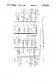
- FIG. 1shows a block diagram of the network interface controller circuit and its connection to both a packet switched system and a circuit switched system;
- FIG. 2shows tables used by the network interface controller and the call processor of the circuit switched system
- FIG. 3shows a call set-up sequence for a data call from a circuit switched system terminal to a packet switched system terminal
- FIG. 4shows a call set-up sequence for a data call from a packet switched system terminal to a circuit switched system terminal
- FIG. 5shows the various message formats used for establishing inter-system communication
- FIG. 6shows the commands utilized by the network access unit (NAU) and the digital line circuit (DLC) subunits of the network interface controller.
- NAUnetwork access unit
- DLCdigital line circuit
- FIG. 1illustrates a network interface controller (NIC) 14, according to the present invention, which interfaces a circuit switched system (CSS) 12 to a packet switched system (PSS) 13.
- the CSSuses a time-division multiplexed (TDM) bus 124 for communications between terminals involved in a voice or a data call.
- TDMtime-division multiplexed
- the PSSuses a packet bus for transmitting data between terminals.
- the CSSincludes a call processor 123 connected over TDM bus 124 to a plurality of port circuits (PC) 122-1 through 122-J for interfacing voice and/or data terminals 121-1 through 121-J, respectively, to the system.
- PCport circuits
- Port circuit 122-Kprovides access to other circuit switched systems.
- the circuit switched systemmay be, for example, an AT&T System 75 Digital Communication System as described in the article entitled “System 75: Communications and Control Architecture" by L. A. Baxter et al, published in the AT&T Technical Journal, Jan. 1985, page 153 et seq.
- the PSSmay be a well-known local area network, such as an AT&T Starlan network, which includes a group of network access units (NAU) 132-1 through 132-M. Terminals 131-1 through 131-M communicate via NAU 132-1 through 132-M, respectively, to establish calls between themselves over packet (CSMA) bus 133 of the PSS.
- the NAUscompete with each other for access to packet bus 133.
- Packet system interface (PSI) 134provides access to other packet switched systems.
- the operation of the Starlan network NAUis described in "The STARLAN Network Technical Reference Manual" (999-300-208IS), published by AT&T
- the NAUs(132-1-132-M) enable terminals 131-to 131-M to communicate on packet systems to each other.
- the software driver for NAUstypically includes (1) a command interpreter to interact with the terminal using a common language, (2) a macro command expander which breaks down a macro command into a series of commands for the distant terminal, and (3) a response analyzer which reacts to responses from the distant machine, including various kinds of faults and retries.
- the NAUsalso include a contention resolution circuit for determining when the terminal can access CSMA bus 133.
- NIC 14enables a data terminal of CSS 12 to communicate with other terminals of CSS 12 or with a terminal of PSS 13, or viceversa, using single-stage dialing.
- Single-stage dialingeliminates an extra layer of system administration.
- a uniform addressing planassigns terminals on CSS 12 and PSS 13 unique addresses, thereby eliminating address translation for inter-system calls.
- the dialing of a data call on CSS 12is the same whether it is an intra-system or inter-system data call.
- intra-system and inter-system calls on PSS 13can utilize the same uniform dialing plan.
- a data call between originating terminal 121-1 on CSS 12 and destination terminal 131-M on PSS 13would basically be established as follows: Terminal 121-1 dials a data call request to call processor (CP) 123.
- the CP 123checks a terminal location table (201 of FIG. 2) to determine if the destination terminal 131-M is located in CSS 12 or PSS 13. Since destination terminal 131-M is located on PSS, CP 123 forwards the call request to NIC 14.
- the NIC 14acts like a terminal on PSS 13 and attempts to complete the data call to destination terminal 131-M. If the data call set-up on PSS 13 is successful, NIC 14 notifies CP 123 accordingly.
- the CP 123selects a data converter (e.g., 145D) for the call and sends an appropriate message back to the originating terminal 121-1.
- the data transmission path for the established data callincludes originating terminal 121-1, port circuit 122-1, TDM bus 124, T/R 147, data bus 154, NPE 152, data converter 145D, NAU bus 146, CSMA interface controller 141, NAU 132-1 and destination terminal 131-M.
- NIC 14If the call set-up fails on PSS 13, NIC 14 notifies CP 123 of the failure and CP 123 terminates the call attempt and signals originating terminal 121-1 accordingly.
- call processor 123utilizes its terminal location table 201 to determine that the data call is an intra-system call. That is, both originating terminal 121-1 and destination terminal 121-J are located in system CSS 12.
- a data call between an originating terminal 131-1 on PSS 13 to a destination terminal 121-J on CSS 112basically proceeds as follows: Terminal 131-1 sends a data call request to NIC 14 which checks terminal location table (203 of FIG. 2) to determine the location of destination terminal 121-J. Note, table 203 contains only valid CSS 12 terminal address information. Since destination terminal 121-J is located in CSS 12, NIC 14 reformats the request and forwards it to CP 123 of CSS 12. NIC 14 then selects an idle data converter (e.g., 145A) to initiate the call. The call processor CP 123 tries to complete the call if destination terminal 121-J is available for a call.
- Terminal 131-1sends a data call request to NIC 14 which checks terminal location table (203 of FIG. 2) to determine the location of destination terminal 121-J. Note, table 203 contains only valid CSS 12 terminal address information. Since destination terminal 121-J is located in CSS 12, NIC 14 reformats the request and forwards it to CP 123
- the CP 123assigns talk and listen time slots on TDM bus 124 for data communications between destination terminal 121-J and NIC 14. Then NIC 14 sends a confirmation back to originating terminal 131-1 to complete the data call. Data communication then proceeds from originating terminal 131-1, NAU 132-1, CSMA interface controller 141, data converter 145A, NPE 152, transceiver 147 and port circuit 122-J to destination terminal 121-J.
- CP 123If the destination terminal 121-J on CSS 12 is not ready to accept a call, CP 123 signals NIC 14 which sends a call-denied message to the originating terminal to terminate the data call.
- a terminal on PSS 13communicates call control information to CP 123 on CSS 12.
- An originating terminale.g., 131-M
- the NIC 14reformats the request and forwards the request to CP 123.
- the CP 123recognizes that the request is a control information request and not a data call request.
- the CP 123 and the originating terminalthen exchange control information through NIC 14. This control information exchange occurs over the control channel of the TDM bus 124, transceiver 147, SAKI 148, DLC bus 153, dualport memory 155, CSMA interface controller 141 and NAU 132-M to originating terminal 131-M.
- the DLC subunit of NIC 14includes NPE 152, DLC controller 151, ROM 150, RAM 149, SAKI 148 and transceiver 147, all connected via DLC bus 153 and data bus 154 as shown in FIG. 1.
- the DLC subunitis and functions essentially as another port circuit (e.g., 122-1) of CSS 12. Thus, calls can be established between any of the terminals 121-1 to 121-J and DLC over TDM bus 124.
- Bus transceiver 147interfaces the port circuit 200 to TDM bus 124.
- the time-slot information from TDM bus 124includes control information and data.
- the datamay be either digitized pulse code modulation (PCM) voice samples or digital data. These data are converted to and from the TDM format by network processing element (NPE) 152.
- NPEnetwork processing element
- a control interface SAKI 148connects to DLC controller 151 via DLC bus 153.
- the control interface SAKI 148receives and transmits control information over the TDM bus 124 and the DLC controller 151 transmits and receives information over data bus 154.
- the DLC controller 151, ROM 150 and RAM 149 circuitsperform functions common to all port circuits and specific-application functions which are unique to a particular type of port circuit.
- the DLC controller 151carries out the port circuit's particular function and enables it to communicate with system call processor 123.
- a useroriginates a call by going off-hook on his/her terminal (e.g., 121-1). This change is detected by a port circuit (122-1) and an off-hook message is sent to the call processor 123. On receiving this message, the resources for processing this call are allocated and messages are sent for giving dial prompt to the user.
- his/her terminale.g., 121-1
- This changeis detected by a port circuit (122-1) and an off-hook message is sent to the call processor 123.
- the resources for processing this callare allocated and messages are sent for giving dial prompt to the user.
- the call processing softwareinterprets each digit entered by the user and routes the call to the termination station via TDM bus 124 when all the digits have been entered.
- the format for this TDM messageis 501.
- the callis signaled to the terminating user with a ringing message, and the call progress is indicated to the originating user with a ringback message.
- call processor 123removes the ringing and ringback messages with a ringback-removed message and establishes a talk/listen path between the originator and the terminator.
- the talk/listen pathutilizes separate time slots for the transmit and receive paths as assigned by call processor 123.
- the call processing softwaretears down the circuit connection and deallocates all the resources associated with the call.
- PSSPacket Switched System
- the NAU1 subunit of NIC 14includes NAU1 controller 144, ROM 143, RAM 142, and CSMA interface controller 141 connected via NAU1 bus 146.
- the NAU1 subunitfunctions similar to another network access unit NAU (e.g., 132-1).
- NAUnetwork access unit
- Communication between NAUs and NAU1utilize the PSS message format 530.
- This message 530uses the data link level protocol of the well-known International Standard Organization (ISO) protocol. This level of protocol provides administration and error detection for data transport between network access units (NAU) of PSS 13.
- ISOInternational Standard Organization
- NAU1acts like just another network access unit (NAU) of PSS 13.
- the data link levelincludes two sublayers, media access control (MAC) 531 and logical link control (LLC) 540.
- the MAC 531includes sync preamble 532, start-of-frame delimiter 533, destination address 534, source address 535, length field 536 for data field 537, packet padding to achieve minimum packet size 538 and frame check sequence 539.
- Data field 537contains the LLC sublayer 540 address.
- Destination address 534is used to identify the destination station on PSS 13.
- Source address 535identifies NIC 14 as the sending location.
- the LLC sublayerincludes destination service access point 541, source service access point 542, control word 543 and data field 548.
- the data field 548contains TRNS address 544.
- the present embodimentdoes not utilize the network layers of the ISO protocol.
- the transport layer level of the ISO protocolis illustrated by TRNS 544.
- the TRNS layerprovides connectionless (datagram) and connection (virtual circuit) oriented grades of service for data transfer. In both types, the addressing information is conveyed for selection of the endpoints following a particular level 2 MAC 531 address.
- the TRNS layer 544includes PID encodings 545, DEST -- ID 546 (which is the DEST -- ID in INFO 513), SOURCE -- ID 547 (which is the SOURCE -- ID in INFO 513) and information 549 to be conveyed to the destination.
- virtual circuitsare used for data calls between terminals of PSS 13 and terminals of CSS 12.
- the datagram serviceis used according to another feature of the present invention for sending call control messages from a terminal on PSS 13 to call processor 123. This will be described in a later section of this application.
- connection-oriented grade of servicewhich provides a terminal-to-terminal virtual circuit connection.
- the call control packetsinclude the call request (CR), call confirm (CC), call disconnect (CD) commands, etc.
- a call requestis used to request the establishment of a virtual circuit connection between, for example, CSMA interface controller 141 and destination address NAU 132-1.
- the data transfer packetsinclude control only (CO), mixed data (MD), and data only (DO) to communicate, respectively, control messages, control and data, and blocks of user data.
- COcontrol only
- MDmixed data
- DOdata only
- a call disconnect (CD) commandis used to terminate the call.
- communication between NAU1 and DLC subunits of NIC 14utilize dual-port memory 155 for control messages and data converters 145A-145D for data transfers.
- Dual-port memory 155operates in the well-known manner to transfer these control messages 510.
- data converters 145A-145Dinclude a first-in-first-out (FIFO) and control circuit which enable information in packet form to be received from NAU1 and converted into the TDM format for DLC.
- data converters 145A-145Dalso package TDM format data from DLC for transmission in packet form to NAU1.
- the data converterencodes a byte of data in high-level data link control (HDLC) format and transmits the converted data on the TDM bus 124, and decodes the data received from the TDM bus into data bytes directly readable by CPU 123.
- HDLChigh-level data link control
- NAU1/DLC messages 510are used for communication between NAU1 controller 144 and DLC controller 151 which takes place via dual-port memory 155.
- Message 510includes a command field 511, size field 512, and information field 513.
- the command fieldcontains two bytes, 514 and 515. This field is loaded by the command sender and unloaded by command receiver. Hence, for a call initiated by CSS, CSS is the command sender and PSS is the command receiver, and vice-versa.
- the size field 512contains the length in bytes of the information field 513.
- the information fieldincludes any appropriate information required by the command stored in the command field 514.
- Control communications between subunits NAU1 and DLCutilize commands issued through dual-port memory 155 one at a time.
- the command senderchecks that command field 511 is zero. If the command field is zero, any parameters associated with the command are written into the information field 513 and the size data written into size field 512. The command information is written into the command field last. A nonzero value in the command field indicates to the command receiver that the message 510 is completely written and ready to be used. After receiving NAU1/DLC message 510, the command receiver clears the command field 511 indicating that the command is being processed and the next command may be given.
- DLC controller 151is the command sender, it sends originate call command 601 in the format shown in message 510 to the command receiver, NAU1 controller 144.
- NAU1 controller 144communicates the information to CSMA interface controller 141 which then formats the information into the PSS message shown in 530 for transmission to the destination terminal on PSS 13.
- Command 601such as CALL -- CSS is used.
- Command 601is formatted as shown in message 510 except that 515 would be CALL -- CSS and 513 includes the destination number (DEST -- ID) and source number (SOURCE -- ID) but does not include converter device (DEV -- NO) information (since that has yet to be determined by CSS 12).
- the possible responses from DLCinclude call answered 629, call busy 630, converter unavailable 631 and call denied 632. All of these command responses identify the source and destination numbers.
- Call answeredmeans that CSS 12 has answered the call. CSS 12 includes a DEV -- NO in the command response since one has been assigned.
- Call busymeans that the destination terminal is busy.
- Converter unavailablemeans that all converter devices (145A-145D) are in use or reserved by DLC and hence no data communication is possible at this time. Converter devices are reserved each time a data call request is received by call processor 123 from a terminal or either system PSS or CSS. However, a DEV -- NO is only assigned and returned in a command response when a call is answered 609.
- a pending data callis aborted using the abort command shown in 602.
- This abort command 602issued from NAU1 when it received no response from DLC for a predetermined period of time after the originate call command 601 was sent.
- DLCterminates the call set-up attempt and sends an error command 633 to NAU1.
- NAU1When a data call is to be terminated, NAU1 sends a disconnect call command 603 to DLC identifying the destination and source numbers. DLC returns an error command 633 if no such call connection exists. If a call connection exists, no response is required from the DLC and the call is taken down.
- NAU1When NAU1 detects an unexpected/error condition, it reports the error to DLC using diagnostic command 604. DLC forwards this error message to call processor 123 to provide an error logging capability.
- NAU1receives control messages which are identified by the control headers in the data frame received from data converters (145A-145D). NAU1 does not interpret these control messages but rather forwards the entire frame to DLC using control message 605. The size of the control message is calculated by subtracting one from the value of the size field (SIZ).
- the process of making a call from a terminal of CSS 12 to a terminal of PSS 13generally utilizes the same commands and receives the same command responses as the calls initiated from PSS 13 to CSS 12 as described in the preceding paragraphs.
- the origination of a call from a terminal of CSS 12 to a terminal of PSS 13uses command 621.
- Responses from PSS 13include only call answered 609 and call denied 612; no call busy 610 or device unavailable 611 is utilized.
- Disconnecting a callutilizes command 623 with no response being necessary unless no such call connection existed, in which case an error response 613 is made.
- a CSS 12 call attemptis aborted using command 622. This command terminates the call set-up attempt and clears the previous call originate command 621. NAU1 responds with a command error 613 if no such call set-up attempt exists between the destination and source numbers.
- Control message 625is used to send control messages from DLC of NIC 14 to a remote port circuit (e.g., 122-1) of CSS 12.
- NAU1identifies the control message as such from the control header (TX-DCP).
- NAU1upon receiving this control command inserts the entire message into the data stream going through the designated converter device (DEV -- NO) to the identified port circuit.
- DCP control messagesare EIA updates and data module handshake messages. There is no command response message from NAU1 in response to control message 625.
- the DLC download command 626enables call processor 123 of CSS 12 to download terminal location table 203 to NAU1.
- this tableindicates the valid terminal numbers of system CSS 12.
- groups of ten terminalsare listed, thereby reducing the size of table 201.
- the terminal group numberis listed in table 201, all members of that group are also located on system CSS 12.
- the converter configuration command 627is used by DLC after a successful handshake between the originating source terminal of CSS 12 and the destination terminal of PSS 13.
- DLCsends configuration information to set up the proper data transfer baud rate on the assigned converter device (e.g., 145A).
- This commandalso enables NAU1 to start transferring data received from the terminal on PSS 13 to the terminal on CSS 12. Data received from PSS 13 prior to this command is buffered in the assigned converter device. There is no command response message due from NAU1 in response to this configuration command.
- the DLCis responsible for checking the sanity of NAU1.
- the sanity check command 628is utilized periodically to accomplish this function.
- the NAU1must respond with the check done command response 614 within a predetermined period of time. Otherwise, DLC considers the NAU1 unacceptable and both DLC and NAU1 enter a reset sequence. During such a reset sequence, all calls on the network interface controller (NIC) are terminated.
- NICnetwork interface controller
- NAU1 subunit of NIC 14operates in either a gateway mode or a bridge mode.
- the PSS universal receive protocol (URP)is terminated on NAU1.
- the bridge modethe URP protocol is preserved across the two systems.
- Source terminal 121-1 on CSSdesires to set up a data call to destination terminal 131-1 on PSS using a gateway mode.
- the user at terminal 121-1establishes a data call by dialing the extension number of the destination terminal 131-1 in the normal manner (301) as previously described.
- Call processor 123 of CSSreceives the dialed extension number and checks terminal location table 201 to determine whether the port associated with the destination terminal extension is located in system PSS or CSS.
- Terminal location table 201is located in both CP 123 and in RAM 142 of NAU1.
- the terminal location table 201 in CP 123is generated by the system CSS administrator and contains a list of all dialable terminal numbers on CSS 12. This list is downloaded to RAM 142 of NAU1 from CP 123 when CSS is initialized.
- Terminal location table 203is constructed based upon this list.
- call processor 123determines from table 201 that destination terminal 131-1 is located on PSS (202). Call processor 123 then sends both the destination terminal number 131-1 and the source or originating terminal number 121-1 over TDM bus 124 using the message shown in 501.
- Message 501includes a header 502 to identify whether port circuit 122-1 to 122-K or DLC is to receive the information.
- the DLC addressis inserted in header 502.
- Call processor 123also checks data converter table 202 for an available data converter device 145A-145D. Call processor 123 then sends a ringer-on downlink message to DLC to indicate an incoming call. Upon receiving the ringer-on message, DLC sends an ID request message uplink message to call processor 123. Call processor then sends message 501 with data converter device number in 503, the destination terminal extension inserted in 504 and the source terminal extension in 505.
- Message 501is received by SAKI 148 via transceiver 147 and forwards the information over bus 153 to DLC controller 151.
- DLC controller 151reformats the content of message 501 into message format 510.
- the destination numberis needed by network interface controller NIC to set up the call to the destination terminal on PSS 13.
- the source numberis required by the PSS protocol for call set-ups. Since NIC has only one PSS physical address, the source number is used to identify NIC as the calling PSS port. The source number can also be used by the application as the basis on which to accept or reject the call. Although NIC can use a dummy source number for port identifications, the receiver cannot use it for caller identification.
- the originate call command 621 to PSS 13is formatted as shown in message 510 to identify, in 513, the destination terminal number, source terminal number and converter device number. During step 302, this originate call command enters dual-port memory 155 where it is retrieved by NAU1 controller 144. In step 303, NAU1 controller causes CSMA interface controller 141 to start a call request on PSS 13. The CSMA interface controller reformats the call request from message format 510 into PSS message format 530.
- the call requestincludes a call inquiry command to NAU 132-1 to get the physical address which corresponds to the destination number.
- NAU 132-1recognizes its destination number and sends a call inquiry response specifying its physical address to CSMA controller 141.
- CSMA controller 141then sends a call request to NAU 132-1 and requests to place a call on CSMA bus 133 using physical address.
- NAU 132-1responds with either a call confirm message or a call disconnect message.
- NAU1 controllerconverts the call confirm message into a command response message format 520.
- the message 520is then sent via dualport memory 155 to DLC and via SAKI 148 is converted to an off-hook response in format 501 and sent to call processor 123 (step 304A).
- Call processor 123then assigns time slots to the end points for data communication.
- a data module handshakeis made to ensure a compatible connection between NIC 14 and terminal 121-1. For example, the data transfer rate has to match between NIC 14 and terminal 121-1. Thereafter, the call set-up is completed in step 306.
- NIC 14 and terminal 131-1exchange URP initialization INIT handshake to determine URP protocol parameters (such as buffer sizes).
- URP protocol parameterssuch as buffer sizes
- This data transferoccurs via NAU 132-1, CSMA interface controller 141, RAM 142, NAU1 controller 144, converter device 145A, NPE 152, transceiver 147 and port circuit 122-1. Note that the control messages of the data transmission get back to DLC controller 151 from the converter device 145A via NAU system bus 146 and dual-port memory 155.
- Data transfer on CSSoccurs in the predetermined time slot, one or more bytes of data per frame, between terminal 121-1 and NIC 14.
- Each frameis encoded in HDLC which has a header and a CRC error code sequence.
- Converter device 145Adoes a CRC error check and checks the framing and then strips off the CRC error sequence.
- the output of converter device 145Ais the header and data which is read by NAU1 controller 144.
- NAU1 controller 144then appends the data to a destination number, logical channel number, and sends it via RAM 142 to CSMA interface controller 141.
- CSMA interface controller 141collects the data to form a packet and then transmits the packet over CSMA bus 133 to NAU 132-1.
- a bridge mode data call from an originating terminal 121-1 on CSS 12 to terminal 131-1 on PSS 13proceeds as follows.
- the difference between a bridge mode data call and a gateway mode data callis that in bridge mode, the originating terminal 121-1 is responsible for call set-up on PSS 13.
- the NIC 14completes the call set-up on PSS 13.
- NIC 14plays the role of data translator in this case. It converts the data between the format used on PSS and that on CSS.
- terminal 131-M on system PSS 13wants to originate a data call to terminal 121-J on system CSS 12.
- Terminal 131-Mdoes the normal call set-up process on system PSS 13. This includes a call inquiry command from terminal 131-M to NAU1 of NIC 14 to obtain the physical address of NAU1.
- NAU1sends its physical address in a call inquiry response to terminal 131-M.
- Terminal 131-Msends a call request message 401 to NAU1 including the originating extension number (i.e., terminal 131-M extension number) and the destination extension number (i.e., terminal 121-J on system CSS 12).
- the originating terminal extension numberis supplied by the originating station on PSS 13 whereas, on calls originating from CSS 12 terminals, call processor 123 knows the extension number from an internal table (not shown).
- NAU1 controller 144After receiving the call request, NAU1 controller 144 checks terminal location table 201 to determine whether terminal 121-J is located on system PSS 13 or CSS 12. If the destination terminal is on CSS 12, then NAU1 returns a call pending message to terminal 131-M. Note, the source terminal extension number is also used by call processor 123 to determine access restrictions for calls originated on either system PSS 13 or CSS 12.
- NAU1 controller 144sends an originate data call command 601 to DLC including the destination and source number using message format 510.
- DLCconverts the call origination command into the TDM message format 501 and forwards it via SAKI 148, transceiver 147, TDM bus 124 to call processor 123.
- Call processor 123proceeds with the normal call set-up procedure 402 and assigns a time slot associated with one of the converter devices (145A-145D) which is selected for use during this data call.
- Call processor 123confirms the call 403 and sends the time slot number and converter device number via transceiver 147 and SAKI 148 to DLC controller 151.
- DLC controller 151then loads the assigned data converter in converter assignment table 202 in NPE 152 with the time slot number assigned.
- converter 145Ais assigned time slot 2.
- DLC controller 151proceeds with the standard data module handshake 404 with port circuit 122-J associated with destination terminal 121-J. This handshake sequence ensures that NIC 14 knows what operation parameters (e.g., data rate) the CSS 12 destination terminal 121-J needs.
- destination terminal 121-Jgoes to connected mode.
- Call processor 123signals DLC controller 151 to send call answered command 629 in message format 520 to NAU1 controller 144.
- NAU1 controller 144causes CSMA controller 141 to send a standard call confirmation packet to originating terminal 131-M on PSS 13.
- DLC controllerwaits a predetermined time after the successful handshake with destination terminal 121-J for a bridge mode indication (null packet) therefrom.
- DLC controller 151assumes a gateway mode and proceeds with the data call set-up on PSS 13.
- the call set-up procedure on PSS 13includes an initialization handshake between NAU1 controller 144 and NAU 132-M.
- NIC 14converts between the DCP mode of system CSS 12 and the data format to be used on PSS 13.
- Data transfer 405 between originating terminal 131-M of PSS 13 and destination terminal 121-Joccurs via NAU 132-1, CSMA interface controller 141, RAM 142, bus 146, NAU1 controller 144, converter device 145A, NPE 152, transceiver 147 and port circuit 122-J.
- CSMA interface controllerreceives the data packets from originating terminal 131-M and stores them in RAM 142.
- NAU1 controller 144processes the data a byte at a time and sends the data to converter device 145A which encodes the input data into DCP format and then outputs the information to NPE 152.
- NPE 152places the data byte in the correct time slot for transmission over TDM bus 124 to terminal 121-J.
- NAU1 144would then forward the call request message to destination terminal 121-J.
- the data call set-upnow takes place directly between the originating terminal 131-M on PSS 13 and the terminating terminal 121-J on CSS 12.
- call control messagescan be sent from a terminal on PSS 12 to call processor 123.
- this featureutilizes the datagram service (connectionless service) capability provided by the TRNS sublayer 544 of the ISO protocol shown in FIG. 5.
- Datagram serviceis provided by the link layer in which packets of information are not sent over virtual circuits; the destination address is provided in the packet and no explicit acknowledgment is returned.
- a terminal on CSS 12can only exchange call set-up information with the call processor 123. In other words, a terminal can only request to make a call, disconnect a call, put a call on hold, etc.
- a generalized mechanismis provided for the terminals on PSS 13 to communicate with CP 123 through NIC 14.
- a terminale.g., terminal 131-1
- ituses a call inquiry command in format 530 to find out the PSS physical address for NIC 14.
- a specific PID 545is used to indicate that the packet is for CP 123 from a PSS 13 terminal.
- NIC 14in this case acts as a protocol translator to convert data format between PSS and CSS for transmission on the control channel to CP 123.
- the PSS network layer protocolis removed and CSS control channel protocol added.
- End-to-end data integrity and flow controlis not handled by NIC 14. It is up to the end points (i.e., CP 123 and terminal 131-1) to ensure proper data transmission and reception.
- CSS 12may connect via multiple NICs 14 to interface to multiple PSS 13 systems.
- uniform dialingwould require each terminal of each system to have a unique dialable number.
- Terminal location table 201would specify which system contains which terminals.
Landscapes
- Engineering & Computer Science (AREA)
- Computer Networks & Wireless Communication (AREA)
- Signal Processing (AREA)
- Computer Security & Cryptography (AREA)
- Data Exchanges In Wide-Area Networks (AREA)
Abstract
Description
Claims (10)
Priority Applications (5)
| Application Number | Priority Date | Filing Date | Title |
|---|---|---|---|
| US06/843,239US4723238A (en) | 1986-03-24 | 1986-03-24 | Interface circuit for interconnecting circuit switched and packet switched systems |
| CA530602ACA1268845C (en) | 1986-03-24 | 1987-02-25 | Interface circuit for interconnecting circuit switched and packet switched systems |
| EP87103909AEP0238984A3 (en) | 1986-03-24 | 1987-03-17 | An interface circuit for interconnecting circuit switched and packet switched systems |
| JP62068153AJPS62231546A (en) | 1986-03-24 | 1987-03-24 | interface circuit |
| KR1019870002680AKR910003244B1 (en) | 1986-03-24 | 1987-03-24 | Interface circuitry for interconnection of circuit switches and packet switch systems |
Applications Claiming Priority (1)
| Application Number | Priority Date | Filing Date | Title |
|---|---|---|---|
| US06/843,239US4723238A (en) | 1986-03-24 | 1986-03-24 | Interface circuit for interconnecting circuit switched and packet switched systems |
Publications (1)
| Publication Number | Publication Date |
|---|---|
| US4723238Atrue US4723238A (en) | 1988-02-02 |
Family
ID=25289420
Family Applications (1)
| Application Number | Title | Priority Date | Filing Date |
|---|---|---|---|
| US06/843,239Expired - LifetimeUS4723238A (en) | 1986-03-24 | 1986-03-24 | Interface circuit for interconnecting circuit switched and packet switched systems |
Country Status (5)
| Country | Link |
|---|---|
| US (1) | US4723238A (en) |
| EP (1) | EP0238984A3 (en) |
| JP (1) | JPS62231546A (en) |
| KR (1) | KR910003244B1 (en) |
| CA (1) | CA1268845C (en) |
Cited By (34)
| Publication number | Priority date | Publication date | Assignee | Title |
|---|---|---|---|---|
| US4933931A (en)* | 1988-06-17 | 1990-06-12 | Fujitsu Limited | Integrated accounting system |
| US4935894A (en)* | 1987-08-31 | 1990-06-19 | Motorola, Inc. | Multi-processor, multi-bus system with bus interface comprising FIFO register stocks for receiving and transmitting data and control information |
| US5014266A (en)* | 1988-12-28 | 1991-05-07 | At&T Bell Laboratories | Circuit switching system for interconnecting logical links between packet switching networks |
| US5410754A (en)* | 1993-07-22 | 1995-04-25 | Minute Makers, Inc. | Bi-directional wire-line to local area network interface and method |
| US5822522A (en)* | 1992-11-05 | 1998-10-13 | Kabushiki Kaisha Tec | System for transferring data through a communication interface using control information in request data for controlling data receiving rates independent of the CPU |
| US6195345B1 (en) | 1997-12-03 | 2001-02-27 | Ericsson Messaging Systems, Inc. | High capacity multimedia messaging exchanges |
| US6240086B1 (en)* | 1999-10-15 | 2001-05-29 | Texas Instruments Incorporated | Dynamic DSP allocation for universal access to a packet network |
| US6295551B1 (en) | 1996-05-07 | 2001-09-25 | Cisco Technology, Inc. | Call center system where users and representatives conduct simultaneous voice and joint browsing sessions |
| US20010024439A1 (en)* | 1998-10-30 | 2001-09-27 | Edward Morgan | Dynamic DSP allocation for universal access to a packet network |
| US20020040425A1 (en)* | 2000-10-04 | 2002-04-04 | David Chaiken | Multi-dimensional integrated circuit connection network using LDT |
| US20020064152A1 (en)* | 2000-11-28 | 2002-05-30 | Lemley Donald G. | Packet voice gateway |
| US6442169B1 (en) | 1998-11-20 | 2002-08-27 | Level 3 Communications, Inc. | System and method for bypassing data from egress facilities |
| AU758713B2 (en)* | 1998-02-17 | 2003-03-27 | Genesys Telecommunications Laboratories, Inc. | Telephone network interface bridge between data telephony networks and dedicated connection telephony networks |
| US6600733B2 (en)* | 1997-02-06 | 2003-07-29 | Verizon Laboratories Inc. | System for interconnecting packet-switched and circuit-switched voice communications |
| US6614781B1 (en) | 1998-11-20 | 2003-09-02 | Level 3 Communications, Inc. | Voice over data telecommunications network architecture |
| US6636519B1 (en) | 1994-06-09 | 2003-10-21 | Ut Starcom, Inc. | Network access method and network access server therefor |
| US20030223407A1 (en)* | 1993-01-08 | 2003-12-04 | Multi-Tech Systems, Inc. | Computer implemented voice over data communication apparatus and method |
| US6724748B1 (en) | 1998-05-21 | 2004-04-20 | Telefonaktiebolaget Lm Ericsson (Publ) | Intelligent network and packet data network interoperability |
| US6747970B1 (en) | 1999-04-29 | 2004-06-08 | Christopher H. Lamb | Methods and apparatus for providing communications services between connectionless and connection-oriented networks |
| US20040160913A1 (en)* | 1995-10-05 | 2004-08-19 | Kubler Joseph J. | Hierarchical data collection network supporting packetized voice communications among wireless terminals and telephones |
| US6839341B1 (en)* | 1999-06-17 | 2005-01-04 | Oki Electric Industry Co., Ltd. | Device capable of accommodating existing voice terminals |
| US20050033581A1 (en)* | 2001-02-16 | 2005-02-10 | Foster Mark J. | Dual compression voice recordation non-repudiation system |
| US20050249205A1 (en)* | 1997-12-15 | 2005-11-10 | Tellabs Research Limited | Telecommunication systems |
| US20060080106A1 (en)* | 2000-06-08 | 2006-04-13 | Theodore Calderone | System and method of voice recognition near a wireline node of a network supporting cable television and/or video delivery |
| US20060092831A1 (en)* | 2004-11-01 | 2006-05-04 | Tekelec | Methods, systems, and computer program products for substitution of card-based telephony bearer channel switch modules in a manner that preserves stable calls |
| US20060239438A1 (en)* | 2000-05-04 | 2006-10-26 | Telemaze Llc | Tandem Access Controller Within the Public Switched Telephone Network |
| US20070047562A1 (en)* | 2005-08-31 | 2007-03-01 | Motorola, Inc. | Method and apparatus for cross paging a multi network communication system |
| US7336649B1 (en) | 1995-12-20 | 2008-02-26 | Verizon Business Global Llc | Hybrid packet-switched and circuit-switched telephony system |
| WO2008027065A1 (en)* | 2006-08-31 | 2008-03-06 | Syniverse Technologies, Inc. | Cellular-to-voip call establishment systems, methods, devices, and computer software |
| US20100058234A1 (en)* | 2008-08-29 | 2010-03-04 | Contactual, Inc. | Networked contact center user interface |
| US20110013622A1 (en)* | 1993-12-15 | 2011-01-20 | Hitachi, Ltd. | Voice communication system and voice communication method |
| US8938062B2 (en) | 1995-12-11 | 2015-01-20 | Comcast Ip Holdings I, Llc | Method for accessing service resource items that are for use in a telecommunications system |
| US9191505B2 (en) | 2009-05-28 | 2015-11-17 | Comcast Cable Communications, Llc | Stateful home phone service |
| US9338190B2 (en) | 1994-10-11 | 2016-05-10 | Aip Acquisition Llc | System and method for managing multimedia communications across convergent networks |
Families Citing this family (1)
| Publication number | Priority date | Publication date | Assignee | Title |
|---|---|---|---|---|
| CA2001861C (en)* | 1988-12-28 | 1996-12-17 | Bruce Merrill Bales | Circuit switching system for interconnecting logical links between packet switching networks |
Citations (4)
| Publication number | Priority date | Publication date | Assignee | Title |
|---|---|---|---|---|
| US4313036A (en)* | 1980-02-19 | 1982-01-26 | Rolm Corporation | Distributed CBX system employing packet network |
| US4486878A (en)* | 1981-09-23 | 1984-12-04 | U.S. Philips Corporation | Digital telephone exchange with means for processing packet-switched data |
| US4556972A (en)* | 1983-12-27 | 1985-12-03 | At&T Bell Laboratories | Arrangement for routing data packets through a circuit switch |
| US4592048A (en)* | 1984-05-03 | 1986-05-27 | At&T Bell Laboratories | Integrated packet switching and circuit switching system |
Family Cites Families (5)
| Publication number | Priority date | Publication date | Assignee | Title |
|---|---|---|---|---|
| JPS53126202A (en)* | 1977-04-11 | 1978-11-04 | Nec Corp | Composite data exchange system |
| FR2458957B1 (en)* | 1979-06-13 | 1986-02-07 | Telediffusion Fse | TELEINFORMATIC CONCENTRATOR FOR PACKET DATA TRANSMISSION AND SWITCHING NETWORK |
| JPS58114646A (en)* | 1981-12-28 | 1983-07-08 | Nippon Telegr & Teleph Corp <Ntt> | Controlling system of inter-network connection |
| DE3210439A1 (en)* | 1982-03-22 | 1983-09-22 | Siemens AG, 1000 Berlin und 8000 München | METHOD AND CIRCUIT ARRANGEMENT FOR TRANSMITTING MESSAGE SIGNALS BETWEEN DIFFERENT TRANSMISSION PROCESSES WORKING CENTERS OF A FIRST SWITCHING NETWORK AND A SECOND SWITCHING NETWORK |
| JPS6130148A (en)* | 1984-07-20 | 1986-02-12 | Nec Corp | System for connection between time division telephone exchange network and packet switching network |
- 1986
- 1986-03-24USUS06/843,239patent/US4723238A/ennot_activeExpired - Lifetime
- 1987
- 1987-02-25CACA530602Apatent/CA1268845C/ennot_activeExpired
- 1987-03-17EPEP87103909Apatent/EP0238984A3/ennot_activeWithdrawn
- 1987-03-24JPJP62068153Apatent/JPS62231546A/enactivePending
- 1987-03-24KRKR1019870002680Apatent/KR910003244B1/ennot_activeExpired
Patent Citations (4)
| Publication number | Priority date | Publication date | Assignee | Title |
|---|---|---|---|---|
| US4313036A (en)* | 1980-02-19 | 1982-01-26 | Rolm Corporation | Distributed CBX system employing packet network |
| US4486878A (en)* | 1981-09-23 | 1984-12-04 | U.S. Philips Corporation | Digital telephone exchange with means for processing packet-switched data |
| US4556972A (en)* | 1983-12-27 | 1985-12-03 | At&T Bell Laboratories | Arrangement for routing data packets through a circuit switch |
| US4592048A (en)* | 1984-05-03 | 1986-05-27 | At&T Bell Laboratories | Integrated packet switching and circuit switching system |
Non-Patent Citations (8)
| Title |
|---|
| C. J. Jenny and K. Kummerle, "Distributed Processing Within an Integrated Circuit/Packet-Switching Node," IEEE Transactions on Communications, vol. COM-24, No. 10, Oct. 1976, pp. 1089-1100. |
| C. J. Jenny and K. Kummerle, Distributed Processing Within an Integrated Circuit/Packet Switching Node, IEEE Transactions on Communications, vol. COM 24, No. 10, Oct. 1976, pp. 1089 1100.* |
| G. B. Cicchetti and A. R. Lubarsky, "Hybrid Integrated Digital Network," Proceedings of the World Telecommunication Forum Technical Synposium, 6-8 Oct. 1975, pp. 2.3.7.1-5. |
| G. B. Cicchetti and A. R. Lubarsky, Hybrid Integrated Digital Network, Proceedings of the World Telecommunication Forum Technical Synposium, 6 8 Oct. 1975, pp. 2.3.7.1 5.* |
| J. de Smet and R. W. Sanders, "Pacuit Switching Combines Two Techniques in One Network," Computer Design, Jun. 1976, pp. 83-88. |
| J. de Smet and R. W. Sanders, Pacuit Switching Combines Two Techniques in One Network, Computer Design, Jun. 1976, pp. 83 88.* |
| M. J. Ross, J. H. Gottschalck and E. A. Harrington, "An Architecture for a Flexible Integrated Voice/Data Switch," IEEE 1980, CH1506, pp. 21.6.1-5 (1980 International Conference on Communications, Seattle, Wash., 8-12 Jun. 1980). |
| M. J. Ross, J. H. Gottschalck and E. A. Harrington, An Architecture for a Flexible Integrated Voice/Data Switch, IEEE 1980, CH1506, pp. 21.6.1 5 (1980 International Conference on Communications, Seattle, Wash., 8 12 Jun. 1980).* |
Cited By (89)
| Publication number | Priority date | Publication date | Assignee | Title |
|---|---|---|---|---|
| US4935894A (en)* | 1987-08-31 | 1990-06-19 | Motorola, Inc. | Multi-processor, multi-bus system with bus interface comprising FIFO register stocks for receiving and transmitting data and control information |
| US4933931A (en)* | 1988-06-17 | 1990-06-12 | Fujitsu Limited | Integrated accounting system |
| US5014266A (en)* | 1988-12-28 | 1991-05-07 | At&T Bell Laboratories | Circuit switching system for interconnecting logical links between packet switching networks |
| US5822522A (en)* | 1992-11-05 | 1998-10-13 | Kabushiki Kaisha Tec | System for transferring data through a communication interface using control information in request data for controlling data receiving rates independent of the CPU |
| US7542555B2 (en) | 1993-01-08 | 2009-06-02 | Multi-Tech Systems, Inc. | Computer-based multifunctional personal communication system with caller ID |
| US7082141B2 (en) | 1993-01-08 | 2006-07-25 | Multi-Tech Systems, Inc. | Computer implemented voice over data communication apparatus and method |
| US7082106B2 (en) | 1993-01-08 | 2006-07-25 | Multi-Tech Systems, Inc. | Computer-based multi-media communications system and method |
| US20060153176A1 (en)* | 1993-01-08 | 2006-07-13 | Multi-Tech Systems, Inc. | Computer-based multifunctional personal communication system with caller ID |
| US7092406B2 (en) | 1993-01-08 | 2006-08-15 | Multi-Tech Systems, Inc. | Computer implemented communication apparatus and method |
| US20030223407A1 (en)* | 1993-01-08 | 2003-12-04 | Multi-Tech Systems, Inc. | Computer implemented voice over data communication apparatus and method |
| US5796742A (en)* | 1993-07-22 | 1998-08-18 | U.S. Robotics Corporation | Bi-diredctional wire-line to local area network interface and method |
| US5410754A (en)* | 1993-07-22 | 1995-04-25 | Minute Makers, Inc. | Bi-directional wire-line to local area network interface and method |
| US20110013622A1 (en)* | 1993-12-15 | 2011-01-20 | Hitachi, Ltd. | Voice communication system and voice communication method |
| US6636519B1 (en) | 1994-06-09 | 2003-10-21 | Ut Starcom, Inc. | Network access method and network access server therefor |
| US9338190B2 (en) | 1994-10-11 | 2016-05-10 | Aip Acquisition Llc | System and method for managing multimedia communications across convergent networks |
| US20100118864A1 (en)* | 1995-10-05 | 2010-05-13 | Kubler Joseph J | Hierarchical Data Collection Network Supporting Packetized Voice Communications Among Wireless Terminals And Telephones |
| US20040160913A1 (en)* | 1995-10-05 | 2004-08-19 | Kubler Joseph J. | Hierarchical data collection network supporting packetized voice communications among wireless terminals and telephones |
| US8938062B2 (en) | 1995-12-11 | 2015-01-20 | Comcast Ip Holdings I, Llc | Method for accessing service resource items that are for use in a telecommunications system |
| US7336649B1 (en) | 1995-12-20 | 2008-02-26 | Verizon Business Global Llc | Hybrid packet-switched and circuit-switched telephony system |
| US20090135811A1 (en)* | 1995-12-20 | 2009-05-28 | Verizon Business Global Llc | Hybrid packet-switched and circuit-switched telephony system |
| US8780890B2 (en) | 1995-12-20 | 2014-07-15 | Verizon Patent And Licensing Inc. | Hybrid packet-switched and circuit-switched telephony system |
| US6295551B1 (en) | 1996-05-07 | 2001-09-25 | Cisco Technology, Inc. | Call center system where users and representatives conduct simultaneous voice and joint browsing sessions |
| US6600733B2 (en)* | 1997-02-06 | 2003-07-29 | Verizon Laboratories Inc. | System for interconnecting packet-switched and circuit-switched voice communications |
| US6931001B2 (en) | 1997-02-06 | 2005-08-16 | Verizon Laboratories Inc. | System for interconnecting packet-switched and circuit-switched voice communications |
| US6195345B1 (en) | 1997-12-03 | 2001-02-27 | Ericsson Messaging Systems, Inc. | High capacity multimedia messaging exchanges |
| US7974274B2 (en)* | 1997-12-15 | 2011-07-05 | Tellabs Research Limited | Telecommunication systems |
| US20050249205A1 (en)* | 1997-12-15 | 2005-11-10 | Tellabs Research Limited | Telecommunication systems |
| US8761177B2 (en) | 1997-12-15 | 2014-06-24 | Tellabs Emea Holdings Limited | Telecommunication systems |
| AU758713B2 (en)* | 1998-02-17 | 2003-03-27 | Genesys Telecommunications Laboratories, Inc. | Telephone network interface bridge between data telephony networks and dedicated connection telephony networks |
| US6724748B1 (en) | 1998-05-21 | 2004-04-20 | Telefonaktiebolaget Lm Ericsson (Publ) | Intelligent network and packet data network interoperability |
| US20010024439A1 (en)* | 1998-10-30 | 2001-09-27 | Edward Morgan | Dynamic DSP allocation for universal access to a packet network |
| US8953585B2 (en) | 1998-11-20 | 2015-02-10 | Level 3 Communications, Llc | System and method for bypassing data from egress facilities |
| US20030198216A1 (en)* | 1998-11-20 | 2003-10-23 | Level 3 Communications, Inc. | System and method for bypassing data from egress facilities |
| US8693347B2 (en) | 1998-11-20 | 2014-04-08 | Level 3 Communications, Llc | Voice over data telecommunications network architecture |
| US8416769B2 (en) | 1998-11-20 | 2013-04-09 | Level 3 Communications, Llc | System and method for bypassing data from egress facilities |
| US8270421B2 (en) | 1998-11-20 | 2012-09-18 | Level 3 Communications, Llc | Voice over data telecommunications network architecture |
| US20100296508A1 (en)* | 1998-11-20 | 2010-11-25 | Lewis Shawn M | System and method for bypassing data from egress facilities |
| US7200150B2 (en) | 1998-11-20 | 2007-04-03 | Level 3 Communications, Inc. | System and method for bypassing data from egress facilities |
| US20080013531A1 (en)* | 1998-11-20 | 2008-01-17 | Elliott Isaac K | Voice over data telecommunications network architecture |
| US8089958B2 (en) | 1998-11-20 | 2012-01-03 | Level 3 Communications, Llc | Voice over data telecommunications network architecture |
| US8085761B2 (en) | 1998-11-20 | 2011-12-27 | Level 3 Communications, Llc | Voice over data telecommunications network architecture |
| US20080025294A1 (en)* | 1998-11-20 | 2008-01-31 | Elliott Isaac K | Voice over data telecommunications network architecture |
| US20040022237A1 (en)* | 1998-11-20 | 2004-02-05 | Level 3 Communications, Inc. | Voice over data telecommunications network architecture |
| US8036214B2 (en) | 1998-11-20 | 2011-10-11 | Level 3 Communications, Llc | Voice over data telecommunications network architecture |
| US7564840B2 (en) | 1998-11-20 | 2009-07-21 | Level 3 Communications, Llc | Voice over data telecommunications network architecture |
| US6614781B1 (en) | 1998-11-20 | 2003-09-02 | Level 3 Communications, Inc. | Voice over data telecommunications network architecture |
| US6442169B1 (en) | 1998-11-20 | 2002-08-27 | Level 3 Communications, Inc. | System and method for bypassing data from egress facilities |
| US6747970B1 (en) | 1999-04-29 | 2004-06-08 | Christopher H. Lamb | Methods and apparatus for providing communications services between connectionless and connection-oriented networks |
| US6839341B1 (en)* | 1999-06-17 | 2005-01-04 | Oki Electric Industry Co., Ltd. | Device capable of accommodating existing voice terminals |
| US6240086B1 (en)* | 1999-10-15 | 2001-05-29 | Texas Instruments Incorporated | Dynamic DSP allocation for universal access to a packet network |
| US7411939B1 (en) | 2000-03-21 | 2008-08-12 | Alcatel Lucent | Methods and apparatus for providing communications services between connectionless and connection-oriented networks |
| US8155298B2 (en) | 2000-05-04 | 2012-04-10 | Telemaze Llc | Tandem access controller within the public switched telephone network |
| US20080075262A1 (en)* | 2000-05-04 | 2008-03-27 | Telemaze Llc | Branch Calling and Caller ID Based Call Routing Telephone Features |
| US8848894B2 (en) | 2000-05-04 | 2014-09-30 | Focal Ip, Llc | Tandem access controller within the public switched telephone network |
| US8718252B2 (en) | 2000-05-04 | 2014-05-06 | Focal Ip, Llc | Tandem access controller within the public switched telephone network |
| US7764777B2 (en) | 2000-05-04 | 2010-07-27 | Telemaze Llc | Branch calling and caller ID based call routing telephone features |
| US20100254376A1 (en)* | 2000-05-04 | 2010-10-07 | Telemaze Llc | Branch calling and caller id based call routing telephone features |
| US7587036B2 (en) | 2000-05-04 | 2009-09-08 | Telemaze Llc | Tandem access controller within the public switched telephone network |
| US8175240B2 (en) | 2000-05-04 | 2012-05-08 | Telemaze Llc | Tandem access controller within the public switched telephone network |
| US20060239438A1 (en)* | 2000-05-04 | 2006-10-26 | Telemaze Llc | Tandem Access Controller Within the Public Switched Telephone Network |
| US8457113B2 (en) | 2000-05-04 | 2013-06-04 | Telemaze Llc | Branch calling and caller ID based call routing telephone features |
| US9083719B2 (en) | 2000-05-04 | 2015-07-14 | Focal Ip, Llc | Controller for the intelligent interconnection of two communication networks, and method of use for same |
| US7324635B2 (en) | 2000-05-04 | 2008-01-29 | Telemaze Llc | Branch calling and caller ID based call routing telephone features |
| US20060239437A1 (en)* | 2000-05-04 | 2006-10-26 | Telemaze Llc | Tandem Access Controller Within the Public Switched Telephone Network |
| US20060239436A1 (en)* | 2000-05-04 | 2006-10-26 | Telemaze Llc | Tandem access controller within the public switched telephone network |
| USRE44326E1 (en) | 2000-06-08 | 2013-06-25 | Promptu Systems Corporation | System and method of voice recognition near a wireline node of a network supporting cable television and/or video delivery |
| US20060080106A1 (en)* | 2000-06-08 | 2006-04-13 | Theodore Calderone | System and method of voice recognition near a wireline node of a network supporting cable television and/or video delivery |
| US7685523B2 (en) | 2000-06-08 | 2010-03-23 | Agiletv Corporation | System and method of voice recognition near a wireline node of network supporting cable television and/or video delivery |
| US20020040425A1 (en)* | 2000-10-04 | 2002-04-04 | David Chaiken | Multi-dimensional integrated circuit connection network using LDT |
| US20020064152A1 (en)* | 2000-11-28 | 2002-05-30 | Lemley Donald G. | Packet voice gateway |
| US8095370B2 (en) | 2001-02-16 | 2012-01-10 | Agiletv Corporation | Dual compression voice recordation non-repudiation system |
| US20050033581A1 (en)* | 2001-02-16 | 2005-02-10 | Foster Mark J. | Dual compression voice recordation non-repudiation system |
| US20060092831A1 (en)* | 2004-11-01 | 2006-05-04 | Tekelec | Methods, systems, and computer program products for substitution of card-based telephony bearer channel switch modules in a manner that preserves stable calls |
| US20070047562A1 (en)* | 2005-08-31 | 2007-03-01 | Motorola, Inc. | Method and apparatus for cross paging a multi network communication system |
| WO2007027547A3 (en)* | 2005-08-31 | 2008-01-24 | Motorola Inc | Method and apparatus for cross paging in a multi-network communication system |
| CN101253719B (en)* | 2005-08-31 | 2015-08-26 | 摩托罗拉移动公司 | For crossing over the method and apparatus of paging in multi-network communication system |
| US8599871B2 (en) | 2005-08-31 | 2013-12-03 | Motorola Mobility Llc | Method and apparatus for cross paging a multi network communication system |
| KR101028312B1 (en)* | 2005-08-31 | 2011-04-11 | 모토로라 모빌리티, 인크. | Method and apparatus for cross paging in multi-network communication system |
| WO2008027065A1 (en)* | 2006-08-31 | 2008-03-06 | Syniverse Technologies, Inc. | Cellular-to-voip call establishment systems, methods, devices, and computer software |
| US7676229B2 (en) | 2006-08-31 | 2010-03-09 | Syniverse Technologies, Inc. | Cellular-to-VoIP call establishment systems, methods, devices, and computer software |
| US20080056235A1 (en)* | 2006-08-31 | 2008-03-06 | Syniverse Technologies, Inc. | Cellular-to-VoIP call establishment systems, methods, devices, and computer software |
| US8972885B2 (en)* | 2008-08-29 | 2015-03-03 | 8X8, Inc. | Networked contact center user interface |
| US9225832B1 (en) | 2008-08-29 | 2015-12-29 | 8X8, Inc. | Networked contact center user interface |
| US20100058234A1 (en)* | 2008-08-29 | 2010-03-04 | Contactual, Inc. | Networked contact center user interface |
| US9531879B1 (en) | 2008-08-29 | 2016-12-27 | 8×8, Inc. | Networked contact center user interface approach |
| US10298767B1 (en) | 2008-08-29 | 2019-05-21 | 8X8, Inc. | Networked contact center user interface approach |
| US10863031B1 (en) | 2008-08-29 | 2020-12-08 | 8X8, Inc. | Networked contact center user interface approach |
| US11736618B1 (en) | 2008-08-29 | 2023-08-22 | 8X8, Inc. | Networked contact center user interface approach |
| US9191505B2 (en) | 2009-05-28 | 2015-11-17 | Comcast Cable Communications, Llc | Stateful home phone service |
Also Published As
| Publication number | Publication date |
|---|---|
| JPS62231546A (en) | 1987-10-12 |
| CA1268845A (en) | 1990-05-08 |
| KR870009571A (en) | 1987-10-27 |
| EP0238984A2 (en) | 1987-09-30 |
| KR910003244B1 (en) | 1991-05-24 |
| CA1268845C (en) | 1990-05-08 |
| EP0238984A3 (en) | 1989-09-27 |
Similar Documents
| Publication | Publication Date | Title |
|---|---|---|
| US4723238A (en) | Interface circuit for interconnecting circuit switched and packet switched systems | |
| JP2679635B2 (en) | LAN connection device | |
| US5220560A (en) | Modem pool system based on a packet communication procedure | |
| US5381415A (en) | Call collision sidestep system for two-way simultaneous calls in an ISDN network | |
| JPH10510687A (en) | Data transmission method | |
| EP0777397A2 (en) | Increasing the capacity of a personal communication service system by utilization of the bridged shared line appearance feature | |
| JP2894319B2 (en) | Mobile data communication system | |
| JP3080901B2 (en) | ISDN service method in multi-way multiplex communication system | |
| JP2812767B2 (en) | Packet terminal device and communication system | |
| EP0869689A2 (en) | Communication system for emergency calls | |
| KR100243481B1 (en) | Truncation Response Message Processing Method according to Delay Compensation Protocol of Integrated Information Communication Network | |
| KR100248666B1 (en) | Master Channel Identification Message Processing Method According to Delay Compensation Protocol of Integrated Communication Network | |
| KR100243480B1 (en) | Init ack message processing method according to delay compensation protocol of isdn | |
| JPH10210171A (en) | ISDN data terminal equipment | |
| JPH0758996B2 (en) | Line configuration method | |
| JP3231809B2 (en) | Switching device and control method thereof | |
| AU773721B2 (en) | Multidirectional multiplex communication system and ISDN point-to-multipoint communication method | |
| KR100243482B1 (en) | Channel Identification Message Processing Method According to Delay Compensation Protocol of Integrated Communication Network | |
| JP2000217136A (en) | Communication system in V5.2 communication system | |
| JP3484668B2 (en) | 1 call 2B channel control method | |
| JP2973275B2 (en) | ISDN broadcast method | |
| KR100248664B1 (en) | Method for processing the information channel require primitive according to the delay equalization protocol in isdm | |
| KR100248665B1 (en) | Process of request primitive to disconnect the call according to delay equalijation protocol in isdn | |
| JPH04223635A (en) | Packet switchboard | |
| JPH0817426B2 (en) | Communications system |
Legal Events
| Date | Code | Title | Description |
|---|---|---|---|
| AS | Assignment | Owner name:AT&T INFORMATION SYSTEMS INC., MIDDLETOWN, N.J. 07 Free format text:ASSIGNMENT OF ASSIGNORS INTEREST.;ASSIGNORS:ISREAL, CHARLES M.;JONES, DAVID C. JR.;YANG, CHENG-JEN;AND OTHERS;REEL/FRAME:004542/0705 Effective date:19860320 | |
| STCF | Information on status: patent grant | Free format text:PATENTED CASE | |
| FEPP | Fee payment procedure | Free format text:PAYOR NUMBER ASSIGNED (ORIGINAL EVENT CODE: ASPN); ENTITY STATUS OF PATENT OWNER: LARGE ENTITY | |
| FPAY | Fee payment | Year of fee payment:4 | |
| FPAY | Fee payment | Year of fee payment:8 | |
| FEPP | Fee payment procedure | Free format text:PAYOR NUMBER ASSIGNED (ORIGINAL EVENT CODE: ASPN); ENTITY STATUS OF PATENT OWNER: LARGE ENTITY Free format text:PAYER NUMBER DE-ASSIGNED (ORIGINAL EVENT CODE: RMPN); ENTITY STATUS OF PATENT OWNER: LARGE ENTITY | |
| FPAY | Fee payment | Year of fee payment:12 | |
| AS | Assignment | Owner name:LUCENT TECHNOLOGIES, INC., NEW JERSEY Free format text:ASSIGNMENT OF ASSIGNORS INTEREST;ASSIGNOR:AT&T CORP.;REEL/FRAME:011658/0857 Effective date:19960329 | |
| AS | Assignment | Owner name:THE CHASE MANHATTAN BANK, AS COLLATERAL AGENT, TEX Free format text:CONDITIONAL ASSIGNMENT OF AND SECURITY INTEREST IN PATENT RIGHTS;ASSIGNOR:LUCENT TECHNOLOGIES INC. (DE CORPORATION);REEL/FRAME:011722/0048 Effective date:20010222 | |
| AS | Assignment | Owner name:LUCENT TECHNOLOGIES INC., NEW JERSEY Free format text:TERMINATION AND RELEASE OF SECURITY INTEREST IN PATENT RIGHTS;ASSIGNOR:JPMORGAN CHASE BANK, N.A. (FORMERLY KNOWN AS THE CHASE MANHATTAN BANK), AS ADMINISTRATIVE AGENT;REEL/FRAME:018590/0287 Effective date:20061130 |