US4723131A - Printhead for ink jet printing apparatus - Google Patents
Printhead for ink jet printing apparatusDownload PDFInfo
- Publication number
- US4723131A US4723131AUS06/906,438US90643886AUS4723131AUS 4723131 AUS4723131 AUS 4723131AUS 90643886 AUS90643886 AUS 90643886AUS 4723131 AUS4723131 AUS 4723131A
- Authority
- US
- United States
- Prior art keywords
- membrane
- boss
- ink
- chamber
- bosses
- Prior art date
- Legal status (The legal status is an assumption and is not a legal conclusion. Google has not performed a legal analysis and makes no representation as to the accuracy of the status listed.)
- Expired - Lifetime
Links
- 238000007641inkjet printingMethods0.000titleclaimsabstractdescription9
- 239000012528membraneSubstances0.000claimsabstractdescription77
- 239000011159matrix materialSubstances0.000claimsdescription7
- 238000002508contact lithographyMethods0.000claimsdescription2
- 238000013022ventingMethods0.000claims2
- 230000008878couplingEffects0.000description4
- 238000010168coupling processMethods0.000description4
- 238000005859coupling reactionMethods0.000description4
- 230000036316preloadEffects0.000description3
- 230000000903blocking effectEffects0.000description2
- 239000000463materialSubstances0.000description2
- 238000007639printingMethods0.000description2
- 229920004943Delrin®Polymers0.000description1
- 125000000218acetic acid groupChemical groupC(C)(=O)*0.000description1
- 230000015572biosynthetic processEffects0.000description1
- 238000004140cleaningMethods0.000description1
- 238000010276constructionMethods0.000description1
- 229920001577copolymerPolymers0.000description1
- 238000007599dischargingMethods0.000description1
- 238000005553drillingMethods0.000description1
- 229920001519homopolymerPolymers0.000description1
- 239000007788liquidSubstances0.000description1
Images


Classifications
- B—PERFORMING OPERATIONS; TRANSPORTING
- B41—PRINTING; LINING MACHINES; TYPEWRITERS; STAMPS
- B41J—TYPEWRITERS; SELECTIVE PRINTING MECHANISMS, i.e. MECHANISMS PRINTING OTHERWISE THAN FROM A FORME; CORRECTION OF TYPOGRAPHICAL ERRORS
- B41J2/00—Typewriters or selective printing mechanisms characterised by the printing or marking process for which they are designed
- B41J2/005—Typewriters or selective printing mechanisms characterised by the printing or marking process for which they are designed characterised by bringing liquid or particles selectively into contact with a printing material
- B41J2/01—Ink jet
- B41J2/135—Nozzles
- B41J2/14—Structure thereof only for on-demand ink jet heads
- B—PERFORMING OPERATIONS; TRANSPORTING
- B41—PRINTING; LINING MACHINES; TYPEWRITERS; STAMPS
- B41J—TYPEWRITERS; SELECTIVE PRINTING MECHANISMS, i.e. MECHANISMS PRINTING OTHERWISE THAN FROM A FORME; CORRECTION OF TYPOGRAPHICAL ERRORS
- B41J2/00—Typewriters or selective printing mechanisms characterised by the printing or marking process for which they are designed
- B41J2/005—Typewriters or selective printing mechanisms characterised by the printing or marking process for which they are designed characterised by bringing liquid or particles selectively into contact with a printing material
- B41J2/01—Ink jet
- B41J2/015—Ink jet characterised by the jet generation process
- B41J2/04—Ink jet characterised by the jet generation process generating single droplets or particles on demand
- B41J2002/041—Electromagnetic transducer
- B—PERFORMING OPERATIONS; TRANSPORTING
- B41—PRINTING; LINING MACHINES; TYPEWRITERS; STAMPS
- B41J—TYPEWRITERS; SELECTIVE PRINTING MECHANISMS, i.e. MECHANISMS PRINTING OTHERWISE THAN FROM A FORME; CORRECTION OF TYPOGRAPHICAL ERRORS
- B41J2/00—Typewriters or selective printing mechanisms characterised by the printing or marking process for which they are designed
- B41J2/005—Typewriters or selective printing mechanisms characterised by the printing or marking process for which they are designed characterised by bringing liquid or particles selectively into contact with a printing material
- B41J2/01—Ink jet
- B41J2/135—Nozzles
- B41J2/14—Structure thereof only for on-demand ink jet heads
- B41J2002/14387—Front shooter
- B—PERFORMING OPERATIONS; TRANSPORTING
- B41—PRINTING; LINING MACHINES; TYPEWRITERS; STAMPS
- B41J—TYPEWRITERS; SELECTIVE PRINTING MECHANISMS, i.e. MECHANISMS PRINTING OTHERWISE THAN FROM A FORME; CORRECTION OF TYPOGRAPHICAL ERRORS
- B41J2202/00—Embodiments of or processes related to ink-jet or thermal heads
- B41J2202/01—Embodiments of or processes related to ink-jet heads
- B41J2202/05—Heads having a valve
Definitions
- This inventionrelates to printheads for ink jet printing apparatus, and more particularly to a printhead of this class having a plurality of jet orifices arranged in a matrix for discharging droplets of ink to print alphanumeric characters or other symbols on a surface moving past the printhead.
- an improved printhead of the class describedwhich has a relatively simple, compact, integrated ink jet orifice structure in which the ink jet orifices may be relatively closely spaced for printing relatively small characters; the provision of such a printhead which is reliable in operation and capable of ink jet printing with accurate, well-defined character formation; the provision of such a printhead which has relatively few moving parts, may be manufactured at relatively low cost, and which is easily dissassembled for cleaning, when necessary; and the provision of such a printhead which is capable of adjustment to compensate for tolerance variations, and for accurate control of the droplets.
- the printhead of this inventionthus comprises a body with a recess in its back face.
- a plurality of bossesextend back from the bottom of the recess with an orifice extending through each boss.
- a flexible membraneis mounted over the recess to form a chamber for ink supplied from a source under pressure. The membrane can engage the back ends of the bosses for closing the back ends of the orifices.
- the bosses and orificesare arranged in a close-spaced matrix.
- Meansis provided to hold the membrane against the back end of each boss and selectively release the membrane to allow it to flex away from the boss to deliver a drop of ink from the chamber to the orifice.
- This meanscomprises a slender, elongate member for each boss, the inner end of each elongate member being aligned with its respective boss and thus being arranged in a close array corresponding to the matrix.
- These release meansare larger than the spacing of the bosses and cannot be aligned therewith, and therefore are arranged in a spread-out array with the elongate members extending from the closely spaced array at their inner ends to the release means in their spread-out array.
- the elongate membersare air tubes
- the release meansare valves.
- Each valveis supplied with air under pressure.
- the airis supplied to the tubes so the pressure holds the membrane against the respective bosses.
- the air supply to the tubeis momentarily cut off, momentarily releasing the membrane and allowing a drop of ink to pass from the chamber to the orifice.
- the elongate membersare flexible wires having heads for pressing against the membrane and the release means are solenoids.
- the solenoidswhen energized, momentarily pull the wire and the respective head away from the membrane, releasing the membrane and allowing a drop of ink to pass from the chamber to the orifice.
- FIG. 1is a view in elevation of one side of a first embodiment of a printhead for an ink jet printing apparatus constructed according to the principles of this invention, with a part of the cowling removed to show the interior;
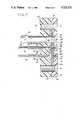
- FIG. 2is an enlarged cross-sectional view of the orifice portion of the printhead, showing the body, membrane, and back plate;
- FIG. 3is a front elevation view of the printhead, with the cowling in place;
- FIG. 4is an enlarged front elevation view of the printhead, with portions broken away to show the back plate, membrane insert, and body;
- FIG. 5is an exploded perspective view of the printhead showing the body, insert, membrane, and back plate;
- FIG. 6is a rear elevation view of the body showing the recess and bosses
- FIG. 7is a front elevation view of a block with a portion broken away to show the interior
- FIG. 8is a partial cross-sectional view of the orifice portion of a second embodiment of a printhead for an ink jet printing apparatus constructed according to the principles of this invention.
- FIG. 9is a top plan view of the printhead.
- FIG. 10is a side elevation view of the printhead.
- FIGS. 1-7A first embodiment of a printhead for an ink jet printing apparatus constructed according to the principles of this invention, indicated generally at 20 in FIGS. 1 and 3, is shown in FIGS. 1-7.
- printhead 20comprises a body 22 having a front face 24 and a rear or back face 26.
- a recess 28is formed in the rear face 26 of body 22.
- a flexible membrane 30extends over recess 28 forming a chamber 32 for ink, supplied to chamber 32 from a source under pressure 34.
- a plurality of posts or bosses 36extend back from the bottom of recess 28, through chamber 32.
- An orifice 38extends through each boss 36, from the back of boss 36 to the front face 24 of body 22.
- membrane 30is engageable with the back ends of bosses 36 for closing the back ends of the orifices 38.
- the orifices 38are closely spaced, arranged in a matrix for non-contact printing of patterns cf data to form characters, such as letters of the alphabet on a target surface moving past the front face 24, adjacent to but spaced from the front face 24, by selective squirting of drops of ink from chamber 32 through the orifices 38 onto the target surface.
- Printhead 20also comprises means for holding membrane 30 against the back ends of bosses 36 to block the flow of ink from chamber 32 through orifices 38, and for selectively releasing membrane 30 to allow it to flex away from the back end of a selected boss 36 for delivery of a drop of ink from chamber 32 through the respective orifice 38.
- this meanscomprises a plurality of relatively slender elongate members 40, one for each boss 36, extending rearwardly from membrane 30, each elongate member 40 being generally aligned at its forward end with its respective boss 36.
- the elongate members 40are thereby in a close-spaced relation, arranged at their inner ends in a closely spaced array corresponding to the matrix of orifices 38.
- Release means 42 at the outer end of each elongate member 40operate via their respective elongate members 40 to release the membrane 30 from their respective bosses 36 for the delivery of a drop of ink from chamber 32 through their respective orifices 38.
- Release means 42are larger than the spacing of the bosses 36 and the orifices 38, and are thereby too large for arrangement of all of the release means 42 directly in line with the bosses 36. Therefore, release means 42 are arranged in an array spread out relative to the bosses 36, the elongate members 40 extending from their relatively closely spaced array at their inner ends to the release means 42 in their spread out array.
- printhead 20comprises a frame 44, and a cowling 46 part of which is removed in FIG. 1.
- Frame 44has a U-shaped bracket 48 for mounting body 22.
- the body 22is preferably made from Delrin, an acetyl homopolymer, or some other suitable material.
- the orifices 38can be formed with lasers or by drilling. As best shown in FIG. 6, the recess 28 in the body 22 has a relatively deeper section 50 that extends adjacent each boss 36.
- An insert 52is positioned in the recess 28 in body 22.
- the insert 52has a hole 54 for receiving each boss 36 and defining an open space 56 adjacent each boss 36.
- Insert 52also has at least one and preferably two inlet holes 58 and 60 for communicating with a source of ink.
- Insert 52 and recess 28cooperate to define a passage 62 between the inlets 58 and 60 and the open spaces 56 around each boss 36.
- this passage 62is formed by the deep portion 50 of recess 28.
- a channelcould be formed in insert 52, extending between the inlet holes 58 and 60 and the holes 54.
- Flexible membrane 30can be die cut or stamped from an ethylene propylene co-polymer or other appropriate material approximately 0.015 to 0.03 inches thick. As shown in FIG. 5, membrane 30 has holes 64 and 66 aligned with holes 58 and 60, respectively.
- a back plate 68 having front face 70 and back face 72is engaged to the body 22, sandwiching membrane 30 therebetween.
- Back plate 68 and body 22are secured with screws 74.
- the front face 70 of back plate 68has a central recessed region 76 for receiving membrane 30.
- a hole 78 aligned with each boss 36,extends through back plate 68.
- Each hole 78is surrounded by raised border 80, the front surface of which engages the membrane 30, sandwiching membrane 30 against the insert 52 and the body 22, forming a chamber 82 behind the membrane 30 aligned with each boss 36.
- a sleeve 84extends from the back face 72 of back plate 68, aligned with each hole 78.
- Holes 86 and 88extend through back plate 68, aligned with the holes 64 and 66 in membrane 30 and with the holes 58 and 60 in insert 52.
- Sleeves 90 and 92extend from the back face 72 of back plate 68 from holes 86 and 88, respectively.
- the elongate members 40comprise air tubes 94.
- the inner ends of air tubes 94fit over the sleeves 84.
- the outer ends of air tubes 94are connected to release means 42.
- the release means 42comprise electrically operated air valves 96.
- Each valve 96has electric leads 98 by which valve 96 can be operated between an unenergized position in which a first port 100 is connected to a common port 102, and an energized position in which a second port 104 is connected to common port 102.
- a tube 106extends from each common port 102 and fits over a sleeve 108 extending through a block 110.
- the outer ends of air tubes 94are fit over these sleeves 108 at the front of block 110.
- each valve 96is connected to a source of air under pressure, so that when valves 96 are in their unenergized position air under pressure is supplied through valves 96 to air tubes 94 and thereafter to the chamber 82 at the back of membrane 30.
- a tube 114extends from each first port 100 and fits over a sleeve 116 extending from the rear of block 110.
- Each sleeve 116communicates with chamber 118 in block 110.
- Chamber 118is supplied with air under pressure by two hoses 120 and 122 connected to opposite sides of block 110 and communicating with chamber 118 therein.
- the other ends of hoses 120 and 122are connected via T-shaped connector 124 to air hose 126.
- Air hose 126extends to a conector 128 at the back of frame 44.
- a hose 130extending to a source of air under pressure, is fitted over connector 128.
- valve 96The second port 104 of valve 96 is open to the atmosphere so that when valve 96 is in the energized condition, the air tubes 94 and thus the chamber 82 at the back of the membrane 30 are vented to the atmosphere.
- the leads 98 of the valves 96terminate in female plugs 132, which fit over pins (not shown) on a board 134.
- the pinsare connected via wires (not shown) to cable 140 extending to a controller that generates the appropriate signals to create the desired characters.
- Ink supply source 34comprises a hose 142 fitted over sleeve 90.
- the hose 142is provided with check valve 144 and a filter 146.
- the hose 142is connected to coupling 148 at the rear of frame 44.
- a hose 150is fitted over sleeve 92 and extends rearwardly.
- Hose 150is connected to coupling 152 at the rear of frame 44.
- a source of ink under pressurecan be connected to couplings 148 and 152.
- Inkis supplied from the source, passes through coupling 148, through hose 142, through filter 146 and check valve 144, through inlet hole 86. The ink then travels through passage 62 to the open spaces 56 adjacent each boss 36.
- Airis supplied from a source, through hose 130, through hose 126, to T-shaped connector 124 where it passes through hoses 120 and 122 to chamber 118 in block 110.
- the airpasses though sleeve 116 to hoses 114, to port 100 of valve 96.
- the airpasses through the valves 96, out the common ports 102, through tubes 106, sleeves 108, to tubes 94.
- the airis then conducted to chambers 82, where the air pressure acts against the back of membrane 30 to hold membrane 30 against the back ends of the bosses 36, blocking the orifices 38.
- the air pressureis in the range between about 5.5 and about 8 p.s.i.
- the ink pressureis in the range between about 2 and about 6 p.s.i.
- the systemis then operated and adjusted to obtain the desired print quality.
- the ink pressureis adjusted to obtain the desired dot size.
- the air pressureis adjusted for clear printing. If the air pressure is too low, extra dots will be formed, if the air pressure is too high, dots in some of the characters may not be formed.
- the air pressuremust be adjusted between these two limits which is different for each ink pressure setting.
- the controllersends the appropriate signals via cable 140 through pins on board 134.
- the signalsare conducted via plugs 132 to the leads of the appropriate valves 96, to momentarily energize those valves.
- a valve 96When a valve 96 is in its energized state, air cannot pass into the port 100 and out the common port 102. Instead, port 104 is conected to common port 102. This allows the pressure in chamber 82 to vent through port 104, allowing membrane 30 to flex rearwardly, allowing ink in the open space 56 around each boss 36 to squirt out the orifice 38.
- a second embodiment of a printhead for an ink jet printeris indicated generally as 200 in FIGS. 9 and 10.
- Print head 200is similar to printhead 20, with like parts being identified with the same numerals. However, the elongated means 40 and release means 42 in printhead 200 are different from the air hoses 94 and valves 96 of printhead 20.
- each means 40comprises a head 202 slideably mounted in bores 204 in back plate 68.
- Heads 202are sized and positioned so that they can impinge on the back of membrane 30, holding it against the backs of bosses 36, blocking orifices 38.
- a wire 206extends rearwardly from each head 202. The head is enlarged relative to the wire.
- Wires 206are each slideably mounted in a sleeve 208. The front end of sleeve 208 is engaged in support block 210. The rear end of sleeve 208 is engaged in block 212.
- Release means 42comprise solenoids 214 connected by leads 215 to a controller. Each wire 206 is connected to the plunger (not shown) of one of the solenoids.
- a threaded projection 216extends from the rear of each solenoid. The projections 216 are secured to vertical webs 218 as with nuts 220.
- a coil spring 222extends between each web 218 and the back of its associated solenoid 214. Nut 220 can be tightened to draw the solenoid rearwardly against the force of spring 222, or nut 220 can be loosened to allow solenoid to be biased forward by spring 222. The position of each head 202 is thereby adjustable to preload the membrane with a compressive force and to compensate for tolerance variations.
- each solenoidcontaining a spring that biases the plunger and associated wire forward relative to the solenoid. Because of the preload, the heads apply pressure against the membrane which when released causes the membrane to spring away from the bosses, mechanically assisting the pressurized ink in moving the membrane out of engagement with the bosses.
- the amount of preload of each headis independently adjustable and, combined with the ability to electronically control the length of time the solenoid is energized, permits control of the amount of liquid expelled and thus the drop size.
- the controllersends the appropriate signal via the leads 215 to the appropriate solenoids 214.
- the solenoids 214are momentarily activated by the signal, the plunger pulling wires 206 and heads 202 rearwardly out of engagement with membrane 30 which allows membrane 30 to flex rearwardly and allows ink from the open spaces 56 around the bosses 36 to squirt from the selected orifices.
Landscapes
- Ink Jet (AREA)
Abstract
Description
Claims (6)
Priority Applications (1)
| Application Number | Priority Date | Filing Date | Title |
|---|---|---|---|
| US06/906,438US4723131A (en) | 1986-09-12 | 1986-09-12 | Printhead for ink jet printing apparatus |
Applications Claiming Priority (1)
| Application Number | Priority Date | Filing Date | Title |
|---|---|---|---|
| US06/906,438US4723131A (en) | 1986-09-12 | 1986-09-12 | Printhead for ink jet printing apparatus |
Publications (1)
| Publication Number | Publication Date |
|---|---|
| US4723131Atrue US4723131A (en) | 1988-02-02 |
Family
ID=25422447
Family Applications (1)
| Application Number | Title | Priority Date | Filing Date |
|---|---|---|---|
| US06/906,438Expired - LifetimeUS4723131A (en) | 1986-09-12 | 1986-09-12 | Printhead for ink jet printing apparatus |
Country Status (1)
| Country | Link |
|---|---|
| US (1) | US4723131A (en) |
Cited By (88)
| Publication number | Priority date | Publication date | Assignee | Title |
|---|---|---|---|---|
| US4809017A (en)* | 1987-01-07 | 1989-02-28 | Domino Printing Sciences Plc | Ink jet printing head |
| US4924241A (en)* | 1989-08-01 | 1990-05-08 | Diagraph Corporation | Printhead for ink jet printing apparatus |
| EP0398000A1 (en)* | 1989-04-17 | 1990-11-22 | Komori Corporation | Method of controlling head in image recording apparatus |
| US5039997A (en)* | 1989-11-03 | 1991-08-13 | Videojet Systems International, Inc. | Impact-valve printhead for ink jet printing |
| US5059973A (en)* | 1989-02-03 | 1991-10-22 | Canon Kabushiki Kaisha | Ink jet head formed by bonding a discharge port plate to a main body |
| US5119110A (en)* | 1989-04-18 | 1992-06-02 | Komori Corporation | Head for image printing apparatus |
| US5126755A (en)* | 1991-03-26 | 1992-06-30 | Videojet Systems International, Inc. | Print head assembly for ink jet printer |
| JPH05264412A (en)* | 1992-01-30 | 1993-10-12 | Boehringer Mannheim Gmbh | Analytical liquid supply system |
| GB2286157A (en)* | 1994-01-31 | 1995-08-09 | Neopost Ltd | Ink jet print head. |
| US5496009A (en)* | 1994-10-07 | 1996-03-05 | Bayer Corporation | Valve |
| US5598199A (en)* | 1991-12-19 | 1997-01-28 | Jetline Ab | Printer |
| US5610643A (en)* | 1990-07-10 | 1997-03-11 | Fujitsu, Ltd. | Ink jet printing head having a detachable pressure chamber |
| US5657786A (en)* | 1993-04-09 | 1997-08-19 | Sci Systems, Inc. | Zero dead-leg gas control apparatus and method |
| EP0795407A1 (en)* | 1996-03-14 | 1997-09-17 | Imaje S.A. | Device for the stimulated ejection of material under pressure by means of a closable nozzle |
| US5901425A (en) | 1996-08-27 | 1999-05-11 | Topaz Technologies Inc. | Inkjet print head apparatus |
| US5907339A (en)* | 1994-11-10 | 1999-05-25 | Diagraph Corporation | Ink jet printhead having solenoids controlling ink flow |
| EP0999933A4 (en)* | 1997-07-15 | 2000-12-20 | Silverbrook Res Pty Ltd | A field acutated ink jet |
| EP1219423A1 (en)* | 2000-12-29 | 2002-07-03 | Bauer, Wulf, Dr. | Ink jet print head |
| EP1219439A1 (en)* | 2000-12-29 | 2002-07-03 | Bauer, Wulf | Ink jet print head |
| US20030210300A1 (en)* | 1997-07-15 | 2003-11-13 | Kia Silverbrook | Inkjet printhead with hollow drop ejection chamber formed partly of actuator material |
| EP1099480A3 (en)* | 1999-11-09 | 2004-02-04 | CyBio AG | Microdispensing system for the open-jet dispensing of liquids |
| US20040080575A1 (en)* | 1997-07-15 | 2004-04-29 | Siverbrook Research Pty Ltd | Micor-electromechanical fluid ejection device having a nozzle guard |
| US20040080581A1 (en)* | 1997-07-15 | 2004-04-29 | Silverbrook Research Pty Ltd | Micro-electromechanical fluid ejection device having a chamber that is volumetrically altered for fluid ejection |
| US20040246311A1 (en)* | 1997-07-15 | 2004-12-09 | Kia Silverbrook | Inkjet printhead with heater element close to drive circuits |
| US20050018015A1 (en)* | 1997-07-15 | 2005-01-27 | Silverbrook Research Pty Ltd | Inkjet nozzle with resiliently biased ejection actuator |
| US20050018017A1 (en)* | 1997-07-15 | 2005-01-27 | Silverbrook Research Pty Ltd | Inkjet nozzle chamber holding two fluids |
| US20050018016A1 (en)* | 1997-07-15 | 2005-01-27 | Silverbrook Research Pty Ltd | Inkjet nozzle array with individual feed channel for each nozzle |
| US20050024434A1 (en)* | 1997-07-15 | 2005-02-03 | Silverbrook Research Pty Ltd | Inkjet nozzle with CMOS compatible actuator voltage |
| US20050024435A1 (en)* | 1997-07-15 | 2005-02-03 | Silverbrook Research Pty Ltd | Inkjet printhead with narrow printing zone |
| US20050024437A1 (en)* | 1997-07-15 | 2005-02-03 | Silverbrook Research Pty Ltd | Inkjet printer with low droplet to chamber volume ratio |
| US20050024443A1 (en)* | 1997-07-15 | 2005-02-03 | Silverbrook Research Pty Ltd | Inkjet nozzle with ink supply channel parallel to drop trajectory |
| US20050030339A1 (en)* | 1997-07-15 | 2005-02-10 | Silverbrook Research Pty Ltd | Inkjet chamber with aligned nozzle and inlet |
| US20050030342A1 (en)* | 1997-07-15 | 2005-02-10 | Silverbrook Research Pty Ltd | Inkjet chamber with plurality of nozzles |
| US20050030338A1 (en)* | 1997-07-15 | 2005-02-10 | Silverbrook Research Pty Ltd | Inkjet printer with low nozzle to chamber cross-section ratio |
| US20050041055A1 (en)* | 1997-07-15 | 2005-02-24 | Silverbrook Research Pty Ltd | Inkjet nozzle chamber with single inlet and plurality of nozzles |
| US20050046663A1 (en)* | 1997-07-15 | 2005-03-03 | Silverbrook Research Pty Ltd | Inkjet nozzle with ink feed channels etched from back of wafer |
| US20050046673A1 (en)* | 1997-07-15 | 2005-03-03 | Silverbrook Research Pty Ltd | Nozzle with reciprocating plunger |
| US20050052514A1 (en)* | 1997-07-15 | 2005-03-10 | Silverbrook Research Pty Ltd | Inkjet nozzle with supply duct dimensioned for viscous damping |
| US20050055829A1 (en)* | 1997-07-15 | 2005-03-17 | Kia Silverbrook | Method of fabricating a micro-electromechanical fluid ejection device having enhanced actuator strength |
| US20050104922A1 (en)* | 1997-07-15 | 2005-05-19 | Silverbrook Research Pty Ltd | Inkjet printhead with integral nozzle plate |
| US20050157081A1 (en)* | 1997-07-15 | 2005-07-21 | Silverbrook Research Pty Ltd | Inkjet chamber with ejection actuator between inlet and nozzle |
| US20050157082A1 (en)* | 1997-07-15 | 2005-07-21 | Silverbrook Research Pty Ltd | Inkjet nozzle with individual ink feed channels etched from both sides of wafer |
| US20050168532A1 (en)* | 1997-07-15 | 2005-08-04 | Silverbrook Research Pty Ltd | Inkjet nozzle chamber with electrostatically attracted plates |
| US20050168533A1 (en)* | 1997-07-15 | 2005-08-04 | Kia Silverbrook | Printer nozzle for ejecting ink |
| US20050212868A1 (en)* | 2004-03-26 | 2005-09-29 | Radominski George Z | Fluid-ejection device and methods of forming same |
| US20050264612A1 (en)* | 1997-07-15 | 2005-12-01 | Silverbrook Research Pty Ltd | Inkjet printhead with thermal bend arm exposed to ink flow |
| US20050264610A1 (en)* | 1997-07-15 | 2005-12-01 | Silverbrook Research Pty Ltd | Fluid ejection device with a through-chip micro-electromechanical actuator |
| US20070019034A1 (en)* | 1998-07-10 | 2007-01-25 | Silverbrook Research Pty Ltd | Inkjet nozzle assembly with pre-shaped actuator |
| US20070240496A1 (en)* | 1999-02-20 | 2007-10-18 | Bayer Healthcare Llc | Variable Rate Particle Counter and Method of Use |
| US20080117258A1 (en)* | 1997-07-15 | 2008-05-22 | Silverbrook Research Pty Ltd | Printhead Nozzle Arrangement Incorporating A Corrugated Electrode |
| AU2006202039B2 (en)* | 1997-07-15 | 2008-07-03 | Zamtec Limited | Inkjet nozzle with electromagnetic shutter |
| US20080303851A1 (en)* | 1997-07-15 | 2008-12-11 | Silverbrook Research Pty Ltd | Electro-thermally actuated printer with high media feed speed |
| US20080303867A1 (en)* | 1997-07-15 | 2008-12-11 | Silverbrook Research Pty Ltd | Method of forming printhead by removing sacrificial material through nozzle apertures |
| US20080309724A1 (en)* | 1997-07-15 | 2008-12-18 | Silverbrook Research Pty Ltd | Printhead integrated circuit with small volume droplet ejectors |
| US20080309714A1 (en)* | 1997-07-15 | 2008-12-18 | Silverbrook Research Pty Ltd | Printhead integrated circuit with low volume ink chambers |
| US20080309727A1 (en)* | 1997-07-15 | 2008-12-18 | Silverbrook Research Pty Ltd | Printhead integrated circuit with ink supply from back face |
| US20080309723A1 (en)* | 1997-07-15 | 2008-12-18 | Silverbrook Research Pty Ltd | Printhead integrated circuit with large array of droplet ejectors |
| US20080309713A1 (en)* | 1997-07-15 | 2008-12-18 | Silverbrook Research Pty Ltd | Printhead integrated circuit with low droplet ejection velocity |
| US20080309712A1 (en)* | 1997-07-15 | 2008-12-18 | Silverbrook Research Pty Ltd | Printhead integrated circuit with actuators close to exterior surface |
| US20080316268A1 (en)* | 1997-07-15 | 2008-12-25 | Silverbrook Research Pty Ltd | Printhead with low power drive pulses for actuators |
| US20080316265A1 (en)* | 1997-07-15 | 2008-12-25 | Silverbrook Research Pty Ltd | Printhead integrated circuit with high density array of droplet ejectors |
| US20080316264A1 (en)* | 1997-07-15 | 2008-12-25 | Silverbrook Research Pty Ltd | Printhead integrated circuit with nozzles in thin surface layer |
| US20080316266A1 (en)* | 1997-07-15 | 2008-12-25 | Silverbrook Research Pty Ltd | Printhead integrated circuit with small nozzle apertures |
| US20080316267A1 (en)* | 1997-07-15 | 2008-12-25 | Silverbrook Research Pty Ltd | Printhead integrated circuit with low power operation |
| US20080316263A1 (en)* | 1997-07-15 | 2008-12-25 | Silverbrook Research Pty Ltd | Printhead integrated circuit with high density array of droplet ejectors |
| US20090273633A1 (en)* | 1997-07-15 | 2009-11-05 | Silverbrook Research Pty Ltd | Printhead Integrated Circuit With High Density Nozzle Array |
| US20090273641A1 (en)* | 1997-07-15 | 2009-11-05 | Silverbrook Research Pty Ltd | Printhead IC With Ink Supply Channel For Multiple Nozzle Rows |
| US20090273636A1 (en)* | 1997-07-15 | 2009-11-05 | Silverbrook Research Pty Ltd | Electro-Thermal Inkjet Printer With High Speed Media Feed |
| US20090273623A1 (en)* | 1997-07-15 | 2009-11-05 | Silverbrook Research Pty Ltd | Printhead With Low Power Actuators |
| US20090273638A1 (en)* | 1997-07-15 | 2009-11-05 | Silverbrook Research Pty Ltd | Printhead Integrated Circuit With More Than Two Metal Layer CMOS |
| US20090273632A1 (en)* | 1997-07-15 | 2009-11-05 | Silverbrook Research Pty Ltd | Printhead Integrated Circuit With Large Nozzle Array |
| US20090275151A1 (en)* | 1997-07-15 | 2009-11-05 | Silverbrook Research Pty Ltd | Method Of Forming Printhead By Removing Sacrificial Material Through Nozzle Apertures |
| US20090273622A1 (en)* | 1997-07-15 | 2009-11-05 | Silverbrook Research Pty Ltd | Printhead Integrated Circuit With Low Operating Power |
| US20090273642A1 (en)* | 1997-07-15 | 2009-11-05 | Silverbrook Research Pty Ltd | Printhead IC With Low Velocity Droplet Ejection |
| US20090273640A1 (en)* | 1997-07-15 | 2009-11-05 | Silverbrook Research Pty Ltd | Printhead Integrated Circuit With Small Nozzle Apertures |
| US20090273639A1 (en)* | 1997-07-15 | 2009-11-05 | Silverbrook Research Pty Ltd | Printhead Integrated Circuit With Actuators Proximate Exterior Surface |
| US20090273634A1 (en)* | 1997-07-15 | 2009-11-05 | Silverbrook Research Pty Ltd | Printhead Integrated Circuit With Thin Nozzle Layer |
| US20090273643A1 (en)* | 1997-07-15 | 2009-11-05 | Silverbrook Research Pty Ltd | Printhead Integrated Circuit With Ink Supply Through Wafer Thickness |
| US20090273635A1 (en)* | 1997-07-15 | 2009-11-05 | Silverbrook Research Pty Ltd | Printhead Integrated Circuit For Low Volume Droplet Ejection |
| US20090278891A1 (en)* | 1997-07-15 | 2009-11-12 | Silverbrook Research Pty Ltd | Printhead IC With Filter Structure At Inlet To Ink Chambers |
| US20090278892A1 (en)* | 1997-07-15 | 2009-11-12 | Silverbrook Research Pty Ltd | Printhead IC With Small Ink Chambers |
| WO2010146473A1 (en) | 2009-06-19 | 2010-12-23 | Epainters Gbr | Multichannel - printhead or dosing head |
| US8556373B2 (en) | 2009-06-19 | 2013-10-15 | Burkhard Buestgens | Multichannel-printhead or dosing head |
| EP2716459A1 (en) | 2012-10-02 | 2014-04-09 | EBS Ink-Jet Systeme GmbH | Ink jet writing head with sealing element |
| US20150021502A1 (en)* | 2010-08-20 | 2015-01-22 | Integenx Inc. | Microfluidic devices with mechanically-sealed diaphragm valves |
| US20160074882A1 (en)* | 2014-09-11 | 2016-03-17 | Burkhard Büstgens | Free-jet Device |
| IT201700098731A1 (en)* | 2017-09-04 | 2019-03-04 | Durst Phototechnik Ag | "Device for positioning an actuator" |
| WO2022130070A1 (en)* | 2020-12-18 | 2022-06-23 | System Ceramics S.P.A. | Ink jet head for enamelling |
Citations (3)
| Publication number | Priority date | Publication date | Assignee | Title |
|---|---|---|---|---|
| US3100002A (en)* | 1960-09-19 | 1963-08-06 | Jesse C Moore | Valve structure |
| US4450375A (en)* | 1982-11-12 | 1984-05-22 | Kiwi Coders Corporation | Piezoelectric fluid control device |
| US4576111A (en)* | 1983-01-27 | 1986-03-18 | Domino Printing Sciences Plc | Marking jet discharging head |
- 1986
- 1986-09-12USUS06/906,438patent/US4723131A/ennot_activeExpired - Lifetime
Patent Citations (3)
| Publication number | Priority date | Publication date | Assignee | Title |
|---|---|---|---|---|
| US3100002A (en)* | 1960-09-19 | 1963-08-06 | Jesse C Moore | Valve structure |
| US4450375A (en)* | 1982-11-12 | 1984-05-22 | Kiwi Coders Corporation | Piezoelectric fluid control device |
| US4576111A (en)* | 1983-01-27 | 1986-03-18 | Domino Printing Sciences Plc | Marking jet discharging head |
Cited By (237)
| Publication number | Priority date | Publication date | Assignee | Title |
|---|---|---|---|---|
| US4809017A (en)* | 1987-01-07 | 1989-02-28 | Domino Printing Sciences Plc | Ink jet printing head |
| US5059973A (en)* | 1989-02-03 | 1991-10-22 | Canon Kabushiki Kaisha | Ink jet head formed by bonding a discharge port plate to a main body |
| EP0398000A1 (en)* | 1989-04-17 | 1990-11-22 | Komori Corporation | Method of controlling head in image recording apparatus |
| US5144332A (en)* | 1989-04-17 | 1992-09-01 | Komori Corporation | Method of controlling head in image recording apparatus |
| US5119110A (en)* | 1989-04-18 | 1992-06-02 | Komori Corporation | Head for image printing apparatus |
| JPH0777798B2 (en)* | 1989-08-01 | 1995-08-23 | ダイアグラフ・コーポレイション | Printhead for an ink jet printing device |
| AU629031B2 (en)* | 1989-08-01 | 1992-09-24 | Diagraph Corporation | Printhead for ink jet printing apparatus |
| US4924241A (en)* | 1989-08-01 | 1990-05-08 | Diagraph Corporation | Printhead for ink jet printing apparatus |
| WO1991002223A1 (en)* | 1989-08-01 | 1991-02-21 | Diagraph Corporation | Printhead for ink jet printing apparatus |
| US5039997A (en)* | 1989-11-03 | 1991-08-13 | Videojet Systems International, Inc. | Impact-valve printhead for ink jet printing |
| US5610643A (en)* | 1990-07-10 | 1997-03-11 | Fujitsu, Ltd. | Ink jet printing head having a detachable pressure chamber |
| US6132035A (en)* | 1990-07-10 | 2000-10-17 | Fujitsu Limited | Printing head having resiliently supported vibration plate |
| US5126755A (en)* | 1991-03-26 | 1992-06-30 | Videojet Systems International, Inc. | Print head assembly for ink jet printer |
| US5598199A (en)* | 1991-12-19 | 1997-01-28 | Jetline Ab | Printer |
| JPH05264412A (en)* | 1992-01-30 | 1993-10-12 | Boehringer Mannheim Gmbh | Analytical liquid supply system |
| JP2846541B2 (en) | 1992-01-30 | 1999-01-13 | ベーリンガー・マンハイム・ゲゼルシャフト・ミット・ベシュレンクテル・ハフツング | Analytical liquid supply device |
| US5794659A (en)* | 1993-04-09 | 1998-08-18 | Sci Systems, Inc. | Zero dead-leg valve structure |
| US5657786A (en)* | 1993-04-09 | 1997-08-19 | Sci Systems, Inc. | Zero dead-leg gas control apparatus and method |
| GB2286157B (en)* | 1994-01-31 | 1998-01-14 | Neopost Ltd | Ink jet printing device |
| EP0665106A3 (en)* | 1994-01-31 | 1996-05-29 | Neopost Ltd | Ink jet printing machine. |
| GB2286157A (en)* | 1994-01-31 | 1995-08-09 | Neopost Ltd | Ink jet print head. |
| US5496009A (en)* | 1994-10-07 | 1996-03-05 | Bayer Corporation | Valve |
| US5907339A (en)* | 1994-11-10 | 1999-05-25 | Diagraph Corporation | Ink jet printhead having solenoids controlling ink flow |
| EP0795407A1 (en)* | 1996-03-14 | 1997-09-17 | Imaje S.A. | Device for the stimulated ejection of material under pressure by means of a closable nozzle |
| FR2746038A1 (en)* | 1996-03-14 | 1997-09-19 | Imaje Sa | DEVICE ALLOWING THE EMISSION OF A SINGLE JET OF MATERIAL UNDER PRESSURE THROUGH A CLOSABLE NOZZLE |
| US5940100A (en)* | 1996-03-14 | 1999-08-17 | Imaje S.A. | Device permitting the emission of a stimulated jet of pressurized material through a sealable nozzle |
| US5901425A (en) | 1996-08-27 | 1999-05-11 | Topaz Technologies Inc. | Inkjet print head apparatus |
| US20080204518A1 (en)* | 1997-07-15 | 2008-08-28 | Silverbrook Research Pty Ltd | Inkjet Printer With Low Nozzle To Chamber Cross-Section Ratio |
| US7934808B2 (en) | 1997-07-15 | 2011-05-03 | Silverbrook Research Pty Ltd | Inkjet printhead with nozzle chambers each holding two fluids |
| US8393714B2 (en) | 1997-07-15 | 2013-03-12 | Zamtec Ltd | Printhead with fluid flow control |
| US20030210300A1 (en)* | 1997-07-15 | 2003-11-13 | Kia Silverbrook | Inkjet printhead with hollow drop ejection chamber formed partly of actuator material |
| US8366243B2 (en) | 1997-07-15 | 2013-02-05 | Zamtec Ltd | Printhead integrated circuit with actuators proximate exterior surface |
| US20040080575A1 (en)* | 1997-07-15 | 2004-04-29 | Siverbrook Research Pty Ltd | Micor-electromechanical fluid ejection device having a nozzle guard |
| US20040080581A1 (en)* | 1997-07-15 | 2004-04-29 | Silverbrook Research Pty Ltd | Micro-electromechanical fluid ejection device having a chamber that is volumetrically altered for fluid ejection |
| US6786574B2 (en) | 1997-07-15 | 2004-09-07 | Silverbrook Research Pty Ltd | Micro-electromechanical fluid ejection device having a chamber that is volumetrically altered for fluid ejection |
| US6824252B2 (en) | 1997-07-15 | 2004-11-30 | Silverbrook Research Pty Ltd | Micro-electromechanical fluid ejection device having a nozzle guard |
| US20040246311A1 (en)* | 1997-07-15 | 2004-12-09 | Kia Silverbrook | Inkjet printhead with heater element close to drive circuits |
| US20050018015A1 (en)* | 1997-07-15 | 2005-01-27 | Silverbrook Research Pty Ltd | Inkjet nozzle with resiliently biased ejection actuator |
| US20050018017A1 (en)* | 1997-07-15 | 2005-01-27 | Silverbrook Research Pty Ltd | Inkjet nozzle chamber holding two fluids |
| US20050018016A1 (en)* | 1997-07-15 | 2005-01-27 | Silverbrook Research Pty Ltd | Inkjet nozzle array with individual feed channel for each nozzle |
| US20050024434A1 (en)* | 1997-07-15 | 2005-02-03 | Silverbrook Research Pty Ltd | Inkjet nozzle with CMOS compatible actuator voltage |
| US20050024435A1 (en)* | 1997-07-15 | 2005-02-03 | Silverbrook Research Pty Ltd | Inkjet printhead with narrow printing zone |
| US20050024437A1 (en)* | 1997-07-15 | 2005-02-03 | Silverbrook Research Pty Ltd | Inkjet printer with low droplet to chamber volume ratio |
| US20050024443A1 (en)* | 1997-07-15 | 2005-02-03 | Silverbrook Research Pty Ltd | Inkjet nozzle with ink supply channel parallel to drop trajectory |
| US20050024438A1 (en)* | 1997-07-15 | 2005-02-03 | Kia Silverbrook | Micro-electromechanical fluid ejection device with guided actuator movement |
| US20050030339A1 (en)* | 1997-07-15 | 2005-02-10 | Silverbrook Research Pty Ltd | Inkjet chamber with aligned nozzle and inlet |
| US20050030342A1 (en)* | 1997-07-15 | 2005-02-10 | Silverbrook Research Pty Ltd | Inkjet chamber with plurality of nozzles |
| US20050030338A1 (en)* | 1997-07-15 | 2005-02-10 | Silverbrook Research Pty Ltd | Inkjet printer with low nozzle to chamber cross-section ratio |
| US20050041055A1 (en)* | 1997-07-15 | 2005-02-24 | Silverbrook Research Pty Ltd | Inkjet nozzle chamber with single inlet and plurality of nozzles |
| US20050046663A1 (en)* | 1997-07-15 | 2005-03-03 | Silverbrook Research Pty Ltd | Inkjet nozzle with ink feed channels etched from back of wafer |
| US20050046673A1 (en)* | 1997-07-15 | 2005-03-03 | Silverbrook Research Pty Ltd | Nozzle with reciprocating plunger |
| US20050052514A1 (en)* | 1997-07-15 | 2005-03-10 | Silverbrook Research Pty Ltd | Inkjet nozzle with supply duct dimensioned for viscous damping |
| EP1510341A3 (en)* | 1997-07-15 | 2005-03-16 | Silverbrook Research Pty. Limited | Inkjet nozzle with electromagnetic shutter |
| US20050057610A1 (en)* | 1997-07-15 | 2005-03-17 | Kia Silverbrook | Micro-electromechanical fluid ejection device having a buckle-resistant actuator |
| US20050055829A1 (en)* | 1997-07-15 | 2005-03-17 | Kia Silverbrook | Method of fabricating a micro-electromechanical fluid ejection device having enhanced actuator strength |
| US20050093932A1 (en)* | 1997-07-15 | 2005-05-05 | Kia Silverbrook | Micro-electromechanical fluid ejection device that incorporates a shape memory alloy based actuator |
| US20050104922A1 (en)* | 1997-07-15 | 2005-05-19 | Silverbrook Research Pty Ltd | Inkjet printhead with integral nozzle plate |
| US20050120552A1 (en)* | 1997-07-15 | 2005-06-09 | Kia Silverbrook | Method of fabricating monolithic microelectromechanical fluid ejection device |
| US20050140745A1 (en)* | 1997-07-15 | 2005-06-30 | Kia Silverbrook | Ink jet nozzle to eject ink |
| US20050145600A1 (en)* | 1997-07-15 | 2005-07-07 | Kia Silverbrook | Method of fabricating inkjet nozzles |
| US20050157084A1 (en)* | 1997-07-15 | 2005-07-21 | Kia Silverbrook | Printhead nozzle arrangement with a micro-electromechanical shape memory alloy based actuator |
| US20050157081A1 (en)* | 1997-07-15 | 2005-07-21 | Silverbrook Research Pty Ltd | Inkjet chamber with ejection actuator between inlet and nozzle |
| US20050157082A1 (en)* | 1997-07-15 | 2005-07-21 | Silverbrook Research Pty Ltd | Inkjet nozzle with individual ink feed channels etched from both sides of wafer |
| US20050168532A1 (en)* | 1997-07-15 | 2005-08-04 | Silverbrook Research Pty Ltd | Inkjet nozzle chamber with electrostatically attracted plates |
| US20050168533A1 (en)* | 1997-07-15 | 2005-08-04 | Kia Silverbrook | Printer nozzle for ejecting ink |
| US20050173372A1 (en)* | 1997-07-15 | 2005-08-11 | Kia Silverbrook | Method of fabricating inkjet nozzle chambers |
| US20050206677A1 (en)* | 1997-07-15 | 2005-09-22 | Kia Silverbrook | High nozzle density inkjet printhead |
| US8117751B2 (en)* | 1997-07-15 | 2012-02-21 | Silverbrook Research Pty Ltd | Method of forming printhead by removing sacrificial material through nozzle apertures |
| US20050264612A1 (en)* | 1997-07-15 | 2005-12-01 | Silverbrook Research Pty Ltd | Inkjet printhead with thermal bend arm exposed to ink flow |
| US20050264610A1 (en)* | 1997-07-15 | 2005-12-01 | Silverbrook Research Pty Ltd | Fluid ejection device with a through-chip micro-electromechanical actuator |
| US6986202B2 (en) | 1997-07-15 | 2006-01-17 | Silverbrook Research Pty Ltd. | Method of fabricating a micro-electromechanical fluid ejection device |
| US20060012271A1 (en)* | 1997-07-15 | 2006-01-19 | Silverbrook Research Pty Ltd | Fluid ejection device with micro-electromechanical fluid ejection actuators |
| US20060092229A1 (en)* | 1997-07-15 | 2006-05-04 | Silverbrook Research Pty Ltd | Fluid ejection device having an elongate micro-electromechanical actuator |
| US20060125880A1 (en)* | 1997-07-15 | 2006-06-15 | Silverbrook Research Pty Ltd | Ink nozzle |
| US7066575B2 (en) | 1997-07-15 | 2006-06-27 | Silverbrook Research Pty Ltd | Micro-electromechanical fluid ejection device having a buckle-resistant actuator |
| US7086720B2 (en) | 1997-07-15 | 2006-08-08 | Silverbrook Research Pty Ltd | Micro-electromechanical fluid ejection device that incorporates a shape memory alloy based actuator |
| US7125102B2 (en) | 1997-07-15 | 2006-10-24 | Silverbrook Research Pty Ltd | Micro-electromechanical fluid ejection device with guided actuator movement |
| US7125103B2 (en) | 1997-07-15 | 2006-10-24 | Silverbrook Research Pty Ltd | Fluid ejection device with a through-chip micro-electromechanical actuator |
| US7147792B2 (en) | 1997-07-15 | 2006-12-12 | Silverbrook Research Pty Ltd | Method of fabricating inkjet nozzle chambers |
| US20070008373A1 (en)* | 1997-07-15 | 2007-01-11 | Silverbrook Research Pty Ltd | Micro-electromechanical ink ejection device with an elongate actuator |
| US8079669B2 (en) | 1997-07-15 | 2011-12-20 | Silverbrook Research Pty Ltd | Printhead with high drag nozzle chamber inlets |
| US20070030314A1 (en)* | 1997-07-15 | 2007-02-08 | Silverbrook Research Pty Ltd | Micro-electromechanical nozzle assembly with an arcuate actuator |
| US7175774B2 (en) | 1997-07-15 | 2007-02-13 | Silverbrook Research Pty Ltd | Method of fabricating inkjet nozzles |
| US7178903B2 (en) | 1997-07-15 | 2007-02-20 | Silverbrook Research Pty Ltd | Ink jet nozzle to eject ink |
| US7192119B2 (en) | 1997-07-15 | 2007-03-20 | Silverbrook Research Pty Ltd | Printhead nozzle arrangement with a micro-electromechanical shape memory alloy based actuator |
| US7219982B2 (en) | 1997-07-15 | 2007-05-22 | Silverbrook Research Pty Ltd | Printer nozzle for ejecting ink |
| US20070120891A9 (en)* | 1997-07-15 | 2007-05-31 | Silverbrook Research Pty Ltd | Inkjet nozzle with cmos compatible actuator voltage |
| US7234795B2 (en) | 1997-07-15 | 2007-06-26 | Silverbrook Research Pty Ltd | Inkjet nozzle with CMOS compatible actuator voltage |
| US7255424B2 (en) | 1997-07-15 | 2007-08-14 | Silverbrook Research Pty Ltd | Ink nozzle |
| US7275811B2 (en) | 1997-07-15 | 2007-10-02 | Silverbrook Research Pty Ltd | High nozzle density inkjet printhead |
| US7992968B2 (en) | 1997-07-15 | 2011-08-09 | Silverbrook Research Pty Ltd | Fluid ejection device with overlapping firing chamber and drive FET |
| US7284837B2 (en) | 1997-07-15 | 2007-10-23 | Silverbrook Research Pty Ltd | Fluid ejection device with micro-electromechanical fluid ejection actuators |
| US7287834B2 (en) | 1997-07-15 | 2007-10-30 | Silverbrook Research Pty Ltd | Micro-electromechanical ink ejection device with an elongate actuator |
| US7293855B2 (en) | 1997-07-15 | 2007-11-13 | Silverbrook Research Pty Ltd | Inkjet nozzle with ink supply channel parallel to drop trajectory |
| US20070268327A9 (en)* | 1997-07-15 | 2007-11-22 | Silverbrook Research Pty Ltd | Inkjet nozzle with ink feed channels etched from back of wafer |
| US20070291091A9 (en)* | 1997-07-15 | 2007-12-20 | Silverbrook Research Pty Ltd | Inkjet nozzle with supply duct dimensioned for viscous damping |
| US20070291070A9 (en)* | 1997-07-15 | 2007-12-20 | Silverbrook Research Pty Ltd | Inkjet printhead with integral nozzle plate |
| US20070296765A9 (en)* | 1997-07-15 | 2007-12-27 | Silverbrook Research Pty Ltd | Inkjet nozzle array with individual feed channel for each nozzle |
| US20080012903A1 (en)* | 1997-07-15 | 2008-01-17 | Silverbrook Research Pty Ltd | Inkjet Nozzle Incorporating Serpentine Actuator |
| US20080024556A9 (en)* | 1997-07-15 | 2008-01-31 | Silverbrook Research Pty Ltd | Inkjet printhead with narrow printing zone |
| US7328975B2 (en) | 1997-07-15 | 2008-02-12 | Silverbrook Research Pty Ltd | Injet printhead with thermal bend arm exposed to ink flow |
| US20080043066A1 (en)* | 1997-07-15 | 2008-02-21 | Sliverbrook Research Pty Ltd | Printhead with barrier at chamber inlet |
| US20110169892A1 (en)* | 1997-07-15 | 2011-07-14 | Silverbrook Research Pty Ltd | Inkjet nozzle incorporating actuator with magnetic poles |
| US7334874B2 (en) | 1997-07-15 | 2008-02-26 | Silverbrook Research Pty Ltd | Inkjet nozzle chamber with electrostatically attracted plates |
| US7360871B2 (en) | 1997-07-15 | 2008-04-22 | Silverbrook Research Pty Ltd | Inkjet chamber with ejection actuator between inlet and nozzle |
| US7364270B2 (en) | 1997-07-15 | 2008-04-29 | Silverbrook Research Pty Ltd | Fluid ejection device having an elongate micro-electromechanical actuator |
| US20080117258A1 (en)* | 1997-07-15 | 2008-05-22 | Silverbrook Research Pty Ltd | Printhead Nozzle Arrangement Incorporating A Corrugated Electrode |
| US7387365B2 (en) | 1997-07-15 | 2008-06-17 | Silverbrook Research Pty Ltd | Nozzle for an inkjet printer incorporating a plunger assembly |
| US7393083B2 (en) | 1997-07-15 | 2008-07-01 | Silverbrook Research Pty Ltd | Inkjet printer with low nozzle to chamber cross-section ratio |
| AU2006202039B2 (en)* | 1997-07-15 | 2008-07-03 | Zamtec Limited | Inkjet nozzle with electromagnetic shutter |
| US20080165226A1 (en)* | 1997-07-15 | 2008-07-10 | Silverbrook Research Pty Ltd | Nozzle assembly having a sprung electromagnetically operated plunger |
| US7398597B2 (en) | 1997-07-15 | 2008-07-15 | Silverbrook Research Pty Ltd | Method of fabricating monolithic microelectromechanical fluid ejection device |
| US7401884B2 (en) | 1997-07-15 | 2008-07-22 | Silverbrook Research Pty Ltd | Inkjet printhead with integral nozzle plate |
| US7401900B2 (en) | 1997-07-15 | 2008-07-22 | Silverbrook Research Pty Ltd | Inkjet nozzle with long ink supply channel |
| US20080174638A1 (en)* | 1997-07-15 | 2008-07-24 | Silverbrook Research Pty Ltd | Nozzle Apparatus For An Inkjet Printhead With A Solenoid Piston |
| US7410243B2 (en) | 1997-07-15 | 2008-08-12 | Silverbrook Research Pty Ltd | Inkjet nozzle with resiliently biased ejection actuator |
| US7410250B2 (en) | 1997-07-15 | 2008-08-12 | Silverbrook Research Pty Ltd | Inkjet nozzle with supply duct dimensioned for viscous damping |
| US7416280B2 (en) | 1997-07-15 | 2008-08-26 | Silverbrook Research Pty Ltd | Inkjet printhead with hollow drop ejection chamber formed partly of actuator material |
| EP0999933A4 (en)* | 1997-07-15 | 2000-12-20 | Silverbrook Res Pty Ltd | A field acutated ink jet |
| US20080252694A1 (en)* | 1997-07-15 | 2008-10-16 | Silverbrook Research Pty Ltd | Ink jet printhead with glass nozzle chambers |
| US20080252691A9 (en)* | 1997-07-15 | 2008-10-16 | Silverbrook Research Pty Ltd | Inkjet nozzle chamber holding two fluids |
| US20080273058A1 (en)* | 1997-07-15 | 2008-11-06 | Silverbrook Research Pty Ltd | Ink Ejection Nozzle Arrangement for an Inkjet Printer |
| US7448728B2 (en) | 1997-07-15 | 2008-11-11 | Silverbrook Research Pty Ltd | Nozzle assembly having a sprung electromagnetically operated plunger |
| US20080303851A1 (en)* | 1997-07-15 | 2008-12-11 | Silverbrook Research Pty Ltd | Electro-thermally actuated printer with high media feed speed |
| US20080303867A1 (en)* | 1997-07-15 | 2008-12-11 | Silverbrook Research Pty Ltd | Method of forming printhead by removing sacrificial material through nozzle apertures |
| US20080309726A1 (en)* | 1997-07-15 | 2008-12-18 | Silverbrook Research Pty Ltd | Printhead integrated circuit with ink supply channel feeding a plurality of nozzle rows |
| US20080309724A1 (en)* | 1997-07-15 | 2008-12-18 | Silverbrook Research Pty Ltd | Printhead integrated circuit with small volume droplet ejectors |
| US20080309725A1 (en)* | 1997-07-15 | 2008-12-18 | Silverbrook Research Pty Ltd | Inkjet printhead with filter structure at inlet to ink chambers |
| US20080309714A1 (en)* | 1997-07-15 | 2008-12-18 | Silverbrook Research Pty Ltd | Printhead integrated circuit with low volume ink chambers |
| US20080309727A1 (en)* | 1997-07-15 | 2008-12-18 | Silverbrook Research Pty Ltd | Printhead integrated circuit with ink supply from back face |
| US20080309723A1 (en)* | 1997-07-15 | 2008-12-18 | Silverbrook Research Pty Ltd | Printhead integrated circuit with large array of droplet ejectors |
| US20090273640A1 (en)* | 1997-07-15 | 2009-11-05 | Silverbrook Research Pty Ltd | Printhead Integrated Circuit With Small Nozzle Apertures |
| US7959263B2 (en) | 1997-07-15 | 2011-06-14 | Silverbrook Research Pty Ltd | Printhead integrated circuit with a solenoid piston |
| US7475965B2 (en) | 1997-07-15 | 2009-01-13 | Silverbrook Research Pty Ltd | Inkjet printer with low droplet to chamber volume ratio |
| US20080316265A1 (en)* | 1997-07-15 | 2008-12-25 | Silverbrook Research Pty Ltd | Printhead integrated circuit with high density array of droplet ejectors |
| US20080316264A1 (en)* | 1997-07-15 | 2008-12-25 | Silverbrook Research Pty Ltd | Printhead integrated circuit with nozzles in thin surface layer |
| US20080316266A1 (en)* | 1997-07-15 | 2008-12-25 | Silverbrook Research Pty Ltd | Printhead integrated circuit with small nozzle apertures |
| US20080316267A1 (en)* | 1997-07-15 | 2008-12-25 | Silverbrook Research Pty Ltd | Printhead integrated circuit with low power operation |
| US20080316263A1 (en)* | 1997-07-15 | 2008-12-25 | Silverbrook Research Pty Ltd | Printhead integrated circuit with high density array of droplet ejectors |
| US7472984B2 (en) | 1997-07-15 | 2009-01-06 | Silverbrook Research Pty Ltd | Inkjet chamber with plurality of nozzles |
| US20080316268A1 (en)* | 1997-07-15 | 2008-12-25 | Silverbrook Research Pty Ltd | Printhead with low power drive pulses for actuators |
| US20090027448A1 (en)* | 1997-07-15 | 2009-01-29 | Silverbrook Research Pty Ltd | Printhead with reciprocating coils |
| US20090046127A1 (en)* | 1997-07-15 | 2009-02-19 | Silverbrook Research Pty Ltd | Inkjet Printhead With High Nozzle Area Density |
| US7950773B2 (en) | 1997-07-15 | 2011-05-31 | Silverbrook Research Pty Ltd | Nozzle with magnetically actuated reciprocating plunger |
| US20090091603A1 (en)* | 1997-07-15 | 2009-04-09 | Silverbrook Research Pty Ltd | Inkjet Printhead With Arcuate Actuator Path |
| US20090091601A1 (en)* | 1997-07-15 | 2009-04-09 | Silverbrook Research Pty Ltd | Inkjet Nozzle Utilizing Electrostatic Attraction Between Parallel Plates |
| US7527357B2 (en) | 1997-07-15 | 2009-05-05 | Silverbrook Research Pty Ltd | Inkjet nozzle array with individual feed channel for each nozzle |
| US20090115819A1 (en)* | 1997-07-15 | 2009-05-07 | Silverbrook Research Pty Ltd | Micro-electromechanical fluid ejection mechanism having a shape memory alloy actuator |
| US20090124029A1 (en)* | 1997-07-15 | 2009-05-14 | Silverbrook Research Pty Ltd. | Method of fabricating resistor and proximate drive transistor for a printhead |
| US20090122116A1 (en)* | 1997-07-15 | 2009-05-14 | Silverbrook Research Pty Ltd. | Fluid ejection device with resistive element close to drive circuits |
| US20090128604A1 (en)* | 1997-07-15 | 2009-05-21 | Silverbrook Research Pty Ltd | Inkjet nozzle with paddle layer sandwiched between first and second wafers |
| US7540592B2 (en) | 1997-07-15 | 2009-06-02 | Silverbrook Research Pty Ltd | Micro-electromechanical nozzle assembly with an arcuate actuator |
| US20090153619A1 (en)* | 1997-07-15 | 2009-06-18 | Silverbrook Research Pty Ltd | Inkjet nozzle arrangement |
| US20090160910A1 (en)* | 1997-07-15 | 2009-06-25 | Silverbrook Research Pty Ltd | Inkjet printhead with heater element close to drive circuits |
| US7553001B2 (en) | 1997-07-15 | 2009-06-30 | Silverbrook Research Pty Ltd | Inkjet printhead with laterally reciprocating paddle |
| US7566113B2 (en) | 1997-07-15 | 2009-07-28 | Silverbrook Research Pty Ltd | Inkjet nozzle incorporating serpentine actuator |
| US20090189953A1 (en)* | 1997-07-15 | 2009-07-30 | Silverbrook Research Pty Ltd | Inkjet chamber with plurality of nozzles and shared actuator |
| US7568788B2 (en) | 1997-07-15 | 2009-08-04 | Silverbrook Research Pty Ltd | Printhead with barrier at chamber inlet |
| US7578582B2 (en) | 1997-07-15 | 2009-08-25 | Silverbrook Research Pty Ltd | Inkjet nozzle chamber holding two fluids |
| US7591539B2 (en) | 1997-07-15 | 2009-09-22 | Silverbrook Research Pty Ltd | Inkjet printhead with narrow printing zone |
| US20090237456A1 (en)* | 1997-07-15 | 2009-09-24 | Silverbrook Research Pty Ltd | Inkjet Printhead With Paddle For Ejecting Ink From One Of Two Nozzles |
| US20090262163A1 (en)* | 1997-07-15 | 2009-10-22 | Silverbrook Research Pty Ltd | Inkjet nozzle incorporating piston actuator |
| US20090273633A1 (en)* | 1997-07-15 | 2009-11-05 | Silverbrook Research Pty Ltd | Printhead Integrated Circuit With High Density Nozzle Array |
| US20090273650A1 (en)* | 1997-07-15 | 2009-11-05 | Silverbrook Research Pty Ltd | Printhead With Columns Extending Across Chamber Inlet |
| US20090273641A1 (en)* | 1997-07-15 | 2009-11-05 | Silverbrook Research Pty Ltd | Printhead IC With Ink Supply Channel For Multiple Nozzle Rows |
| US20090273636A1 (en)* | 1997-07-15 | 2009-11-05 | Silverbrook Research Pty Ltd | Electro-Thermal Inkjet Printer With High Speed Media Feed |
| US20090273623A1 (en)* | 1997-07-15 | 2009-11-05 | Silverbrook Research Pty Ltd | Printhead With Low Power Actuators |
| US20090273638A1 (en)* | 1997-07-15 | 2009-11-05 | Silverbrook Research Pty Ltd | Printhead Integrated Circuit With More Than Two Metal Layer CMOS |
| US20090273632A1 (en)* | 1997-07-15 | 2009-11-05 | Silverbrook Research Pty Ltd | Printhead Integrated Circuit With Large Nozzle Array |
| US20090275151A1 (en)* | 1997-07-15 | 2009-11-05 | Silverbrook Research Pty Ltd | Method Of Forming Printhead By Removing Sacrificial Material Through Nozzle Apertures |
| US20090273622A1 (en)* | 1997-07-15 | 2009-11-05 | Silverbrook Research Pty Ltd | Printhead Integrated Circuit With Low Operating Power |
| US20090273642A1 (en)* | 1997-07-15 | 2009-11-05 | Silverbrook Research Pty Ltd | Printhead IC With Low Velocity Droplet Ejection |
| US20080309713A1 (en)* | 1997-07-15 | 2008-12-18 | Silverbrook Research Pty Ltd | Printhead integrated circuit with low droplet ejection velocity |
| US20090273639A1 (en)* | 1997-07-15 | 2009-11-05 | Silverbrook Research Pty Ltd | Printhead Integrated Circuit With Actuators Proximate Exterior Surface |
| US20090273634A1 (en)* | 1997-07-15 | 2009-11-05 | Silverbrook Research Pty Ltd | Printhead Integrated Circuit With Thin Nozzle Layer |
| US20090273643A1 (en)* | 1997-07-15 | 2009-11-05 | Silverbrook Research Pty Ltd | Printhead Integrated Circuit With Ink Supply Through Wafer Thickness |
| US20090273635A1 (en)* | 1997-07-15 | 2009-11-05 | Silverbrook Research Pty Ltd | Printhead Integrated Circuit For Low Volume Droplet Ejection |
| US20090278891A1 (en)* | 1997-07-15 | 2009-11-12 | Silverbrook Research Pty Ltd | Printhead IC With Filter Structure At Inlet To Ink Chambers |
| US20090278897A1 (en)* | 1997-07-15 | 2009-11-12 | Silverbrook Research Pty Ltd | Inkjet Printhead With Nozzle Chambers Each Holding Two Fluids |
| US20090278892A1 (en)* | 1997-07-15 | 2009-11-12 | Silverbrook Research Pty Ltd | Printhead IC With Small Ink Chambers |
| US7628468B2 (en) | 1997-07-15 | 2009-12-08 | Silverbrook Research Pty Ltd | Nozzle with reciprocating plunger |
| US7631956B2 (en) | 1997-07-15 | 2009-12-15 | Silverbrook Research Pty Ltd | Ink jet printhead with glass nozzle chambers |
| US7635178B2 (en) | 1997-07-15 | 2009-12-22 | Silverbrook Research Pty Ltd | Nozzle apparatus for an inkjet printhead with a solenoid piston |
| US20100026765A1 (en)* | 1997-07-15 | 2010-02-04 | Silverbrook Research Pty Ltd | Inkjet Printhead With Narrow Printing Zone |
| US7658473B2 (en) | 1997-07-15 | 2010-02-09 | Silverbrook Research Pty Ltd | Inkjet printhead with arcuate actuator path |
| US7661793B2 (en) | 1997-07-15 | 2010-02-16 | Silverbrook Research Pty Ltd | Inkjet nozzle with individual ink feed channels etched from both sides of wafer |
| US7669971B2 (en) | 1997-07-15 | 2010-03-02 | Silverbrook Research Pty Ltd | Inkjet printer with low nozzle to chamber cross-section ratio |
| US20100053275A1 (en)* | 1997-07-15 | 2010-03-04 | Silverbrook Research Pty Ltd | Nozzle With Magnetically Actuated Reciprocating Plunger |
| US20100060696A1 (en)* | 1997-07-15 | 2010-03-11 | Silverbrook Research Pty Ltd | Printhead Integrated Circuit Having Glass Nozzle Chambers |
| US20100085402A1 (en)* | 1997-07-15 | 2010-04-08 | Silverbrook Research Pty Ltd | Printhead Integrated Circuit With A Solenoid Piston |
| US7699440B2 (en) | 1997-07-15 | 2010-04-20 | Silverbrook Research Pty Ltd | Inkjet printhead with heater element close to drive circuits |
| US7703890B2 (en) | 1997-07-15 | 2010-04-27 | Silverbrook Research Pty Ltd. | Printhead with backflow resistant nozzle chambers |
| US7708381B2 (en) | 1997-07-15 | 2010-05-04 | Silverbrook Research Pty Ltd | Fluid ejection device with resistive element close to drive circuits |
| US7708372B2 (en) | 1997-07-15 | 2010-05-04 | Silverbrook Research Pty Ltd | Inkjet nozzle with ink feed channels etched from back of wafer |
| US7717542B2 (en) | 1997-07-15 | 2010-05-18 | Silverbrook Research Pty Ltd | Inkjet chamber with plurality of nozzles and shared actuator |
| US7731336B2 (en) | 1997-07-15 | 2010-06-08 | Silverbrook Research Pty Ltd | Inkjet nozzle arrangement |
| US7731334B2 (en) | 1997-07-15 | 2010-06-08 | Silverbrook Research Pty Ltd | Inkjet nozzle utilizing electrostatic attraction between parallel plates |
| US7753469B2 (en) | 1997-07-15 | 2010-07-13 | Silverbrook Research Pty Ltd | Inkjet nozzle chamber with single inlet and plurality of nozzles |
| US7753491B2 (en) | 1997-07-15 | 2010-07-13 | Silverbrook Research Pty Ltd | Printhead nozzle arrangement incorporating a corrugated electrode |
| US7753492B2 (en) | 1997-07-15 | 2010-07-13 | Silverbrook Research Pty Ltd | Micro-electromechanical fluid ejection mechanism having a shape memory alloy actuator |
| US7758166B2 (en) | 1997-07-15 | 2010-07-20 | Silverbrook Research Pty Ltd | Inkjet nozzle with paddle layer sandwiched between first and second wafers |
| US7771018B2 (en) | 1997-07-15 | 2010-08-10 | Silverbrook Research Pty Ltd | Ink ejection nozzle arrangement for an inkjet printer |
| US20100201750A1 (en)* | 1997-07-15 | 2010-08-12 | Silverbrook Research Pty Ltd | Fluid ejection device with overlapping firing chamber and drive fet |
| US7775634B2 (en) | 1997-07-15 | 2010-08-17 | Silverbrook Research Pty Ltd | Inkjet chamber with aligned nozzle and inlet |
| US7775632B2 (en) | 1997-07-15 | 2010-08-17 | Silverbrook Research Pty Ltd | Nozzle arrangement with expandable actuator |
| US20100208000A1 (en)* | 1997-07-15 | 2010-08-19 | Silverbrook Research Pty Ltd | Printhead with high drag nozzle chamber inlets |
| US7794053B2 (en) | 1997-07-15 | 2010-09-14 | Silverbrook Research Pty Ltd | Inkjet printhead with high nozzle area density |
| US7815290B2 (en) | 1997-07-15 | 2010-10-19 | Silverbrook Research Pty Ltd | Inkjet printhead with paddle for ejecting ink from one of two nozzles |
| US20100295903A1 (en)* | 1997-07-15 | 2010-11-25 | Silverbrook Research Pty Ltd | Ink ejection nozzle arrangement for inkjet printer |
| US7950775B2 (en) | 1997-07-15 | 2011-05-31 | Silverbrook Research Pty Ltd | Printhead integrated circuit having glass nozzle chambers |
| US7905574B2 (en) | 1997-07-15 | 2011-03-15 | Silverbrook Research Pty Ltd | Method of fabricating resistor and proximate drive transistor for a printhead |
| US7914119B2 (en) | 1997-07-15 | 2011-03-29 | Silverbrook Research Pty Ltd | Printhead with columns extending across chamber inlet |
| US7934797B2 (en) | 1997-07-15 | 2011-05-03 | Silverbrook Research Pty Ltd | Printhead with reciprocating coils |
| US20080309712A1 (en)* | 1997-07-15 | 2008-12-18 | Silverbrook Research Pty Ltd | Printhead integrated circuit with actuators close to exterior surface |
| US7934806B2 (en) | 1997-07-15 | 2011-05-03 | Silverbrook Research Pty Ltd | Inkjet nozzle incorporating piston actuator |
| US7950774B2 (en) | 1997-07-15 | 2011-05-31 | Silverbrook Research Pty Ltd | Inkjet printhead with narrow printing zone |
| US7497555B2 (en) | 1998-07-10 | 2009-03-03 | Silverbrook Research Pty Ltd | Inkjet nozzle assembly with pre-shaped actuator |
| US20070019034A1 (en)* | 1998-07-10 | 2007-01-25 | Silverbrook Research Pty Ltd | Inkjet nozzle assembly with pre-shaped actuator |
| US20070240496A1 (en)* | 1999-02-20 | 2007-10-18 | Bayer Healthcare Llc | Variable Rate Particle Counter and Method of Use |
| EP1099480A3 (en)* | 1999-11-09 | 2004-02-04 | CyBio AG | Microdispensing system for the open-jet dispensing of liquids |
| EP1219439A1 (en)* | 2000-12-29 | 2002-07-03 | Bauer, Wulf | Ink jet print head |
| EP1219423A1 (en)* | 2000-12-29 | 2002-07-03 | Bauer, Wulf, Dr. | Ink jet print head |
| US7334871B2 (en) | 2004-03-26 | 2008-02-26 | Hewlett-Packard Development Company, L.P. | Fluid-ejection device and methods of forming same |
| US20050212868A1 (en)* | 2004-03-26 | 2005-09-29 | Radominski George Z | Fluid-ejection device and methods of forming same |
| US8556373B2 (en) | 2009-06-19 | 2013-10-15 | Burkhard Buestgens | Multichannel-printhead or dosing head |
| WO2010146473A1 (en) | 2009-06-19 | 2010-12-23 | Epainters Gbr | Multichannel - printhead or dosing head |
| CN102574395A (en)* | 2009-06-19 | 2012-07-11 | 贝克哈德·巴斯特金斯 | Multi-pass printhead or metering head |
| CN102574395B (en)* | 2009-06-19 | 2015-03-11 | 贝克哈德·巴斯特金斯 | Multi-channel print or metering head |
| US20150021502A1 (en)* | 2010-08-20 | 2015-01-22 | Integenx Inc. | Microfluidic devices with mechanically-sealed diaphragm valves |
| US9341284B2 (en)* | 2010-08-20 | 2016-05-17 | Integenx Inc. | Microfluidic devices with mechanically-sealed diaphragm valves |
| EP2716459A1 (en) | 2012-10-02 | 2014-04-09 | EBS Ink-Jet Systeme GmbH | Ink jet writing head with sealing element |
| US20160074882A1 (en)* | 2014-09-11 | 2016-03-17 | Burkhard Büstgens | Free-jet Device |
| IT201700098731A1 (en)* | 2017-09-04 | 2019-03-04 | Durst Phototechnik Ag | "Device for positioning an actuator" |
| WO2019042586A1 (en)* | 2017-09-04 | 2019-03-07 | Durst Phototechnik Ag | ARRANGEMENT FOR POSITIONING AN ACTUATOR DEVICE |
| CN111065520A (en)* | 2017-09-04 | 2020-04-24 | 杜斯特摄影技术股份公司 | Assemblies for Positioning Actuators |
| WO2022130070A1 (en)* | 2020-12-18 | 2022-06-23 | System Ceramics S.P.A. | Ink jet head for enamelling |
| US12319055B2 (en) | 2020-12-18 | 2025-06-03 | System Ceramics S.P.A. | Ink jet head for emission of ceramic enamel |
Similar Documents
| Publication | Publication Date | Title |
|---|---|---|
| US4723131A (en) | Printhead for ink jet printing apparatus | |
| KR960003343B1 (en) | Printheads for Inkjet Printing Devices | |
| EP0666177B1 (en) | Ink circulation in ink jet pens | |
| EP0787587B1 (en) | Ink jet printing device | |
| US5771052A (en) | Single pass ink jet printer with offset ink jet modules | |
| US5156306A (en) | Fluid dispenser | |
| BR9708845A (en) | Ink supply systems for inkjet printheads. | |
| US4356499A (en) | Ink-jet recording device | |
| EP0972643A3 (en) | Ink-jet print head and ink-jet printer | |
| JPH0577442A (en) | Valve element for print head and print head assembly | |
| US4819009A (en) | Valve and nozzle system for ink jet printing apparatus | |
| EP0838339A3 (en) | Printing device and method | |
| EP0811497A3 (en) | Ink jet printhead assembly | |
| EP0791458A3 (en) | Ink jet printer and ink jet print head | |
| KR101298045B1 (en) | Ink jet apparatus | |
| US4803499A (en) | Moveable ink jet thermal printing head | |
| US7484836B2 (en) | System and methods for fluid drop ejection | |
| CA1160905A (en) | Arrangement for a printing head in ink mosaic printing devices | |
| AU2396101A (en) | Printhead with multiple ink feeding channels | |
| CA1287256C (en) | Printhead for ink jet printing apparatus | |
| EP3536508B1 (en) | Printhead | |
| US6196673B1 (en) | Ink-jet recording device | |
| EP1216834B1 (en) | Ink jet printing using drop-on-demand techniques for continuous tone printing | |
| JP2721882B2 (en) | Print head for inkjet printing equipment | |
| US5039997A (en) | Impact-valve printhead for ink jet printing |
Legal Events
| Date | Code | Title | Description |
|---|---|---|---|
| AS | Assignment | Owner name:DIAGRAPH CORPORATION, HERRIN, IL, A CORP OF MO Free format text:ASSIGNMENT OF ASSIGNORS INTEREST.;ASSIGNOR:DROIT, JIMMY L.;REEL/FRAME:004600/0400 Effective date:19860904 Owner name:DIAGRAPH CORPORATION, A CORP OF MO,ILLINOIS Free format text:ASSIGNMENT OF ASSIGNORS INTEREST;ASSIGNOR:DROIT, JIMMY L.;REEL/FRAME:004600/0400 Effective date:19860904 | |
| STCF | Information on status: patent grant | Free format text:PATENTED CASE | |
| FEPP | Fee payment procedure | Free format text:PAYOR NUMBER ASSIGNED (ORIGINAL EVENT CODE: ASPN); ENTITY STATUS OF PATENT OWNER: LARGE ENTITY | |
| FPAY | Fee payment | Year of fee payment:4 | |
| FEPP | Fee payment procedure | Free format text:PAT HLDR NO LONGER CLAIMS SMALL ENT STAT AS SMALL BUSINESS (ORIGINAL EVENT CODE: LSM2); ENTITY STATUS OF PATENT OWNER: LARGE ENTITY | |
| FPAY | Fee payment | Year of fee payment:8 | |
| FPAY | Fee payment | Year of fee payment:12 | |
| AS | Assignment | Owner name:ILLINOIS TOOL WORKS INC., ILLINOIS Free format text:ASSIGNMENT OF ASSIGNORS INTEREST;ASSIGNOR:DIAGRAPH CORPORATION;REEL/FRAME:011821/0709 Effective date:20010501 |