US4722732A - Intravenous fluid supply system - Google Patents
Intravenous fluid supply systemDownload PDFInfo
- Publication number
- US4722732A US4722732AUS06/920,468US92046886AUS4722732AUS 4722732 AUS4722732 AUS 4722732AUS 92046886 AUS92046886 AUS 92046886AUS 4722732 AUS4722732 AUS 4722732A
- Authority
- US
- United States
- Prior art keywords
- fluid
- housing
- cannula
- conduit
- reservoir
- Prior art date
- Legal status (The legal status is an assumption and is not a legal conclusion. Google has not performed a legal analysis and makes no representation as to the accuracy of the status listed.)
- Expired - Fee Related
Links
- 239000003978infusion fluidSubstances0.000titleclaimsabstractdescription26
- 239000012530fluidSubstances0.000claimsabstractdescription50
- 210000001367arteryAnatomy0.000claimsdescription8
- 210000003462veinAnatomy0.000claimsdescription6
- 239000007924injectionSubstances0.000claimsdescription5
- 238000002347injectionMethods0.000claimsdescription5
- 238000007789sealingMethods0.000claimsdescription4
- 230000000007visual effectEffects0.000claimsdescription2
- 230000037431insertionEffects0.000claims2
- 238000003780insertionMethods0.000claims2
- 230000000717retained effectEffects0.000abstractdescription2
- 239000000463materialSubstances0.000description5
- 229920002457flexible plasticPolymers0.000description3
- 230000005484gravityEffects0.000description3
- 238000001990intravenous administrationMethods0.000description3
- 229920003023plasticPolymers0.000description3
- 239000004033plasticSubstances0.000description3
- 230000001419dependent effectEffects0.000description2
- 238000001802infusionMethods0.000description2
- 239000000443aerosolSubstances0.000description1
- 230000036772blood pressureEffects0.000description1
- 230000000295complement effectEffects0.000description1
- 230000007423decreaseEffects0.000description1
- 230000000994depressogenic effectEffects0.000description1
- 239000003814drugSubstances0.000description1
- 230000005611electricityEffects0.000description1
- 239000011521glassSubstances0.000description1
- 239000007788liquidSubstances0.000description1
- 238000004519manufacturing processMethods0.000description1
- 238000012986modificationMethods0.000description1
- 230000004048modificationEffects0.000description1
Images
Classifications
- A—HUMAN NECESSITIES
- A61—MEDICAL OR VETERINARY SCIENCE; HYGIENE
- A61M—DEVICES FOR INTRODUCING MEDIA INTO, OR ONTO, THE BODY; DEVICES FOR TRANSDUCING BODY MEDIA OR FOR TAKING MEDIA FROM THE BODY; DEVICES FOR PRODUCING OR ENDING SLEEP OR STUPOR
- A61M5/00—Devices for bringing media into the body in a subcutaneous, intra-vascular or intramuscular way; Accessories therefor, e.g. filling or cleaning devices, arm-rests
- A61M5/14—Infusion devices, e.g. infusing by gravity; Blood infusion; Accessories therefor
- A61M5/142—Pressure infusion, e.g. using pumps
- A61M5/145—Pressure infusion, e.g. using pumps using pressurised reservoirs, e.g. pressurised by means of pistons
- A61M5/148—Pressure infusion, e.g. using pumps using pressurised reservoirs, e.g. pressurised by means of pistons flexible, e.g. independent bags
- A61M5/152—Pressure infusion, e.g. using pumps using pressurised reservoirs, e.g. pressurised by means of pistons flexible, e.g. independent bags pressurised by contraction of elastic reservoirs
- A—HUMAN NECESSITIES
- A61—MEDICAL OR VETERINARY SCIENCE; HYGIENE
- A61M—DEVICES FOR INTRODUCING MEDIA INTO, OR ONTO, THE BODY; DEVICES FOR TRANSDUCING BODY MEDIA OR FOR TAKING MEDIA FROM THE BODY; DEVICES FOR PRODUCING OR ENDING SLEEP OR STUPOR
- A61M5/00—Devices for bringing media into the body in a subcutaneous, intra-vascular or intramuscular way; Accessories therefor, e.g. filling or cleaning devices, arm-rests
- A61M5/14—Infusion devices, e.g. infusing by gravity; Blood infusion; Accessories therefor
- A61M5/168—Means for controlling media flow to the body or for metering media to the body, e.g. drip meters, counters ; Monitoring media flow to the body
- A61M5/16831—Monitoring, detecting, signalling or eliminating infusion flow anomalies
Definitions
- the present inventionrelates in general to systems for supplying intravenous fluids to a patient, and it relates in particular to a new and improved system which incorporates an elastomeric reservoir in which the intravenous fluid is maintained under a substantially constant pressure during the supply of the fluid to the patient.
- I.V. systemshave generally been of two basic types, one, a gravity feed system in which a collapsible fluid reservoir located in an elevated position is connected to the patient through a manually adjustable valve, and two, a system in which the fluid is physically pumped at an adjustable rate of flow and pressure to the patient.
- the feed pressureis limited, while the second system is relatively complex and expensive to manufacture and to maintain.
- the use of a pumpenables the feeding of fluids under high pressure to the arteries of a patient the pump must be powered by electricity which has restricted its use.
- a new and improved system for supplying intravenous fluids to a patientwherein the fluid is retained under pressure in an elastomeric reservoir and supplied to the patient through a manually adjustable metering valve.
- the reservoiris housed in a partially translucent housing which is open to the atmosphere through an air inlet located near the top.
- a flexible feed tubeconnects the outlet of the metering valve to a cannula for feeding the fluid to the veins or arteries of the patient and a fluid return line, which includes a check valve, is connected between a fluid inlet in the housing and a location in the flexible feed tube between the cannula and the metering valve.
- the intravenous fluidflows through the return line to the housing where it is collected and provides a visible indication through the translucent portion thereof that the fluid is not flowing to the patient.
- a transparent drip chamberis provided with a self-sealing wall through which air may be injected into the drip chamber.
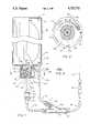
- FIG. 1is a partially cross-sectioned view of a pressurized intravenous fluid injection system embodying the present invention
- FIG. 2is a cross-sectional view taken along the line 2--2 of FIG. 1;
- FIG. 3is a cross-sectional view taken along the line 3--3 of FIG. 1.
- a complete system for feeding intravenous fluids under pressure to a patientis identified by the reference character 10 and includes a generally cylindrical housing 12 formed of a liquid impervious material such as plastic and which is connected to the atmosphere by means of a uni-directional check valve 14 which is mounted over an air inlet opening 16 at the top of the housing to permit air to enter the housing while preventing the flow of fluid out of the housing through the valve 14.
- a uni-directional check valve 14which is mounted over an air inlet opening 16 at the top of the housing to permit air to enter the housing while preventing the flow of fluid out of the housing through the valve 14.
- Mounted within the housing 12is an elastomeric reservoir 18 which contains the intravenous fluid to be administered to the patient.
- the reservoir 18may be of the type described in U.S. Pat. No.
- 4,387,833thus includes an outer rubber sleeve and an inner flexible plastic bag which is formed of a material which is inert with respect to the intravenous fluid carried thereby.
- the fluidis initially fed under pressure into the reservoir 18 causing the rubber shell to expand and thereafter to exert pressure on the fluid contents.
- a spring loaded outlet valve(not entirely shown) is provided at the lower end of the reservoir 18 and includes a nozzle 20 which is biased in an outward direction by the valve spring. When the nozzle 20 is pressed toward the reservoir, the valve is opened to permit the intravenous fluid to flow out through the nozzle 20. As the nozzle is pressed farther towards the reservoir the aperture through the valve increases and therefore the rate of flow through the nozzle 20 also increases. Valves of this type are commonly used with fluid dispensers such, for example, as aerosol cans and the like and any suitable type may be used.
- a metering adjustment mechanism 22which includes a cup-like cap 24 having a cylindrical flange 24a and a bottom end 24b.
- An axial boss 24csealably fits over the nozzle 20 and is provided with a central bore 24d which is aligned with the bore through the nozzle 20.
- a counterbore 24eis provided along the axis of the cap 24 and sealably receives the end of a flexible plastic feed tube 26.
- an airtight drip chamber 27Connected to the other end of the feed tube 26 is an airtight drip chamber 27 which provides a visible indication of the rate at which the intravenous fluid is being infused to the patient.
- the cap 24further includes an internal cylindrical flange 24f which is rotatably received in a generally tubular base member 28. More particularly, the base member 28 is affixed to the bottom of the housing 12 over a centrally disposed outlet therein and includes a depending hollow cylindrical portion 28a into which the flange 24e partially and rotatably extends.
- the member 28further includes three helical ramps 28b which are respectively provided with a plurality of spaced apart notches 28c on the upper edge thereof for respective cooperation with three lugs 24g provided on the inside surface of the flange 24a at locations spaced 120 degrees apart.
- the notchesare V-shaped and the lower surface of the lugs 24g, as shown in FIG.
- the ramps 28bare provided at the bottom edges thereof with upstanding stop shoulders 28d which are in engagement with the lugs 24g when the knob is positioned in its fully retracted position wherein the valve portion of the nozzle 20 is closed.
- the operatorpresses the cap 24 towards the housing and rotates it to that position wherein the lugs 24 are received in the notches which are located at that position.
- the capis released it will then remain in that set position. Inasmuch as the pressure within the reservoir 18 remains substantially constant until substantially all of the fluid has been exhausted from the reservoir the flow rate remains constant at the set value.
- the cap 24is provided with a V-shaped reference notch 24h which together with a plurality of graduation marks 30 on the bottom of the housing 12 provides a visual indication of the rate of flow of intravenous fluid from the reservoir 18.
- a flexible plastic feed tube 31is fitted at one end into the outlet port at the bottom of the drip chamber 27 and its other end is fitted into a Y-shaped fitting 34 having a main straight-through tubular section and a branch section 34a.
- Another flexible tube 36is connected at one of its ends to the other end of the fitting 34, and the tube 36 is connected at its other end to a cannula 38 which includes a needle 39 which is adapted to be inserted through the skin of the patient into, for example, either a vein or an artery.
- a suitable clamp(not shown) may be located on the tube 36 for interrupting the flow of fluid to the patient.
- the branch leg or section of the fitting 34 identified by the reference character 34amay be seen to contain a check valve 41 for transmitting fluid in one direction only, away from the patient, to a flexible tube 43 which is connected at its upper end to a return inlet port 45 in the bottom of the housing 12.
- the leg 34a of the connector 34includes a removable tubular end piece 47 which facilitates assembly of the check valve 41 within the leg 34a.
- the purpose of the return line which includes the check valve 41is to return the I.V. fluid to the portion of the housing which is exterior of the reservoir 18 in the event that the needle 39 is misplaced in the patient and the I.V. fluid is not being fed either to a vein or an artery. When that occurs the fluid backs up in the cannula 38 and in tube 36 and thus flows to the housing through the return line.
- the housing 12is preferably formed of a translucent material but it may be opaque and include a translucent portion in the side wall near the bottom through which the fluid returned to the housing can be seen, thereby providing a visible indication to the operator that the needle 39 has been misplaced in the patient.
- the check valve 41provides an occlusion safety valve and is set to open at a differential pressure which is less than the back pressure which would occur in the tube 36 if the end of the needle 39 were blocked. This pressure is dependent upon whether the infusion is venous or arterial and to some extent on the blood pressure of the patient.
- the cap 24 and the external portion of the base member 28are covered with a plastic shrink safety seal 50 which must be removed before the cap 24 can be depressed to release the intravenous fluid from the reservoir 18.
- the safety sealalso prevents tampering with the contents of the system.
- meansare provided in the return line from the fitting 34 for increasing the visibility of the fluid returned to the housing 12.
- a small quantity of a dye 52is inserted in the end fitting 47 in proximity to and downstream of the check valve 41 so that as the fluid passes through the check valve 41 its color is changed and made more visible as the dye 52 dissolves into the fluid.
- a narrow transverse passagewaycan be provided through the wall of the cap end fitting 47 so that as fluid passes therethrough air is educted through the passageway and appears as bubbles in the fluid as it passes through the tube 43.
- all of the tubes 26, 36 and 43are at least partially transparent so that the colored fluid passing through the tube 43 can be observed by the operator.
- the entire housing 12be translucent or transparent so that any of the intravenous fluid which is returned to the housing can be seen.
- the transparent or translucent housingpermits observation of the reservoir 18 which decreases in size as the contents are depleted. In this way the operator can observe the reservoir 18 and thus estimate the amount of intravenous fluid remaining in the system.
- the drip chamberwhich is formed of a transparent rigid material such as glass or plastic, is provided in the wall thereof with an air injection port covered by a self sealing rubber or rubber-like disc member 27a.
- the intravenous fluidenters the drip chamber through a capillary tube 27b known as a drip former and the fluid drips as discrete drops through the air pocket at the top of the chamber. The attendant can observe the flow rate through the wall of the drip chamber.
- the self-sealing member 27apermits the injection of air into the drip chamber by means of a hypodermic needle inserted into the chamber through the member 27a. When the needle is withdrawn, the opening through the member is automatically resealed.
- Materials from which the disc member may be formedare well known in the art, being used, for example, in the walls of I.V. bags for use in injecting medicaments and the like into the otherwise sealed bag.
- the system shown in FIG. 1is supplied from the manufacturer as a unit with the reservoir 18 filled with a particular intravenous fluid and some means, such as a label on the housing, is provided to indicate the type of intravenous fluid contained therein.
- the entire systemis maintained in a sterilized condition with the cannula 38 being enclosed in the normal manner during shipment and storage.
- the housing 12can be placed in an upright position either above or below the patient, the shrink wrap 50 is then torn off and the cover 24 is pressed in and turned a small amount to fill the line 36 with the fluid.
- the operatorcan then see if any of the fluid is being returned to the housing. If there is no return flow then the operator knows that the needle has been properly inserted into the patient and that the intravenous fluid will flow into the patient at the preset rate. If, on the other hand, the fluid is being returned to the housing, the operator knows that the needle should be repositioned.
- the drip chamber 27can be taped to the side of the housing 12 which can then be placed in an upright position above or below the patient so that the flow rate can be observed in the chamber 27 as drops form and fall from the bottom of the drip tube 27b.
Landscapes
- Health & Medical Sciences (AREA)
- Vascular Medicine (AREA)
- Engineering & Computer Science (AREA)
- Anesthesiology (AREA)
- Biomedical Technology (AREA)
- Heart & Thoracic Surgery (AREA)
- Hematology (AREA)
- Life Sciences & Earth Sciences (AREA)
- Animal Behavior & Ethology (AREA)
- General Health & Medical Sciences (AREA)
- Public Health (AREA)
- Veterinary Medicine (AREA)
- Infusion, Injection, And Reservoir Apparatuses (AREA)
Abstract
Description
The present invention relates in general to systems for supplying intravenous fluids to a patient, and it relates in particular to a new and improved system which incorporates an elastomeric reservoir in which the intravenous fluid is maintained under a substantially constant pressure during the supply of the fluid to the patient.
I.V. systems have generally been of two basic types, one, a gravity feed system in which a collapsible fluid reservoir located in an elevated position is connected to the patient through a manually adjustable valve, and two, a system in which the fluid is physically pumped at an adjustable rate of flow and pressure to the patient. In the first system the feed pressure is limited, while the second system is relatively complex and expensive to manufacture and to maintain. While the use of a pump enables the feeding of fluids under high pressure to the arteries of a patient the pump must be powered by electricity which has restricted its use.
Briefly, there is provided in accordance with the present invention a new and improved system for supplying intravenous fluids to a patient wherein the fluid is retained under pressure in an elastomeric reservoir and supplied to the patient through a manually adjustable metering valve. In a preferred embodiment of the invention the reservoir is housed in a partially translucent housing which is open to the atmosphere through an air inlet located near the top. A flexible feed tube connects the outlet of the metering valve to a cannula for feeding the fluid to the veins or arteries of the patient and a fluid return line, which includes a check valve, is connected between a fluid inlet in the housing and a location in the flexible feed tube between the cannula and the metering valve. In the event that the cannula is misplaced in the patient, the intravenous fluid flows through the return line to the housing where it is collected and provides a visible indication through the translucent portion thereof that the fluid is not flowing to the patient.
In accordance with another feature of the invention, a transparent drip chamber is provided with a self-sealing wall through which air may be injected into the drip chamber.
Further objects and advantages and a better understanding of the present invention will be had by reference to the following detailed description taken in connection with the accompanying drawing wherein:
FIG. 1 is a partially cross-sectioned view of a pressurized intravenous fluid injection system embodying the present invention;
FIG. 2 is a cross-sectional view taken along theline 2--2 of FIG. 1; and
FIG. 3 is a cross-sectional view taken along the line 3--3 of FIG. 1.
A complete system for feeding intravenous fluids under pressure to a patient is identified by thereference character 10 and includes a generallycylindrical housing 12 formed of a liquid impervious material such as plastic and which is connected to the atmosphere by means of auni-directional check valve 14 which is mounted over an air inlet opening 16 at the top of the housing to permit air to enter the housing while preventing the flow of fluid out of the housing through thevalve 14. Mounted within thehousing 12 is anelastomeric reservoir 18 which contains the intravenous fluid to be administered to the patient. Thereservoir 18 may be of the type described in U.S. Pat. No. 4,387,833 and thus includes an outer rubber sleeve and an inner flexible plastic bag which is formed of a material which is inert with respect to the intravenous fluid carried thereby. The fluid is initially fed under pressure into thereservoir 18 causing the rubber shell to expand and thereafter to exert pressure on the fluid contents. A spring loaded outlet valve (not entirely shown) is provided at the lower end of thereservoir 18 and includes anozzle 20 which is biased in an outward direction by the valve spring. When thenozzle 20 is pressed toward the reservoir, the valve is opened to permit the intravenous fluid to flow out through thenozzle 20. As the nozzle is pressed farther towards the reservoir the aperture through the valve increases and therefore the rate of flow through thenozzle 20 also increases. Valves of this type are commonly used with fluid dispensers such, for example, as aerosol cans and the like and any suitable type may be used.
In order to permit manual adjustment of the rate of fluid flow from thenozzle 20 there is provided ametering adjustment mechanism 22 which includes a cup-like cap 24 having a cylindrical flange 24a and abottom end 24b. Anaxial boss 24c sealably fits over thenozzle 20 and is provided with acentral bore 24d which is aligned with the bore through thenozzle 20. Acounterbore 24e is provided along the axis of thecap 24 and sealably receives the end of a flexibleplastic feed tube 26. Connected to the other end of thefeed tube 26 is anairtight drip chamber 27 which provides a visible indication of the rate at which the intravenous fluid is being infused to the patient.
Thecap 24 further includes an internalcylindrical flange 24f which is rotatably received in a generallytubular base member 28. More particularly, thebase member 28 is affixed to the bottom of thehousing 12 over a centrally disposed outlet therein and includes a depending hollow cylindrical portion 28a into which theflange 24e partially and rotatably extends. Themember 28 further includes threehelical ramps 28b which are respectively provided with a plurality of spaced apartnotches 28c on the upper edge thereof for respective cooperation with three lugs 24g provided on the inside surface of the flange 24a at locations spaced 120 degrees apart. Preferably the notches are V-shaped and the lower surface of the lugs 24g, as shown in FIG. 1, are also V-shaped to complement the shape of the notches. Theramps 28b are provided at the bottom edges thereof with upstanding stop shoulders 28d which are in engagement with the lugs 24g when the knob is positioned in its fully retracted position wherein the valve portion of thenozzle 20 is closed.
In order to controlably adjust the rate of flow of intravenous fluid through thetube 26 from thereservoir 18, the operator presses thecap 24 towards the housing and rotates it to that position wherein thelugs 24 are received in the notches which are located at that position. When the cap is released it will then remain in that set position. Inasmuch as the pressure within thereservoir 18 remains substantially constant until substantially all of the fluid has been exhausted from the reservoir the flow rate remains constant at the set value.
As best shown in FIG. 2 thecap 24 is provided with a V-shaped reference notch 24h which together with a plurality ofgraduation marks 30 on the bottom of thehousing 12 provides a visual indication of the rate of flow of intravenous fluid from thereservoir 18.
It will be understood that any other suitable metering valve may be used to control the flow rate from the reservoir. A flexibleplastic feed tube 31 is fitted at one end into the outlet port at the bottom of thedrip chamber 27 and its other end is fitted into a Y-shaped fitting 34 having a main straight-through tubular section and a branch section 34a. Anotherflexible tube 36 is connected at one of its ends to the other end of thefitting 34, and thetube 36 is connected at its other end to acannula 38 which includes aneedle 39 which is adapted to be inserted through the skin of the patient into, for example, either a vein or an artery. A suitable clamp (not shown) may be located on thetube 36 for interrupting the flow of fluid to the patient. The branch leg or section of thefitting 34 identified by the reference character 34a may be seen to contain acheck valve 41 for transmitting fluid in one direction only, away from the patient, to aflexible tube 43 which is connected at its upper end to areturn inlet port 45 in the bottom of thehousing 12. The leg 34a of theconnector 34 includes a removabletubular end piece 47 which facilitates assembly of thecheck valve 41 within the leg 34a. The purpose of the return line which includes thecheck valve 41 is to return the I.V. fluid to the portion of the housing which is exterior of thereservoir 18 in the event that theneedle 39 is misplaced in the patient and the I.V. fluid is not being fed either to a vein or an artery. When that occurs the fluid backs up in thecannula 38 and intube 36 and thus flows to the housing through the return line.
Thehousing 12 is preferably formed of a translucent material but it may be opaque and include a translucent portion in the side wall near the bottom through which the fluid returned to the housing can be seen, thereby providing a visible indication to the operator that theneedle 39 has been misplaced in the patient.
Thecheck valve 41 provides an occlusion safety valve and is set to open at a differential pressure which is less than the back pressure which would occur in thetube 36 if the end of theneedle 39 were blocked. This pressure is dependent upon whether the infusion is venous or arterial and to some extent on the blood pressure of the patient.
In order to prevent accidental opening of the valve during handling and shipping of the system, thecap 24 and the external portion of thebase member 28 are covered with a plasticshrink safety seal 50 which must be removed before thecap 24 can be depressed to release the intravenous fluid from thereservoir 18. The safety seal also prevents tampering with the contents of the system.
In accordance with another feature of the present invention, means are provided in the return line from thefitting 34 for increasing the visibility of the fluid returned to thehousing 12. In one embodiment of the invention as illustrated in FIG. 1, a small quantity of adye 52 is inserted in the end fitting 47 in proximity to and downstream of thecheck valve 41 so that as the fluid passes through thecheck valve 41 its color is changed and made more visible as thedye 52 dissolves into the fluid. If desired, a narrow transverse passageway can be provided through the wall of the cap end fitting 47 so that as fluid passes therethrough air is educted through the passageway and appears as bubbles in the fluid as it passes through thetube 43. Ordinarily and preferably, all of thetubes tube 43 can be observed by the operator.
As indicated hereinabove, it is preferred that theentire housing 12 be translucent or transparent so that any of the intravenous fluid which is returned to the housing can be seen. In addition, the transparent or translucent housing permits observation of thereservoir 18 which decreases in size as the contents are depleted. In this way the operator can observe thereservoir 18 and thus estimate the amount of intravenous fluid remaining in the system.
In accordance with still another important aspect of the present invention the drip chamber, which is formed of a transparent rigid material such as glass or plastic, is provided in the wall thereof with an air injection port covered by a self sealing rubber or rubber-like disc member 27a. In normal use, the intravenous fluid enters the drip chamber through a capillary tube 27b known as a drip former and the fluid drips as discrete drops through the air pocket at the top of the chamber. The attendant can observe the flow rate through the wall of the drip chamber.
If the air escapes from the drip chamber, there is no way for the attendant to observe the flow rate of intravenous fluid into the patient, and since thereservoir 18 contains no air, in the absence of the injection port it would be very difficult and time consuming to re-establish the air bubble. However, the self-sealingmember 27a permits the injection of air into the drip chamber by means of a hypodermic needle inserted into the chamber through themember 27a. When the needle is withdrawn, the opening through the member is automatically resealed. Materials from which the disc member may be formed are well known in the art, being used, for example, in the walls of I.V. bags for use in injecting medicaments and the like into the otherwise sealed bag.
In use, the system shown in FIG. 1 is supplied from the manufacturer as a unit with thereservoir 18 filled with a particular intravenous fluid and some means, such as a label on the housing, is provided to indicate the type of intravenous fluid contained therein. The entire system is maintained in a sterilized condition with thecannula 38 being enclosed in the normal manner during shipment and storage. When ready for use, thehousing 12 can be placed in an upright position either above or below the patient, theshrink wrap 50 is then torn off and thecover 24 is pressed in and turned a small amount to fill theline 36 with the fluid. The operator having inserted the needle into the vein or artery of the patient then connects it to theline 36 and rotates thecover 24 to align thegroove 24h with thegraduation 30 on the bottom of the housing which indicates the desired flow rate. By observing thehousing 12 the operator can then see if any of the fluid is being returned to the housing. If there is no return flow then the operator knows that the needle has been properly inserted into the patient and that the intravenous fluid will flow into the patient at the preset rate. If, on the other hand, the fluid is being returned to the housing, the operator knows that the needle should be repositioned.
It will be seen by those skilled in that art that the use of a self-pressurized intravenous fluid reservoir has many advantages over the heretofore used gravity feed system. Unlike the gravity feed systems where the flow rate is dependent on the height of the I.V. bag above the patient and thus varies appreciably when the patient rolls over, the flow rate in the pressurized system is relatively constant. Because higher pressures can be provided, direct infusions can be made into the arteries or other parts of the patient, such, for example, as into the bladder.
Also, in emergency situations as in accidents, it is unnecessary to find a place to hang the bag. For example, thedrip chamber 27 can be taped to the side of thehousing 12 which can then be placed in an upright position above or below the patient so that the flow rate can be observed in thechamber 27 as drops form and fall from the bottom of the drip tube 27b.
While the present invention has been described in connection with a particular embodiment thereof, it will be understood by those in the art that many changes may be made without departing from the true spirit and scope of the present invention. Therefore, it is intended by the appended claims to cover all such changes and modifications which come within the true spirit and scope of this invention.
Claims (14)
1. Apparatus for supplying an intravenous fluid to a patient, comprising in combination
an elastomeric reservoir containing a quantity of intravenous fluid under pressure,
an outlet port from said reservoir,
cannula means for insertion into a vein or artery of said patient,
a first conduit connected between said cannula and said outlet port for carrying said fluid to said cannula,
metering valve means disposed between said port and said cannula for adjustably controlling the rate of flow of said fluid from said reservoir to said cannula,
a housing,
an air inlet port in said housing,
a fluid return inlet port in said housing,
a second conduit connected between said first conduit and said return inlet port, and
first check valve means in said second conduit for preventing the flow of fluid therethrough toward said cannula.
2. Apparatus according to claim 1 comprising
drip chamber means connected between said outlet port and said cannular for providing a visual indication of the rate of flow of said fluid to the patient.
3. Apparatus according to claim 2 wherein said drip chamber comprises
a rigid transparent casing enclosing a drip chamber,
a drip tube means opening into the top of said chamber,
a self sealing injection port in said casing for receiving a hollow needle through which air may be injected into said chamber, and
a fluid outlet port at the bottom of said casing.
4. Apparatus according to claim 2 comprising
a rigid housing enclosing said reservoir,
flexible tube means connecting said outlet port to said drip chamber means,
said flexible tube means being sufficiently long to permit said drip chamber means to be positioned against the side of said housing.
5. Apparatus according to claim 2 comprising
means exclusive of the intravenous fluid path through said drip chamber for injecting air into said chamber.
6. Apparatus for supplying an intravenous fluid to a patient, comprising in combination
an elastomeric reservoir containing a quantity of intravenous fluid under pressure,
an outlet port from said reservoir,
metering valve means disposed over said port for adjustably controlling the rate of flow of said fluid from said reservoir,
cannula means for insertion into a vein or artery of said patient,
a first conduit connected between said cannula and said metering valve means for carrying said fluid to said cannula,
an impervious housing enclosing said reservoir,
an air inlet port in said housing,
a fluid return inlet port in said housing,
a second conduit connected between said first conduit and said return inlet port, and
first check valve means in said second conduit for preventing the flow of fluid therethrough toward said cannula.
7. Apparatus according to claim 6, comprising
second check valve means connected over said air inlet port for preventing the flow of fluid out of said housing through said air inlet port.
8. Apparatus according to claim 8, wherein
said air inlet port is located at a substantial distance above said fluid return inlet port.
9. Apparatus according to claim 8 wherein
said housing includes a translucent portion through which the level of return fluid in said housing can be observed.
10. Apparatus according to claim 8 comprising
means disposed between said first check valve means and said housing for providing a visible indication of fluid flow in said second conduit.
11. Apparatus according to claim 6 comprising
a tubular member mounted in said first conduit means,
said tubular member having a branch conduit therein, and
said first check valve means being mounted in said branch conduit.
12. Apparatus according to claim 12 wherein said first conduit means comprises
a first flexible tube connected between said metering valve means and said tubular member, and
a second flexible tube connected between said tubular member and said cannula.
13. Apparatus according to claim 12 wherein said second conduit means comprises
a third flexible tube connected between said tubular member and said fluid return inlet port.
Priority Applications (1)
| Application Number | Priority Date | Filing Date | Title |
|---|---|---|---|
| US06/920,468US4722732A (en) | 1986-10-20 | 1986-10-20 | Intravenous fluid supply system |
Applications Claiming Priority (1)
| Application Number | Priority Date | Filing Date | Title |
|---|---|---|---|
| US06/920,468US4722732A (en) | 1986-10-20 | 1986-10-20 | Intravenous fluid supply system |
Publications (1)
| Publication Number | Publication Date |
|---|---|
| US4722732Atrue US4722732A (en) | 1988-02-02 |
Family
ID=25443799
Family Applications (1)
| Application Number | Title | Priority Date | Filing Date |
|---|---|---|---|
| US06/920,468Expired - Fee RelatedUS4722732A (en) | 1986-10-20 | 1986-10-20 | Intravenous fluid supply system |
Country Status (1)
| Country | Link |
|---|---|
| US (1) | US4722732A (en) |
Cited By (28)
| Publication number | Priority date | Publication date | Assignee | Title |
|---|---|---|---|---|
| US5013303A (en)* | 1988-11-03 | 1991-05-07 | Yehuda Tamari | Constant pressure infusion device |
| US5080652A (en)* | 1989-10-31 | 1992-01-14 | Block Medical, Inc. | Infusion apparatus |
| US5105983A (en)* | 1989-10-31 | 1992-04-21 | Block Medical, Inc. | Infusion apparatus |
| US5248300A (en)* | 1991-12-16 | 1993-09-28 | Abbott Laboratories | Ambulatory infusion system with spring-pressurized reservoir |
| US5306257A (en)* | 1992-05-04 | 1994-04-26 | Prime Medical Products, Inc. | Drug infuser |
| US5468224A (en)* | 1993-11-30 | 1995-11-21 | Souryal; Tarek O. | Methods of color coding injectable medications |
| EP0636034A4 (en)* | 1992-04-17 | 1996-04-17 | Science Inc | Liquid delivery apparatus. |
| US5702368A (en)* | 1991-07-16 | 1997-12-30 | Heartport, Inc. | System for cardiac procedures |
| US5728077A (en)* | 1992-10-15 | 1998-03-17 | Health Care Technology Australia Pty. Ltd. | Intravenous delivery system |
| US5765568A (en)* | 1994-05-27 | 1998-06-16 | Heartport, Inc. | Catheter system and method for venting the left ventricle |
| US5769812A (en)* | 1991-07-16 | 1998-06-23 | Heartport, Inc. | System for cardiac procedures |
| US5776104A (en)* | 1993-06-01 | 1998-07-07 | Guignard; Mireille | Device for supplying a liquid to a body cavity of a person or an animal and subjecting it to a determined pressure |
| US5957895A (en)* | 1998-02-20 | 1999-09-28 | Becton Dickinson And Company | Low-profile automatic injection device with self-emptying reservoir |
| US6013060A (en)* | 1997-11-19 | 2000-01-11 | Woodard; Robert W. | Intravenous liquid flow regulator |
| US6090096A (en)* | 1997-04-23 | 2000-07-18 | Heartport, Inc. | Antegrade cardioplegia catheter and method |
| US6159178A (en)* | 1998-01-23 | 2000-12-12 | Heartport, Inc. | Methods and devices for occluding the ascending aorta and maintaining circulation of oxygenated blood in the patient when the patient's heart is arrested |
| US6193689B1 (en) | 1997-11-19 | 2001-02-27 | Robert W. Woodard | Intravenous liquid flow regulator |
| US6641556B1 (en)* | 1999-07-06 | 2003-11-04 | Respiratory Support Products, Inc. | Intravenous fluid heating system |
| US20070173778A1 (en)* | 2004-02-12 | 2007-07-26 | Nipro Corporation | Drug solution injector with weighing scale |
| US20080051742A1 (en)* | 2004-07-16 | 2008-02-28 | Sybil Ingram-Campbell | Underwear-Integrated Urine Specimen Collection System and Method Thereof |
| US20100198154A1 (en)* | 2009-02-03 | 2010-08-05 | Simon Michael G | Pressure compensating device |
| US20100198167A1 (en)* | 2009-02-03 | 2010-08-05 | Simon Michael G | IV Flow rate regulator |
| US7887520B2 (en) | 2002-01-16 | 2011-02-15 | Simon Michael G | Pressure compensating IV flow control regulator |
| US20110125103A1 (en)* | 2009-11-25 | 2011-05-26 | Baxter International Inc. | Drip chamber with flow control |
| US20110139276A1 (en)* | 2004-11-17 | 2011-06-16 | Noble House Group Pty Ltd. | Sterile sampling methods and apparatus |
| CN104001231A (en)* | 2014-05-15 | 2014-08-27 | 上海金塔医用器材有限公司 | Safety pump remaining needle |
| US9247902B2 (en) | 2003-11-19 | 2016-02-02 | Noble House Group Pty Ltd. | Sterile sampling methods and apparatus |
| US20160067083A1 (en)* | 2014-09-08 | 2016-03-10 | Doheny Eye Institute | Cannula insertion sustaining systems and devices |
Citations (8)
| Publication number | Priority date | Publication date | Assignee | Title |
|---|---|---|---|---|
| US1664938A (en)* | 1926-10-06 | 1928-04-03 | Mcdonnell Ellen | Surgical appliance |
| US2129983A (en)* | 1936-04-06 | 1938-09-13 | Bacon Jay Harvey | Surgical appliance |
| US3468308A (en)* | 1966-01-17 | 1969-09-23 | Howard R Bierman | Pressure infusion device for ambulatory patients with pressure control means |
| US3506005A (en)* | 1967-02-23 | 1970-04-14 | Arthur S Gilio | Pressure infusion device for medical use |
| US3690318A (en)* | 1970-04-16 | 1972-09-12 | Bourns Inc | Apparatus for parenteral fluid infusion provided with variable flow control means |
| US4143659A (en)* | 1975-08-28 | 1979-03-13 | Helmut Biedermann | Stilligout or dropper particularly for infusion apparatus |
| US4545783A (en)* | 1983-07-11 | 1985-10-08 | Warner-Lambert Company | Rigid medical solution container |
| US4588396A (en)* | 1982-10-22 | 1986-05-13 | Stroebel Maurice G | Apparatus for gravity feed of liquid under constant hydrostatic pressure |
- 1986
- 1986-10-20USUS06/920,468patent/US4722732A/ennot_activeExpired - Fee Related
Patent Citations (8)
| Publication number | Priority date | Publication date | Assignee | Title |
|---|---|---|---|---|
| US1664938A (en)* | 1926-10-06 | 1928-04-03 | Mcdonnell Ellen | Surgical appliance |
| US2129983A (en)* | 1936-04-06 | 1938-09-13 | Bacon Jay Harvey | Surgical appliance |
| US3468308A (en)* | 1966-01-17 | 1969-09-23 | Howard R Bierman | Pressure infusion device for ambulatory patients with pressure control means |
| US3506005A (en)* | 1967-02-23 | 1970-04-14 | Arthur S Gilio | Pressure infusion device for medical use |
| US3690318A (en)* | 1970-04-16 | 1972-09-12 | Bourns Inc | Apparatus for parenteral fluid infusion provided with variable flow control means |
| US4143659A (en)* | 1975-08-28 | 1979-03-13 | Helmut Biedermann | Stilligout or dropper particularly for infusion apparatus |
| US4588396A (en)* | 1982-10-22 | 1986-05-13 | Stroebel Maurice G | Apparatus for gravity feed of liquid under constant hydrostatic pressure |
| US4545783A (en)* | 1983-07-11 | 1985-10-08 | Warner-Lambert Company | Rigid medical solution container |
Cited By (47)
| Publication number | Priority date | Publication date | Assignee | Title |
|---|---|---|---|---|
| US5013303A (en)* | 1988-11-03 | 1991-05-07 | Yehuda Tamari | Constant pressure infusion device |
| US5080652A (en)* | 1989-10-31 | 1992-01-14 | Block Medical, Inc. | Infusion apparatus |
| US5105983A (en)* | 1989-10-31 | 1992-04-21 | Block Medical, Inc. | Infusion apparatus |
| US5702368A (en)* | 1991-07-16 | 1997-12-30 | Heartport, Inc. | System for cardiac procedures |
| US5885238A (en)* | 1991-07-16 | 1999-03-23 | Heartport, Inc. | System for cardiac procedures |
| US5792094A (en) | 1991-07-16 | 1998-08-11 | Heartport, Inc. | Method of delivering cardioplegic fluid to a patient's heart |
| US5769812A (en)* | 1991-07-16 | 1998-06-23 | Heartport, Inc. | System for cardiac procedures |
| US5248300A (en)* | 1991-12-16 | 1993-09-28 | Abbott Laboratories | Ambulatory infusion system with spring-pressurized reservoir |
| EP0636034A4 (en)* | 1992-04-17 | 1996-04-17 | Science Inc | Liquid delivery apparatus. |
| US5306257A (en)* | 1992-05-04 | 1994-04-26 | Prime Medical Products, Inc. | Drug infuser |
| US5728077A (en)* | 1992-10-15 | 1998-03-17 | Health Care Technology Australia Pty. Ltd. | Intravenous delivery system |
| US5776104A (en)* | 1993-06-01 | 1998-07-07 | Guignard; Mireille | Device for supplying a liquid to a body cavity of a person or an animal and subjecting it to a determined pressure |
| US5468224A (en)* | 1993-11-30 | 1995-11-21 | Souryal; Tarek O. | Methods of color coding injectable medications |
| US6398752B1 (en) | 1994-05-27 | 2002-06-04 | William P. Sweezer, Jr. | Method of occluding a patient's ascending aorta and delivery cardioplegic fluid |
| US6248086B1 (en) | 1994-05-27 | 2001-06-19 | Heartport, Inc. | Method for cannulating a patient's aortic arch and occluding the patient's ascending aortic arch |
| US5800375A (en) | 1994-05-27 | 1998-09-01 | Heartport, Inc. | Catheter system and method for providing cardiopulmonary bypass pump support during heart surgery |
| US5765568A (en)* | 1994-05-27 | 1998-06-16 | Heartport, Inc. | Catheter system and method for venting the left ventricle |
| US6293920B1 (en) | 1994-05-27 | 2001-09-25 | Heartport, Inc. | Catheter system and method for providing cardiopulmonary bypass pump support during heart surgery |
| US6090096A (en)* | 1997-04-23 | 2000-07-18 | Heartport, Inc. | Antegrade cardioplegia catheter and method |
| US6932792B1 (en) | 1997-04-23 | 2005-08-23 | Frederick G. St. Goar | Antegrade cardioplegia catheter and method |
| US6193689B1 (en) | 1997-11-19 | 2001-02-27 | Robert W. Woodard | Intravenous liquid flow regulator |
| US6013060A (en)* | 1997-11-19 | 2000-01-11 | Woodard; Robert W. | Intravenous liquid flow regulator |
| US6159178A (en)* | 1998-01-23 | 2000-12-12 | Heartport, Inc. | Methods and devices for occluding the ascending aorta and maintaining circulation of oxygenated blood in the patient when the patient's heart is arrested |
| US6589206B1 (en) | 1998-01-23 | 2003-07-08 | Heartport, Inc. | Methods and devices for occluding the ascending aorta and maintaining circulation of oxygenated blood in the patient when the patient's heart is arrested |
| US6902556B2 (en) | 1998-01-23 | 2005-06-07 | Heartport, Inc. | Methods and devices for occluding the ascending aorta and maintaining circulation oxygenated blood in the patient when the patient's heart is arrested |
| US5957895A (en)* | 1998-02-20 | 1999-09-28 | Becton Dickinson And Company | Low-profile automatic injection device with self-emptying reservoir |
| US6641556B1 (en)* | 1999-07-06 | 2003-11-04 | Respiratory Support Products, Inc. | Intravenous fluid heating system |
| US7887520B2 (en) | 2002-01-16 | 2011-02-15 | Simon Michael G | Pressure compensating IV flow control regulator |
| US8777921B2 (en) | 2003-11-19 | 2014-07-15 | Noble House Group Pty Ltd. | Sterile sampling methods and apparatus |
| US9247902B2 (en) | 2003-11-19 | 2016-02-02 | Noble House Group Pty Ltd. | Sterile sampling methods and apparatus |
| US20160345885A1 (en)* | 2003-11-19 | 2016-12-01 | Noble House Group Pty Ltd. | Sterile sampling methods and apparatus |
| US7753893B2 (en)* | 2004-02-12 | 2010-07-13 | Nipro Corporation | Drug solution injector with weighing scale |
| US20070173778A1 (en)* | 2004-02-12 | 2007-07-26 | Nipro Corporation | Drug solution injector with weighing scale |
| US20080051742A1 (en)* | 2004-07-16 | 2008-02-28 | Sybil Ingram-Campbell | Underwear-Integrated Urine Specimen Collection System and Method Thereof |
| US11638577B2 (en)* | 2004-07-16 | 2023-05-02 | Sybil Ingram-Campbell | Underwear-integrated urine specimen collection system and method thereof |
| US20110139276A1 (en)* | 2004-11-17 | 2011-06-16 | Noble House Group Pty Ltd. | Sterile sampling methods and apparatus |
| US20100198154A1 (en)* | 2009-02-03 | 2010-08-05 | Simon Michael G | Pressure compensating device |
| US20100198167A1 (en)* | 2009-02-03 | 2010-08-05 | Simon Michael G | IV Flow rate regulator |
| US8480634B2 (en) | 2009-02-03 | 2013-07-09 | Michael G. Simon | Pressure compensating device |
| US8556869B2 (en) | 2009-02-03 | 2013-10-15 | Michael G. Simon | IV flow rate regulator |
| US20110125103A1 (en)* | 2009-11-25 | 2011-05-26 | Baxter International Inc. | Drip chamber with flow control |
| US8439880B2 (en) | 2009-11-25 | 2013-05-14 | Baxter Healthcare S.A. | Drip chamber with flow control |
| WO2015172423A1 (en)* | 2014-05-15 | 2015-11-19 | 上海金塔医用器材有限公司 | Safe pump indwelling needle |
| CN104001231B (en)* | 2014-05-15 | 2015-05-27 | 上海金塔医用器材有限公司 | Safety pump remaining needle |
| CN104001231A (en)* | 2014-05-15 | 2014-08-27 | 上海金塔医用器材有限公司 | Safety pump remaining needle |
| US20160067083A1 (en)* | 2014-09-08 | 2016-03-10 | Doheny Eye Institute | Cannula insertion sustaining systems and devices |
| CN107072874A (en)* | 2014-09-08 | 2017-08-18 | 多希尼眼科研究所 | Cannula insertion maintenance system and device |
Similar Documents
| Publication | Publication Date | Title |
|---|---|---|
| US4722732A (en) | Intravenous fluid supply system | |
| US4034754A (en) | Intravenous solution set having a constricted inner diameter portion | |
| US3844283A (en) | Apparatus for aseptically dispensing a measured volume of liquid | |
| US4013072A (en) | Drip chamber for intravenous administration | |
| US4623343A (en) | Parenteral fluid administration apparatus and method | |
| US3886937A (en) | Medical administration set for dispensing plural medical liquids | |
| US5897530A (en) | Enclosed ambulatory pump | |
| US5807312A (en) | Bolus pump apparatus | |
| US4114617A (en) | Apparatus for infusion of a measured volume of blood | |
| US4198971A (en) | Drip chamber with air vent | |
| KR960012362B1 (en) | Liquid injector | |
| US5840071A (en) | Fluid delivery apparatus with flow indicator and vial fill | |
| US4684365A (en) | Disposable refill unit for implanted medication infusion device | |
| US4405316A (en) | Injection site with check valve inlet | |
| US4685910A (en) | Apparatus and method for delivering secondary fluids to a patient using an intravenous administration set feeding a primary fluid | |
| US2693801A (en) | Safety cutoff valve for liquid administering apparatus | |
| US4233973A (en) | Apparatus for administering intravenous drugs | |
| US5192272A (en) | Pack for administration of sterile liquids including pharmaceutical, nutrient and energy-source liquids | |
| US2784733A (en) | Check valve for parenteral solutions | |
| US2989052A (en) | Parenteral fluid equipment | |
| EP0185808B1 (en) | Automatic parenteral infusion apparatus | |
| US2969063A (en) | Parenteral fluid administration equipment | |
| US4576594A (en) | Vented drip chamber for use with a syringe | |
| US3625211A (en) | Failsafe apparatus for administering a parenteral solution | |
| US5868715A (en) | Intravenous metering device having automatic stopper |
Legal Events
| Date | Code | Title | Description |
|---|---|---|---|
| AS | Assignment | Owner name:JAMES HENRY MARTIN, LTD., BURR RIDGE, ILLINOIS, A Free format text:ASSIGNMENT OF ASSIGNORS INTEREST.;ASSIGNOR:MARTIN, JAMES, HENRY;REEL/FRAME:004838/0088 Effective date:19880317 Owner name:JAMES HENRY MARTIN, LTD., A CORP. OF DE.,ILLINOIS Free format text:ASSIGNMENT OF ASSIGNORS INTEREST;ASSIGNOR:MARTIN, JAMES, HENRY;REEL/FRAME:004838/0088 Effective date:19880317 | |
| AS | Assignment | Owner name:MARTIN, JAMES H., ILLINOIS Free format text:ASSIGNMENT OF ASSIGNORS INTEREST.;ASSIGNOR:JAMES HENRY MARTIN, LTD.;REEL/FRAME:005238/0872 Effective date:19900216 | |
| FPAY | Fee payment | Year of fee payment:4 | |
| REMI | Maintenance fee reminder mailed | ||
| LAPS | Lapse for failure to pay maintenance fees | ||
| FP | Lapsed due to failure to pay maintenance fee | Effective date:19960207 | |
| STCH | Information on status: patent discontinuation | Free format text:PATENT EXPIRED DUE TO NONPAYMENT OF MAINTENANCE FEES UNDER 37 CFR 1.362 |