US4722573A - Seat belt-equipped seat assembly - Google Patents
Seat belt-equipped seat assemblyDownload PDFInfo
- Publication number
- US4722573A US4722573AUS06/910,685US91068586AUS4722573AUS 4722573 AUS4722573 AUS 4722573AUS 91068586 AUS91068586 AUS 91068586AUS 4722573 AUS4722573 AUS 4722573A
- Authority
- US
- United States
- Prior art keywords
- seat
- engaging portion
- vehicle floor
- channel
- elongate member
- Prior art date
- Legal status (The legal status is an assumption and is not a legal conclusion. Google has not performed a legal analysis and makes no representation as to the accuracy of the status listed.)
- Expired - Lifetime
Links
- 230000035939shockEffects0.000description4
- 230000000994depressogenic effectEffects0.000description1
- 230000002093peripheral effectEffects0.000description1
Images

Classifications
- B—PERFORMING OPERATIONS; TRANSPORTING
- B60—VEHICLES IN GENERAL
- B60N—SEATS SPECIALLY ADAPTED FOR VEHICLES; VEHICLE PASSENGER ACCOMMODATION NOT OTHERWISE PROVIDED FOR
- B60N2/00—Seats specially adapted for vehicles; Arrangement or mounting of seats in vehicles
- B60N2/02—Seats specially adapted for vehicles; Arrangement or mounting of seats in vehicles the seat or part thereof being movable, e.g. adjustable
- B60N2/04—Seats specially adapted for vehicles; Arrangement or mounting of seats in vehicles the seat or part thereof being movable, e.g. adjustable the whole seat being movable
- B60N2/06—Seats specially adapted for vehicles; Arrangement or mounting of seats in vehicles the seat or part thereof being movable, e.g. adjustable the whole seat being movable slidable
- B60N2/07—Slide construction
- B60N2/0722—Constructive details
- B60N2/073—Reinforcement members preventing slide dislocation
- B—PERFORMING OPERATIONS; TRANSPORTING
- B60—VEHICLES IN GENERAL
- B60N—SEATS SPECIALLY ADAPTED FOR VEHICLES; VEHICLE PASSENGER ACCOMMODATION NOT OTHERWISE PROVIDED FOR
- B60N2/00—Seats specially adapted for vehicles; Arrangement or mounting of seats in vehicles
- B60N2/02—Seats specially adapted for vehicles; Arrangement or mounting of seats in vehicles the seat or part thereof being movable, e.g. adjustable
- B60N2/04—Seats specially adapted for vehicles; Arrangement or mounting of seats in vehicles the seat or part thereof being movable, e.g. adjustable the whole seat being movable
- B60N2/14—Seats specially adapted for vehicles; Arrangement or mounting of seats in vehicles the seat or part thereof being movable, e.g. adjustable the whole seat being movable rotatable, e.g. to permit easy access
- B—PERFORMING OPERATIONS; TRANSPORTING
- B60—VEHICLES IN GENERAL
- B60R—VEHICLES, VEHICLE FITTINGS, OR VEHICLE PARTS, NOT OTHERWISE PROVIDED FOR
- B60R22/00—Safety belts or body harnesses in vehicles
- B60R22/18—Anchoring devices
- B60R22/26—Anchoring devices secured to the seat
Definitions
- the present inventionrelates in general to a seat assembly for a motor vehicle, and more particularly to a seat assembly equipped with a seat belt.
- FIG. 5 of the accompanying drawingswhich is generally designated by numeral 1.
- the seat assembly 1comprises a seat cushion part 2 and a seat back part 3.
- a known reclining mechanismis arranged between the parts 2 and 3 to allow a tilting movement of the seat back part 3 relative to the seat cushion part 2.
- Parallel upper rails 5a and 5bare secured to lower side frames 4a and 4b of the seat cushion part 2.
- the upper rails 5a and 5bare slidably disposed on parallel lower rails 6a and 6b which, in turn, are secured to rectangular rotatable frame 7.
- a known position lock deviceis arranged between the upper and lower rails to lock the upper rails at a desired position relative to the lower rails.
- the rotatable frame 7is rotatably disposed on a support member 8 which is stationarily mounted on a vehicle floor 9.
- the rectangular rotatable frame 7is formed at its depressed center portion with a circular opening 71.
- the peripheral edge 72 of the circular opening 71is slidably disposed in a circular groove 82 formed on an upper raised portion of the support member 8.
- Designated by numeral 81a circular opening formed in the raised center portion of the support member 8, about which is defined the circular groove 82.
- the seat assembly 1is equipped with a seat belt assembly, more particularly, a lap belt assembly which comprises a buckle member 10a fixed to a first belt portion 10c and a tongue member 10b fixed to a second belt portion 10d.
- the first and second belt portions 10c and 10dare connected to the lower side frames 4a and 4b of the seat cushion part 2 through respective retainers 11a and 11b.
- connection of the seat belt assembly to the seat assemblyhas been given little thought.
- such connectionhas been made by using only the retainers 11a and 11b fixed to the lower side frames 4a and 4b of the seat cushion part 2.
- a big loadis entirely applied on the retainers 11a and 11b. This induces sometimes deformation and/or breakage of the frames 4a and 4b of the seat cushion part 2 because the durability of these frames to such shock is usually poor.
- a seat belt-equipped seat assemblymounted on a vehicle floor
- the seat assemblycomprising a seat proper including a seat cushion part and a seat back part, a structure mounted on the vehicle floor, a seat sliding mechanism including a pair of upper rails secured to the seat cushion and a pair of lower rails secured to the structure, the upper rails being slidably disposed on the lower rails so that the seat proper is slidable relative to the vehicle floor, a seat belt having ends which are respectively connected to side frames of the seat cushion part through respective retainers, two brackets respectively connected at their upper ends to the retainers, each bracket having a lower end formed into a first engaging portion, and a second engaging portion defined by either one of the structure and the vehicle floor, the first and second engaging portions interlocking with each other in such a manner that the first engaging portion is slidable with respect to the second engaging portion.
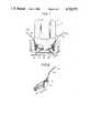
- FIG. 1is a sectional view of a seat belt-equipped seat assembly of a first embodiment of the present invention, which view is taken from a front of the seat assembly;
- FIG. 2is a perspective view of an arrangement employed in the seat assembly of the first embodiment of FIG. 1;
- FIG. 3is a perspective view of a rotatable frame employed in the seat assembly of FIG. 1 for horizontally turning the seat proper relative to a vehicle floor;
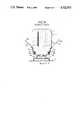
- FIG. 4is a view similar to FIG. 1, but showing a second embodiment of the present invention.
- FIG. 5is a view similar to FIG. 1, but showing a conventional seat belt-equipped seat assembly.
- FIGS. 1 to 3there is shown a seat assembly of a first embodiment of the present invention.
- the seat assembly 1 of this embodimentis provided by modifying the conventional seat assembly of FIG. 5.
- substantially the same parts as those of the conventional seat assemblyare designated by the same numerals and detailed explanation of them will be omitted from the following description.
- the seat assembly 1comprises a seat cushion part 2 and a seat back part 3 between which a known reclining mechanism is arranged.
- Parallel upper rails 5a and 5bare secured to lower side frames 4a and 4b of the seat cushion part 2, which are slidably disposed on parallel lower rails 6a and 6b secured to a rectangular rotatable frame 7.
- the rotatable frame 7is rotatably disposed on a support member 8 through the afore-mentioned turning connection.
- the support member 8is stationarily mounted on a vehicle floor 9.
- the seat properis horizontally rotatable and horizontally linearly movable relative to the vehicle floor 9.
- the seat belt assemblyis mounted to the seat assembly 1 in such a manner as will be described in the following.
- the rectangular rotatable frame 7is formed at the laterally opposed sides with downwardly extending flanges 13a and 13b which act as guide rails as will be apparent as the description proceeds.
- the connection of the seat belt retainers 11a and 11b to the lower side frames 4a and 4b of the seat cushion part 4is made through enlarged brackets 12a and 12b each being bolted to the corresponding lower side frame 4a or 4b.
- the belt retainer 11a or 11bis pivotally connected to the bracket 12a or 12b through one of the bolts.
- Each bracket 12a or 12bhas a channel-shaped lower portion 12c or 12d into which the flange 13a or 13b of the rotatable frame 7 is slidably received.
- the brackets 12a and 12bmove along the flanges 13a and 13b with the channel-shaped lower portions 12c and 12d kept interlocked with the flanges.
- the loadis transmitted or dispersed to not only the lower side frames 4a and 4b of the seat cushion part 2 but also the seat turning mechanism, unlike the case of the afore-mentioned conventional seat assembly.
- the loadis transmitted or dispersed to not only the lower side frames 4a and 4b of the seat cushion part 2 but also the seat turning mechanism, unlike the case of the afore-mentioned conventional seat assembly.
- deformation and/or breakage of the side frames 4a and 4bdoes not occur.
- FIG. 4there is shown a seat assembly of a second embodiment of the present invention.
- the seat assembly 1 of the second embodimentcomprises a seat cushion part 2 and a seat back part 3 between which a known reclining mechanism is arranged.
- Parallel upper rails 5a and 5bare connected through cross beams (no numerals) to lower side frames 4a and 4b of the seat cushion part 2.
- the upper rails 5a and 5bare slidably disposed on parallel lower rails 6a and 6b which are secured to the vehicle floor 9 through mounts 15. With this, the seat proper is horizontally linearly movable relative to the vehicle floor 9.
- connection of the seat belt retainers 11a and 11b to the lower side frames 4a and 4b of the seat cushion part 4is made through elongate brackets 12a and 12b each being secured to the corresponding lower side frame 4a or 4b.
- the belt retainer 11a or 11bis pivotally connected to the bracket 12a or 12b.
- the brackets 12a and 12bhave channel-shaped lower portions 12c and 12d which are slidably received in respective grooves 14a and 14b formed in the vehicle floor 9.
- the grooves 14a and 14bhave longitudinally extending flanges 14c and 14d which are put in the channels of the corresponding brackets 12a and 12b.
- the loadis transmitted or dispersed to not only the lower side frames 4a and 4b of the seat cushion part 2 but also the vehicle floor 9.
- the undesired deformation and/or breakage of the side frames 4a and 4bdoes not occur.
Landscapes
- Engineering & Computer Science (AREA)
- Mechanical Engineering (AREA)
- Aviation & Aerospace Engineering (AREA)
- Transportation (AREA)
- Automotive Seat Belt Assembly (AREA)
- Seats For Vehicles (AREA)
Abstract
Description
Claims (12)
Applications Claiming Priority (2)
| Application Number | Priority Date | Filing Date | Title |
|---|---|---|---|
| JP1985149790UJPS6258248U (en) | 1985-09-30 | 1985-09-30 | |
| JP60-149790[U] | 1985-09-30 |
Publications (1)
| Publication Number | Publication Date |
|---|---|
| US4722573Atrue US4722573A (en) | 1988-02-02 |
Family
ID=15482770
Family Applications (1)
| Application Number | Title | Priority Date | Filing Date |
|---|---|---|---|
| US06/910,685Expired - LifetimeUS4722573A (en) | 1985-09-30 | 1986-09-23 | Seat belt-equipped seat assembly |
Country Status (2)
| Country | Link |
|---|---|
| US (1) | US4722573A (en) |
| JP (1) | JPS6258248U (en) |
Cited By (21)
| Publication number | Priority date | Publication date | Assignee | Title |
|---|---|---|---|---|
| US4986603A (en)* | 1988-06-17 | 1991-01-22 | Tachi-S Co., Ltd. | Frame of a vehicle seat provided with a child seat |
| US5083735A (en)* | 1989-06-30 | 1992-01-28 | Fujikiko Kabushiki Kaisha | Vehicle seat |
| US5209447A (en)* | 1991-11-15 | 1993-05-11 | Tachi-S Co., Ltd. | Cover structure for slide rail in seat adjuster |
| US5228659A (en)* | 1992-08-10 | 1993-07-20 | Hoover Universal, Inc. | Vehicle seat assembly with extending seat track trim cover |
| US5348264A (en)* | 1993-05-28 | 1994-09-20 | Norco Industries, Inc. | Quick release seat pedestal |
| FR2705068A1 (en)* | 1993-05-10 | 1994-11-18 | Cesa | Improved seat and its application in particular to motor vehicles. |
| US5722731A (en)* | 1995-10-25 | 1998-03-03 | Chang; Chung L. | Vehicle seat and seat belt arrangement |
| US5984350A (en)* | 1997-09-22 | 1999-11-16 | Am-Safe, Inc. | Vehicle safety system |
| US20060061196A1 (en)* | 2002-04-30 | 2006-03-23 | Peter Rausch | Longitudinal guide rail for a motor vehicle seat |
| US20090236828A1 (en)* | 2008-03-19 | 2009-09-24 | Daniel Nick Foubert | Inflatable personal restraint systems having web-mounted inflators and associated methods of use and manufacture |
| US7665761B1 (en) | 2008-03-27 | 2010-02-23 | Amsafe, Inc. | Inflatable personal restraint systems and associated methods of use and manufacture |
| JP2010159041A (en)* | 2008-12-12 | 2010-07-22 | Toyota Auto Body Co Ltd | Rotary seat for vehicle and vehicle |
| US8439398B2 (en) | 2011-07-29 | 2013-05-14 | Amsafe, Inc. | Inflator connectors for inflatable personal restraints and associated systems and methods |
| US8523220B1 (en) | 2012-03-19 | 2013-09-03 | Amsafe, Inc. | Structure mounted airbag assemblies and associated systems and methods |
| US9352839B2 (en) | 2014-10-02 | 2016-05-31 | Amsafe, Inc. | Active positioning airbag assembly and associated systems and methods |
| US9511866B2 (en) | 2012-03-19 | 2016-12-06 | Amsafe, Inc. | Structure mounted airbag assemblies and associated systems and methods |
| EP2213504A3 (en)* | 2009-01-29 | 2017-12-27 | Aisin Seiki Kabushiki Kaisha | Rotating seat apparatus for vehicle |
| US9925950B2 (en) | 2015-04-11 | 2018-03-27 | Amsafe, Inc. | Active airbag vent system |
| US9944245B2 (en) | 2015-03-28 | 2018-04-17 | Amsafe, Inc. | Extending pass-through airbag occupant restraint systems, and associated systems and methods |
| CN109050414A (en)* | 2018-07-10 | 2018-12-21 | 上海延锋金桥汽车饰件系统有限公司 | A kind of vehicle mounted electric sliding rail |
| US10604259B2 (en) | 2016-01-20 | 2020-03-31 | Amsafe, Inc. | Occupant restraint systems having extending restraints, and associated systems and methods |
Citations (3)
| Publication number | Priority date | Publication date | Assignee | Title |
|---|---|---|---|---|
| US4072347A (en)* | 1976-01-16 | 1978-02-07 | Societe Industrielle Bertrand Faure Brieres-Les-Scelles | Seat sliding runner |
| DE3018811A1 (en)* | 1980-05-16 | 1981-11-26 | Daimler-Benz Ag, 7000 Stuttgart | Reinforced slide mounting for car seat - has recessed rail inside pressed groove in floor supports |
| DE3226932A1 (en)* | 1982-07-19 | 1984-01-19 | C. Rob. Hammerstein Gmbh, 5650 Solingen | LENGTH GUIDE FOR A VEHICLE SEAT WITH SEAT-FASTENABLE BELT |
Family Cites Families (1)
| Publication number | Priority date | Publication date | Assignee | Title |
|---|---|---|---|---|
| JPS59216750A (en)* | 1983-05-25 | 1984-12-06 | Daihatsu Motor Co Ltd | Load supporting structure for seat belt |
- 1985
- 1985-09-30JPJP1985149790Upatent/JPS6258248U/jaactivePending
- 1986
- 1986-09-23USUS06/910,685patent/US4722573A/ennot_activeExpired - Lifetime
Patent Citations (3)
| Publication number | Priority date | Publication date | Assignee | Title |
|---|---|---|---|---|
| US4072347A (en)* | 1976-01-16 | 1978-02-07 | Societe Industrielle Bertrand Faure Brieres-Les-Scelles | Seat sliding runner |
| DE3018811A1 (en)* | 1980-05-16 | 1981-11-26 | Daimler-Benz Ag, 7000 Stuttgart | Reinforced slide mounting for car seat - has recessed rail inside pressed groove in floor supports |
| DE3226932A1 (en)* | 1982-07-19 | 1984-01-19 | C. Rob. Hammerstein Gmbh, 5650 Solingen | LENGTH GUIDE FOR A VEHICLE SEAT WITH SEAT-FASTENABLE BELT |
Cited By (28)
| Publication number | Priority date | Publication date | Assignee | Title |
|---|---|---|---|---|
| US4986603A (en)* | 1988-06-17 | 1991-01-22 | Tachi-S Co., Ltd. | Frame of a vehicle seat provided with a child seat |
| US5083735A (en)* | 1989-06-30 | 1992-01-28 | Fujikiko Kabushiki Kaisha | Vehicle seat |
| US5209447A (en)* | 1991-11-15 | 1993-05-11 | Tachi-S Co., Ltd. | Cover structure for slide rail in seat adjuster |
| US5228659A (en)* | 1992-08-10 | 1993-07-20 | Hoover Universal, Inc. | Vehicle seat assembly with extending seat track trim cover |
| EP0627337A1 (en)* | 1993-05-10 | 1994-12-07 | Cesa Compagnie Europeenne De Sieges Pour Automobiles | Seat for motor vehicles |
| FR2705068A1 (en)* | 1993-05-10 | 1994-11-18 | Cesa | Improved seat and its application in particular to motor vehicles. |
| US5540482A (en)* | 1993-05-10 | 1996-07-30 | Cesa-Compagnie Europeene De Siges Pour Automobiles | Seat and its application, especially to motor vehicles |
| US5348264A (en)* | 1993-05-28 | 1994-09-20 | Norco Industries, Inc. | Quick release seat pedestal |
| US5722731A (en)* | 1995-10-25 | 1998-03-03 | Chang; Chung L. | Vehicle seat and seat belt arrangement |
| US5971490A (en)* | 1995-10-25 | 1999-10-26 | I.A.P.M., Ltd. | Vehicle seat and seat belt arrangement |
| US5984350A (en)* | 1997-09-22 | 1999-11-16 | Am-Safe, Inc. | Vehicle safety system |
| US20060061196A1 (en)* | 2002-04-30 | 2006-03-23 | Peter Rausch | Longitudinal guide rail for a motor vehicle seat |
| US7384103B2 (en)* | 2002-04-30 | 2008-06-10 | Brose Fahrzeugteile Gmbh & Co. Kg, Coburg | Longitudinal guide rail for motor vehicle seat |
| US7980590B2 (en) | 2008-03-19 | 2011-07-19 | Amsafe, Inc. | Inflatable personal restraint systems having web-mounted inflators and associated methods of use and manufacture |
| US20090236828A1 (en)* | 2008-03-19 | 2009-09-24 | Daniel Nick Foubert | Inflatable personal restraint systems having web-mounted inflators and associated methods of use and manufacture |
| US7665761B1 (en) | 2008-03-27 | 2010-02-23 | Amsafe, Inc. | Inflatable personal restraint systems and associated methods of use and manufacture |
| JP2010159041A (en)* | 2008-12-12 | 2010-07-22 | Toyota Auto Body Co Ltd | Rotary seat for vehicle and vehicle |
| EP2213504A3 (en)* | 2009-01-29 | 2017-12-27 | Aisin Seiki Kabushiki Kaisha | Rotating seat apparatus for vehicle |
| US8439398B2 (en) | 2011-07-29 | 2013-05-14 | Amsafe, Inc. | Inflator connectors for inflatable personal restraints and associated systems and methods |
| US8523220B1 (en) | 2012-03-19 | 2013-09-03 | Amsafe, Inc. | Structure mounted airbag assemblies and associated systems and methods |
| US9511866B2 (en) | 2012-03-19 | 2016-12-06 | Amsafe, Inc. | Structure mounted airbag assemblies and associated systems and methods |
| US9889937B2 (en) | 2012-03-19 | 2018-02-13 | Amsafe, Inc. | Structure mounted airbag assemblies and associated systems and methods |
| US9352839B2 (en) | 2014-10-02 | 2016-05-31 | Amsafe, Inc. | Active positioning airbag assembly and associated systems and methods |
| US9944245B2 (en) | 2015-03-28 | 2018-04-17 | Amsafe, Inc. | Extending pass-through airbag occupant restraint systems, and associated systems and methods |
| US9925950B2 (en) | 2015-04-11 | 2018-03-27 | Amsafe, Inc. | Active airbag vent system |
| US10604259B2 (en) | 2016-01-20 | 2020-03-31 | Amsafe, Inc. | Occupant restraint systems having extending restraints, and associated systems and methods |
| CN109050414A (en)* | 2018-07-10 | 2018-12-21 | 上海延锋金桥汽车饰件系统有限公司 | A kind of vehicle mounted electric sliding rail |
| US11958440B2 (en) | 2018-07-10 | 2024-04-16 | Shanghai Yanfeng Jinqiao Automotive Trim Systems Co. Ltd. | Vehicle interior component |
Also Published As
| Publication number | Publication date |
|---|---|
| JPS6258248U (en) | 1987-04-10 |
Similar Documents
| Publication | Publication Date | Title |
|---|---|---|
| US4722573A (en) | Seat belt-equipped seat assembly | |
| US5213300A (en) | Extruded automotive seat track | |
| US5605368A (en) | Seat sliding device for vehicle | |
| US5984419A (en) | Automotive seat back | |
| US7857350B2 (en) | Seat apparatus for vehicle | |
| JPH08253062A (en) | Seat slide device for automobile | |
| US4863289A (en) | Side roller system for a vehicle seat frame | |
| US4673217A (en) | Belt anchor incorporating a seat track structure | |
| US5785387A (en) | Vehicle seat assembly with position-fixing means | |
| US4685716A (en) | Seat mounting arrangement | |
| US4725032A (en) | Seat slide adjuster for vehicles | |
| US4775126A (en) | Seat slide device | |
| US5957535A (en) | Seat track assembly with vertical dislocation resistance bracket | |
| US5528778A (en) | Seat-bed assembly | |
| US6886797B2 (en) | Seat track assembly | |
| US4949932A (en) | Seat slide device | |
| US8322677B2 (en) | Slide structure of vehicle seat | |
| US6089665A (en) | Load transfer structural member for a seat assembly | |
| US6349914B1 (en) | Seat slide device for vehicles | |
| US6293622B1 (en) | Seat device | |
| GB2287645A (en) | Dual vehicle seat with belt attachment beam | |
| US6036253A (en) | Light weight seat track assembly | |
| US6547331B2 (en) | Arrangement for securing long slide rail device to vehicle | |
| US5150871A (en) | Vehicle seat | |
| EP0221544B1 (en) | Adjustable-height swivel seat for vehicle |
Legal Events
| Date | Code | Title | Description |
|---|---|---|---|
| AS | Assignment | Owner name:IKEDA BUSSAN CO., LTD., NO. 771, KOZONO, AYASE CIT Free format text:ASSIGNMENT OF ASSIGNORS INTEREST.;ASSIGNOR:KOMOHARA, MINORU;REEL/FRAME:004632/0665 Effective date:19861030 Owner name:IKEDA BUSSAN CO., LTD.,JAPAN Free format text:ASSIGNMENT OF ASSIGNORS INTEREST;ASSIGNOR:KOMOHARA, MINORU;REEL/FRAME:004632/0665 Effective date:19861030 | |
| STCF | Information on status: patent grant | Free format text:PATENTED CASE | |
| FEPP | Fee payment procedure | Free format text:PAYOR NUMBER ASSIGNED (ORIGINAL EVENT CODE: ASPN); ENTITY STATUS OF PATENT OWNER: LARGE ENTITY | |
| FPAY | Fee payment | Year of fee payment:4 | |
| FEPP | Fee payment procedure | Free format text:PAYER NUMBER DE-ASSIGNED (ORIGINAL EVENT CODE: RMPN); ENTITY STATUS OF PATENT OWNER: LARGE ENTITY Free format text:PAYOR NUMBER ASSIGNED (ORIGINAL EVENT CODE: ASPN); ENTITY STATUS OF PATENT OWNER: LARGE ENTITY | |
| FPAY | Fee payment | Year of fee payment:8 | |
| FPAY | Fee payment | Year of fee payment:12 |