US4722012A - Disc drive arrangement for a hard disc cartridge having a carriage for accurately positioning a head relative to the cartridge - Google Patents
Disc drive arrangement for a hard disc cartridge having a carriage for accurately positioning a head relative to the cartridgeDownload PDFInfo
- Publication number
- US4722012A US4722012AUS07/047,038US4703887AUS4722012AUS 4722012 AUS4722012 AUS 4722012AUS 4703887 AUS4703887 AUS 4703887AUS 4722012 AUS4722012 AUS 4722012A
- Authority
- US
- United States
- Prior art keywords
- cartridge
- disc
- cylindrical rollers
- carriage
- head
- Prior art date
- Legal status (The legal status is an assumption and is not a legal conclusion. Google has not performed a legal analysis and makes no representation as to the accuracy of the status listed.)
- Expired - Fee Related
Links
Images


Classifications
- G—PHYSICS
- G11—INFORMATION STORAGE
- G11B—INFORMATION STORAGE BASED ON RELATIVE MOVEMENT BETWEEN RECORD CARRIER AND TRANSDUCER
- G11B33/00—Constructional parts, details or accessories not provided for in the other groups of this subclass
- G11B33/14—Reducing influence of physical parameters, e.g. temperature change, moisture, dust
- G11B33/1406—Reducing the influence of the temperature
- G11B33/1433—Reducing the influence of the temperature by reducing the effects of the thermal expansion
- G—PHYSICS
- G11—INFORMATION STORAGE
- G11B—INFORMATION STORAGE BASED ON RELATIVE MOVEMENT BETWEEN RECORD CARRIER AND TRANSDUCER
- G11B17/00—Guiding record carriers not specifically of filamentary or web form, or of supports therefor
- G11B17/02—Details
- G11B17/04—Feeding or guiding single record carrier to or from transducer unit
- G11B17/0401—Details
- G11B17/0405—Closing mechanism, e.g. door
- G11B17/0407—Closing mechanism, e.g. door controlling the loading of the record carrier
Definitions
- the present inventionrelates to a disc drive arrangement for use with a computer for information storage and retrieval, and in particular to a disc drive arrangement which can accept a cartridge containing a hard disc.
- the placement of the recording heads relative to the discis generally accomplished by a voice coil actuator.
- the voice coil actuator arrangementbecomes inoperative. If there is sensitive information on the disc and the operator wishes to remove the disc, the procedure is generally to insert a screwdriver type object into a hole provided in the disc drive in order to release the voice coil actuator and remove the disc. Many times this does not work, with resultant damage to the recording heads or the loss of information from and damage to the disc, or both.
- a third disadvantage with prior art devicesis that the cartridge and thus the disc contained therein may not be positionable with respect to the heads with the desired repeatability.
- Still another disadvantage of prior art drivesis that there is insufficient consideration given to thermal expansion of the various components of the disc drive which occurs as the disc drive is used. Accordingly, the head may not be accurately located or registered with respect to a track on the disc and thus information provided on that track may not be locatable.
- the present inventionis directed to overcoming one or more of the problems thus set forth above.
- a disc drive arrangementfor accessing information from and recording information onto a hard disc retained in a cartridge, which cartridge is removably insertable into the disc drive, comprises a housing, a door, means for mounting the door to the housing, at least one head, and a carriage means for mounting and transporting the head.
- the disc drive arrangementfurther includes means for movably mounting said head to the carriage, means for movably mounting the carriage to the housing, motor means for positioning the carriage relative to the housing, and linkage means operatively connecting the door to the carriage for urging the carriage and head away from the cartridge when the door is open.
- the linkage meansincludes a linkage arrangement which is operatively connected to the door and a lever means for selectively engaging the carriage.
- the lever meanshas a cammed surface and is pivotally mounted in the housing so that, as the linkage arrangement is urged against the cammed surface as said door is opened, the lever means urges the carriage and head away from the cartridge.
- the disc drive arrangementincludes a spindle and means for receiving and driving the disc, said receiving means including means for urging the disc onto the spindle and then urging the cartridge housing away from the spindle as the door closes.
- the receiving meansfurther includes spring means for contacting the cartridge in a plurality of locations so as to resiliently hold the cartridge in a predefined position relative to the receiving means.
- the disc drive arrangementincludes means for balancing the thermal expansion of the housing, the disc and the carriage so that the head is accurately positionable with respect to the disc.
- the balancing meansincludes a first reference point from which the housing and the disc expand in one direction and a second reference point from which the carriage and the head expand toward the disc.
- the disc drive arrangementfurther includes a carriage means including a track secured to the housing and a base, and roller means for interconnecting the base to the track.
- the roller meansincludes a plurality of cylindrical rollers mounted on at least one of said track and said base and wherein said cylindrical rollers ride on a plurality of rods mounted on at least the other of said track and base. This arrangement prevents the accumulation of and crushing of dirt and other contaminants between the roller and the rod as the contaminants tend to fall to one side or the other.
- the present inventionsolves the problems of the prior art in that it provides a disc drive arrangement wherein even during a power failure the head and the carriage on which the head is mounted is urged away from the disc and cartridge as the doors open so that the head does not interfere with any of the information stored on the disc, so that the head is not damaged as the cartridge is removed, and the cartridge can be safely and easily removed from the disc drive to protect any sensitive information which may be contained on the disc in the cartridge.
- the present inventionprovides for the accurate, repeatable positioning of the cartridge and thus the disc with respect to the head by accounting for the thermal expansion of the various components of the disc drive and also by the accurate and repeatable positioning of the cartridge into a receiving means of the disc drive which causes the cartridge to be precisely and repeatably seated on the spindle. Further, the present invention is designed so that contaminants do not interfere with the operation of the carriage.
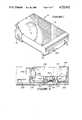
- FIG. 1is a perspective view of an embodiment of the disc drive arrangement of the invention.
- FIG. 2is another perspective view of the disc drive arrangement of FIG. 1 with the door opened and the top thereof removed.
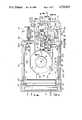
- FIG. 3is a plan view of the embodiment of FIG. 1 with the door opened and the top removed.
- FIG. 4is a cross-sectional view taken through line 4--4 in line FIG. 3.
- FIG. 5is a cross-sectional view taken through line 5--5 in FIG. 3.
- FIG. 6is a cross-sectional view taken through line 6--6 in FIG. 3.
- FIGS. 7A and 7Bare cross-sectional views taken through line 7 in FIG. 3.
- FIG. 8is an exploded view taken through line 8--8 in FIG. 3.
- FIG. 9is a cross-sectional view taken through line 9--9 in FIG. 3.
- Disc drive arrangement 10includes a housing 12 having a cover 14 and a floor 16 (FIG. 2). It should be understood that the electronic and logic circuitry (not shown) is located below floor 16 or at the back of arrangement 10 and is the subject of a co-pending application. Housing 12 includes a door 18 which is pivotally secured thereto along pivotal axis 20.
- the disc drive arrangement 10further includes a linkage means 22 for operatively connecting the door 18 to a carriage 24 which mounts upper and lower recording heads 26 and 28. It is to be understood that although heads 26 and 28 are referred to as recording heads, they can also read information stored on the disc.
- the linkage means 22lifts the heads 26, 28 from the disc 25 and urges the carriage away from the disc drive cartridge 27, shown in phantom in FIGS. 7A, 7B, when the door is opened.
- the disc drive arrangement 10further includes a cam arrangement 20.
- the disc drive arrangement 10also includes cartridge mounting and positioning means 34 and 36 which are actuated when the door 18 is opened and closed.
- the disc drive arrangement 10additionally includes an air filter 38, shown in phantom in FIG. 3, to remove contaminants from the inside of the housing 12.
- the arrangement 10includes a stepper motor 40 which has a shaft 42.
- the shaft 42is operatively connected to the carriage 24 by a band means 44.
- An ejector means 46(FIGS. 2, 3) is mounted with the cartridge mounting and positioning means 36.
- the cartridge mounting and positioning means 34(FIG. 9) includes first and second racks 48 and 50 and pinion 52 which operatively connects first and second racks 48 and 50.
- First and second racks 48 and 50 and pinion 52are provided in mount 54 which is secured to the floor 16 of the housing 12.
- first rack 48includes a pin 56 which is mounted in a slot 57 defined by door 18.
- Pins 60 and 62extend from first rack 48.
- Cartridge mounting and positioning means 34includes a longitudinal channel 64 which can accept an edge of the cartridge 27. Under channel 64 substantially Z-shaped slots 66, 67 are defined into which pins 60 and 62 are disposed.
- Z-shaped slot 66includes a first substantially horizontal portion 68, a second ramped portion 70 which ends in a spiked portion 72 and a second substantially horizontal portion 74.
- Slot 67is similar in configuration. Slots 66, 67 define a motion for the cartridge as the door 18 is closed and the cartridge is placed in the operative position.
- the spiked portion 72as will be described more fully hereinbelow, is to insure that the cartridge is properly seated on the drive spindle 76 which extends through the floor 16.
- cartridge mounting and positioning means 36has a longitudinal channel similar to channel 64 and Z-shaped slots similar to slots 66, 67, the channel being identified by numeral 78. Further a longitudinal member 82 is slidingly pinned through a slot 84 of door 18.
- Arm 150includes an upstanding tab 152 which engages cam arrangement 30 to lift heads 26 and 28 from the upper and lower surfaces of the disc 25 respectively as will be described more fully hereinbelow.
- a second arm 154is pivotally mounted to base 16 at pivot point 156.
- Arm 154is substantially L-shaped and includes a cam surface 158 which is located adjacent pivot point 156 and a bent end 160 which is located distally from pivot point 156.
- the arm 154is biased toward rack 50 by a torsion spring 164.
- Cam surface 158is engaged by the end portion 162 of second rack 50 to urge arm 154 rearwardly as door 18 is opened. This action causes the carriage 24 to be urged rearwardly as will be explained hereinbelow in order to insure that the heads 26 and 28 are out of the way of the cartridge 27 as it is inserted into the disc drive arrangement 10.
- the carriage mounting and positioning means 34includes a spring means which includes leaf springs 200 and 202 (FIGS. 3 and 9) which are mounted in first rack 48 and which cause first rack 48 to be positively positioned with respect to the rest of the housing 54, and also springs 204 and 206 which are located at the ends of channels 64 and 78 and which put a positive downward pressure on the cartridge 27 when it is fully received in said channels. Additionally the spring means includes elastomeric pads 208 and 210 mounted on door 18, which bear down on the upper surface of the cartridge 27 after the door 18 is closed. Finally, the spring means includes a spring 212 (FIG.
- the cam arrangement 30includes a yoke 166 which is pivotally mounted to a base 168 by a pivot pin 170.
- a spring 172is mounted about pin 170 and urges yoke 166 downwardly towards floor 16.
- Base 168is mounted on the back sidewall 174 of housing 12.
- Yoke 166includes first and second arms 176 and 178 which extend toward the door 18 about the carriage 24. Extending inwardly from each arm are first and second roller 180 and 182. These rollers lift the head 26 upwardly as will be described more fully hereinbelow.
- First arm 176includes a cammed lower surface 184 which is engaged by upstanding tab 152 as second rack 50 moves rearwardly. This upstanding tab 152 urges the first leg 176 and thus the yoke 166 upwardly.
- a post 186is upstanding from floor 16 adjacent the end of first arm 176.
- a hydraulic dashpot 188is mounted to post 186. It is to be understood that other types of dashpots or dampers can be used in substitution for hydraulic dashpot 188.
- the upper end of hydraulic dashpot 188is secured to the end of first arm 176.
- Arm 190is also mounted to upstanding post 186.
- Arm 190is pivotable about pin 192.
- Arm 190is disposed above and can engage the lower flexure 120 (described hereinbelow) to which head 28 is secured (FIG. 6).
- Extending rearwardly from arm 190is a second shorter arm 194.
- a spring 196is secured to arm 194 and to the upstanding post 186. Spring 196 causes the arm 190 to be urged downwardly to hold the flexure 120 and head 28 down in a position which is below its normal contacting position with disc 25.
- Arm 194includes a tab 198 which is located beneath the end of the first arm 176 of yoke 166.
- a plurality of roller bearingssuch as roller bearings 214, 216, 218, 220, 222 are mounted on the base 100.
- Roller bearing 224is spring-biased by an elastomeric material 226 or a metallic flexural spring. These roller bearings ride on hardened rods 228 and 230 which are mounted in the track 102.
- roller 224causes all of the rollers to receive evenly the load placed by the base and the rest of the carriage upon the track 102, and also to be understood that as the rollers are cylindrical and as the rods that they ride on substantially describe a line, the path described as the rollers move over the rod is substantially a line. Thus contaminates tend to be urged to one or the other side of the rod rather than being crushed underneath the rollers, so that such contamination does not interfere with the orderly and accurate positioning of the carriage and thus the heads with respect to the disc.
- the carriagefurther includes an anchor plate 234. To anchor plate 234 at position 236 is secured the back end of the band 44.
- Anchor plate 234also includes a downwardly disposed tab 238 (FIGS. 2, 6) which comes into contact with the bent end 160 of arm 154 when the carriage is in the full forward position of FIG. 7B. This downwardly dependent tab 238 is urged rearwardly by the arm 154 so that the carriage is urged rearwardly.
- the anchor plate 234is comprised of, in a preferred embodiment, carbon steel such that the coefficient of expansion of the anchor plate is relatively low compared to the rest of the materials which form the carriage which include aluminum and brass, and the rest of the materials which are used to fabricate the disc drive 10 which are essentially aluminum for the housing 12 and plastic for many of the internal parts.
- the band 44is wrapped about spindle 42.
- the band 44is secured to a U-shaped spring 240 which U-shaped spring is secured to a forward position 242 of base 100.
- the U-shaped spring 240 and the band 44in a preferred embodiment are comprised of a stainless steel material so that their coefficient of expansion is relatively low in comparison to the rest of the disc drive 10. Further, as U-shaped spring 240 is located adjacent disc 25, it heats at about the same rate as does the disc.
- the base 100further includes a first platform 244 to which the second head 28 is secured as will be described below, and a second platform 246 which includes an upstanding post 248 (FIG. 7B) to which the upper head 26 is mounted.
- a first flexible member 106is secured to the top of upstanding post 248.
- the flexible member 106is secured at its opposite end to a platform 108.
- a spring 110is also secured to post 104 above flexible member 106 and is used to urge the platform 108 downwardly.
- Platform 246includes a forwardly positioned upstanding post 250 which is used to provide a stop for the downward movement of the platform 108.
- a first flexure 114is secured to platform 108 at the opposite end to the flexible member 106. At the end of flexure 114 the first or upper head 26 is secured.
- the flexure 114is generally biased downwardly toward the base 100 and a stop 116 is secured to the platform 108 inboard of the flexure 114 to limit the motion of the flexure 114 toward the base.
- Extending from the platform 108 on either side thereofare roller followers 118 and 119 (FIGS. 2, 3) which ride on the inwardly directed rollers 180 and 182 of the yoke 166.
- a second flexure 120Secured to the first platform 244 substantially immediately below the first flexure 144 is a second flexure 120 to which is mounted a second or lower head 28.
- the second flexure 120is biased upwardly.
- another stop 122Mounted to the second platform 246 inboard of the second flexure 120 is another stop 122 which limits the motion of the flexure 120 and the head 28 toward the head 26 which is located immediately thereabove. It is to be understood that when a cartridge with a disc is inserted into the disc drive arrangement 10 that the head 26 can be placed adjacent to the upper surface thereof and the head 28 adjacent to the lower surface thereof so that reading and recording can be accomplished on both sides of the disc.
- the first platformis comprised of brass, and the second and third platforms of aluminum.
- the disc drive arrangement 10 and in particular the carriagehas been carefully constructed so that thermal expansions are balanced. As previously stated, thermal expansion can cause a misalignment of the heads with respect to the tracks on the disc. Such thermal expansion is compensated for by this arrangement 10. From a first reference point including the spindle 76 onto which the cartridge 27 and the hub of the disc is mounted, the housing 12 which is essentially comprised of aluminum expands rearwardly. The hard disc 25 which is also essentially comprised of aluminum expands outwardly, thus both the disc 25 and the housing 12 expand rearwardly from the spindle 76.
- the carriageexpands forward from the reference position 236 where the flexible member 44 is mounted to the anchor plate 234 and compensates for the rearwardly expansion of the housing so that heads remain closely aligned with respect to the tracks on the hard disc. Furthermore the relative thermal expansion of the top head 26 with respect to the bottom head 28 is compensated for by an appropriate choice of materials and securing points 300, 302 and 303.
- the second platformis secured to the first platform at points 300 and 302.
- the third platformis secured to the flexible member 106 made of phosphor bronze at point 303.
- the entire assemblyis secured to the carriage 24 at points 304 and 300. The location of these points has been chosen to have no relative expansion between the bottom head 28 and the top head 26.
- the ejector means 46is mounted in a platform 138 which has upper and lower portions 139 and 141.
- the platform 138serves as a mount for the elongated member 82.
- the ejector means 46includes an ejector pin 140 which is part of an elongated rod 142 which has a bifurcated distal end 144 which is spring-loaded by spring 147 and which has a button 146 affixed to the lower element of the bifurcated end 144.
- the rod 142fits in a bore of platform 138 and button 146 can drop through an aperture 159 which is substantially perpendicular to the bore through which the rod is disposed.
- an elongated member 153which penetrates an aperture (not shown) in the cartridge 27 to actuate the door-opening mechanism thereof.
- This elongated member 153includes a first lower step and a second upper step 155 and 157 respectively. If the cartridge is inserted incorrectly so that the elongated member 154 does not go into the aperture, the cartridge is kept from being inserted fully into the disc drive arrangement 10, and no part of the cartridge comes in contact with and potentially damage the heads 26 and 28.
- the platform 138further mounts the door release and opening mechanism 260.
- This mechanismincludes door-opening button 262 which has an elongated slot 264 set at approximately a 45 degree angle with respect to the platform 138.
- the mechanism 260further includes a rod 266 which has a downwardly dependent pin 268 which is inserted into slot 264.
- the rodis disposed substantially parallel to the door 18 and rests in a bore 270 defined by the platform 138.
- a spring 272is mounted about the rod 266 and is confined between shoulder 274 of the rod and shoulder 276 of the bore.
- the tip of the rod 266can be received in a bore 278 which is defined in the elongated member 82.
- the elongated member 82is further biased toward door 18 by previously identified spring 212 which is mounted in elongated member 82 and is compressed by a downwardly sloping cam surface 280 from the portion 139 of the platform 138.
- spring 212is compressed, and the tip of rod 266 is inserted into aperture 278 fixing the door in the closed position with respect to the rest of the housing 12.
- the button 262is pushed inwardly the slot 264 is translated inwardly so that the pin 268 is urged outwardly with the rest of the rod 266 by the spring 272, releasing the end of rod 266 from the hole 278 and allowing the spring 216 to urge the member 82 forward and pop the door open.
- the member 152causes the ejector mechanism to pop the cartridge out of the housing.
- the operation of the above inventionis as follows. Initially the door 18 of the disc drive arrangement 10 is opened with the simultaneous urging of the carriage 24 rearwardly due to the engagement of the second arm 154 and in particular the bent end 160 with the tab 238 of the carriage, and the upwardly and downward camming of the heads 26 and 28 respectively. When the door is fully down, the carriage 24 is in its fully rearwardly position (FIG. 7A) and the upper and lower heads are in their fully opened position so that the insertion of the cartridge into the appropriate channels of the cartridge mounting and positioning means 34, 36 will not damage the heads. When the cartridge has been slid past elongated member 53 the doors of the cartridge open.
- the cartridgepushes the ejector pin 140 rearwardly locking the button 146 in aperture 150.
- the heads 26, 28enter the cartridge through doors (not shown) in the upper and lower surfaces of the cartridge.
- the dooris closed causing the upstanding tab 152 on the second rack 50 to be moved towards the door, allowing spring 172 to cause the yoke 166 to move towards the floor 16, and with the action of the dashpot 188 allowing the heads 26, 28, in a damped manner, to position themselves adjacent to the upper and lower surfaces of the disc.
- the cartridgeis lowered by the cartridge mounting and positioning means 34 and 36 onto the spindle 76.
- the button 262is pushed causing the door 18 to pop open. From that position the door can be fully extended by the hand of the operator. As this is occurring the member 152 trips the ejector mechanism 46 after the carriage 24 has been moved to its rearward position by second rack 50 so that the ejector pin 140 urges the cartridge out of the disc drive arrangement 10.
- the cartridge and disccan be easily and conveniently removed from the disc drive arrangement without damage to the heads or the information stored on the disc.
- the spring meansallows the cartridge to be positively positioned with respect to the channels so that the disc and the heads are properly aligned.
- the present inventionincludes the advantage that the housing is thermally balanced so that as the various parts expand, this expansion is compensated for and thus the heads stay in the proper track of the disc.
Landscapes
- Moving Of Heads (AREA)
Abstract
Description
Claims (2)
Priority Applications (1)
| Application Number | Priority Date | Filing Date | Title |
|---|---|---|---|
| US07/047,038US4722012A (en) | 1983-08-04 | 1987-05-05 | Disc drive arrangement for a hard disc cartridge having a carriage for accurately positioning a head relative to the cartridge |
Applications Claiming Priority (2)
| Application Number | Priority Date | Filing Date | Title |
|---|---|---|---|
| US06/520,256US4683506A (en) | 1983-08-04 | 1983-08-04 | Disc drive arrangement for a hard disc cartridge with a read/write head retract mechanism |
| US07/047,038US4722012A (en) | 1983-08-04 | 1987-05-05 | Disc drive arrangement for a hard disc cartridge having a carriage for accurately positioning a head relative to the cartridge |
Related Parent Applications (1)
| Application Number | Title | Priority Date | Filing Date |
|---|---|---|---|
| US06/520,256DivisionUS4683506A (en) | 1983-08-04 | 1983-08-04 | Disc drive arrangement for a hard disc cartridge with a read/write head retract mechanism |
Publications (1)
| Publication Number | Publication Date |
|---|---|
| US4722012Atrue US4722012A (en) | 1988-01-26 |
Family
ID=26724561
Family Applications (1)
| Application Number | Title | Priority Date | Filing Date |
|---|---|---|---|
| US07/047,038Expired - Fee RelatedUS4722012A (en) | 1983-08-04 | 1987-05-05 | Disc drive arrangement for a hard disc cartridge having a carriage for accurately positioning a head relative to the cartridge |
Country Status (1)
| Country | Link |
|---|---|
| US (1) | US4722012A (en) |
Cited By (49)
| Publication number | Priority date | Publication date | Assignee | Title |
|---|---|---|---|---|
| US4841394A (en)* | 1986-10-31 | 1989-06-20 | Alps Electric Co., Ltd. | Cover mechanism for a recording medium holding device |
| US4847713A (en)* | 1987-03-25 | 1989-07-11 | Sony Corporation | Disc drive arrangement |
| US4870518A (en)* | 1988-02-26 | 1989-09-26 | Syquest Technology | Removable cartridge disc drive with radial arm voice coil actuator |
| US5079661A (en)* | 1988-07-21 | 1992-01-07 | Alps Electric Co., Ltd. | Magnetic head assembly having consistent track pitch |
| US5253133A (en)* | 1992-01-03 | 1993-10-12 | Cct Inc. | Portable modular hard disk drive |
| US5285336A (en)* | 1990-07-13 | 1994-02-08 | U.S. Philips Corporation | Magnetic-tape-cassette apparatus |
| US5347414A (en)* | 1990-03-27 | 1994-09-13 | Matsushita Electric Industrial Co., Ltd. | Magnetic disk drive with a controllably positioned floating magnetic head |
| US5440436A (en)* | 1992-11-13 | 1995-08-08 | Syquest Technology, Inc. | Removable cartridge disk drive with a 1.8 inch form factor |
| US5444586A (en)* | 1992-11-13 | 1995-08-22 | Syquest Technology, Inc. | Removable cartridge for a disk drive with a 1.8 inch form factor |
| US5508864A (en)* | 1994-10-18 | 1996-04-16 | Iomega Corporation | Flexures which reduce friction in an actuator for a data storage device |
| US5530607A (en)* | 1994-10-18 | 1996-06-25 | Iomega Corporation | Wing attachment for head load/unload in a data storage device |
| US5590095A (en)* | 1991-08-30 | 1996-12-31 | Canon Kabushiki Kaisha | Magneto-optical disk apparatus with floating type magnetic head and a device for limiting an amount of deflection of a resilient member supporting the magnetic head |
| US5625607A (en)* | 1992-02-13 | 1997-04-29 | Canon Kabushiki Kaisha | Magneto-optical disk apparatus including two magnetic field applying devices, one of which has a substantial ring-shaped core member with a gap in a portion thereof |
| USD389810S (en) | 1996-01-29 | 1998-01-27 | Iomega Corporation | Memory device |
| US5768059A (en)* | 1994-10-18 | 1998-06-16 | Iomega Corporation | Head load/unload and cleaning in a data storage device |
| USD397677S (en) | 1996-01-29 | 1998-09-01 | Iomega Corporation | Memory device |
| US5831795A (en)* | 1995-05-10 | 1998-11-03 | Iomega Corporation | Head loading mechanism for a disk drive |
| WO1998054699A1 (en)* | 1997-05-30 | 1998-12-03 | Iomega Corporation | Head gimbal protection for a disk drive |
| US5905607A (en)* | 1997-05-30 | 1999-05-18 | Iomega Corporation | Return path geometry to enhance uniformity of force on a linear actuator |
| US5920445A (en)* | 1997-05-30 | 1999-07-06 | Iomega Corporation | Flexured mounting system for friction reduction and friction linearization in linear actuator for disk drive |
| US5926346A (en)* | 1997-05-30 | 1999-07-20 | Iomega Corporation | Disk drive barriers that restrain movement of the drive actuator |
| US5930090A (en)* | 1997-11-12 | 1999-07-27 | Iomega Corporation | Data cartridge with compression return spring following arcuate guide |
| US5930074A (en)* | 1997-05-30 | 1999-07-27 | Iomega Corporation | Self positioning lever for opening the shutter of a removable disk cartridge |
| USD412318S (en)* | 1997-10-15 | 1999-07-27 | Iomega Corporation | Memory device |
| US5936798A (en)* | 1997-05-30 | 1999-08-10 | Iomega Corporation | Cover for a disk drive assembly |
| US5943194A (en)* | 1996-11-15 | 1999-08-24 | Iomega Corporation | Laminated steel return path with actuator support features |
| US5963399A (en)* | 1997-05-30 | 1999-10-05 | Iomega Corporation | Dual loop flex circuit for a linear actuator |
| US5969908A (en)* | 1997-05-30 | 1999-10-19 | Iomega Corporation | In-rigger of a carriage assembly that prevents rotation of the carriage assembly |
| US5973886A (en)* | 1997-11-14 | 1999-10-26 | Castlewood Systems | Adjustable head load ramp for digital video disk drive system |
| US5982588A (en)* | 1997-05-30 | 1999-11-09 | Iomega Corporation | Elongated rear bearing for linear actuator |
| USD416545S (en) | 1996-01-29 | 1999-11-16 | Iomega Corporation | Computer data storage device |
| US6002547A (en)* | 1997-05-30 | 1999-12-14 | Iomega Corporation | Disk drive with a rotatably mounted disk drive motor |
| US6011673A (en)* | 1993-11-06 | 2000-01-04 | Asahi Kogaku Kogyo Kabushiki Kaisha | Vertical positioning system for a magnetic head base |
| US6064548A (en)* | 1997-05-30 | 2000-05-16 | Iomega Corporation | Eject system for ejecting a disk cartridge from a disk drive |
| US6072666A (en)* | 1997-05-30 | 2000-06-06 | Iomega Corporation | Head retraction system for retracting the heads of a disk drive |
| US6078482A (en)* | 1998-10-16 | 2000-06-20 | Imation Corp. | Data storage cartridge with releasable shutter assembly |
| US6104573A (en)* | 1997-05-30 | 2000-08-15 | Iomega Corporation | Integral lift wing for a disk drive actuator |
| US6111726A (en)* | 1998-04-28 | 2000-08-29 | Imation Corp. | Data storage cartridge with rotary shutter |
| US6137771A (en)* | 1997-04-09 | 2000-10-24 | Iomega Corporation | Shutterless data recording cartridge and drive for using same |
| US6147842A (en)* | 1997-05-30 | 2000-11-14 | Iomega Corporation | Carriage assembly with components molded to a carriage body |
| US6201665B1 (en) | 1997-05-30 | 2001-03-13 | Iomega Corporation | Disk drive load ramp for protecting the actuator heads |
| US6204982B1 (en) | 1997-11-12 | 2001-03-20 | Iomega Corporation | Method and apparatus for cartridge ejection and overwrite protection |
| US6301082B1 (en) | 1997-05-30 | 2001-10-09 | Iomega Corporation | Operating system for operating an eject system and a head retraction system of a disk drive |
| US6310413B1 (en) | 1997-05-30 | 2001-10-30 | Iomega Corporation | Steering magnets to reduce magnetic leakage flux in a disk drive |
| US6353516B2 (en)* | 1998-02-25 | 2002-03-05 | Fujitsu Limited | Disk apparatus having magnetic head lifting device |
| US6430005B1 (en) | 1991-10-18 | 2002-08-06 | Syquest Technology, Inc. | Removable cartridge disk drive with a receiver for receiving a cartridge housing a hard disk |
| US6490242B1 (en) | 1997-04-29 | 2002-12-03 | Brian T. Bonn | Disk cartridge with dual housing structure |
| US6985430B1 (en) | 2003-11-18 | 2006-01-10 | Storage Technology Corporation | Transducer positioning device |
| US7123450B1 (en) | 2003-11-18 | 2006-10-17 | Storage Technology Corporation | Transducer positioning device utilizing a guide member mounted with flexible members |
Citations (17)
| Publication number | Priority date | Publication date | Assignee | Title |
|---|---|---|---|---|
| US3896495A (en)* | 1974-02-25 | 1975-07-22 | Control Data Corp | Mechanically isolated transducer head with spring loaded arm for flying |
| US4017898A (en)* | 1974-10-11 | 1977-04-12 | Redlake Corporation | Method and apparatus for recording and reproducing video signals |
| US4206489A (en)* | 1977-07-07 | 1980-06-03 | Basf Aktiengesellschaft | Device for the automatic loading/unloading of at least one magnetic head in a magnetic disc drive |
| US4302789A (en)* | 1980-02-08 | 1981-11-24 | Magnetic Peripherals Inc. | Disc memory head arm lift mechanism |
| US4308564A (en)* | 1979-11-26 | 1981-12-29 | Xerox Corporation | Head load/unload mechanism for rotating magnetic memories |
| US4310864A (en)* | 1979-06-04 | 1982-01-12 | Magnetic Peripherals Inc. | Cartridge loading and unloading mechanism |
| JPS57205870A (en)* | 1981-06-15 | 1982-12-17 | Matsushita Electric Ind Co Ltd | Magnetic disc device |
| US4368495A (en)* | 1979-07-13 | 1983-01-11 | Tokyo Shibaura Denki Kabushiki Kaisha | Cartridge loading mechanism for magnetic disk drive |
| US4392165A (en)* | 1981-03-30 | 1983-07-05 | Disctron, Inc. | Head lift mechanism |
| US4396963A (en)* | 1981-03-31 | 1983-08-02 | Disctron | Access door latch and interlock mechanism |
| US4418370A (en)* | 1979-12-05 | 1983-11-29 | Xerox Corporation | Band drive actuator |
| US4456937A (en)* | 1981-05-14 | 1984-06-26 | Seagate Technology | Head positioning assembly for disc apparatus |
| US4470088A (en)* | 1982-01-08 | 1984-09-04 | Xerox Corporation | Pivot suspension for head arm on disk drive |
| US4471396A (en)* | 1981-05-14 | 1984-09-11 | Seagate Technology | Disc recording apparatus including integral track zero and crash stop means |
| US4480281A (en)* | 1982-09-30 | 1984-10-30 | Gill Cantwell | System for mounting magnetic transducer means on opposite sides of a flexible rotating magnetic disc |
| US4504879A (en)* | 1982-06-04 | 1985-03-12 | Syquest Technology | Disc drive arrangement |
| US4683506A (en)* | 1983-08-04 | 1987-07-28 | Syquest Technology | Disc drive arrangement for a hard disc cartridge with a read/write head retract mechanism |
- 1987
- 1987-05-05USUS07/047,038patent/US4722012A/ennot_activeExpired - Fee Related
Patent Citations (17)
| Publication number | Priority date | Publication date | Assignee | Title |
|---|---|---|---|---|
| US3896495A (en)* | 1974-02-25 | 1975-07-22 | Control Data Corp | Mechanically isolated transducer head with spring loaded arm for flying |
| US4017898A (en)* | 1974-10-11 | 1977-04-12 | Redlake Corporation | Method and apparatus for recording and reproducing video signals |
| US4206489A (en)* | 1977-07-07 | 1980-06-03 | Basf Aktiengesellschaft | Device for the automatic loading/unloading of at least one magnetic head in a magnetic disc drive |
| US4310864A (en)* | 1979-06-04 | 1982-01-12 | Magnetic Peripherals Inc. | Cartridge loading and unloading mechanism |
| US4368495A (en)* | 1979-07-13 | 1983-01-11 | Tokyo Shibaura Denki Kabushiki Kaisha | Cartridge loading mechanism for magnetic disk drive |
| US4308564A (en)* | 1979-11-26 | 1981-12-29 | Xerox Corporation | Head load/unload mechanism for rotating magnetic memories |
| US4418370A (en)* | 1979-12-05 | 1983-11-29 | Xerox Corporation | Band drive actuator |
| US4302789A (en)* | 1980-02-08 | 1981-11-24 | Magnetic Peripherals Inc. | Disc memory head arm lift mechanism |
| US4392165A (en)* | 1981-03-30 | 1983-07-05 | Disctron, Inc. | Head lift mechanism |
| US4396963A (en)* | 1981-03-31 | 1983-08-02 | Disctron | Access door latch and interlock mechanism |
| US4456937A (en)* | 1981-05-14 | 1984-06-26 | Seagate Technology | Head positioning assembly for disc apparatus |
| US4471396A (en)* | 1981-05-14 | 1984-09-11 | Seagate Technology | Disc recording apparatus including integral track zero and crash stop means |
| JPS57205870A (en)* | 1981-06-15 | 1982-12-17 | Matsushita Electric Ind Co Ltd | Magnetic disc device |
| US4470088A (en)* | 1982-01-08 | 1984-09-04 | Xerox Corporation | Pivot suspension for head arm on disk drive |
| US4504879A (en)* | 1982-06-04 | 1985-03-12 | Syquest Technology | Disc drive arrangement |
| US4480281A (en)* | 1982-09-30 | 1984-10-30 | Gill Cantwell | System for mounting magnetic transducer means on opposite sides of a flexible rotating magnetic disc |
| US4683506A (en)* | 1983-08-04 | 1987-07-28 | Syquest Technology | Disc drive arrangement for a hard disc cartridge with a read/write head retract mechanism |
Non-Patent Citations (2)
| Title |
|---|
| IBM Technical Discl. Bulletin, vol. 20, No. 6, Nov. 1977, pp. 2362 2363, Head Retraction Latch Mechanism by Hall, Jr. et al.* |
| IBM Technical Discl. Bulletin, vol. 20, No. 6, Nov. 1977, pp. 2362-2363, "Head Retraction Latch Mechanism" by Hall, Jr. et al. |
Cited By (62)
| Publication number | Priority date | Publication date | Assignee | Title |
|---|---|---|---|---|
| US4841394A (en)* | 1986-10-31 | 1989-06-20 | Alps Electric Co., Ltd. | Cover mechanism for a recording medium holding device |
| US4847713A (en)* | 1987-03-25 | 1989-07-11 | Sony Corporation | Disc drive arrangement |
| US4870518A (en)* | 1988-02-26 | 1989-09-26 | Syquest Technology | Removable cartridge disc drive with radial arm voice coil actuator |
| US5079661A (en)* | 1988-07-21 | 1992-01-07 | Alps Electric Co., Ltd. | Magnetic head assembly having consistent track pitch |
| US5347414A (en)* | 1990-03-27 | 1994-09-13 | Matsushita Electric Industrial Co., Ltd. | Magnetic disk drive with a controllably positioned floating magnetic head |
| US5285336A (en)* | 1990-07-13 | 1994-02-08 | U.S. Philips Corporation | Magnetic-tape-cassette apparatus |
| US5590095A (en)* | 1991-08-30 | 1996-12-31 | Canon Kabushiki Kaisha | Magneto-optical disk apparatus with floating type magnetic head and a device for limiting an amount of deflection of a resilient member supporting the magnetic head |
| US6430005B1 (en) | 1991-10-18 | 2002-08-06 | Syquest Technology, Inc. | Removable cartridge disk drive with a receiver for receiving a cartridge housing a hard disk |
| US6456456B1 (en) | 1991-10-18 | 2002-09-24 | Syquest Technology, Inc. | Removable cartridge disk drive with a receiver for receiving a cartridge housing a hard disk |
| US5253133A (en)* | 1992-01-03 | 1993-10-12 | Cct Inc. | Portable modular hard disk drive |
| US5625607A (en)* | 1992-02-13 | 1997-04-29 | Canon Kabushiki Kaisha | Magneto-optical disk apparatus including two magnetic field applying devices, one of which has a substantial ring-shaped core member with a gap in a portion thereof |
| US5440436A (en)* | 1992-11-13 | 1995-08-08 | Syquest Technology, Inc. | Removable cartridge disk drive with a 1.8 inch form factor |
| US6333834B1 (en) | 1992-11-13 | 2001-12-25 | Syquest Technology, Inc. | Rattle reduction mechanism in a removable cartridge for a disk drive |
| US5724216A (en)* | 1992-11-13 | 1998-03-03 | Syquest Technology, Inc. | Removable cartridge which may be mounted to a disk drive spindle motor without relative movement between the motor and a housing of the cartridge |
| US5831790A (en)* | 1992-11-13 | 1998-11-03 | Syquest Technology, Inc. | Removable cartridge disk drive with a compact mechanism for engaging the disk cartridge and drive spindle motor |
| US6049444A (en)* | 1992-11-13 | 2000-04-11 | Syquest Technology, Inc. | Rotatable door and door opening mechanism for a cartridge |
| US5444586A (en)* | 1992-11-13 | 1995-08-22 | Syquest Technology, Inc. | Removable cartridge for a disk drive with a 1.8 inch form factor |
| US6011673A (en)* | 1993-11-06 | 2000-01-04 | Asahi Kogaku Kogyo Kabushiki Kaisha | Vertical positioning system for a magnetic head base |
| US5768059A (en)* | 1994-10-18 | 1998-06-16 | Iomega Corporation | Head load/unload and cleaning in a data storage device |
| US5530607A (en)* | 1994-10-18 | 1996-06-25 | Iomega Corporation | Wing attachment for head load/unload in a data storage device |
| US5508864A (en)* | 1994-10-18 | 1996-04-16 | Iomega Corporation | Flexures which reduce friction in an actuator for a data storage device |
| US5831795A (en)* | 1995-05-10 | 1998-11-03 | Iomega Corporation | Head loading mechanism for a disk drive |
| USD397677S (en) | 1996-01-29 | 1998-09-01 | Iomega Corporation | Memory device |
| USD389810S (en) | 1996-01-29 | 1998-01-27 | Iomega Corporation | Memory device |
| USD416545S (en) | 1996-01-29 | 1999-11-16 | Iomega Corporation | Computer data storage device |
| US6141189A (en)* | 1996-11-15 | 2000-10-31 | Iomega Corporation | Laminated steel return path with actuator support features |
| US5943194A (en)* | 1996-11-15 | 1999-08-24 | Iomega Corporation | Laminated steel return path with actuator support features |
| US6137771A (en)* | 1997-04-09 | 2000-10-24 | Iomega Corporation | Shutterless data recording cartridge and drive for using same |
| US6490242B1 (en) | 1997-04-29 | 2002-12-03 | Brian T. Bonn | Disk cartridge with dual housing structure |
| US5982588A (en)* | 1997-05-30 | 1999-11-09 | Iomega Corporation | Elongated rear bearing for linear actuator |
| US6191913B1 (en) | 1997-05-30 | 2001-02-20 | Iomega Corporation | Motor loading system for a disk drive |
| US5969908A (en)* | 1997-05-30 | 1999-10-19 | Iomega Corporation | In-rigger of a carriage assembly that prevents rotation of the carriage assembly |
| US5963399A (en)* | 1997-05-30 | 1999-10-05 | Iomega Corporation | Dual loop flex circuit for a linear actuator |
| US5995326A (en)* | 1997-05-30 | 1999-11-30 | Iomega Corporation | Head gimbal protection for a disk drive |
| US6002547A (en)* | 1997-05-30 | 1999-12-14 | Iomega Corporation | Disk drive with a rotatably mounted disk drive motor |
| US5936798A (en)* | 1997-05-30 | 1999-08-10 | Iomega Corporation | Cover for a disk drive assembly |
| US6555043B2 (en) | 1997-05-30 | 2003-04-29 | Iomega Corporation | Method of making a carriage assembly for a disk drive |
| US6064548A (en)* | 1997-05-30 | 2000-05-16 | Iomega Corporation | Eject system for ejecting a disk cartridge from a disk drive |
| US6072666A (en)* | 1997-05-30 | 2000-06-06 | Iomega Corporation | Head retraction system for retracting the heads of a disk drive |
| WO1998054699A1 (en)* | 1997-05-30 | 1998-12-03 | Iomega Corporation | Head gimbal protection for a disk drive |
| US6104573A (en)* | 1997-05-30 | 2000-08-15 | Iomega Corporation | Integral lift wing for a disk drive actuator |
| US5905607A (en)* | 1997-05-30 | 1999-05-18 | Iomega Corporation | Return path geometry to enhance uniformity of force on a linear actuator |
| US6137651A (en)* | 1997-05-30 | 2000-10-24 | Iomega Corporation | Flexured mounting system for friction reduction and friction linearization in linear actuator for disk drive |
| US5930074A (en)* | 1997-05-30 | 1999-07-27 | Iomega Corporation | Self positioning lever for opening the shutter of a removable disk cartridge |
| US5920445A (en)* | 1997-05-30 | 1999-07-06 | Iomega Corporation | Flexured mounting system for friction reduction and friction linearization in linear actuator for disk drive |
| US6147842A (en)* | 1997-05-30 | 2000-11-14 | Iomega Corporation | Carriage assembly with components molded to a carriage body |
| US6359756B1 (en) | 1997-05-30 | 2002-03-19 | Iomega Corporation | Disk drive having a system for protecting the read/write heads |
| US6198605B1 (en) | 1997-05-30 | 2001-03-06 | Iomega Corporation | Return path geometry to enhance uniformity of force on a linear actuator |
| US6201665B1 (en) | 1997-05-30 | 2001-03-13 | Iomega Corporation | Disk drive load ramp for protecting the actuator heads |
| US5926346A (en)* | 1997-05-30 | 1999-07-20 | Iomega Corporation | Disk drive barriers that restrain movement of the drive actuator |
| US6301082B1 (en) | 1997-05-30 | 2001-10-09 | Iomega Corporation | Operating system for operating an eject system and a head retraction system of a disk drive |
| US6306332B1 (en) | 1997-05-30 | 2001-10-23 | Iomega Corporation | Method of making an in-rigger of a carriage assembly that prevents rotation of the carriage assembly |
| US6310413B1 (en) | 1997-05-30 | 2001-10-30 | Iomega Corporation | Steering magnets to reduce magnetic leakage flux in a disk drive |
| USD412318S (en)* | 1997-10-15 | 1999-07-27 | Iomega Corporation | Memory device |
| US6204982B1 (en) | 1997-11-12 | 2001-03-20 | Iomega Corporation | Method and apparatus for cartridge ejection and overwrite protection |
| US5930090A (en)* | 1997-11-12 | 1999-07-27 | Iomega Corporation | Data cartridge with compression return spring following arcuate guide |
| US5973886A (en)* | 1997-11-14 | 1999-10-26 | Castlewood Systems | Adjustable head load ramp for digital video disk drive system |
| US6353516B2 (en)* | 1998-02-25 | 2002-03-05 | Fujitsu Limited | Disk apparatus having magnetic head lifting device |
| US6111726A (en)* | 1998-04-28 | 2000-08-29 | Imation Corp. | Data storage cartridge with rotary shutter |
| US6078482A (en)* | 1998-10-16 | 2000-06-20 | Imation Corp. | Data storage cartridge with releasable shutter assembly |
| US6985430B1 (en) | 2003-11-18 | 2006-01-10 | Storage Technology Corporation | Transducer positioning device |
| US7123450B1 (en) | 2003-11-18 | 2006-10-17 | Storage Technology Corporation | Transducer positioning device utilizing a guide member mounted with flexible members |
Similar Documents
| Publication | Publication Date | Title |
|---|---|---|
| US4722012A (en) | Disc drive arrangement for a hard disc cartridge having a carriage for accurately positioning a head relative to the cartridge | |
| US4683506A (en) | Disc drive arrangement for a hard disc cartridge with a read/write head retract mechanism | |
| US4504879A (en) | Disc drive arrangement | |
| US4965685A (en) | Removable cartridge disc drive with radial arm voice coil actuator | |
| CA1328505C (en) | Removable cartridge disc drive with radial arm voice coil actuator | |
| CA1109147A (en) | Cartridge loading mechanism | |
| JP3523120B2 (en) | Magneto-optical recording / reproducing device | |
| JPS58224480A (en) | Disc driver | |
| JPS60243856A (en) | Magnetic disk writing/reading device | |
| JPS61292261A (en) | Cartridge handler | |
| JP3890660B2 (en) | Disc recording and / or playback device | |
| US6226252B1 (en) | Picker shipping lock mechanism for data storage system | |
| JP2000339817A (en) | Spring assembly for energizing tape cartridge | |
| US4603362A (en) | Guiding and registering different thickness diskettes in a disk drive | |
| JPS6142332B2 (en) | ||
| JPS6325862A (en) | Tape driving mechanism | |
| JPS6220624B2 (en) | ||
| US4763213A (en) | Double-sided floppy disk driving apparatus having a mechanism for preventing heads from coming into contact with each other | |
| US4654734A (en) | Magnetic disk drive | |
| JPS6120261A (en) | Operation mechanism for flexible disc driving | |
| SU1578760A1 (en) | Flexible magnetic disc memory | |
| JPH0621076Y2 (en) | Disk drive | |
| JP3800755B2 (en) | Disk unit | |
| KR830001224B1 (en) | Video disc support and route setting device for video disc player | |
| JPH0624034Y2 (en) | Floppy disk drive |
Legal Events
| Date | Code | Title | Description |
|---|---|---|---|
| CC | Certificate of correction | ||
| FEPP | Fee payment procedure | Free format text:PAT HLDR NO LONGER CLAIMS SMALL ENT STAT AS INDIV INVENTOR (ORIGINAL EVENT CODE: LSM1); ENTITY STATUS OF PATENT OWNER: LARGE ENTITY | |
| FPAY | Fee payment | Year of fee payment:4 | |
| AS | Assignment | Owner name:SYQUEST TECHNOLOGY, INC., CALIFORNIA Free format text:MERGER;ASSIGNOR:SYQUEST TECHNOLOGY;REEL/FRAME:006607/0001 Effective date:19911106 | |
| FPAY | Fee payment | Year of fee payment:8 | |
| AS | Assignment | Owner name:GREYROCK BUSINESS CREDIT, CALIFORNIA Free format text:SECURITY INTEREST;ASSIGNOR:SYQUEST TECHNOLOGY, INC.;REEL/FRAME:007920/0120 Effective date:19960315 | |
| AS | Assignment | Owner name:IOMEGA CORPORATION, UTAH Free format text:ASSIGNMENT OF ASSIGNORS INTEREST;ASSIGNOR:SYQUESTTECHNOLOGY, INC.;REEL/FRAME:009987/0931 Effective date:19990402 | |
| REMI | Maintenance fee reminder mailed | ||
| AS | Assignment | Owner name:IOMEGA CORPORATION, UTAH Free format text:SECURITY AGREEMENT;ASSIGNOR:GREYROCK CAPITAL, A DIVISION OF NATIONSCREDIT...COMMERCIAL CORPORATION;REEL/FRAME:010539/0504 Effective date:20000106 | |
| LAPS | Lapse for failure to pay maintenance fees | ||
| FP | Lapsed due to failure to pay maintenance fee | Effective date:20000126 | |
| AS | Assignment | Owner name:EMC CORPORATION,MASSACHUSETTS Free format text:ASSIGNMENT OF ASSIGNORS INTEREST;ASSIGNOR:IOMEGA CORPORATION;REEL/FRAME:023953/0328 Effective date:20100211 Owner name:EMC CORPORATION, MASSACHUSETTS Free format text:ASSIGNMENT OF ASSIGNORS INTEREST;ASSIGNOR:IOMEGA CORPORATION;REEL/FRAME:023953/0328 Effective date:20100211 | |
| STCH | Information on status: patent discontinuation | Free format text:PATENT EXPIRED DUE TO NONPAYMENT OF MAINTENANCE FEES UNDER 37 CFR 1.362 |