US4721830A - Cable enclosure - Google Patents
Cable enclosureDownload PDFInfo
- Publication number
- US4721830A US4721830AUS07/066,309US6630987AUS4721830AUS 4721830 AUS4721830 AUS 4721830AUS 6630987 AUS6630987 AUS 6630987AUS 4721830 AUS4721830 AUS 4721830A
- Authority
- US
- United States
- Prior art keywords
- housing
- cable
- header
- housing members
- enclosure
- Prior art date
- Legal status (The legal status is an assumption and is not a legal conclusion. Google has not performed a legal analysis and makes no representation as to the accuracy of the status listed.)
- Expired - Lifetime
Links
- 239000000725suspensionSubstances0.000claimsabstractdescription16
- 239000004020conductorSubstances0.000claimsdescription4
- 239000002184metalSubstances0.000description4
- 238000010276constructionMethods0.000description2
- 238000009434installationMethods0.000description2
- 238000000034methodMethods0.000description2
- 239000004033plasticSubstances0.000description2
- 239000011248coating agentSubstances0.000description1
- 238000000576coating methodMethods0.000description1
- 150000001875compoundsChemical class0.000description1
- 230000000994depressogenic effectEffects0.000description1
- 239000000463materialSubstances0.000description1
- 230000013011matingEffects0.000description1
- 239000002991molded plasticSubstances0.000description1
- 238000010137moulding (plastic)Methods0.000description1
- 238000004382pottingMethods0.000description1
- 230000001681protective effectEffects0.000description1
- 230000029058respiratory gaseous exchangeEffects0.000description1
- 238000013024troubleshootingMethods0.000description1
- 238000011179visual inspectionMethods0.000description1
Images


Classifications
- H—ELECTRICITY
- H02—GENERATION; CONVERSION OR DISTRIBUTION OF ELECTRIC POWER
- H02G—INSTALLATION OF ELECTRIC CABLES OR LINES, OR OF COMBINED OPTICAL AND ELECTRIC CABLES OR LINES
- H02G15/00—Cable fittings
- H02G15/08—Cable junctions
- H02G15/10—Cable junctions protected by boxes, e.g. by distribution, connection or junction boxes
- H02G15/117—Cable junctions protected by boxes, e.g. by distribution, connection or junction boxes for multiconductor cables
Definitions
- This inventionrelates to enclosures for electrical cables, and in particular to a new and improved enclosure suitable for use in enclosing splices in telephone cables, which is sometimes referred to as a free breathing aerial enclosure.
- the telephone cablesare supported overhead on a messenger cable and conductors in the various cables are spliced togeher by a workman while in the overhead position, and the resultant splices are enclosed in a protective enclosure.
- One type of enclosure used in the pastis in the form of a flexible boot or sleeve having an axial slit or opening along one side. After the electrical splicing has been completed, the sleeve is spread apart and positioned over the splice and the cables. Typically the sleeve is tapered at the ends to provide a closer fit with the cables themselves.
- Various types of fastenersare used for closing the sleeve along the slit, and sometimes a potting compound is introduced into the sleeve.
- Typical enclosures of this typeare shown in U.S. Pat. Nos. 4,084,067; 4,084,066; 4,015,072; 3,916,086; and 3,916,082.
- Another type of cable enclosure used in the pastcomprises two pieces generally semicircular in shape, with the two pieces being bolted or otherwise joined together about the splice and cables.
- the two piecesare cast of metal or molded of a rigid plastic. Enclosures of this type are shown in U.S. Pat. Nos. 3,915,540 and 3,798,349.
- Cable splicesare made by workmen in the field under difficult working conditions.
- the workmanis up in the air at the cable height, working from a ladder or from an aerial platform.
- a dropped part or a dropped tooloften means a trip to the ground for a replacement.
- An additional object of the inventoris to provide such a cable enclosure which can be installed and used as a single unit.
- An additional objectis to provide such a cable enclosure which can be attached to a messenger cable, with all of the components assembled with the enclosure so that there are no loose parts for dropping or misplacing.
- a cable enclosure for enclosing electrical cable splicesincluding an elongated housing with first and second housing members, with the housing members joined along an edge for movement between closed and open conditions, and an elongate header having means for attachment to a messenger cable and means for engagement with the housing members as they are joined together at the header.
- the enclosurealso includes a suspension arrangement for suspending the housing members from the header when in the open condition, providing access to the cables while maintaining the housing members ready for closure about the splice when completed.
- an electrical conducting ground baris carried in the header for a direct ground connection to the messenger cable and for direct ground connection to the cable sheaths and for supporting the cables and supporting the housing members.
- the preferred embodimentalso incorporates replaceable end plates for the ends of the housing members, with various end plates providing for various numbers of cables entering the housing, including blank end plates where no cable entry is desired.
- FIG. 1is a side view of a cable enclosure installed on a messenger cable and incorporating the presently preferred embodiment of the invention
- FIG. 2is an enlarged end view of the enclosure of FIG. 1;
- FIGS. 3 and 4are views similar to that of FIG. 2 showing alternative configurations for the end plates of the housing;
- FIG. 5is an enlarged partial sectional view taken along the line 5--5 of FIG. 1;
- FIG. 6is a perspective view illustrating the latching arrangement for the housing members and header of FIG. 5;
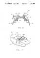
- FIG. 7is a perspective view of the enclosure of FIG. 1, with the housing in the open condition;
- FIG. 8is a view similar to that of FIG. 7, with the housing in the open and suspended condition;
- FIG. 9is an exploded view illustrating the replaceable end plates for a housing member
- FIG. 10is an enlarged partial sectional view taken along the line 10--10 of FIG. 1;
- FIG. 11is a perspective view illustrating the closure of FIG. 10;
- FIG. 12is an enlarged partial side view of the configuration of FIG. 8 illustrating the suspension of the housing members.
- FIG. 13is an end view of the configuration of FIG. 12.
- a cable enclosure 21is shown suspended from a messenger cable 22.
- the cable enclosureincludes a housing formed of two housing members 23, 24 joined at a hinge 25.
- the housing membersare molded plastic shells, and may be identical so that both can be made from a single die.
- the hingecomprises a plurality of molded tubular sections along the lower edge of the housing member, with the tubular sections along the lower edge of the housing of the opposed housing members can be aligned, with a metal rod 26 positioned through the aligned sections to serve as the hinge pin.
- the cable enclosurealso includes a header 29, a ground bar 30, and a latch bar 31, with these three components connected to a messenger attachment bar 32 by a bolt 33.
- the messenger cable 22is clamped against the attachment bar 32 by a clamp 34 and bolt 35.
- the headerpreferably is a plastic molding, and has spaced grooves 38 for receiving the upper edges 39 of the housing members 23, 24.
- each of the housint membershas an internal rib 40 which serves as an internal rain gutter for diverting moisture from the central portion of the interior of the housing.
- the latch bar 31typically is a piece of resilient metal, with ends 42 projecting beyond the header 29 and overlying the upper edges 39 of the housing members 23, 24. Bosses 43 are provided on the housing members adjacent the upper edges for engagement with corresponding slots 44 in the latch bar 31. This configuration is shown in the unlatched condition in FIG. 6 and in the latched condition in FIG. 5.
- the ground bar 30typically is a metal channel which extends the length of the header, andis shown in greater detail in FIGS. 12 and 13. With the mounting configuration as shown in FIG. 5, there is a direct metallic ground between the ground bar 30, the bolt 33, the attachment bar 32, and the messenger cable 22.
- the flanges of the ground bar channelmay be provided with slots and other openings for various purposes, some of which will be described hereinbelow.
- Closure means 47are provided on the enclosure for closing the housing members on the header, and are best shown in FIGS. 10 and 11.
- Two spaced transverse ribs 48are carried on the header 29, and longitudinal ribs 49 are provided at the upper edges of the respective housing members 23, 24.
- Support flanges 50preferably are formed integral with the respective ribs 49 and housing members.
- Bolt 51 with clerance on the bolt shaft between the head and the threaded endis carried in an opening in one of the ribs 49, for engagement with a captive nut 52 carried on the other rib 49.
- the bolts 51are advanced to engage the respective nuts 52 and are tightened.
- Engagement of the housing member ribs 49 with the header ribs 48limits the closing of the housing members on the header to prevent damage to the components by overtightening of the bolts.
- the cable enclosureis shown in the fully open condition in FIG. 8, with the housing member 23 suspended from the header by straps 54 and with the housing member 24 suspended from the housing member 23 by the hinge. Cables 55, 56 are suspended below the header 29, by cable ties 57.
- An alternative arrangment for supporting the cablesis also shown, comprising brackets 58 attached to the underside of the header 29, with each bracket having one or more curved supports 59 and associated strap 60 for strapping a cable against the support.
- One or the other or both types of cables supportcan be used as desired.
- FIG. 8shows two cables entering the enclosure, but various numbers of cables can be utilized as dictated by the service. Arrangements for various numbers of cables will be described hereinbelow.
- a plurality of ground lines 63is also incorporated in the cable enclosure.
- the ground linesmay be conventional in construction, comprising an electrical conductor with an insulating coating, with the conductor connected at one end to the ground bar 30, and having a ground connector 64 at the other end for attachment to the ground sheath of
- the flanges of the ground barare provided with a plurality of slots 66.
- One end 67 of the strap 54is threaded through the slots as shown in FIG. 13, and then attached to the housing member 23, as by positioning over a boss molded in the housing member, or by a rivet, or otherwise as desired.
- the other end of the strapis folded over on itself or otherwise increased in size so that it will not pass through the slots.
- the cable ties 57which may be conventional wire or cable ties, also pass through the slots 66.
- the ground wire 63is attached to the central portion of the ground bar 30 by a screw in the conventional manner.
- the cable enclosure of the inventionis adapted for handling various numbers of cables, depending upon the specific requirement in the field.
- the enclosure shown in FIG. 1is handling four cables, with each cable entering through a tapered boot 68 which may be conventional in design.
- the end view of FIG. 2shows access for two cables.
- the alterative configuration of FIG. 3shows access for three cables, while the alternative configuration of FIG. 4 shows access for a single cable.
- Each of the housing membershas end sections 69, with the two end sections of the two housing members abutting when the housing is in the closed condition, to close the end of the housing.
- the end section constructionis shown in greater detail in FIG. 9.
- a semicircular rim 70 and a semioval plate opening 71are provided in the end section 69.
- the plate opening 71has a channel configuration for slidingly receiving various end plates 73, 74, 75.
- Each of the end plateshas a latch tongue 76 which engages a latch housing 77 on the end section, for latching the end plate in the end section.
- the end plate 73has two of the semicircular rims 70, the end plate 74 has one semicircular rim, and the end plate 75 is blank.
- the end plate 4is used, for the configuration of FIG. 3, the end plate 73 is used, and for the configuration of FIG. 4, the end plate 75 is used.
- the latch tongue 76is resilient so that the end plate can be pushed into the channel and the catch of the tongue deflected to engage the latch housing. Then when it is desired to change end plates, the latch tongue is manually depressed to release the latch, and the end plate is removed.
- the workmandetermines the number and location of the cables which are involved. Then the appropriate end plates for each end of the housing are selected and inserted. The desired number of ground wires 63 are determined and installed.
- the housingis closed by engaging one of the housing members with the latch bars 31, as shown in FIG. 7, and then engaging the other housing member with the latch bars.
- the enclosureis now in the condition of FIG. 1 and is ready for attachment to the messenger cable. At this time, the enclosure is supported by the workman in position at the messenger cable, a clamp 34 is placed in position and the bolt 35 is tightened. This procedure is repeated for the other end of the enclosure, and the enclosure is now supported from the messenger cable.
- the enclosureis opened to the position of FIG. 7 by manually pushing upward on the latch bars to release the housing member 24.
- the housingis then lowered to the position of FIG. 8, by releasing the housing member 23 from the latch bars.
- the cables to be splicedare placed in position and supported by the cable ties 57 and/or the cable brackets 58.
- the position of the housing membersmay be raised or lowered by adjusting the straps 54 in the ground bar 30. The workman now proceeds with the necessary splicing, having access to the cables from all sides.
- the housing membersare raised to the position of FIG. 7 and one housing member is engaged with the latch bars This is a simple operation which requires no tools.
- the other housing memberis engaged with the latch bars to close the housing, leaving the enclosure as shown in FIG. 1.
- the housing closures 47are now engaged, by manually running the bolt 51 into the nut 52, and then tightening the bolt with a wrench or nut driver.
- the tapered boots 68are connected to the respective end sections of the housing members by a tie line or other flexible connection, so as to be a connected component of the cable enclosure.
- Each bootis slid over the cable and then clamped onto the annular rim formed by the mating of two of the semicircular rims 70. This completes the installation of the cable enclosure.
- the cable enclosure when once installed on the messenger cableis a unitary structure without any loose parts and which may be opened and closed manually without requiring any complex manipulation and without requiring any tools except for the tightening and loosening of the messenger cable clamp bolts and the closure bolts.
Landscapes
- Cable Accessories (AREA)
Abstract
Description
This invention relates to enclosures for electrical cables, and in particular to a new and improved enclosure suitable for use in enclosing splices in telephone cables, which is sometimes referred to as a free breathing aerial enclosure.
In a typical installation, the telephone cables are supported overhead on a messenger cable and conductors in the various cables are spliced togeher by a workman while in the overhead position, and the resultant splices are enclosed in a protective enclosure.
One type of enclosure used in the past is in the form of a flexible boot or sleeve having an axial slit or opening along one side. After the electrical splicing has been completed, the sleeve is spread apart and positioned over the splice and the cables. Typically the sleeve is tapered at the ends to provide a closer fit with the cables themselves. Various types of fasteners are used for closing the sleeve along the slit, and sometimes a potting compound is introduced into the sleeve. Typical enclosures of this type are shown in U.S. Pat. Nos. 4,084,067; 4,084,066; 4,015,072; 3,916,086; and 3,916,082.
Another type of cable enclosure used in the past comprises two pieces generally semicircular in shape, with the two pieces being bolted or otherwise joined together about the splice and cables. Typically the two pieces are cast of metal or molded of a rigid plastic. Enclosures of this type are shown in U.S. Pat. Nos. 3,915,540 and 3,798,349.
Another type of enclosure sometimes used is a flexible sheet or sheets of material, typically plastic, which are wrapped around the splice and cables after completion of the splice. An enclosure of this type is shown in U.S. Pat. No. 3,557,298.
Cable splices are made by workmen in the field under difficult working conditions. The workman is up in the air at the cable height, working from a ladder or from an aerial platform. A dropped part or a dropped tool often means a trip to the ground for a replacement.
It is an object of the present invention to provide a new and improved cable enclosure which is very easy to work with in the air, and which is usable for enclosing an initial splicing operation, and equally usable with subsequent splices. An additional object of the inventor is to provide such a cable enclosure which can be installed and used as a single unit. An additional object is to provide such a cable enclosure which can be attached to a messenger cable, with all of the components assembled with the enclosure so that there are no loose parts for dropping or misplacing. It is another object of the invention to provide such a cable enclosure which can be removed from the cable splice area, exposing the splice area from all sides, while maintaining the cable enclosure suspended at the work site and ready for positioning about the splice when work is completed.
These and other objects, advantages, features and results will more fully appear in the course of the following description.
A cable enclosure for enclosing electrical cable splices including an elongated housing with first and second housing members, with the housing members joined along an edge for movement between closed and open conditions, and an elongate header having means for attachment to a messenger cable and means for engagement with the housing members as they are joined together at the header. The enclosure also includes a suspension arrangement for suspending the housing members from the header when in the open condition, providing access to the cables while maintaining the housing members ready for closure about the splice when completed.
In the preferred embodiment of the invention, an electrical conducting ground bar is carried in the header for a direct ground connection to the messenger cable and for direct ground connection to the cable sheaths and for supporting the cables and supporting the housing members.
The preferred embodiment also incorporates replaceable end plates for the ends of the housing members, with various end plates providing for various numbers of cables entering the housing, including blank end plates where no cable entry is desired.
FIG. 1 is a side view of a cable enclosure installed on a messenger cable and incorporating the presently preferred embodiment of the invention;
FIG. 2 is an enlarged end view of the enclosure of FIG. 1;
FIGS. 3 and 4 are views similar to that of FIG. 2 showing alternative configurations for the end plates of the housing;
FIG. 5 is an enlarged partial sectional view taken along theline 5--5 of FIG. 1;
FIG. 6 is a perspective view illustrating the latching arrangement for the housing members and header of FIG. 5;
FIG. 7 is a perspective view of the enclosure of FIG. 1, with the housing in the open condition;
FIG. 8 is a view similar to that of FIG. 7, with the housing in the open and suspended condition;
FIG. 9 is an exploded view illustrating the replaceable end plates for a housing member;
FIG. 10 is an enlarged partial sectional view taken along theline 10--10 of FIG. 1;
FIG. 11 is a perspective view illustrating the closure of FIG. 10;
FIG. 12 is an enlarged partial side view of the configuration of FIG. 8 illustrating the suspension of the housing members; and
FIG. 13 is an end view of the configuration of FIG. 12.
In FIGS. 1 and 2, acable enclosure 21 is shown suspended from amessenger cable 22. The cable enclosure includes a housing formed of twohousing members hinge 25. Typically the housing members are molded plastic shells, and may be identical so that both can be made from a single die. Typically the hinge comprises a plurality of molded tubular sections along the lower edge of the housing member, with the tubular sections along the lower edge of the housing of the opposed housing members can be aligned, with ametal rod 26 positioned through the aligned sections to serve as the hinge pin.
As best seen in FIG. 5, the cable enclosure also includes aheader 29, aground bar 30, and alatch bar 31, with these three components connected to amessenger attachment bar 32 by abolt 33. Themessenger cable 22 is clamped against theattachment bar 32 by aclamp 34 andbolt 35.
The header preferably is a plastic molding, and has spacedgrooves 38 for receiving theupper edges 39 of thehousing members internal rib 40 which serves as an internal rain gutter for diverting moisture from the central portion of the interior of the housing.
Typically there are two of thelatch bars 31 and of theattachment bars 32, as seen in FIG. 1. Thelatch bar 31 typically is a piece of resilient metal, withends 42 projecting beyond theheader 29 and overlying theupper edges 39 of thehousing members Bosses 43 are provided on the housing members adjacent the upper edges for engagement withcorresponding slots 44 in thelatch bar 31. This configuration is shown in the unlatched condition in FIG. 6 and in the latched condition in FIG. 5.
Theground bar 30 typically is a metal channel which extends the length of the header, andis shown in greater detail in FIGS. 12 and 13. With the mounting configuration as shown in FIG. 5, there is a direct metallic ground between theground bar 30, thebolt 33, theattachment bar 32, and themessenger cable 22. The flanges of the ground bar channel may be provided with slots and other openings for various purposes, some of which will be described hereinbelow.
Closure means 47 are provided on the enclosure for closing the housing members on the header, and are best shown in FIGS. 10 and 11. Two spacedtransverse ribs 48 are carried on theheader 29, andlongitudinal ribs 49 are provided at the upper edges of therespective housing members Support flanges 50 preferably are formed integral with therespective ribs 49 and housing members. Bolt 51 with clerance on the bolt shaft between the head and the threaded end is carried in an opening in one of theribs 49, for engagement with acaptive nut 52 carried on theother rib 49. After the housing members are engaged with thelatch bar 31, thebolts 51 are advanced to engage therespective nuts 52 and are tightened. Engagement of the housing member ribs 49 with theheader ribs 48 limits the closing of the housing members on the header to prevent damage to the components by overtightening of the bolts.
The cable enclosure is shown in the fully open condition in FIG. 8, with thehousing member 23 suspended from the header bystraps 54 and with thehousing member 24 suspended from thehousing member 23 by the hinge.Cables header 29, bycable ties 57. An alternative arrangment for supporting the cables is also shown, comprisingbrackets 58 attached to the underside of theheader 29, with each bracket having one or morecurved supports 59 and associatedstrap 60 for strapping a cable against the support. One or the other or both types of cables support can be used as desired. FIG. 8 shows two cables entering the enclosure, but various numbers of cables can be utilized as dictated by the service. Arrangements for various numbers of cables will be described hereinbelow. A plurality ofground lines 63 is also incorporated in the cable enclosure. The ground lines may be conventional in construction, comprising an electrical conductor with an insulating coating, with the conductor connected at one end to theground bar 30, and having aground connector 64 at the other end for attachment to the ground sheath of a cable.
Referring to FIGS. 12 and 13, the flanges of the ground bar are provided with a plurality ofslots 66. Oneend 67 of thestrap 54 is threaded through the slots as shown in FIG. 13, and then attached to thehousing member 23, as by positioning over a boss molded in the housing member, or by a rivet, or otherwise as desired. The other end of the strap is folded over on itself or otherwise increased in size so that it will not pass through the slots. The cable ties 57, which may be conventional wire or cable ties, also pass through theslots 66. Theground wire 63 is attached to the central portion of theground bar 30 by a screw in the conventional manner.
The cable enclosure of the invention is adapted for handling various numbers of cables, depending upon the specific requirement in the field. The enclosure shown in FIG. 1 is handling four cables, with each cable entering through a taperedboot 68 which may be conventional in design. The end view of FIG. 2 shows access for two cables. The alterative configuration of FIG. 3 shows access for three cables, while the alternative configuration of FIG. 4 shows access for a single cable. Each of the housing members hasend sections 69, with the two end sections of the two housing members abutting when the housing is in the closed condition, to close the end of the housing.
The end section construction is shown in greater detail in FIG. 9. Asemicircular rim 70 and a semioval plate opening 71 are provided in theend section 69. The plate opening 71 has a channel configuration for slidingly receivingvarious end plates latch tongue 76 which engages alatch housing 77 on the end section, for latching the end plate in the end section. Theend plate 73 has two of thesemicircular rims 70, theend plate 74 has one semicircular rim, and theend plate 75 is blank. For the configuration of FIG. 2,the end plate 4 is used, for the configuration of FIG. 3, theend plate 73 is used, and for the configuration of FIG. 4, theend plate 75 is used. Thelatch tongue 76 is resilient so that the end plate can be pushed into the channel and the catch of the tongue deflected to engage the latch housing. Then when it is desired to change end plates, the latch tongue is manually depressed to release the latch, and the end plate is removed.
When a new splice is to be made, the workman determines the number and location of the cables which are involved. Then the appropriate end plates for each end of the housing are selected and inserted. The desired number ofground wires 63 are determined and installed. The housing is closed by engaging one of the housing members with the latch bars 31, as shown in FIG. 7, and then engaging the other housing member with the latch bars. The enclosure is now in the condition of FIG. 1 and is ready for attachment to the messenger cable. At this time, the enclosure is supported by the workman in position at the messenger cable, aclamp 34 is placed in position and thebolt 35 is tightened. This procedure is repeated for the other end of the enclosure, and the enclosure is now supported from the messenger cable.
The enclosure is opened to the position of FIG. 7 by manually pushing upward on the latch bars to release thehousing member 24. The housing is then lowered to the position of FIG. 8, by releasing thehousing member 23 from the latch bars. The cables to be spliced are placed in position and supported by thecable ties 57 and/or thecable brackets 58. The position of the housing members may be raised or lowered by adjusting thestraps 54 in theground bar 30. The workman now proceeds with the necessary splicing, having access to the cables from all sides.
Ater the splicing has been completed, the housing members are raised to the position of FIG. 7 and one housing member is engaged with the latch bars This is a simple operation which requires no tools. After visual inspection to ensure that all is in the proper position within the housing, the other housing member is engaged with the latch bars to close the housing, leaving the enclosure as shown in FIG. 1. Thehousing closures 47 are now engaged, by manually running thebolt 51 into thenut 52, and then tightening the bolt with a wrench or nut driver.
Typically the taperedboots 68 are connected to the respective end sections of the housing members by a tie line or other flexible connection, so as to be a connected component of the cable enclosure. Each boot is slid over the cable and then clamped onto the annular rim formed by the mating of two of thesemicircular rims 70. This completes the installation of the cable enclosure.
When it is desired to carry out additional splicing or troubleshooting or the like, the procedure is reversed. Theboots 68 are removed, thebolts 51 of theclosures 47 are withdrawn from engagement with the corresponding nuts, one housing section is released from the latch bars and rotated downward to the open condition, the other housing section is released from the latch bars and the housing is lowered to the fully open condition of FIG. 8.
Thus it is seen that the cable enclosure when once installed on the messenger cable is a unitary structure without any loose parts and which may be opened and closed manually without requiring any complex manipulation and without requiring any tools except for the tightening and loosening of the messenger cable clamp bolts and the closure bolts.
Claims (23)
1. In a cable enclosure for enclosing electrical cable splices, the combination of:
an elongate housing having first and second housing members each having first and second spaced edges, with said housing members joined together along said first edges for movement between a housing closed condition and a housing open condition;
an elongate header having attachment means for attaching said header to a messenger cable;
said housing members further including closure means for joining said housing members together adjacent said second edges with said header therebetween; and
suspension means connected between said header and one of said housing members for supporting said housing members from said header when in said open condition.
2. A cable enclosure as defined in claim 1 wherein said header includes an upper crown with opposed outwardly facing slots for receiving said housing members second edges.
3. A cable enclosure as defined in claim 2 including spaced upwardly projecting first ribs on said header and upwardly projecting second ribs on said housing members adjacent said second edges, with said second ribs abutting said first ribs when said housing members are in said closed condition, and said closure means includes means for urging said second ribs of opposed housing members against the intervening first ribs.
4. A cable enclosure as defined in claim 3 including a latch bar carried on said header and projecting laterally from said header, and said housing members include latch means engageable with said projecting latch bar when a housing member second edge is positioned in a header slot.
5. A cable enclosure as defined in claim 4 including an electrical conducting ground bar carried by said header with said head attachment means providing an electrical path between said ground bar and the messenger cable.
6. A cable enclosure as defined in claim 5 wherein said ground bar is a downwardly opening channel with suspension slots formed in the opposed arms of said channel, and said suspension means includes a strap attached at one end to a housing member and having the other end threaded through suspension slots for adjusting the position of said housing with respect to said header when in said open condition.
7. A cable enclosure as defined in claim 1 including an electrical conducting ground bar carried by said header with said header attachment means providing an electrical path between said ground bar and the messenger cable.
8. A cable enclosure as defined in claim 7 wherein said ground bar includes a flange with suspension openings, and said suspension means includes a housing line attached at one end to a housing member and having the other end threaded through suspension openings for adjusting the position of said housing with respect to said header when in said open condition.
9. A cable enclosure as defined in claim 8 including a ground conductor fixed at one end to said ground bar and having a connector at the other end for connection to an electrical cable ground sheath.
10. A cable enclosure as defined in claim 9 including a cable suspension line positioned in a ground bar suspension opening for connection about a cable for supporting the cable from said ground bar.
11. A cable enclosure as defined in claim 1 including a cable bracket carried on said header and disposed within said housing when in said closed condition, said cable bracket including first and second spaced curved supports for receiving electrical cables, and a cable strap carried at each support for strapping a cable against said support.
12. A cable enclosure as defined in claim 1 wherein said housing members have end sections which cooperate to close an end of said housing when in said closed condition, with cooperating end sections including replaceable end plates with a pair of end plates having openings defining a cable passage.
13. A cable enclosure as defined in claim 12 with a pair of end plates having openings defining two spaced cable passages.
14. A cable enclosure as defined in claim 13 with a pair of end plates having no openings.
15. A cable enclosure as defined in any of claims 12-14 wherein said housing member end sections include a channel formed therein for slidingly receiving an end plate.
16. A cable enclosure as defined in claim 15 wherein said end sections and said end plates include interengaging latch means for latching an end plate in the channel of an end section.
17. In a cable enclosure for enclosing electrical cable splices, an elongate housing having first and second housing members each having first and second spaced edges, with said housing members joined together along said first edges for movement between a housing closed condition and a housing open condition,
said housing members having end sections which cooperate to close an end of said housing when in said closed condition, said cooperating end sections including replaceable end plates with a pair of end plates having openings defining a cable passage.
18. A cable enclosure as defined in claim 17 with a pair of end plates having openings defining two spaced cable passages.
19. A cable enclosure as defined in claim 18 with a pair of end plates having no openings.
20. A cable enclosure as defined in any of claim 17-19 wherein said housing member end sections include a channel formed therein for slidingly receiving an end plate.
21. A cable enclosure as defined in claim 20 wherein said end sections and said end plates include interengaging latch means for latching an end plate in the channel of an end section.
22. In a cable enclosure for enclosing electrical cable splices, the combination of:
an elongate housing having first and second housing members each having first and second spaced edges, with said housing members joined together along said first edges for movement between a housing closed condition and a housing open condition;
an elongate header having attachment means for attachment said header to a messenger cable;
said housing members further including closure means for joining said housing members together adjacent said second edges with said header therebetween;
suspension means connected between said header and one of said housing members for supporting said housing members from said header when in said open condition; and
an electrical conducting ground bar carried by said header with said header attachment means providing an electrical path between said ground bar and the messenger cable, said ground bar including a flange with suspension openings, and
said suspension means including a housing line attached at one end to a housing member and having the other end threaded through suspension openings for adjusting the position of said housing with respect to said header when in said open condition;
said housing members having end sections which cooperate to close an end of said housing when in said closed condition, with cooperating end sections including replaceable end plates with a pair of end plates having openings defining a cable passage, with said housing member end sections including a channel formed therein for slidingly receiving an end plate, and with said end sections and said end plates including interengaging latch means for latching an end plate in the channel of an end section.
23. A cable enclosure as defined in claim 22 including spaced upwardly projecting first ribs on said header and upwardly projecting second ribs on said housing members adjacent said second edges, with said second ribs abutting said first ribs when said housing members are in said closed condition, and said closure means includes means for urging said second ribs of opposed housing members against the intervening first ribs, and
a latch bar carried on said header and projecting laterally from said header, and said housing members include latch means engageable with said projecting latch bar when a housing member second edge is positioned in a header slot.
Priority Applications (1)
| Application Number | Priority Date | Filing Date | Title |
|---|---|---|---|
| US07/066,309US4721830A (en) | 1987-06-25 | 1987-06-25 | Cable enclosure |
Applications Claiming Priority (1)
| Application Number | Priority Date | Filing Date | Title |
|---|---|---|---|
| US07/066,309US4721830A (en) | 1987-06-25 | 1987-06-25 | Cable enclosure |
Publications (1)
| Publication Number | Publication Date |
|---|---|
| US4721830Atrue US4721830A (en) | 1988-01-26 |
Family
ID=22068695
Family Applications (1)
| Application Number | Title | Priority Date | Filing Date |
|---|---|---|---|
| US07/066,309Expired - LifetimeUS4721830A (en) | 1987-06-25 | 1987-06-25 | Cable enclosure |
Country Status (1)
| Country | Link |
|---|---|
| US (1) | US4721830A (en) |
Cited By (36)
| Publication number | Priority date | Publication date | Assignee | Title |
|---|---|---|---|---|
| US4810829A (en)* | 1987-12-11 | 1989-03-07 | Minnesota Mining And Manufacturing Co. | Cable closure |
| US4994630A (en)* | 1988-12-16 | 1991-02-19 | Rxs Schrumpftechnik-Garnituren Gmbh | Suspended lightweight cable splice enclosure sleeve |
| US5136121A (en)* | 1991-03-29 | 1992-08-04 | At&T Bell Laboratories | Cable terminals |
| US5214248A (en)* | 1991-10-25 | 1993-05-25 | W. R. Grace & Co.-Conn. | Open stay for plastic enclosure |
| US5322973A (en)* | 1992-03-06 | 1994-06-21 | Communication Technology Corporation | Aerial closure |
| USD354734S (en) | 1993-03-24 | 1995-01-24 | Communications Technology Corporation | Inline cable splice housing |
| WO1995023449A1 (en)* | 1994-02-28 | 1995-08-31 | Raychem Corporation | Rodent-proof aerial splice closure |
| USD371116S (en) | 1994-09-29 | 1996-06-25 | Minnesota Mining And Manufacturing Company | Telecommunication cable aerial closure |
| US5557067A (en)* | 1993-07-22 | 1996-09-17 | Communications Technology Corporation | Pole mounted terminal housing |
| USD373771S (en) | 1993-07-22 | 1996-09-17 | Communications Technology Corporation | Pole mounted housing for telecommunication terminals |
| US5561268A (en)* | 1992-03-06 | 1996-10-01 | Communications Technology Corporation | Ends seals for aerial closure |
| US5563372A (en)* | 1992-03-09 | 1996-10-08 | Communications Technology Corporation | Integral terminal housing having folded resilient sheet grommet with slits therein |
| USD375082S (en) | 1993-03-24 | 1996-10-29 | Communications Technology Corporation | Post or strand mounted terminal housing |
| US5569882A (en)* | 1993-11-10 | 1996-10-29 | Yazaki Corporation | Waterproof protective cover |
| US5684274A (en)* | 1995-12-04 | 1997-11-04 | Kmd Technologies, Inc. | Enclosure for cable splice assembly |
| US5696864A (en)* | 1996-09-18 | 1997-12-09 | Communications Technology Corporation | Aerial enclosure for coupling data signals to a customer site |
| USD390571S (en) | 1997-04-10 | 1998-02-10 | Communications Technology Corporation | Terminal block enclosure |
| US6196865B1 (en)* | 1997-10-22 | 2001-03-06 | Aerospatiale Societe Nationale Industrielle | Removable rear connector for a circular electrical plug |
| US6294737B1 (en)* | 1999-06-23 | 2001-09-25 | P. L. Chestney | Reusable closure for wire splices |
| US20020064363A1 (en)* | 2000-10-17 | 2002-05-30 | Preformed Line Products Company | Cable closure and assembly |
| US20060082157A1 (en)* | 2004-10-14 | 2006-04-20 | Czuhanich Michael A | Conduit gland |
| WO2007149104A1 (en)* | 2006-06-23 | 2007-12-27 | 3M Innovative Properties Company | Cable closure end cap |
| US20100092146A1 (en)* | 2008-10-14 | 2010-04-15 | Conner Mark E | Optical Fiber Management Shelf for Optical Connection Terminals |
| US20120175482A1 (en)* | 2011-01-07 | 2012-07-12 | Barry Wayne Allen | Hanger Assemblies and Cabling Management Systems and Methods Including the Same |
| US8755663B2 (en) | 2010-10-28 | 2014-06-17 | Corning Cable Systems Llc | Impact resistant fiber optic enclosures and related methods |
| US8873926B2 (en) | 2012-04-26 | 2014-10-28 | Corning Cable Systems Llc | Fiber optic enclosures employing clamping assemblies for strain relief of cables, and related assemblies and methods |
| US9069151B2 (en) | 2011-10-26 | 2015-06-30 | Corning Cable Systems Llc | Composite cable breakout assembly |
| US9377132B2 (en) | 2014-07-31 | 2016-06-28 | Commscope Technologies Llc | Enclosure hanger assembly and cable management system |
| ITUA20163350A1 (en)* | 2016-05-11 | 2017-11-11 | Antonio Carpino | SHELL FOR LOW VOLTAGE JOINTS FOR GEL INSULATION WITH REMOVABLE BULKHEADS. |
| US9939602B2 (en) | 2014-12-09 | 2018-04-10 | Commscope Technologies Llc | Mounting system and kit for aerial mounting of a fiber optic enclosure |
| CN108879572A (en)* | 2018-08-15 | 2018-11-23 | 深圳供电局有限公司 | High-voltage cable intermediate joint protective shell with stuffing box |
| US10411447B1 (en) | 2018-04-18 | 2019-09-10 | Steed Hammond Paul, Inc. | System for electronic doorframe |
| US10855064B2 (en) | 2018-04-18 | 2020-12-01 | Tadpole Products, Llc | System for electronic doorframe |
| CN112448187A (en)* | 2019-09-05 | 2021-03-05 | Aptiv技术有限公司 | Y-shaped shield joint connector and assembling method thereof |
| US11384591B2 (en) | 2018-04-18 | 2022-07-12 | Tadpole Products, Llc | System for electronic doorframe |
| US20240356318A1 (en)* | 2023-04-24 | 2024-10-24 | Prysmian S.P.A. | Cable retaining arrangement |
Citations (6)
| Publication number | Priority date | Publication date | Assignee | Title |
|---|---|---|---|---|
| CA823804A (en)* | 1969-09-23 | F. Reinisch Frederick | Cable junction box | |
| US3701835A (en)* | 1971-10-12 | 1972-10-31 | Northern Electric Co | Multiple conductor cable terminal |
| US3836696A (en)* | 1973-11-23 | 1974-09-17 | Bell Telephone Labor Inc | Cable terminal |
| GB1419100A (en)* | 1972-11-10 | 1975-12-24 | Hermetite Products Ltd | Cable boxes |
| US3971894A (en)* | 1976-01-15 | 1976-07-27 | Bell Telephone Laboratories, Incorporated | Cable splice closure |
| US4229616A (en)* | 1978-08-10 | 1980-10-21 | Hotchkiss Kenneth W | Cable connector cover |
- 1987
- 1987-06-25USUS07/066,309patent/US4721830A/ennot_activeExpired - Lifetime
Patent Citations (6)
| Publication number | Priority date | Publication date | Assignee | Title |
|---|---|---|---|---|
| CA823804A (en)* | 1969-09-23 | F. Reinisch Frederick | Cable junction box | |
| US3701835A (en)* | 1971-10-12 | 1972-10-31 | Northern Electric Co | Multiple conductor cable terminal |
| GB1419100A (en)* | 1972-11-10 | 1975-12-24 | Hermetite Products Ltd | Cable boxes |
| US3836696A (en)* | 1973-11-23 | 1974-09-17 | Bell Telephone Labor Inc | Cable terminal |
| US3971894A (en)* | 1976-01-15 | 1976-07-27 | Bell Telephone Laboratories, Incorporated | Cable splice closure |
| US4229616A (en)* | 1978-08-10 | 1980-10-21 | Hotchkiss Kenneth W | Cable connector cover |
Cited By (52)
| Publication number | Priority date | Publication date | Assignee | Title |
|---|---|---|---|---|
| US4810829A (en)* | 1987-12-11 | 1989-03-07 | Minnesota Mining And Manufacturing Co. | Cable closure |
| AU599848B2 (en)* | 1987-12-11 | 1990-07-26 | Minnesota Mining And Manufacturing Company | Cable closure |
| US4994630A (en)* | 1988-12-16 | 1991-02-19 | Rxs Schrumpftechnik-Garnituren Gmbh | Suspended lightweight cable splice enclosure sleeve |
| EP0373477A3 (en)* | 1988-12-16 | 1991-05-02 | RXS Schrumpftechnik-Garnituren GmbH | Light construction longitudinally divided overhead sleeve |
| US5136121A (en)* | 1991-03-29 | 1992-08-04 | At&T Bell Laboratories | Cable terminals |
| US5214248A (en)* | 1991-10-25 | 1993-05-25 | W. R. Grace & Co.-Conn. | Open stay for plastic enclosure |
| US5322973A (en)* | 1992-03-06 | 1994-06-21 | Communication Technology Corporation | Aerial closure |
| US5561268A (en)* | 1992-03-06 | 1996-10-01 | Communications Technology Corporation | Ends seals for aerial closure |
| US5563372A (en)* | 1992-03-09 | 1996-10-08 | Communications Technology Corporation | Integral terminal housing having folded resilient sheet grommet with slits therein |
| USD354734S (en) | 1993-03-24 | 1995-01-24 | Communications Technology Corporation | Inline cable splice housing |
| USD375082S (en) | 1993-03-24 | 1996-10-29 | Communications Technology Corporation | Post or strand mounted terminal housing |
| USD373771S (en) | 1993-07-22 | 1996-09-17 | Communications Technology Corporation | Pole mounted housing for telecommunication terminals |
| US5557067A (en)* | 1993-07-22 | 1996-09-17 | Communications Technology Corporation | Pole mounted terminal housing |
| US5569882A (en)* | 1993-11-10 | 1996-10-29 | Yazaki Corporation | Waterproof protective cover |
| US5525756A (en)* | 1994-02-28 | 1996-06-11 | Raychem Corporation | Rodent-proof aerial splice closure |
| WO1995023449A1 (en)* | 1994-02-28 | 1995-08-31 | Raychem Corporation | Rodent-proof aerial splice closure |
| USD371116S (en) | 1994-09-29 | 1996-06-25 | Minnesota Mining And Manufacturing Company | Telecommunication cable aerial closure |
| US5684274A (en)* | 1995-12-04 | 1997-11-04 | Kmd Technologies, Inc. | Enclosure for cable splice assembly |
| US5696864A (en)* | 1996-09-18 | 1997-12-09 | Communications Technology Corporation | Aerial enclosure for coupling data signals to a customer site |
| USD390571S (en) | 1997-04-10 | 1998-02-10 | Communications Technology Corporation | Terminal block enclosure |
| US6196865B1 (en)* | 1997-10-22 | 2001-03-06 | Aerospatiale Societe Nationale Industrielle | Removable rear connector for a circular electrical plug |
| US6294737B1 (en)* | 1999-06-23 | 2001-09-25 | P. L. Chestney | Reusable closure for wire splices |
| US20020064363A1 (en)* | 2000-10-17 | 2002-05-30 | Preformed Line Products Company | Cable closure and assembly |
| WO2002033796A3 (en)* | 2000-10-17 | 2003-01-30 | Preformed Line Products Co | Cable closure and assembly |
| US6721483B2 (en) | 2000-10-17 | 2004-04-13 | Preformed Line Products Company | Cable closure and assembly |
| US20040245008A1 (en)* | 2000-10-17 | 2004-12-09 | Preformed Line Products Company | Cable closure and assembly |
| US20060082157A1 (en)* | 2004-10-14 | 2006-04-20 | Czuhanich Michael A | Conduit gland |
| US7282650B2 (en) | 2004-10-14 | 2007-10-16 | Lockheed Martin Corp. | Conduit gland |
| WO2007149104A1 (en)* | 2006-06-23 | 2007-12-27 | 3M Innovative Properties Company | Cable closure end cap |
| US20090152004A1 (en)* | 2006-06-23 | 2009-06-18 | Pierre Bonvallat | Cable closure end cap |
| US20100092146A1 (en)* | 2008-10-14 | 2010-04-15 | Conner Mark E | Optical Fiber Management Shelf for Optical Connection Terminals |
| US8755663B2 (en) | 2010-10-28 | 2014-06-17 | Corning Cable Systems Llc | Impact resistant fiber optic enclosures and related methods |
| US20120175482A1 (en)* | 2011-01-07 | 2012-07-12 | Barry Wayne Allen | Hanger Assemblies and Cabling Management Systems and Methods Including the Same |
| US9407080B2 (en)* | 2011-01-07 | 2016-08-02 | Commscope Technologies Llc | Hanger assemblies and cabling management systems and methods including the same |
| US9069151B2 (en) | 2011-10-26 | 2015-06-30 | Corning Cable Systems Llc | Composite cable breakout assembly |
| US8873926B2 (en) | 2012-04-26 | 2014-10-28 | Corning Cable Systems Llc | Fiber optic enclosures employing clamping assemblies for strain relief of cables, and related assemblies and methods |
| US9377132B2 (en) | 2014-07-31 | 2016-06-28 | Commscope Technologies Llc | Enclosure hanger assembly and cable management system |
| US9939602B2 (en) | 2014-12-09 | 2018-04-10 | Commscope Technologies Llc | Mounting system and kit for aerial mounting of a fiber optic enclosure |
| US10768390B2 (en) | 2014-12-09 | 2020-09-08 | Commscope Technologies Llc | Mounting system and kit for aerial mounting of a fiber optic enclosure |
| ITUA20163350A1 (en)* | 2016-05-11 | 2017-11-11 | Antonio Carpino | SHELL FOR LOW VOLTAGE JOINTS FOR GEL INSULATION WITH REMOVABLE BULKHEADS. |
| EP3244503A1 (en)* | 2016-05-11 | 2017-11-15 | Carpino, Antonio | Shell for gel isolation low voltage joints with removable bulkheads |
| US11384591B2 (en) | 2018-04-18 | 2022-07-12 | Tadpole Products, Llc | System for electronic doorframe |
| US10411447B1 (en) | 2018-04-18 | 2019-09-10 | Steed Hammond Paul, Inc. | System for electronic doorframe |
| US10855064B2 (en) | 2018-04-18 | 2020-12-01 | Tadpole Products, Llc | System for electronic doorframe |
| CN108879572A (en)* | 2018-08-15 | 2018-11-23 | 深圳供电局有限公司 | High-voltage cable intermediate joint protective shell with stuffing box |
| CN108879572B (en)* | 2018-08-15 | 2024-04-19 | 深圳供电局有限公司 | High-voltage cable middle joint protective shell with packing box |
| CN112448187A (en)* | 2019-09-05 | 2021-03-05 | Aptiv技术有限公司 | Y-shaped shield joint connector and assembling method thereof |
| US11777265B2 (en) | 2019-09-05 | 2023-10-03 | Aptiv Technologies Limited | Shielded Y-shaped splice connector and his method of assembly |
| EP3790132A1 (en)* | 2019-09-05 | 2021-03-10 | Aptiv Technologies Limited | Shielded y-shaped splice connector and his method of assembly |
| US20240356318A1 (en)* | 2023-04-24 | 2024-10-24 | Prysmian S.P.A. | Cable retaining arrangement |
| IT202300008046A1 (en)* | 2023-04-24 | 2024-10-24 | Prysmian Spa | Cable Retention Group |
| EP4456348A1 (en)* | 2023-04-24 | 2024-10-30 | Prysmian S.p.A. | A cable retaining arrangement |
Similar Documents
| Publication | Publication Date | Title |
|---|---|---|
| US4721830A (en) | Cable enclosure | |
| US5177325A (en) | Housing for electric transformer | |
| US5479554A (en) | Splice closure apparatus for continuous optical ground wire communications cable and splicing system | |
| US5793920A (en) | Method and apparatus for anchoring an optical fiber cable | |
| US4424406A (en) | Cable entry port means for electrical outlet box | |
| CA2665890C (en) | Protective saddle mount for cable tie | |
| US5322973A (en) | Aerial closure | |
| US4389535A (en) | Cable entry port means for electrical outlet box | |
| US4486620A (en) | Aerial communications cable splice closure and end cap useful therewith | |
| US5247135A (en) | Aerial terminal | |
| US4461521A (en) | Strand hanger bracket with common ground connections | |
| US5241136A (en) | Wire cable attachment adapter unit | |
| USRE31689E (en) | Cable tie | |
| EP0048086B1 (en) | Securing device for cables | |
| WO1997012268A1 (en) | Fiber optic cable splice closure | |
| US4694118A (en) | Aerial terminal for telecommunication cables | |
| US3781461A (en) | Cable splice assembly and method | |
| US4414427A (en) | Cable entry port means for electrical outlet box | |
| US4059328A (en) | Mountings for electrical fixtures in junction boxes | |
| US6303863B1 (en) | Rapid attachment cover for utility pole access opening | |
| US3061338A (en) | Fastening of insert in underfloor duct | |
| US4946137A (en) | Wire feeding tool | |
| US20090308021A1 (en) | Temporary Arm Gain and Saddle | |
| CA1063044A (en) | Buried cable enclosure | |
| US5908180A (en) | Symmetrical cable bracketing and strain relieving mechanism and method |
Legal Events
| Date | Code | Title | Description |
|---|---|---|---|
| AS | Assignment | Owner name:COMMUNICATIONS TECHNOLOGY CORPORATION, 2237 COLBY Free format text:ASSIGNMENT OF ASSIGNORS INTEREST.;ASSIGNORS:DAGAN, GIDEON B.;WAAS, CHARLES W.;REEL/FRAME:004733/0132 Effective date:19870616 | |
| STCF | Information on status: patent grant | Free format text:PATENTED CASE | |
| FEPP | Fee payment procedure | Free format text:PAYOR NUMBER ASSIGNED (ORIGINAL EVENT CODE: ASPN); ENTITY STATUS OF PATENT OWNER: LARGE ENTITY | |
| FPAY | Fee payment | Year of fee payment:4 | |
| FPAY | Fee payment | Year of fee payment:8 | |
| FPAY | Fee payment | Year of fee payment:12 | |
| AS | Assignment | Owner name:THOMAS & BETTS INTERNATIONAL, INC., NEVADA Free format text:ASSIGNMENT OF ASSIGNORS INTEREST;ASSIGNOR:COMMUNICATIONS TECHNOLOGY CORPORATION;REEL/FRAME:011111/0463 Effective date:20000810 |