US4720189A - Eye-position sensor - Google Patents
Eye-position sensorDownload PDFInfo
- Publication number
- US4720189A US4720189AUS06/816,787US81678786AUS4720189AUS 4720189 AUS4720189 AUS 4720189AUS 81678786 AUS81678786 AUS 81678786AUS 4720189 AUS4720189 AUS 4720189A
- Authority
- US
- United States
- Prior art keywords
- eye
- light
- array
- position sensor
- sensor
- Prior art date
- Legal status (The legal status is an assumption and is not a legal conclusion. Google has not performed a legal analysis and makes no representation as to the accuracy of the status listed.)
- Expired - Lifetime
Links
- 210000004087corneaAnatomy0.000claimsdescription7
- 230000003287optical effectEffects0.000abstractdescription4
- 230000008859changeEffects0.000abstractdescription3
- 230000004044responseEffects0.000abstractdescription3
- 239000011159matrix materialSubstances0.000description7
- 230000004424eye movementEffects0.000description4
- 239000000835fiberSubstances0.000description4
- 238000004891communicationMethods0.000description3
- 238000000034methodMethods0.000description2
- 239000013307optical fiberSubstances0.000description2
- 230000005855radiationEffects0.000description2
- 230000009471actionEffects0.000description1
- 239000006117anti-reflective coatingSubstances0.000description1
- 239000012141concentrateSubstances0.000description1
- 238000001514detection methodMethods0.000description1
- 238000005516engineering processMethods0.000description1
- 239000011521glassSubstances0.000description1
- 238000005286illuminationMethods0.000description1
- 210000003205muscleAnatomy0.000description1
- 230000008569processEffects0.000description1
- 230000035945sensitivityEffects0.000description1
- 238000007493shaping processMethods0.000description1
- 230000003068static effectEffects0.000description1
- 230000001360synchronised effectEffects0.000description1
- 230000000007visual effectEffects0.000description1
Images


Classifications
- A—HUMAN NECESSITIES
- A61—MEDICAL OR VETERINARY SCIENCE; HYGIENE
- A61B—DIAGNOSIS; SURGERY; IDENTIFICATION
- A61B3/00—Apparatus for testing the eyes; Instruments for examining the eyes
- A61B3/10—Objective types, i.e. instruments for examining the eyes independent of the patients' perceptions or reactions
- A61B3/113—Objective types, i.e. instruments for examining the eyes independent of the patients' perceptions or reactions for determining or recording eye movement
Definitions
- This inventionrelates to an eye-position sensor and more particularly to one that may be used in an eye-activated optical transducer which functions as a keyboard emulator for controlling such devices as a printer, monitor, or telephone modified with an eye-activated dialler and voice synthesizer.
- a substantially linear analog signal outputcan be obtained from an eye-position sensor by utilizing optical componentry including a point source of light and a spatial filter between the eye and a quadrantal array of contiguous sensors so as to cast a substantially rectangular pattern of light on the sensors from the specularly reflected infrared light.
- optical componentryincluding a point source of light and a spatial filter between the eye and a quadrantal array of contiguous sensors so as to cast a substantially rectangular pattern of light on the sensors from the specularly reflected infrared light.
- the eyeacts as a convex mirror to reflect an image of the point source onto the sensor rather than an image of the eye itself.
- an eye-position sensorwhich provides signals representative of the X and Y coordinates of light reflected from the cornea of the eye.
- the sensorcomprises a substantially point source of light for illuminating the eye and a light sensor which includes a quadrantal array of contiguous photo detectors each of which generates a signal which is proportional to its illuminated area. Also included is a lens for collimating the light from the point source of light reflected from the cornea of the eye onto the quadrantal array of contiguous photo detectors.
- the sensoralso includes a spatial filter for shaping the distribution of light reflected from the eye to provide a rectangular pattern of light on the array. The spatial filter is oriented so that each corner of the rectangular pattern lies in a different quadrant of the array.
- each of the photodetectorshas a substantially square sensing surface, the size of which is preferably the same as that of the pattern being cast on the array.
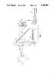
- FIG. 1illustrates an eye-position sensor in accordance with the present invention
- FIG. 2illustrates an enlarged portion of the eye-position sensor illustrated in FIG. 1;
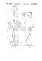
- FIG. 3illustrates a light sensor which forms part of the eye-position sensor illustrated in FIG. 1;
- FIG. 4illustrates a translucent character display and a spatial filter which forms part of the eye-position sensor illustrated in FIG. 1;
- FIG. 5illustrates in further detail control circuitry which forms part of the eye-position sensor illustrated in FIG. 1.
- the eye-position sensorcomprises a translucent alpha-numeric character display pad 10 in which the characters are illuminated e.g. by ambient light.
- the entire structure which is contained in a housing (not shown)can be positioned so that the eye 11 of a user such as a severely handicapped person, is focussed on the display pad 10 through a 34 millimeter diameter plastic lens 12 which is positioned a distance approximately equal to its focal length of 37.5 millimeters from the eye 11, less the virtual image distance behind its cornea 15. This distance ensures that the reflected rays which have passed through the lens 12 emerge substantially collateral.
- a light emitting diode LED) 13transmits 10 microwatts of infrared light at an 820 nanometer wavelength.
- the infrared lightis coupled from the light-emitting diode (LED) 13 through the lens 12 by an optical fiber 14, where it is transmitted towards the eye 11.
- the diameter of the illuminated area of the eye 11 from the infrared light from the fiber 14is restricted by the beam spread to about 6 millimeters. This aids the sensitivity of the system.
- the eye 11 of the userWhen the eye 11 of the user is focussed on one of the characters of the character display pad 10, light from the infrared source 13 is reflected from the cornea 15 of the eye 11 through the lens 12 to a spatial filter 20 having a square annular shape with overall dimensions of 3 millimeters and an annular thickness of 1 millimeter as shown in more detail in FIG. 4.
- the infrared light reflected from the eye 11 which passes through this filter 20is then coupled through a 6 millimeter focal length plastic lens 21. After passing through a window aperture 22 which is used to exclude extraneous light, the reflected light is detected by a light sensor 23.
- the lens 21is used to concentrate the light from the filter 20 onto the sensor 23.
- the aperture 22may be used to attaenuate unwanted reflections. If sufficient reflected light is available the elements 21 and 22 may be eliminated so that the light passing through the filter 20 falls directly on the sensor 23. Also the relative position of the filter 20 and lens 21 can be reversed.
- the filter 20provides two significant advantages. By restricting the light illuminating the sensor 23 to a square pattern, its response to eye movement is substantially linear. Also the filter 20 attenuates diffuse reflections from other parts of the eye 11. In some instances such reflections may be focussed in the center of the pattern. By utilizing an annular shaped filter, this center portion is blocked thereby further improving the response characteristics.
- the light sensor 23comprises a quadrantal array of contiguous photo detectors A, B, C, and D, each of which generates a signal current which is proportional to the illuminated area.
- the distance between the lens 21 and the surface of the sensor 23is such that a defocussed square annulus of light 24 from the spatial filter 20 is cast thereon. Because the illuminated area 24 is square and oriented in the same direction as the axes of the sensors 23, a horizontal X or vertical Y movement of the image will result in a substantially linear change in the output signal current from each of the photo detectors A, B, C, and D.
- the signals from the four quadrants A, B, C, and D of the sensor 23are coupled to control circuitry 25 which processes the signal so as to generate standard ASCII characters for controlling a printer 26.
- the control circuitry 25powers a selected one 28 of an 8 ⁇ 8 matrix of LEDs 27.
- the light from the one illuminated LED 28is reflected from a beam splitter 29, disposed between the display panel 10 and the lens 12, to the eye 11.
- the matrix of LEDs 27is disposed so that the selected LED 28 provides virtual highlighting of the alpha-numeric character on the display pad 10 on which the eye 11 is currently focussed.
- infrared lightis coupled from the LED 13 through the optical fiber 14 where it is transmitted so as to illuminate the eye 11.
- the LED 13is remote from the light sensor 23 to prevent electrical interference from the modulated drive current generated by a LED driver 30 which switches the LED on and off at a 1 kHz rate under control of a 1 kHz oscillator 31 in the control circuit 25.
- the use of a modulated signalpermits the use of a high gain low noise amplifier at the input to the control circuit 25, and substantial freedom from room lighting interference.
- the infrared light reflected from the cornea 15 of the eye 11generates four electrical signal currents A, B, C, and D, on the four quadrant light sensor 23. These signal currents are proportional to the incident light on them.
- These two signals X and Yare then coupled to a multiplexing A/D converter 34 through synchronous demodulators 33 and low pass filters 40.
- the demodulators 33are driven by the 1 Khz oscillator so that their output is in synchronization with that of the output from the LED 13 to produce output signals which are then digitized in the 8-bit analog-to-digital (A/D) converter 34.
- the 3 Hz low pass filters 40ensure that the control circuit 25 will respond only to eye movements.
- the output of the converter 34is fed to a microprocessor 35 which generates the standard 8-bit ASCII coded signals which are fed to the printer 26.
- an LED driver 36the selected character is given virtual highlighting through the 8 ⁇ 8 LED matrix 27.
- One feature of the present systemis the coaxiality of the illuminating radiation from the fiber 14 end, the axis of the photosensor array 23 and the axis of the display pad 10.
- the incident and reflected radiationare coaxial.
- Non-coaxial systems as described in the prior artreact very differently to the two directions of movement.
- One example of these systemsis described in "An Ocular Control Device For Use By The Severely Handicapped", by G. A. Rinard, and D. E. Rugg, 1976 Conference on Systems and Devices for the Diabled, Boston, Mass. June 1976.
- K. C. Anderson et alin "An Eye Position Controlled Typewriter" Digest 11th International Conference Med. Biol. Eng. 29:410-411, 1976.
- the present systemprovides immediate feedback to the user as to where the eye is focussed as determined by the system.
- the display pad 10is illuminated by ambient light from the front or back, black characters on a translucent white background are seen.
- the confirmatory illumination from the LED matrix 27is a colour (typically red or green) so that the user can readily adapt to the system when the latter is not accurate in its selection. For example, if the illuminated character is one space to the right of the character being focussed on, the user may shift his gaze by one space to the left thus achieving his desired choice.
- the angular distance between charactersis approximately 4 degrees and both positions are well within the visual span of the static eye.
- Character selectionis completed by the expiration of a dwell time period typically in the order of one second. After the dwell time has expired, control circuitry within the microprocessor 35 produces a sound on a loudspeaker or buzzer (not shown) to indicate the need for a next character selection. Alternatively, when the user has some elementary muscle control, he may be able to activate a switch to complete the selection.
- the display pad 10contains a rest space in its center. When the eye 11 gazes at this space the system takes no action and the user may ponder his next move without interference.
- electronic calibration under control of the microprocessor 35is achieved by the user gazing at a sequence of flashing lights located in the four corners of the display pad 10.
- the processed signal voltagesmodify the digital output of the microprocessor 35 to match the characteristics of the operator's eye and his exact eye position in reference to the optical sensor 23.
- the LED matrix 27may be located directly behind the display pad 10 while the infrared source, from the output of the fiber 14, may be in the position shown in the drawings for the LED matrix 27. This may be altered further so that the output end of the fiber 14 and the detectors 23 are interchanged. In each case however the spacial filter 20 is utilized to provide the square pattern of light on the photo detectors 23. With either of these alternative embodiments, unwanted reflections of infrared light from the lens 12 may occur. These may be reduced by angling the axis of the lens 12 about 6 degrees or by adding anti-reflective coating to the lens. In all embodiments however, it is important that the housing for the structure be held steady with respect to the eye such as by using a glasses frame and/or elastic strap, in conjunction with the bridge of the nose.
Landscapes
- Health & Medical Sciences (AREA)
- Life Sciences & Earth Sciences (AREA)
- Engineering & Computer Science (AREA)
- Heart & Thoracic Surgery (AREA)
- Molecular Biology (AREA)
- Biophysics (AREA)
- Ophthalmology & Optometry (AREA)
- Biomedical Technology (AREA)
- Human Computer Interaction (AREA)
- Medical Informatics (AREA)
- Physics & Mathematics (AREA)
- Surgery (AREA)
- Animal Behavior & Ethology (AREA)
- General Health & Medical Sciences (AREA)
- Public Health (AREA)
- Veterinary Medicine (AREA)
- Eye Examination Apparatus (AREA)
Abstract
Description
This invention relates to an eye-position sensor and more particularly to one that may be used in an eye-activated optical transducer which functions as a keyboard emulator for controlling such devices as a printer, monitor, or telephone modified with an eye-activated dialler and voice synthesizer.
Certain severely handicapped people can only reliably communicate through their eye movements. To facilitate this communication, typewriting devices have been developed which utilize eye-position control. An example of such a system is described in an article entitled "Eye-Controlled Communication Aids" by J. H. ten Kate et al., Medical Progress Through Technology 8:1-21, Springer-Verlag 1980. Eye tracking or positioning devices have also been described in U.S. Pat. No. 3,507,988 entitled "Narrow-Band, Single-Observer, Television Apparatus" by William S. Holmes, issued Apr. 21, 1970; U.S. Pat. No. 3,724,932 entitled "Eye Tracker And Method" by Tom N. Cornsweet et al issued Apr. 3, 1973. Reference to eye tracking devices is also made in U.S. Pat. No. 4,513,317 entitled "Retinally Stabilized Differential Resolution Television Display" by Carl F. Ruoff, issued Apr. 23, 1985. In general, these devices use a photo-sensor which detects the change in diffused or specular infrared reflections from the eye as it moves. A limiting factor in the detection of eye movements for communication purposes is the non-linearity of the transducer. As a result, eye tracking calibration has often been difficult, time consuming and inconsistent.
It has been discovered that a substantially linear analog signal output can be obtained from an eye-position sensor by utilizing optical componentry including a point source of light and a spatial filter between the eye and a quadrantal array of contiguous sensors so as to cast a substantially rectangular pattern of light on the sensors from the specularly reflected infrared light. With such an arrangement the eye acts as a convex mirror to reflect an image of the point source onto the sensor rather than an image of the eye itself.
In accordance with the present invention there is provided an eye-position sensor which provides signals representative of the X and Y coordinates of light reflected from the cornea of the eye. The sensor comprises a substantially point source of light for illuminating the eye and a light sensor which includes a quadrantal array of contiguous photo detectors each of which generates a signal which is proportional to its illuminated area. Also included is a lens for collimating the light from the point source of light reflected from the cornea of the eye onto the quadrantal array of contiguous photo detectors. The sensor also includes a spatial filter for shaping the distribution of light reflected from the eye to provide a rectangular pattern of light on the array. The spatial filter is oriented so that each corner of the rectangular pattern lies in a different quadrant of the array. The filter is disposed so that movement of the eye changes the position of the pattern illuminating the array. In a particular embodiment each of the photodetectors has a substantially square sensing surface, the size of which is preferably the same as that of the pattern being cast on the array.
An example embodiment of the invention will now be described with reference to the accompanying drawings in which:
FIG. 1 illustrates an eye-position sensor in accordance with the present invention;
FIG. 2 illustrates an enlarged portion of the eye-position sensor illustrated in FIG. 1;
FIG. 3 illustrates a light sensor which forms part of the eye-position sensor illustrated in FIG. 1;
FIG. 4 illustrates a translucent character display and a spatial filter which forms part of the eye-position sensor illustrated in FIG. 1; and
FIG. 5 illustrates in further detail control circuitry which forms part of the eye-position sensor illustrated in FIG. 1.
Referring to FIGS. 1 and 2, the eye-position sensor comprises a translucent alpha-numericcharacter display pad 10 in which the characters are illuminated e.g. by ambient light. The entire structure which is contained in a housing (not shown) can be positioned so that theeye 11 of a user such as a severely handicapped person, is focussed on thedisplay pad 10 through a 34 millimeter diameterplastic lens 12 which is positioned a distance approximately equal to its focal length of 37.5 millimeters from theeye 11, less the virtual image distance behind itscornea 15. This distance ensures that the reflected rays which have passed through thelens 12 emerge substantially collateral. A light emitting diode LED) 13 transmits 10 microwatts of infrared light at an 820 nanometer wavelength. The infrared light is coupled from the light-emitting diode (LED) 13 through thelens 12 by anoptical fiber 14, where it is transmitted towards theeye 11. The diameter of the illuminated area of theeye 11 from the infrared light from thefiber 14 is restricted by the beam spread to about 6 millimeters. This aids the sensitivity of the system.
When theeye 11 of the user is focussed on one of the characters of thecharacter display pad 10, light from theinfrared source 13 is reflected from thecornea 15 of theeye 11 through thelens 12 to aspatial filter 20 having a square annular shape with overall dimensions of 3 millimeters and an annular thickness of 1 millimeter as shown in more detail in FIG. 4. The infrared light reflected from theeye 11 which passes through thisfilter 20 is then coupled through a 6 millimeter focal lengthplastic lens 21. After passing through awindow aperture 22 which is used to exclude extraneous light, the reflected light is detected by alight sensor 23.
Thelens 21 is used to concentrate the light from thefilter 20 onto thesensor 23. Theaperture 22 may be used to attaenuate unwanted reflections. If sufficient reflected light is available theelements filter 20 falls directly on thesensor 23. Also the relative position of thefilter 20 andlens 21 can be reversed. Thefilter 20 provides two significant advantages. By restricting the light illuminating thesensor 23 to a square pattern, its response to eye movement is substantially linear. Also thefilter 20 attenuates diffuse reflections from other parts of theeye 11. In some instances such reflections may be focussed in the center of the pattern. By utilizing an annular shaped filter, this center portion is blocked thereby further improving the response characteristics.
As shown in FIG. 3, thelight sensor 23 comprises a quadrantal array of contiguous photo detectors A, B, C, and D, each of which generates a signal current which is proportional to the illuminated area. The distance between thelens 21 and the surface of thesensor 23 is such that a defocussed square annulus oflight 24 from thespatial filter 20 is cast thereon. Because theilluminated area 24 is square and oriented in the same direction as the axes of thesensors 23, a horizontal X or vertical Y movement of the image will result in a substantially linear change in the output signal current from each of the photo detectors A, B, C, and D. The signals from the four quadrants A, B, C, and D of thesensor 23 are coupled to controlcircuitry 25 which processes the signal so as to generate standard ASCII characters for controlling aprinter 26. Concurrently, thecontrol circuitry 25 powers a selected one 28 of an 8×8 matrix ofLEDs 27. The light from the oneilluminated LED 28 is reflected from abeam splitter 29, disposed between thedisplay panel 10 and thelens 12, to theeye 11. The matrix ofLEDs 27 is disposed so that the selectedLED 28 provides virtual highlighting of the alpha-numeric character on thedisplay pad 10 on which theeye 11 is currently focussed.
Referring to FIG. 5, infrared light is coupled from theLED 13 through theoptical fiber 14 where it is transmitted so as to illuminate theeye 11. TheLED 13 is remote from thelight sensor 23 to prevent electrical interference from the modulated drive current generated by aLED driver 30 which switches the LED on and off at a 1 kHz rate under control of a 1kHz oscillator 31 in thecontrol circuit 25. The use of a modulated signal permits the use of a high gain low noise amplifier at the input to thecontrol circuit 25, and substantial freedom from room lighting interference.
As explained previously, the infrared light reflected from thecornea 15 of theeye 11 generates four electrical signal currents A, B, C, and D, on the fourquadrant light sensor 23. These signal currents are proportional to the incident light on them. The electrical signal currents from thesensor 23 are amplified and processed in ananalog signal processor 32 which generates horizontal X and vertical Y coordinate voltages such that X=C+D-A-B and Y=A+C-B-D. These two signals X and Y are then coupled to a multiplexing A/D converter 34 throughsynchronous demodulators 33 andlow pass filters 40. Thedemodulators 33 are driven by the 1 Khz oscillator so that their output is in synchronization with that of the output from theLED 13 to produce output signals which are then digitized in the 8-bit analog-to-digital (A/D)converter 34. The 3 Hz low pass filters 40 ensure that thecontrol circuit 25 will respond only to eye movements. The output of theconverter 34 is fed to amicroprocessor 35 which generates the standard 8-bit ASCII coded signals which are fed to theprinter 26. Through anLED driver 36 the selected character is given virtual highlighting through the 8×8LED matrix 27.
One feature of the present system is the coaxiality of the illuminating radiation from thefiber 14 end, the axis of thephotosensor array 23 and the axis of thedisplay pad 10. When theeye 11 is gazing at the center of thedisplay pad 10, the incident and reflected radiation are coaxial. This permits the system to respond in comparable fashion to both horizontal X and vertical Y movements. Non-coaxial systems as described in the prior art, react very differently to the two directions of movement. One example of these systems is described in "An Ocular Control Device For Use By The Severely Handicapped", by G. A. Rinard, and D. E. Rugg, 1976 Conference on Systems and Devices for the Diabled, Boston, Mass. June 1976. Another example is described by K. C. Anderson et al in "An Eye Position Controlled Typewriter" Digest 11th International Conference Med. Biol. Eng. 29:410-411, 1976.
Utilizing theLED matrix 27, the present system provides immediate feedback to the user as to where the eye is focussed as determined by the system. When thedisplay pad 10 is illuminated by ambient light from the front or back, black characters on a translucent white background are seen. The confirmatory illumination from theLED matrix 27 is a colour (typically red or green) so that the user can readily adapt to the system when the latter is not accurate in its selection. For example, if the illuminated character is one space to the right of the character being focussed on, the user may shift his gaze by one space to the left thus achieving his desired choice. The angular distance between characters is approximately 4 degrees and both positions are well within the visual span of the static eye.
Character selection is completed by the expiration of a dwell time period typically in the order of one second. After the dwell time has expired, control circuitry within themicroprocessor 35 produces a sound on a loudspeaker or buzzer (not shown) to indicate the need for a next character selection. Alternatively, when the user has some elementary muscle control, he may be able to activate a switch to complete the selection.
Thedisplay pad 10 contains a rest space in its center. When theeye 11 gazes at this space the system takes no action and the user may ponder his next move without interference. Once the system is installed, electronic calibration under control of themicroprocessor 35, is achieved by the user gazing at a sequence of flashing lights located in the four corners of thedisplay pad 10. The processed signal voltages modify the digital output of themicroprocessor 35 to match the characteristics of the operator's eye and his exact eye position in reference to theoptical sensor 23.
In an alternative embodiment, theLED matrix 27 may be located directly behind thedisplay pad 10 while the infrared source, from the output of thefiber 14, may be in the position shown in the drawings for theLED matrix 27. This may be altered further so that the output end of thefiber 14 and thedetectors 23 are interchanged. In each case however thespacial filter 20 is utilized to provide the square pattern of light on thephoto detectors 23. With either of these alternative embodiments, unwanted reflections of infrared light from thelens 12 may occur. These may be reduced by angling the axis of thelens 12 about 6 degrees or by adding anti-reflective coating to the lens. In all embodiments however, it is important that the housing for the structure be held steady with respect to the eye such as by using a glasses frame and/or elastic strap, in conjunction with the bridge of the nose.
Claims (7)
1. In an eye-position sensor which provides a signal representative of the X and Y coordinates of light reflected from the cornea of an eye;
said eye-position sensor comprising:
a substantially point source of light for illuminating the eye; and
a light sensor including:
a quadrantal array of contiguous photo detectors each of which generates a signal which is proportional to the illuminated area thereof;
a lens for collimating the light from the point source of light reflected from the cornea of the eye, onto the quadrantal array of contiguous photo detectors;
said light sensor characterized by:
a spatial filter for providing a substantially rectangular pattern of light from said source which is specularly reflected from the eye onto the array so that each corner of the rectangular pattern lies in a different quadrant of the array;
the filter being disposed so that movement of the eye changes the position of the pattern illuminating the array.
2. An eye-position sensor as defined in claim 1 in which the light sensor is further characterized by:
each of the photodetectors has a sensing surface of a size at least as great as the substantially rectangular pattern of light which is incident thereon.
3. An eye-position sensor as defined in claim 2 in which the pattern of light from the filter is a substantially square annulus of light having substantially the same orientation as that of the array.
4. An eye-position sensor as defined in claim 3 which additionally comprises:
a display panel having an array of characters thereon;
said lens is disposed between the display panel and the eye for focusing the eye on the characters;
a partial light reflecting surface disposed between the lens and the display panel; and
an array of lights which produces a virtual image from reflections from the partial light reflecting surface;
the virtual image of each one of the array of lights being superimposed on respective ones of each of the characters on the display panel as seen by the eye to provide highlighting thereof.
5. An eye-position sensor as defined in claim 4 in which the point source of light is disposed in the middle of the lens, and the light sensor is disposed in the middle of the display panel, and in which the light sensor is further characterized by:
a further lens disposed between the spatial filter and the quadrantal array to condense the specularly reflected infrared light on the array.
6. An eye-position sensor as defined in claim 5 further comprising:
an aperture disposed between the further lens and the array for limiting spurious reflections from reaching said array.
7. An eye-position sensor as defined in claim 4 further comprising:
control means responsive to the signals from each of the photo sensors for illuminating one of the array of lights to produce a virtual image which is aligned with the character on the display board on which the eye is focused.
Priority Applications (1)
| Application Number | Priority Date | Filing Date | Title |
|---|---|---|---|
| US06/816,787US4720189A (en) | 1986-01-07 | 1986-01-07 | Eye-position sensor |
Applications Claiming Priority (1)
| Application Number | Priority Date | Filing Date | Title |
|---|---|---|---|
| US06/816,787US4720189A (en) | 1986-01-07 | 1986-01-07 | Eye-position sensor |
Publications (1)
| Publication Number | Publication Date |
|---|---|
| US4720189Atrue US4720189A (en) | 1988-01-19 |
Family
ID=25221605
Family Applications (1)
| Application Number | Title | Priority Date | Filing Date |
|---|---|---|---|
| US06/816,787Expired - LifetimeUS4720189A (en) | 1986-01-07 | 1986-01-07 | Eye-position sensor |
Country Status (1)
| Country | Link |
|---|---|
| US (1) | US4720189A (en) |
Cited By (88)
| Publication number | Priority date | Publication date | Assignee | Title |
|---|---|---|---|---|
| US4847486A (en)* | 1987-03-18 | 1989-07-11 | Rasaat | Electro-optical alertness monitoring apparatus |
| EP0433384A4 (en)* | 1988-08-24 | 1991-12-11 | Sebastiano Scarampi | Apparatus and method for monitoring television viewers |
| US5180907A (en)* | 1987-09-21 | 1993-01-19 | Per Udden | Method and apparatus for the measurement of rapid light variation superimposed on a slowly changing background light intensity |
| US5218387A (en)* | 1990-05-21 | 1993-06-08 | Nissan Motor Co., Ltd. | Eye position detecting apparatus |
| WO1993014692A1 (en)* | 1992-01-30 | 1993-08-05 | Mäk Technologies, Inc. | High speed eye tracking device and method |
| US5374193A (en)* | 1983-01-25 | 1994-12-20 | Trachtman; Joseph N. | Methods and apparatus for use in alpha training, EMG training and dichotic learning |
| US5406074A (en)* | 1994-02-07 | 1995-04-11 | Grisell; Ronald D. | Noninvasive, remote eye position and orientation measurement system using light beams normal to the surface of the eye |
| US5471542A (en)* | 1993-09-27 | 1995-11-28 | Ragland; Richard R. | Point-of-gaze tracker |
| GB2308212A (en)* | 1995-12-15 | 1997-06-18 | Christopher Wright | Visual keyboard communicator |
| EP0770370A3 (en)* | 1995-10-27 | 1997-07-02 | Ir Vision Inc | Apparatus for removing corneal tissue with infrared laser radiation |
| US5835613A (en)* | 1992-05-05 | 1998-11-10 | Automotive Technologies International, Inc. | Optical identification and monitoring system using pattern recognition for use with vehicles |
| US5844544A (en)* | 1994-06-17 | 1998-12-01 | H. K. Eyecan Ltd. | Visual communications apparatus employing eye-position monitoring |
| US5845000A (en)* | 1992-05-05 | 1998-12-01 | Automotive Technologies International, Inc. | Optical identification and monitoring system using pattern recognition for use with vehicles |
| US5997529A (en)* | 1996-10-28 | 1999-12-07 | Lasersight Technologies, Inc. | Compound astigmatic myopia or hyperopia correction by laser ablation |
| US5999895A (en)* | 1995-07-24 | 1999-12-07 | Forest; Donald K. | Sound operated menu method and apparatus |
| US6005549A (en)* | 1995-07-24 | 1999-12-21 | Forest; Donald K. | User interface method and apparatus |
| US6007202A (en)* | 1997-10-23 | 1999-12-28 | Lasersight Technologies, Inc. | Eye illumination system and method |
| US6090102A (en)* | 1997-05-12 | 2000-07-18 | Irvision, Inc. | Short pulse mid-infrared laser source for surgery |
| US6132424A (en)* | 1998-03-13 | 2000-10-17 | Lasersight Technologies Inc. | Smooth and uniform laser ablation apparatus and method |
| US6160536A (en)* | 1995-03-27 | 2000-12-12 | Forest; Donald K. | Dwell time indication method and apparatus |
| US6210169B1 (en) | 1997-01-31 | 2001-04-03 | Lasersight Technologies, Inc. | Device and method for simulating ophthalmic surgery |
| US6279946B1 (en) | 1998-06-09 | 2001-08-28 | Automotive Technologies International Inc. | Methods for controlling a system in a vehicle using a transmitting/receiving transducer and/or while compensating for thermal gradients |
| US6324453B1 (en) | 1998-12-31 | 2001-11-27 | Automotive Technologies International, Inc. | Methods for determining the identification and position of and monitoring objects in a vehicle |
| USRE37504E1 (en) | 1992-12-03 | 2002-01-08 | Lasersight Technologies, Inc. | Ophthalmic surgery method using non-contact scanning laser |
| US6393133B1 (en) | 1992-05-05 | 2002-05-21 | Automotive Technologies International, Inc. | Method and system for controlling a vehicular system based on occupancy of the vehicle |
| US6409718B1 (en) | 1998-02-03 | 2002-06-25 | Lasersight Technologies, Inc. | Device and method for correcting astigmatism by laser ablation |
| US6442465B2 (en) | 1992-05-05 | 2002-08-27 | Automotive Technologies International, Inc. | Vehicular component control systems and methods |
| US6450641B2 (en) | 1992-06-02 | 2002-09-17 | Lasersight Technologies, Inc. | Method of corneal analysis using a checkered placido apparatus |
| US6497701B2 (en) | 1999-04-30 | 2002-12-24 | Visx, Incorporated | Method and system for ablating surfaces with partially overlapping craters having consistent curvature |
| US6507779B2 (en) | 1995-06-07 | 2003-01-14 | Automotive Technologies International, Inc. | Vehicle rear seat monitor |
| US6517107B2 (en) | 1998-06-09 | 2003-02-11 | Automotive Technologies International, Inc. | Methods for controlling a system in a vehicle using a transmitting/receiving transducer and/or while compensating for thermal gradients |
| US6553296B2 (en) | 1995-06-07 | 2003-04-22 | Automotive Technologies International, Inc. | Vehicular occupant detection arrangements |
| US6716210B2 (en) | 1992-12-03 | 2004-04-06 | Lasersight Technologies, Inc. | Refractive surgical laser apparatus and method |
| US6724920B1 (en) | 2000-07-21 | 2004-04-20 | Trw Inc. | Application of human facial features recognition to automobile safety |
| US6772057B2 (en) | 1995-06-07 | 2004-08-03 | Automotive Technologies International, Inc. | Vehicular monitoring systems using image processing |
| US20040150514A1 (en)* | 2003-02-05 | 2004-08-05 | Newman Timothy J. | Vehicle situation alert system with eye gaze controlled alert signal generation |
| US6810135B1 (en) | 2000-06-29 | 2004-10-26 | Trw Inc. | Optimized human presence detection through elimination of background interference |
| US20040227699A1 (en)* | 2003-05-15 | 2004-11-18 | Mitchell Brian T. | Foveated display eye-tracking system and method |
| US6856873B2 (en) | 1995-06-07 | 2005-02-15 | Automotive Technologies International, Inc. | Vehicular monitoring systems using image processing |
| US20050073576A1 (en)* | 2002-01-25 | 2005-04-07 | Andreyko Aleksandr Ivanovich | Method for interactive television using foveal properties of the eyes of individual and grouped users and for protecting video information against the unauthorised access, dissemination and use thereof |
| US6903723B1 (en) | 1995-03-27 | 2005-06-07 | Donald K. Forest | Data entry method and apparatus |
| US6904347B1 (en) | 2000-06-29 | 2005-06-07 | Trw Inc. | Human presence detection, identification and tracking using a facial feature image sensing system for airbag deployment |
| US7110570B1 (en) | 2000-07-21 | 2006-09-19 | Trw Inc. | Application of human facial features recognition to automobile security and convenience |
| US20070280505A1 (en)* | 1995-06-07 | 2007-12-06 | Automotive Technologies International, Inc. | Eye Monitoring System and Method for Vehicular Occupants |
| US20080016463A1 (en)* | 2006-07-14 | 2008-01-17 | Madentec (Usa) Inc. | Systems and methods for using a switch to control a computer |
| US20080014159A1 (en)* | 2004-04-02 | 2008-01-17 | Allergan, Inc. | Therapy for melanin related afflictions |
| US20080069403A1 (en)* | 1995-06-07 | 2008-03-20 | Automotive Technologies International, Inc. | Face Monitoring System and Method for Vehicular Occupants |
| DE102011050942A1 (en) | 2010-06-16 | 2012-03-08 | Visteon Global Technologies, Inc. | Reconfigure an ad based on face / eye tracking |
| DE102012109622A1 (en) | 2011-10-12 | 2013-04-18 | Visteon Global Technologies, Inc. | Method for controlling a display component of an adaptive display system |
| US8632577B1 (en) | 2007-01-19 | 2014-01-21 | Lockheed Martin Corporation | Hybrid optical-electrical probes for stimulation of nerve or other animal tissue |
| US8709078B1 (en) | 2011-08-03 | 2014-04-29 | Lockheed Martin Corporation | Ocular implant with substantially constant retinal spacing for transmission of nerve-stimulation light |
| US8723790B1 (en) | 2008-09-26 | 2014-05-13 | Philip Raymond Schaefer | System and method for detecting facial gestures for control of an electronic device |
| US20140138544A1 (en)* | 2012-09-04 | 2014-05-22 | Innovega Inc. | Eye tracking system and related methods |
| US8945197B1 (en) | 2005-10-24 | 2015-02-03 | Lockheed Martin Corporation | Sight-restoring visual prosthetic and method using infrared nerve-stimulation light |
| US8956396B1 (en) | 2005-10-24 | 2015-02-17 | Lockheed Martin Corporation | Eye-tracking visual prosthetic and method |
| US9265458B2 (en) | 2012-12-04 | 2016-02-23 | Sync-Think, Inc. | Application of smooth pursuit cognitive testing paradigms to clinical drug development |
| US9380976B2 (en) | 2013-03-11 | 2016-07-05 | Sync-Think, Inc. | Optical neuroinformatics |
| US9684374B2 (en) | 2012-01-06 | 2017-06-20 | Google Inc. | Eye reflection image analysis |
| EP3157410A4 (en)* | 2014-06-20 | 2018-02-28 | Rambus Inc. | Systems and methods for lensed and lensless optical sensing |
| US20190171286A1 (en)* | 2015-03-23 | 2019-06-06 | Controlrad Systems Inc. | Eye Tracking System |
| US20200192530A1 (en)* | 2018-12-14 | 2020-06-18 | Nadia Masri | Methods, Systems, and Apparatus, for Receiving Persistent Responses to Online Surveys |
| US11223820B2 (en) | 2018-01-02 | 2022-01-11 | Lumus Ltd. | Augmented reality displays with active alignment and corresponding methods |
| USD941829S1 (en) | 2018-12-31 | 2022-01-25 | Perksy, Inc. | Display screen with graphical user interface |
| US20220252890A1 (en)* | 2016-12-31 | 2022-08-11 | Lumus Ltd | Eye tracker based on retinal imaging via light-guide optical element |
| US11454590B2 (en) | 2018-06-21 | 2022-09-27 | Lumus Ltd. | Measurement technique for refractive index inhomogeneity between plates of a lightguide optical element (LOE) |
| US11500143B2 (en) | 2017-01-28 | 2022-11-15 | Lumus Ltd. | Augmented reality imaging system |
| US11523092B2 (en) | 2019-12-08 | 2022-12-06 | Lumus Ltd. | Optical systems with compact image projector |
| US11531201B2 (en) | 2015-02-19 | 2022-12-20 | Lumus Ltd. | Compact head-mounted display system having uniform image |
| US11561435B2 (en) | 2017-07-19 | 2023-01-24 | Lumus Ltd. | LCOS illumination via LOE |
| US11561335B2 (en) | 2019-12-05 | 2023-01-24 | Lumus Ltd. | Light-guide optical element employing complementary coated partial reflectors, and light-guide optical element having reduced light scattering |
| US11567331B2 (en) | 2018-05-22 | 2023-01-31 | Lumus Ltd. | Optical system and method for improvement of light field uniformity |
| US11567316B2 (en) | 2016-10-09 | 2023-01-31 | Lumus Ltd. | Aperture multiplier with depolarizer |
| US11656472B2 (en) | 2017-10-22 | 2023-05-23 | Lumus Ltd. | Head-mounted augmented reality device employing an optical bench |
| US11719938B2 (en) | 2005-11-08 | 2023-08-08 | Lumus Ltd. | Polarizing optical system |
| US11747137B2 (en) | 2020-11-18 | 2023-09-05 | Lumus Ltd. | Optical-based validation of orientations of internal facets |
| US11747537B2 (en) | 2017-02-22 | 2023-09-05 | Lumus Ltd. | Light guide optical assembly |
| US11762169B2 (en) | 2017-12-03 | 2023-09-19 | Lumus Ltd. | Optical device alignment methods |
| US11822088B2 (en) | 2021-05-19 | 2023-11-21 | Lumus Ltd. | Active optical engine |
| US11914187B2 (en) | 2019-07-04 | 2024-02-27 | Lumus Ltd. | Image waveguide with symmetric beam multiplication |
| US11914161B2 (en) | 2019-06-27 | 2024-02-27 | Lumus Ltd. | Apparatus and methods for eye tracking based on eye imaging via light-guide optical element |
| US12019249B2 (en) | 2019-12-25 | 2024-06-25 | Lumus Ltd. | Optical systems and methods for eye tracking based on redirecting light from eye using an optical arrangement associated with a light-guide optical element |
| US12099214B2 (en) | 2018-08-26 | 2024-09-24 | Lumus Ltd. | Near-eye displays with scenery reflection suppression |
| US12111479B2 (en) | 2019-09-16 | 2024-10-08 | Lumus Ltd. | Image display system with beam multiplication |
| US12124037B2 (en) | 2020-05-24 | 2024-10-22 | Lumus Ltd. | Compound light-guide optical elements |
| US12124050B2 (en) | 2019-02-28 | 2024-10-22 | Lumus Ltd. | Compact collimated image projector |
| US12152994B2 (en) | 2020-04-30 | 2024-11-26 | Lumus Ltd. | Optical sample characterization |
| US12372799B2 (en) | 2020-05-12 | 2025-07-29 | Lumus Ltd. | Rotatable lightpipe |
| US12436062B2 (en) | 2022-08-01 | 2025-10-07 | Lumus Ltd. | Techniques for examination of light optical elements |
Citations (3)
| Publication number | Priority date | Publication date | Assignee | Title |
|---|---|---|---|---|
| US3507988A (en)* | 1966-09-15 | 1970-04-21 | Cornell Aeronautical Labor Inc | Narrow-band,single-observer,television apparatus |
| US3724932A (en)* | 1971-04-09 | 1973-04-03 | Stanford Research Inst | Eye tracker and method |
| US4513317A (en)* | 1982-09-28 | 1985-04-23 | The United States Of America As Represented By The Administrator Of The National Aeronautics And Space Administration | Retinally stabilized differential resolution television display |
- 1986
- 1986-01-07USUS06/816,787patent/US4720189A/ennot_activeExpired - Lifetime
Patent Citations (3)
| Publication number | Priority date | Publication date | Assignee | Title |
|---|---|---|---|---|
| US3507988A (en)* | 1966-09-15 | 1970-04-21 | Cornell Aeronautical Labor Inc | Narrow-band,single-observer,television apparatus |
| US3724932A (en)* | 1971-04-09 | 1973-04-03 | Stanford Research Inst | Eye tracker and method |
| US4513317A (en)* | 1982-09-28 | 1985-04-23 | The United States Of America As Represented By The Administrator Of The National Aeronautics And Space Administration | Retinally stabilized differential resolution television display |
Non-Patent Citations (2)
| Title |
|---|
| "Eye-Controlled Communication Aids" by J. H. ten Kate et al., Medical Progress Through Technology 8:1-21, Springer-Verlag, 1980. |
| Eye Controlled Communication Aids by J. H. ten Kate et al., Medical Progress Through Technology 8:1 21, Springer Verlag, 1980.* |
Cited By (112)
| Publication number | Priority date | Publication date | Assignee | Title |
|---|---|---|---|---|
| US5374193A (en)* | 1983-01-25 | 1994-12-20 | Trachtman; Joseph N. | Methods and apparatus for use in alpha training, EMG training and dichotic learning |
| US4847486A (en)* | 1987-03-18 | 1989-07-11 | Rasaat | Electro-optical alertness monitoring apparatus |
| US5180907A (en)* | 1987-09-21 | 1993-01-19 | Per Udden | Method and apparatus for the measurement of rapid light variation superimposed on a slowly changing background light intensity |
| EP0433384A4 (en)* | 1988-08-24 | 1991-12-11 | Sebastiano Scarampi | Apparatus and method for monitoring television viewers |
| US5218387A (en)* | 1990-05-21 | 1993-06-08 | Nissan Motor Co., Ltd. | Eye position detecting apparatus |
| US5430505A (en)* | 1992-01-30 | 1995-07-04 | Mak Technologies, Inc. | High speed eye tracking device and method |
| US5270748A (en)* | 1992-01-30 | 1993-12-14 | Mak Technologies, Inc. | High-speed eye tracking device and method |
| WO1993014692A1 (en)* | 1992-01-30 | 1993-08-05 | Mäk Technologies, Inc. | High speed eye tracking device and method |
| US5845000A (en)* | 1992-05-05 | 1998-12-01 | Automotive Technologies International, Inc. | Optical identification and monitoring system using pattern recognition for use with vehicles |
| US6442465B2 (en) | 1992-05-05 | 2002-08-27 | Automotive Technologies International, Inc. | Vehicular component control systems and methods |
| US5835613A (en)* | 1992-05-05 | 1998-11-10 | Automotive Technologies International, Inc. | Optical identification and monitoring system using pattern recognition for use with vehicles |
| US6141432A (en)* | 1992-05-05 | 2000-10-31 | Automotive Technologies International, Inc. | Optical identification |
| US6393133B1 (en) | 1992-05-05 | 2002-05-21 | Automotive Technologies International, Inc. | Method and system for controlling a vehicular system based on occupancy of the vehicle |
| US6450641B2 (en) | 1992-06-02 | 2002-09-17 | Lasersight Technologies, Inc. | Method of corneal analysis using a checkered placido apparatus |
| US6716210B2 (en) | 1992-12-03 | 2004-04-06 | Lasersight Technologies, Inc. | Refractive surgical laser apparatus and method |
| USRE37504E1 (en) | 1992-12-03 | 2002-01-08 | Lasersight Technologies, Inc. | Ophthalmic surgery method using non-contact scanning laser |
| US5471542A (en)* | 1993-09-27 | 1995-11-28 | Ragland; Richard R. | Point-of-gaze tracker |
| US5406074A (en)* | 1994-02-07 | 1995-04-11 | Grisell; Ronald D. | Noninvasive, remote eye position and orientation measurement system using light beams normal to the surface of the eye |
| US5844544A (en)* | 1994-06-17 | 1998-12-01 | H. K. Eyecan Ltd. | Visual communications apparatus employing eye-position monitoring |
| US20080030463A1 (en)* | 1995-03-27 | 2008-02-07 | Forest Donald K | User interface apparatus and method |
| US9535494B2 (en) | 1995-03-27 | 2017-01-03 | Donald K. Forest | Apparatus and method for selecting from a display |
| US6160536A (en)* | 1995-03-27 | 2000-12-12 | Forest; Donald K. | Dwell time indication method and apparatus |
| US6903723B1 (en) | 1995-03-27 | 2005-06-07 | Donald K. Forest | Data entry method and apparatus |
| US20070280505A1 (en)* | 1995-06-07 | 2007-12-06 | Automotive Technologies International, Inc. | Eye Monitoring System and Method for Vehicular Occupants |
| US7788008B2 (en) | 1995-06-07 | 2010-08-31 | Automotive Technologies International, Inc. | Eye monitoring system and method for vehicular occupants |
| US7570785B2 (en) | 1995-06-07 | 2009-08-04 | Automotive Technologies International, Inc. | Face monitoring system and method for vehicular occupants |
| US6553296B2 (en) | 1995-06-07 | 2003-04-22 | Automotive Technologies International, Inc. | Vehicular occupant detection arrangements |
| US20080069403A1 (en)* | 1995-06-07 | 2008-03-20 | Automotive Technologies International, Inc. | Face Monitoring System and Method for Vehicular Occupants |
| US6772057B2 (en) | 1995-06-07 | 2004-08-03 | Automotive Technologies International, Inc. | Vehicular monitoring systems using image processing |
| US6856873B2 (en) | 1995-06-07 | 2005-02-15 | Automotive Technologies International, Inc. | Vehicular monitoring systems using image processing |
| US6507779B2 (en) | 1995-06-07 | 2003-01-14 | Automotive Technologies International, Inc. | Vehicle rear seat monitor |
| US6005549A (en)* | 1995-07-24 | 1999-12-21 | Forest; Donald K. | User interface method and apparatus |
| US5999895A (en)* | 1995-07-24 | 1999-12-07 | Forest; Donald K. | Sound operated menu method and apparatus |
| US5782822A (en)* | 1995-10-27 | 1998-07-21 | Ir Vision, Inc. | Method and apparatus for removing corneal tissue with infrared laser radiation |
| EP0770370A3 (en)* | 1995-10-27 | 1997-07-02 | Ir Vision Inc | Apparatus for removing corneal tissue with infrared laser radiation |
| GB2308212A (en)* | 1995-12-15 | 1997-06-18 | Christopher Wright | Visual keyboard communicator |
| US5997529A (en)* | 1996-10-28 | 1999-12-07 | Lasersight Technologies, Inc. | Compound astigmatic myopia or hyperopia correction by laser ablation |
| US6210169B1 (en) | 1997-01-31 | 2001-04-03 | Lasersight Technologies, Inc. | Device and method for simulating ophthalmic surgery |
| US6090102A (en)* | 1997-05-12 | 2000-07-18 | Irvision, Inc. | Short pulse mid-infrared laser source for surgery |
| US6334683B2 (en) | 1997-10-23 | 2002-01-01 | Lasersight Technologies, Inc. | Eye illumination system and method |
| US6007202A (en)* | 1997-10-23 | 1999-12-28 | Lasersight Technologies, Inc. | Eye illumination system and method |
| US6193373B1 (en) | 1997-10-23 | 2001-02-27 | Lasersight Technologies, Inc. | Eye illumination system and method |
| US6409718B1 (en) | 1998-02-03 | 2002-06-25 | Lasersight Technologies, Inc. | Device and method for correcting astigmatism by laser ablation |
| US6132424A (en)* | 1998-03-13 | 2000-10-17 | Lasersight Technologies Inc. | Smooth and uniform laser ablation apparatus and method |
| US6517107B2 (en) | 1998-06-09 | 2003-02-11 | Automotive Technologies International, Inc. | Methods for controlling a system in a vehicle using a transmitting/receiving transducer and/or while compensating for thermal gradients |
| US6279946B1 (en) | 1998-06-09 | 2001-08-28 | Automotive Technologies International Inc. | Methods for controlling a system in a vehicle using a transmitting/receiving transducer and/or while compensating for thermal gradients |
| US6324453B1 (en) | 1998-12-31 | 2001-11-27 | Automotive Technologies International, Inc. | Methods for determining the identification and position of and monitoring objects in a vehicle |
| US6497701B2 (en) | 1999-04-30 | 2002-12-24 | Visx, Incorporated | Method and system for ablating surfaces with partially overlapping craters having consistent curvature |
| US6810135B1 (en) | 2000-06-29 | 2004-10-26 | Trw Inc. | Optimized human presence detection through elimination of background interference |
| US6904347B1 (en) | 2000-06-29 | 2005-06-07 | Trw Inc. | Human presence detection, identification and tracking using a facial feature image sensing system for airbag deployment |
| US6724920B1 (en) | 2000-07-21 | 2004-04-20 | Trw Inc. | Application of human facial features recognition to automobile safety |
| US7110570B1 (en) | 2000-07-21 | 2006-09-19 | Trw Inc. | Application of human facial features recognition to automobile security and convenience |
| US7950029B2 (en) | 2002-01-25 | 2011-05-24 | Aleksandr Ivanovich Andreyko | Method for interactive television using foveal properties of the eyes of individual and grouped users and for protecting video information against the unauthorized access, dissemination and use thereof |
| US20050073576A1 (en)* | 2002-01-25 | 2005-04-07 | Andreyko Aleksandr Ivanovich | Method for interactive television using foveal properties of the eyes of individual and grouped users and for protecting video information against the unauthorised access, dissemination and use thereof |
| US20040150514A1 (en)* | 2003-02-05 | 2004-08-05 | Newman Timothy J. | Vehicle situation alert system with eye gaze controlled alert signal generation |
| US6859144B2 (en) | 2003-02-05 | 2005-02-22 | Delphi Technologies, Inc. | Vehicle situation alert system with eye gaze controlled alert signal generation |
| US7872635B2 (en) | 2003-05-15 | 2011-01-18 | Optimetrics, Inc. | Foveated display eye-tracking system and method |
| US20040227699A1 (en)* | 2003-05-15 | 2004-11-18 | Mitchell Brian T. | Foveated display eye-tracking system and method |
| US20080014159A1 (en)* | 2004-04-02 | 2008-01-17 | Allergan, Inc. | Therapy for melanin related afflictions |
| US8945197B1 (en) | 2005-10-24 | 2015-02-03 | Lockheed Martin Corporation | Sight-restoring visual prosthetic and method using infrared nerve-stimulation light |
| US8956396B1 (en) | 2005-10-24 | 2015-02-17 | Lockheed Martin Corporation | Eye-tracking visual prosthetic and method |
| US11719938B2 (en) | 2005-11-08 | 2023-08-08 | Lumus Ltd. | Polarizing optical system |
| US20080016463A1 (en)* | 2006-07-14 | 2008-01-17 | Madentec (Usa) Inc. | Systems and methods for using a switch to control a computer |
| US8632577B1 (en) | 2007-01-19 | 2014-01-21 | Lockheed Martin Corporation | Hybrid optical-electrical probes for stimulation of nerve or other animal tissue |
| US8723790B1 (en) | 2008-09-26 | 2014-05-13 | Philip Raymond Schaefer | System and method for detecting facial gestures for control of an electronic device |
| US9367127B1 (en) | 2008-09-26 | 2016-06-14 | Philip Raymond Schaefer | System and method for detecting facial gestures for control of an electronic device |
| DE102011050942A1 (en) | 2010-06-16 | 2012-03-08 | Visteon Global Technologies, Inc. | Reconfigure an ad based on face / eye tracking |
| US8709078B1 (en) | 2011-08-03 | 2014-04-29 | Lockheed Martin Corporation | Ocular implant with substantially constant retinal spacing for transmission of nerve-stimulation light |
| DE102012109622A1 (en) | 2011-10-12 | 2013-04-18 | Visteon Global Technologies, Inc. | Method for controlling a display component of an adaptive display system |
| US9684374B2 (en) | 2012-01-06 | 2017-06-20 | Google Inc. | Eye reflection image analysis |
| US20140138544A1 (en)* | 2012-09-04 | 2014-05-22 | Innovega Inc. | Eye tracking system and related methods |
| US9040923B2 (en)* | 2012-09-04 | 2015-05-26 | Innovega, Inc. | Eye tracking system and related methods |
| US9265458B2 (en) | 2012-12-04 | 2016-02-23 | Sync-Think, Inc. | Application of smooth pursuit cognitive testing paradigms to clinical drug development |
| US9380976B2 (en) | 2013-03-11 | 2016-07-05 | Sync-Think, Inc. | Optical neuroinformatics |
| EP3157410A4 (en)* | 2014-06-20 | 2018-02-28 | Rambus Inc. | Systems and methods for lensed and lensless optical sensing |
| US10188289B2 (en) | 2014-06-20 | 2019-01-29 | Rambus Inc. | Systems and methods for lensed and lensless optical sensing |
| US10653313B2 (en) | 2014-06-20 | 2020-05-19 | Rambus Inc. | Systems and methods for lensed and lensless optical sensing of binary scenes |
| US11531201B2 (en) | 2015-02-19 | 2022-12-20 | Lumus Ltd. | Compact head-mounted display system having uniform image |
| US20190171286A1 (en)* | 2015-03-23 | 2019-06-06 | Controlrad Systems Inc. | Eye Tracking System |
| US10948984B2 (en)* | 2015-03-23 | 2021-03-16 | Controlrad Systems Inc. | Calibration of an eye tracking system |
| US20220155862A1 (en)* | 2015-03-23 | 2022-05-19 | Controlrad, Inc. | Eye Tracking System |
| US11567316B2 (en) | 2016-10-09 | 2023-01-31 | Lumus Ltd. | Aperture multiplier with depolarizer |
| US20220252890A1 (en)* | 2016-12-31 | 2022-08-11 | Lumus Ltd | Eye tracker based on retinal imaging via light-guide optical element |
| US11747635B2 (en)* | 2016-12-31 | 2023-09-05 | Lumus Ltd. | Eye tracker based on retinal imaging via light-guide optical element |
| US11500143B2 (en) | 2017-01-28 | 2022-11-15 | Lumus Ltd. | Augmented reality imaging system |
| US11747537B2 (en) | 2017-02-22 | 2023-09-05 | Lumus Ltd. | Light guide optical assembly |
| US11561435B2 (en) | 2017-07-19 | 2023-01-24 | Lumus Ltd. | LCOS illumination via LOE |
| US11966062B2 (en) | 2017-10-22 | 2024-04-23 | Lumus Ltd. | Head-mounted augmented reality device employing an optical bench |
| US11656472B2 (en) | 2017-10-22 | 2023-05-23 | Lumus Ltd. | Head-mounted augmented reality device employing an optical bench |
| US11762169B2 (en) | 2017-12-03 | 2023-09-19 | Lumus Ltd. | Optical device alignment methods |
| US11223820B2 (en) | 2018-01-02 | 2022-01-11 | Lumus Ltd. | Augmented reality displays with active alignment and corresponding methods |
| US11567331B2 (en) | 2018-05-22 | 2023-01-31 | Lumus Ltd. | Optical system and method for improvement of light field uniformity |
| US11454590B2 (en) | 2018-06-21 | 2022-09-27 | Lumus Ltd. | Measurement technique for refractive index inhomogeneity between plates of a lightguide optical element (LOE) |
| US12099214B2 (en) | 2018-08-26 | 2024-09-24 | Lumus Ltd. | Near-eye displays with scenery reflection suppression |
| US20200192530A1 (en)* | 2018-12-14 | 2020-06-18 | Nadia Masri | Methods, Systems, and Apparatus, for Receiving Persistent Responses to Online Surveys |
| US11579750B2 (en)* | 2018-12-14 | 2023-02-14 | Perksy, Inc. | Methods, systems, and apparatus, for receiving persistent responses to online surveys |
| USD941829S1 (en) | 2018-12-31 | 2022-01-25 | Perksy, Inc. | Display screen with graphical user interface |
| USD1066361S1 (en) | 2018-12-31 | 2025-03-11 | Perksy, Inc. | Display screen with a graphical user interface |
| US12124050B2 (en) | 2019-02-28 | 2024-10-22 | Lumus Ltd. | Compact collimated image projector |
| US11914161B2 (en) | 2019-06-27 | 2024-02-27 | Lumus Ltd. | Apparatus and methods for eye tracking based on eye imaging via light-guide optical element |
| US11914187B2 (en) | 2019-07-04 | 2024-02-27 | Lumus Ltd. | Image waveguide with symmetric beam multiplication |
| US12111479B2 (en) | 2019-09-16 | 2024-10-08 | Lumus Ltd. | Image display system with beam multiplication |
| US11561335B2 (en) | 2019-12-05 | 2023-01-24 | Lumus Ltd. | Light-guide optical element employing complementary coated partial reflectors, and light-guide optical element having reduced light scattering |
| US11729359B2 (en) | 2019-12-08 | 2023-08-15 | Lumus Ltd. | Optical systems with compact image projector |
| US11523092B2 (en) | 2019-12-08 | 2022-12-06 | Lumus Ltd. | Optical systems with compact image projector |
| US12019249B2 (en) | 2019-12-25 | 2024-06-25 | Lumus Ltd. | Optical systems and methods for eye tracking based on redirecting light from eye using an optical arrangement associated with a light-guide optical element |
| US12152994B2 (en) | 2020-04-30 | 2024-11-26 | Lumus Ltd. | Optical sample characterization |
| US12372799B2 (en) | 2020-05-12 | 2025-07-29 | Lumus Ltd. | Rotatable lightpipe |
| US12124037B2 (en) | 2020-05-24 | 2024-10-22 | Lumus Ltd. | Compound light-guide optical elements |
| US11747137B2 (en) | 2020-11-18 | 2023-09-05 | Lumus Ltd. | Optical-based validation of orientations of internal facets |
| US11822088B2 (en) | 2021-05-19 | 2023-11-21 | Lumus Ltd. | Active optical engine |
| US12436062B2 (en) | 2022-08-01 | 2025-10-07 | Lumus Ltd. | Techniques for examination of light optical elements |
Similar Documents
| Publication | Publication Date | Title |
|---|---|---|
| US4720189A (en) | Eye-position sensor | |
| US5583795A (en) | Apparatus for measuring eye gaze and fixation duration, and method therefor | |
| US11883101B2 (en) | System and method for enabling communication through eye feedback | |
| US6433760B1 (en) | Head mounted display with eyetracking capability | |
| US5654741A (en) | Spatial light modulator display pointing device | |
| US3712716A (en) | Eye tracker | |
| US4845641A (en) | Method of forming a synthetic image in simulation system for attachment of spectacles | |
| US11675429B2 (en) | Calibration, customization, and improved user experience for bionic lenses | |
| US4823170A (en) | Line of sight measuring system | |
| US4946271A (en) | Optical device | |
| KR940009817A (en) | Pointing device using photo detector | |
| ES2191752T3 (en) | PICTURE PROCESS SYSTEM USING AN ANALOG CONTROL LEVER. | |
| WO2004066097A2 (en) | Gaze tracking system and method | |
| CA1148737A (en) | Artificial horizon device | |
| WO1999005988A2 (en) | An eye tracker using an off-axis, ring illumination source | |
| US5191411A (en) | Laser driven optical communication apparatus | |
| CA1237179A (en) | Eye-position sensor | |
| Iwamoto et al. | High resolution, wide view angle head mounted display using eye movement tracking: system structure and evaluation experiments | |
| JPH02194485A (en) | fingerprint data entry device | |
| JPH11249588A (en) | Head mounted display | |
| DE69021581D1 (en) | COMMUNICATION DEVICE. | |
| US11657134B2 (en) | Eye contact detection device | |
| KR19990021540A (en) | Input device using eye's eye angle | |
| JP2507913B2 (en) | Eye movement tracking type visual presentation device by projection method | |
| Merchant | Fixation point measurement by the oculometer technique |
Legal Events
| Date | Code | Title | Description |
|---|---|---|---|
| AS | Assignment | Owner name:BELL-NORTHERN RESEARCH LTD., PO BOX 3511, STATION Free format text:ASSIGNMENT OF ASSIGNORS INTEREST.;ASSIGNORS:HEYNEN, JAN;KAHN, DAVID A.;REEL/FRAME:004505/0365 Effective date:19851219 Owner name:NORTHERN TELECOM LIMITED P.O. BOX 6123, STATION A, Free format text:ASSIGNMENT OF ASSIGNORS INTEREST.;ASSIGNOR:BELL-NORTHERN RESEARCH LTD.;REEL/FRAME:004523/0242 Effective date:19851219 | |
| STCF | Information on status: patent grant | Free format text:PATENTED CASE | |
| FPAY | Fee payment | Year of fee payment:4 | |
| FPAY | Fee payment | Year of fee payment:8 | |
| FPAY | Fee payment | Year of fee payment:12 |