US4720142A - Variable back stop - Google Patents
Variable back stopDownload PDFInfo
- Publication number
- US4720142A US4720142AUS06/850,508US85050886AUS4720142AUS 4720142 AUS4720142 AUS 4720142AUS 85050886 AUS85050886 AUS 85050886AUS 4720142 AUS4720142 AUS 4720142A
- Authority
- US
- United States
- Prior art keywords
- stop
- chair
- plates
- control pin
- motion
- Prior art date
- Legal status (The legal status is an assumption and is not a legal conclusion. Google has not performed a legal analysis and makes no representation as to the accuracy of the status listed.)
- Expired - Lifetime
Links
- 241001049176CharisSpecies0.000abstract1
- 235000005612Grewia tenaxNutrition0.000abstract1
- 230000009471actionEffects0.000description8
- 230000013011matingEffects0.000description6
- 210000005069earsAnatomy0.000description5
- 238000010276constructionMethods0.000description3
- 239000002184metalSubstances0.000description2
- 238000012986modificationMethods0.000description2
- 230000004048modificationEffects0.000description2
- 239000004677NylonSubstances0.000description1
- 239000003831antifriction materialSubstances0.000description1
- 238000004519manufacturing processMethods0.000description1
- 230000007246mechanismEffects0.000description1
- 238000000034methodMethods0.000description1
- 229920001778nylonPolymers0.000description1
- 230000008569processEffects0.000description1
- 239000012858resilient materialSubstances0.000description1
- 230000000452restraining effectEffects0.000description1
- 230000000717retained effectEffects0.000description1
- 239000011435rockSubstances0.000description1
- 238000003466weldingMethods0.000description1
Images


Classifications
- A—HUMAN NECESSITIES
- A47—FURNITURE; DOMESTIC ARTICLES OR APPLIANCES; COFFEE MILLS; SPICE MILLS; SUCTION CLEANERS IN GENERAL
- A47C—CHAIRS; SOFAS; BEDS
- A47C7/00—Parts, details, or accessories of chairs or stools
- A47C7/36—Supports for the head or the back
- A47C7/40—Supports for the head or the back for the back
- A47C7/46—Supports for the head or the back for the back with special, e.g. adjustable, lumbar region support profile; "Ackerblom" profile chairs
- A—HUMAN NECESSITIES
- A47—FURNITURE; DOMESTIC ARTICLES OR APPLIANCES; COFFEE MILLS; SPICE MILLS; SUCTION CLEANERS IN GENERAL
- A47C—CHAIRS; SOFAS; BEDS
- A47C1/00—Chairs adapted for special purposes
- A47C1/02—Reclining or easy chairs
- A47C1/031—Reclining or easy chairs having coupled concurrently adjustable supporting parts
- A47C1/032—Reclining or easy chairs having coupled concurrently adjustable supporting parts the parts being movably-coupled seat and back-rest
- A47C1/03255—Reclining or easy chairs having coupled concurrently adjustable supporting parts the parts being movably-coupled seat and back-rest with a central column, e.g. rocking office chairs
- A—HUMAN NECESSITIES
- A47—FURNITURE; DOMESTIC ARTICLES OR APPLIANCES; COFFEE MILLS; SPICE MILLS; SUCTION CLEANERS IN GENERAL
- A47C—CHAIRS; SOFAS; BEDS
- A47C1/00—Chairs adapted for special purposes
- A47C1/02—Reclining or easy chairs
- A47C1/031—Reclining or easy chairs having coupled concurrently adjustable supporting parts
- A47C1/032—Reclining or easy chairs having coupled concurrently adjustable supporting parts the parts being movably-coupled seat and back-rest
- A47C1/03261—Reclining or easy chairs having coupled concurrently adjustable supporting parts the parts being movably-coupled seat and back-rest characterised by elastic means
- A47C1/03266—Reclining or easy chairs having coupled concurrently adjustable supporting parts the parts being movably-coupled seat and back-rest characterised by elastic means with adjustable elasticity
- A—HUMAN NECESSITIES
- A47—FURNITURE; DOMESTIC ARTICLES OR APPLIANCES; COFFEE MILLS; SPICE MILLS; SUCTION CLEANERS IN GENERAL
- A47C—CHAIRS; SOFAS; BEDS
- A47C1/00—Chairs adapted for special purposes
- A47C1/02—Reclining or easy chairs
- A47C1/031—Reclining or easy chairs having coupled concurrently adjustable supporting parts
- A47C1/032—Reclining or easy chairs having coupled concurrently adjustable supporting parts the parts being movably-coupled seat and back-rest
- A47C1/03261—Reclining or easy chairs having coupled concurrently adjustable supporting parts the parts being movably-coupled seat and back-rest characterised by elastic means
- A47C1/03272—Reclining or easy chairs having coupled concurrently adjustable supporting parts the parts being movably-coupled seat and back-rest characterised by elastic means with coil springs
- A47C1/03274—Reclining or easy chairs having coupled concurrently adjustable supporting parts the parts being movably-coupled seat and back-rest characterised by elastic means with coil springs of torsion type
- A—HUMAN NECESSITIES
- A47—FURNITURE; DOMESTIC ARTICLES OR APPLIANCES; COFFEE MILLS; SPICE MILLS; SUCTION CLEANERS IN GENERAL
- A47C—CHAIRS; SOFAS; BEDS
- A47C1/00—Chairs adapted for special purposes
- A47C1/02—Reclining or easy chairs
- A47C1/031—Reclining or easy chairs having coupled concurrently adjustable supporting parts
- A47C1/032—Reclining or easy chairs having coupled concurrently adjustable supporting parts the parts being movably-coupled seat and back-rest
- A47C1/03261—Reclining or easy chairs having coupled concurrently adjustable supporting parts the parts being movably-coupled seat and back-rest characterised by elastic means
- A47C1/03277—Reclining or easy chairs having coupled concurrently adjustable supporting parts the parts being movably-coupled seat and back-rest characterised by elastic means with bar or leaf springs
- A—HUMAN NECESSITIES
- A47—FURNITURE; DOMESTIC ARTICLES OR APPLIANCES; COFFEE MILLS; SPICE MILLS; SUCTION CLEANERS IN GENERAL
- A47C—CHAIRS; SOFAS; BEDS
- A47C3/00—Chairs characterised by structural features; Chairs or stools with rotatable or vertically-adjustable seats
- A47C3/12—Chairs characterised by structural features; Chairs or stools with rotatable or vertically-adjustable seats with shell-shape seat and back-rest unit, e.g. having arm rests
- A—HUMAN NECESSITIES
- A47—FURNITURE; DOMESTIC ARTICLES OR APPLIANCES; COFFEE MILLS; SPICE MILLS; SUCTION CLEANERS IN GENERAL
- A47C—CHAIRS; SOFAS; BEDS
- A47C3/00—Chairs characterised by structural features; Chairs or stools with rotatable or vertically-adjustable seats
- A47C3/18—Chairs or stools with rotatable seat
- A—HUMAN NECESSITIES
- A47—FURNITURE; DOMESTIC ARTICLES OR APPLIANCES; COFFEE MILLS; SPICE MILLS; SUCTION CLEANERS IN GENERAL
- A47C—CHAIRS; SOFAS; BEDS
- A47C3/00—Chairs characterised by structural features; Chairs or stools with rotatable or vertically-adjustable seats
- A47C3/20—Chairs or stools with vertically-adjustable seats
- A47C3/24—Chairs or stools with vertically-adjustable seats with vertical spindle
- A47C3/245—Chairs or stools with vertically-adjustable seats with vertical spindle resiliently supported
Definitions
- the present inventionrelates to articulated furniture articles, and in particular to a variable back stop for seating, and the like.
- Articulated seatingsuch as tilt back chairs, and other furniture articles of the type having at least two, mutually adjustable portions, are used extensively in office environments.
- the mutually adjustable portions of the seatingare normally interconnected by a controller or control, which mechanically adjusts the mutual orientation of the various adjustable seating portions.
- Seating controlsusually include springs which bias the seating into a normal or upright position.
- Such controlsalso typically include some type of adjustment device to vary the biasing force which resists movement of the adjustable portions of the seating from their normal position.
- a stop assemblymay be provided in articulated seating to selectively limit the amount of movement permitted between the mutually adjustable portions of the seating. For instance, in tilt back chairs, and other similar seating, a stop assembly may be used to limit the rearward tilting movement of the chair back. Because users have widely differing physical characteristics, including weight, shape, strength, and the like, and perform a variety of different seated tasks, the ultimate or most comfortable maximum tilt angle of the chair back varies from one individual to another. Also, the most comfortable back position will vary for any particular individual depending upon the task being performed. The variable back stop permits the chair to be adjusted to accommodate the particular individual, as well as the specific task with which the seating is used.
- Task seatingA type of seating known as "task seating” is becoming increasingly popular for use at computer terminals, and other similar work stations.
- Task seatingis typically used by several different individuals on a regular basis, and must be readily adaptable for all types of applications and tasks.
- the ability to adjust the maximum rearward tilt position of a chair backis clearly a preferred feature in all types of articulating seating.
- adjustment capabilitiesare now considered to be an important factor in the overall marketability of the chair. It is particularly critical that adjustment of the maximum tilt position be capable of being made quickly and easily by the workers or users themselves.
- such adjustmentcan be made by the user, while actually sitting on the chair, so that the maximum back tilt position can be made initially by a seated user, quickly tested, and easily readjusted if necessary, to attain maximum comfort.
- the maximum back tilt positionbe adjustable throughout a broad range, so as to be able to adapt the chair into a comfortable configuration for a wide variety of different persons and tasks.
- One aspect of the present inventionis to provide a positive, mechanical variable back stop for articulated seating, such as tilt back chairs, and the like, of the type having a stationary support and a back which tilts with respect to the support.
- the variable back stopcomprises a stop surface, and at least one stop member, which are located on associated portions of the chair support and the chair back.
- the stop surface and the stop memberare mutually positioned such that rearward tilting of the chair back generally converges the stop surface and stop member along a line of motion, and forward tilting of the chair back generally diverges the same.
- the stop memberhas an engaged position, wherein at least a portion of the stop member is positioned in the line of motion to abut the stop surface upon rearward tilting of the chair back, and a disengaged position, wherein the stop member is positioned outside of the path of motion to avoid abutting the stop surface upon rearward tilting of the chair back.
- An actuatorshifts the stop member between the engaged and disengaged positions to selectively stop or limit rearward tilting of the chair back.
- a plurality of stop membersare provided in a stacked arrangement to limit chair back tilt at a number of different positions, and an actuator is provided to manipulate the variable back stop from a seated position in the chair.
- the principal objects of the present inventionare to provide a mechanical, variable back stop that has a positive type of stopping action, and is extremely reliable.
- the stopis particularly adapted for controlling the rearward tilting action of a tilt back type of chair, and can be manipulated to limit chair back tilt at a wide variety of different positions to accommodate different persons and tasks.
- the variable back stopis designed to be easily adjusted from a seated position within the chair, so that the maximum back tilt position can be quickly tested and easily readjusted if necessary, to obtain maximum comfort.
- the variable back stophas a cushion arrangement that provides a gentle stopping action. Even while the variable back stop is set, it permits the control to bias the chair back to the fully upright position for improved user comfort and back support, particularly when exiting the chair.
- the variable back stophas a rather uncomplicated construction, is efficient in use, economical to manufacture, capable of a long operating life, and particularly adapted for the proposed use.
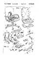
- FIG. 1is a perspective view of a chair, with portions thereof broken away to reveal a variable back stop embodying the present invention.
- FIG. 2is an exploded perspective view of the chair.
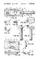
- FIG. 3is a top plan view of a control portion of the chair.
- FIG. 4is a vertical cross-sectional view of the control, taken along the line IV--IV of FIG. 3.
- FIG. 5is an exploded, top plan view of an actuator portion of the variable back stop.
- FIG. 6is an exploded, side elevational view of the actuator.
- FIG. 7is a fragmentary, vertical cross-sectional view of the control.
- FIG. 8is a front elevational view of a toggle button portion of the actuator.
- FIG. 9is a perspective view of a control arm portion of the variable back stop.
- FIG. 10is is a fragmentary, top plan view of the variable back stop, with portions thereof broken away to reveal internal construction.
- FIG. 11is an enlarged, fragmentary, top plan view of the variable back stop, shown in an engaged position.
- FIG. 12is an enlarged, fragmentary, top plan view of the variable back stop, shown in a disengaged position.
- FIG. 13is a rear elevational view of the variable back stop, taken along the line XIII--XIII of FIG. 3.
- FIG. 14is a vertical cross-sectional view of the countrol, taken along the line XIV--XIV of FIG. 3.
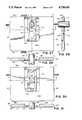
- FIG. 15is a top plan view of a stop plate assembly portion of the variable back stop.
- FIG. 16is a side elevational view of the stop plate assembly.
- FIG. 17is a top plan view of a pivot support portion of the stop plate assembly.
- FIG. 18is a side elevational view of the pivot support.
- FIG. 19is a front elevational view of the pivot support.
- FIG. 20is a front elevational view of a control pin portion of the stop plate assembly.
- FIG. 21is a side elevational view of the control pin.
- FIG. 22is a top plan view of the control pin.
- FIG. 23is a top plan view of a pin bearing portion of the stop plate assembly.
- FIG. 24is a side elevational view of the pin bearing.
- FIG. 25is a front elevational view of the pin bearing.
- FIG. 26is a vertical cross-sectional view of the pin bearing, taken the line XXVI--XXVI of FIG. 25.
- FIG. 27is an enlarged, top plan view of a stop plate portion of the stop plate assembly, wherein the control pin is shown in a released position.
- FIG. 28is a vertical cross-sectional view of the stop plate, taken along the line XXVIII--XXVIII of FIG. 27.
- FIG. 29is a vertical cross-sectional view of the stop plate, taken along the line XXIX--XXIX of FIG. 27.
- FIG. 30is a top plan view of the stop plate, with the control pin shown in an intermediate position.
- FIG. 31is a vertical cross-sectional view of the stop plate, taken along the line XXXI--XXXI of FIG. 30.
- FIG. 32is a vertical cross-sectional view of the variable back stop, shown with the stop plates in the disengaged position, and the chair back in a fully upright position.
- FIG. 33is a vertical cross-sectional view of the variable back stop, shown with the stop plates in the disengaged position, and the chair back in a rearwardly tilted position.
- FIG. 34is a vertical cross-sectional view of the variable back stop, shown with the chair back in the rearwardly tilted position illustrated in FIG. 34, and with the three uppermost stop plates shifted into the engaged position.
- FIG. 35is a vertical cross-sectional view of the variable back control, with the stop plates shifted in the position illustrated in FIG. 35, and with the chair back tilted slightly rearwardly further into an intermediate tilt position.
- FIG. 36is a vertical cross-sectional view of the variable back stop, shown with the stop plates shifted in the position illustrated in FIGS. 35 and 36, and with the chair back tilted forwardly to the fully upright position.
- FIG. 37is a vertical cross-sectional view of the variable back stop, with the stop plates shifted one-half of the way between the engaged and disengaged positions.
- the terms "upper,” “lower,” “right,” “left,” “rear,” “front,” “vertical,” “horizontal,” and derivatives thereofshall relate to the invention as oriented in FIG. 1, and with respect to the seated user. However, it is to be understood that the invention may assume various alternative orientations, except where expressly specified to the contrary. It is also to be understood that the specific devices and processes illustrated in the attached drawings, and described in the following specification, are simply exemplary embodiments of the inventive concepts defined in the appended claims. Hence, specific dimensions, and other physical characteristics relating to the embodiments disclosed herein are not to be considered as limiting, unless the claims by their language, expressly state otherwise.
- variable stop 1generally designates a variable stop arrangement embodying the present invention.
- the illustrated variable stop 1is shown mounted in a chair 2 of the type having a stationary support 3, and a back 4 which tilts with respect to support 3.
- Variable stop 1is designed to stop or limit the rearward tilting motion of chair back 4, and thereby provide a variable back stop for chair 2.
- the illustrated variable back stop 1comprises a stop bracket 5 (FIG. 2) connected with chair support 3, and at least one stop member 6 connected with chair back 4.
- stop member 6comprises a plate shaped member, and a plurality of such stop plates 6 are provided in a stacked arrangement. It is to be understood that stop bracket 5 and stop plates 6 can be attached to opposite portions of chair 2, so long as mutual rotation of support 3 and back 4 causes the same to move with respect to one another. Stop bracket 5 and stop plates 6 are mutually positioned such that rearward tilting of chair back 4 generally converges stop bracket 5 and stop plates 6 along a line of motion, and forward tilting of chair back 4 generally diverges the same. Stop plates 6 have an engaged position (FIGS.
- chair 2has a unique construction, and is the subject of co-pending application Ser. No. 850,268, filed Apr. 10, 1986, and entitled INTEGRATED CHAIR AND CONTROL.
- the illustrated chair 2includes a one-piece, molded shell 10 with a back rest or chair back 11 and a seat or chair bottom 12, a castered base 13, and a control 14 which connects shell 10 with base 13.
- Control 14includes a formed metal housing 15, with bearing inserts 16 mounted in opposite sidewalls thereof.
- a front arm strap assembly 17, with leaf spring 18 and guides 19,is mounted on the forward portion of control housing 15, and slidably attaches the forward portion of seat bottom 11 to control 14.
- An upright assembly 20is provided to support the back portion 11 of shell 10, and includes a pair of S-shaped uprights 21, two cross straps 22, and a pair of rear stretchers 23 mounted on the lower ends of uprights 21.
- Rear stretchers 23have clevis-shaped bracket portions at their forward ends, which are received over the opposite sidewalls of control housing 15, and are rotatably mounted thereto by rivet axles 24 which extend through bearings 16.
- Rear stretchers 23have arcuately shaped support surfaces 25 on which a cross stretcher 26 is received and rigidly attached by means such as welding, or the like.
- Cross stretcher 26has two, upwardly opening, arcuately-shaped bearing surfaces 27 on which mating bearing pads 28 are slidingly supported. Bearing pads 28 are mounted on a rear arm strap 29, which is in turn, connected with the rearward portion of seat bottom 12 to mount the same on control 14.
- Control housing 15includes a cross brace 31 fixedly mounted therein to reinforce control housing 15, and to form a socket in which base support 3 is received.
- a spring support 32is mounted in control housing 15, and receives therein a pair of torsional coil springs 33.
- the rearward ends of coil springs 33are received in the clevis bracket portions of rear stretchers 23, and the forward ends of coil springs 33 are engaged by an adjustor bracket 34, having its forward end pivotally mounted in the forward end of control housing 15.
- a transverse pin 35is rotatably supported in the fork-shaped rearward portion of adjustor bracket 34, and includes a central threaded aperture in which an adjustor screw 36 is received.
- Coil springs 33are tensioned by adjusting screw 36, and normally retain chair 2 in its fully upright position.
- a bottom shell or cover assembly 30is attached to chair bottom 12 on the lower side thereof, and is adapted to rotatably mount actuator 7 therein in the fashion described in greater detail hereinafter.
- Stop bracket 5(FIG. 2) comprises a rigid angular channel, with integrally formed upper and lower legs 40 and 41 respectively, and may be constructed of formed, sheet metal, or the like. Stop bracket 5 is attached to control housing 15 along the rear edge or lip of control housing 15. With reference to FIGS. 36 and 37, the upper leg 40 of stop bracket 5 includes an upper abutment surface or stop surface 42, and an upwardly inclined mounting lip 43 disposed forwardly thereof. Mounting studs 44 are fixedly attached to the cross brace portion 31 of control housing 15, and extend generally upwardly therefrom. The upper ends 45 of studs 44 are loosely or slidingly received in associated mounting apertures 46 (FIG. 2) on the mounting lip portion 43 of stop the forward portion of bracket 5.
- Stop surface 42is inclined upwardly and forwardly at an angle of approximately 5 to 10 degrees to facilitate mating contact with the stop plates 6 in the manner described in greater detail hereinafter.
- the lower leg 41 of stop bracket 5extends generally downwardly from stop surface 42, and includes a rearwardly facing, exterior deflection surface 47.
- Deflection surface 47is adapted to abuttingly engage selected stop plates 6 in the manner discussed below, and is generally arcuate in shape, with the center of the arc located generally coincident with the back pivot axis 48 of chair back 4, which is defined by bearing assembly 16.
- Deflection surface 47has a length that is slightly greater than the height of stop plates 6.
- a pair of cushions or stop buttons 50are mounted on the lower side of stop surface 42, and support the rearward portion of stop bracket 5 on control housing 15. Stop buttons 50 are constructed of durable, resilient material, and abut mating portions of control housing 15, such as weldment area 49. Stop buttons 50 provide a smooth, cushioned stopping action for the rearward tilting action of chair back 4.
- a second set of stop buttons 53(FIG. 2) are mounted on the rear edge of control housing 15, and are positioned laterally outwardly from stop bracket 5. Stop buttons 53 are arranged in a conventional fashion, and selectively abut associated portions of said chair 2 to limit back tilt between a fully upright position, and a fully rearwardly tilted position.
- a stop plate support surface 51(FIGS. 32-34) is formed on the lower surface of cross stretcher 26, and is oriented substantially horizontally when chair 2 is in the fully upright position. Stop plate support surface 51 moves with chair back 4 as it tilts rearwardly, and therefore rotates about back pivot axis 48. Stop plate support surface 51 is substantially planar, such that stop plates 6 selectively slide thereover, and is vertically aligned with the bracket stop surface 42. The space between surfaces 42 and 51 defines a stop gap 52, which lies in the path of motion between cross stretcher 26 and stop bracket 5. In the illustrated example, the path of motion between surfaces 42 and 51 is generally arcuate, as noted by the arrow in FIG. 32, with its center concentric with back pivot axis 48. However, it is to be understood that the present invention also contemplates different paths of motion between the converging surfaces 42 and 51.
- the illustrated variable back stop 1has a plurality of stop plates 6 positioned on top of one another in a stack oriented generally perpendicular to the path of motion between cross stretcher 26 and stop bracket 5.
- stop plates 6are arranged in a vertically stacked relationship.
- stop plates 6are substantially identical, and each is basically planar, and has a generally rectangular plan configuration, with a front edge 55, a rear edge 56, opposite side edges 57, an upper surface 58 and a lower surface 59.
- Stop plates 6are preferably constructed from an antifriction material, such as a nylon, or the like, and the rear and side edges 56 and 57 are rounded, with the front edge 55 substantially square.
- Stop plates 6have a centrally disposed, recessed area 60 in the upper surface 58 thereof, which extends from a forward portion of stop plate 6, all the way through the rear edge 56 of stop plate 6. As best illustrated in FIGS. 29 and 30, recess 60 extends downwardly through approximately one-half of the thickness of stop plate 6, and has a substantially rectangular top plan shape.
- An elongate aperture or control slot 61extends vertically downwardly through each stop plate 6 from recess 60 along the transverse axis of the stop plate.
- the central slot 61is defined by opposite sidewalls 62 and 63, which are oriented in a direction generally transverse to the path of motion between stop surfaces 41 and 51. Recess 60 serves to assist in making slot sidewalls 62 and 63 laterally flexible, as discussed below.
- a control pin 64is received vertically in the slots 61, and defines at least a portion of the mechanism which shifts stop plates 6 between the engaged and disengaged positions.
- control pin 64has a generally circular transverse cross-sectional shape, with a relatively smooth outer surface 65.
- Central slots 61include enlarged, arcuate ends 66 and 67, which open into the rectangular, medial portion of the associated central slot 61.
- the enlarged ends 66 and 67 of central slots 61are sized slightly larger than the diameter of control pin 64, as shown in FIG. 28, to closely receive the same therein with a snapping action.
- the distance between the sidewalls 62 and 63 of central slots 61 at the medial portion thereofis slightly less than the outside diameter of control pin 64, so as to provide frictional contact therebetween, as shown in FIGS. 30 and 31.
- Each stop plate 6also includes a pair of elongate apertures or side slots 70 (FIGS. 27-31), which extend vertically therethrough and are positioned on opposite sides of the associated central slot 61.
- Side slots 70extend slightly forwardly and rearwardly of central slot 61, and define relatively thin rib portions 71 of stop plate 6, disposed between side slots 70 and central slot 61.
- the rib portions 71 of stop plate 6are resiliently flexible or deformable in a transverse direction by contact with the outer surface 65 of control pin 64 to provide a controlled frictional contact therebetween for purposes of shifting stop plate 6 between the engaged and disengaged positions.
- variable back stop 1includes eight separate stop plates 6.
- control pin 64has a cylindrical body 75 with a retainer groove 76 at the lower end thereof, and an enlarged head 77 at the upper end thereof.
- Control pin head 77includes an oblong guide portion 78, and an upper plate 79 with transversely protruding ears 80.
- a connector spindle 81is attached to one end of plate 79, and extends upwardly therefrom to a retainer groove 82 for the purpose described below.
- a mating pin bearing 85(FIGS. 23-26) is provided to slidably mount control pin 64 in cross stretcher 26.
- cross stretcher 26has a generally T-shaped plan configuration, wherein the central, rearwardly protruding portion 86 of cross stretcher 26 includes an elongated aperture 87 oriented in a fore-to-aft direction.
- Pin bearing 85is shaped to be closely received in the aperture 87 on the central portion 86 of cross stretcher 26, and includes an upper plate portion 88 (FIGS. 23-26), and an integral collar portion 89 protruding downwardly therefrom.
- Bearing collar 89has an oblong shape, which is substantially commensurate in shape with cross stretcher aperture 87, and is closely received therein.
- the upper plate portion 88 of pin bearing 85has a substantially rectangular plan configuration, and includes front edge 90, rear edge 91, and opposite side edges 92.
- a pair of rails 93extend along the side edges 92 of pin bearing 85, and project upwardly from the upper surface of plate 88.
- the center portions 94 of rails 93are shaped apart from plate 88 by slots or openings 95, and include two pairs of longitudinally spaced apart detents 96 and 97, which are shaped to selectively receive the ears 80 of control pin 64 therein. When assembled, control pin 64 is inserted vertically downwardly through the cylindrical body portion 75 of collar 89.
- control pin plate 79The side edges of control pin plate 79 are received between the side rails 93 of pin bearing 85, and the guide portion 78 of control pin 64 is received within the interior of pin bearing collar 89.
- the ears 80 on control pin 64are located between the center portions 94 of rails 93, and translate longitudinally between detents 96 and 97. Control pin 64 is permitted to slide in a fore-to-aft direction within pin bearing 85.
- variable back stop 1is in the "off" position
- control pin ears 80are disposed in the forward set of rail detents 95, variable back stop 1 is in the "on" position.
- Actuator 7in conjunction with a control arm assembly 100, translates control pin 64 in a fore-to-aft direction from a seated position within chair 2.
- actuator 7comprises a toggle button 101 which is rotatably mounted in the bottom cover or shell 30 of chair 2 at a position that can be easily reached by the hand of an adult user seated in a comfortably upright position in chair 2.
- Toggle button 101is mounted in bottom shell 30 by a spring clip 99 (FIG. 1) for rotation about a substantially horizontally oriented axis, and includes an outwardly protruding knob portion 102 (FIGS. 5-7), which shifts in a fore-to-aft direction between the "on” and “off” positions.
- a laterally extending arm 103is formed integrally with toggle button 101, and includes a joint member 104 at the inward end thereof.
- control arm assembly 100includes a lever arm 106, which is rotatably mounted on the left-hand rear stretcher 21 by a pivot block assembly 107, comprising a base 108, bearing shims 109, and a bearing cap 110 attached to base 108 by fasteners 111.
- Lever arm 106includes a pivot joint 112 at its outer end, and an off-set bell crank 113 at its inner end.
- Lever arm 106is oriented in a substantially transverse direction, and is retained in pivot block assembly 107 for rotation about a substantially horizontally oriented axis. Rotation of lever arm 106 causes bell crank 113 to rotate through a generally vertical plane, located along the longitudinal center line of control housing 15.
- control arm assembly 100also includes a control arm 115, having a forward end 116 attached to bell crank 113, a medial portion 117 extending rearwardly therefrom over cross stretcher 26, and a rearward end 118 connected with a pivot link 119.
- the right-hand end 120 (FIG. 10) of pivot link 119is pivotally attached to the upstanding fastener spindle 81 on control pin 64.
- a retainer 121is mounted on fastener spindle 81 to rotatably interconnect pivot link 119 with control pin 64.
- the left-hand end 122 of pivot link 119includes an upstanding fastener spindle 123 which extends through a mating aperture on the rearward end 118 of control arm 115.
- a retainer 124rotatably interconnects pivot link 119 with control arm 118.
- a pivot joint 125(FIGS. 17-19) rotatably connects the center portion of pivot link 119 with the central leg 86 of cross stretcher 26, thereby permitting the left-hand and right-hand ends 120 and 122 of pivot link 119 to pivot or rock slightly in a vertical plane. This rocking motion is required to insure proper alignment between the various linkage portions of control arm assembly 100, as chair back 4 is tilted.
- an adjustable universal joint assembly 130connects the outer end of lever arm 106 with the inner end 104 of toggle button 101.
- Universal joint assembly 130includes two telescoping members 131 and 132, which slide longitudinally with respect to one another.
- the inner U-joint member 131has a ball end 133 that is received in the pivot joint 112 of bell crank 113.
- the outer U-joint member 132also has a ball-shaped end 134 which is received matingly in the pivot joint 104 of toggle arm 103.
- Both ends 133 and 134 of U-joint assembly 130include laterally oriented apertures therethrough in which pins 135 are received to transmit rotational motion from toggle button 101 to bell crank 113.
- variable back stop 1also includes a stop plate housing 140 mounted on the lower surface of the central portion 87 of cross stretcher 26.
- Housing 140includes rear wall 141 and opposite sidewalls 142, which are spaced so as to receive stop plates 6 therebetween.
- the forward side of stop plate housing 140is open, thereby permitting stop plates 6 to extend into the path of motion between stop surfaces 42 and 51.
- the rear and sidewalls 141 and 142 of housing 140extend downwardly a distance slightly beyond the lowest stop plate 6, and are generally parallel with the central axis of control pin 64.
- the rear wall 141 of housing 140provides a surface against which stop plates 6 abut when toggle button 101 is moved to the "off" position, as described in greater detail hereinafter.
- variable back stop 1operates in the following fashion. With chair back 4 in the fully upright position, and toggle button 101 in the "off" position, as illustrated in FIG. 32, all of the stop plates 6 are generally aligned with the stop gap 52. To limit or prevent chair back 4 from tilting rearwardly beyond a selected position, which is less than the fully rearwardly tilted position of chair back 4, the user simply tilts chair back 4 rearwardly to the desired position, such as the position illustrated in FIG. 34. The user then reaches downwardly along the left-hand side of chair 2, grasps the knob portion 102 of toggle button 101, and shifts the same forwardly to the "on" position.
- Toggle button 101shifts between the "on” and “off” positions with a snapping action which prevents the same from assuming an intermediate or partially “on” or partially “off” position.
- This rotation of toggle button 101is transmitted through control arm assembly 115, and shifts control pin 64 forwardly from the release position to the stop position. Due to the abutting engagement between control pin 64 and the walls forming the enlarged portions 66 of central stop plate slots 61, those stop plates 6 which are aligned with the stop gap 52 move with control pin 64 into the engaged position. Those stop plates 6 that are not aligned with the stop gap 52 engage the deflection surface 47 of stop bracket 5, which engagement causes such stop plates 6 to remain in the disengaged position, outside of stop gap 52. Since control pin 64 continues to move forwardly to the stop position, control pin 64 is pulled through or along the central slots 61 of the disengaged stop plates 6.
- the top three stop plates 6are aligned with stop gap 52 in the rearwardly tilted position selected by the user. Hence, the top three stop plates 6 move with control pin 64 into the engaged position. The forward edges 55 of the lower five stop plates 6 engage the deflection surface 47 of stop bracket 5. Upon such engagement, control pin 64 moves out of the rearward, enlarged ends 66 of central slots 61 in the lower five stop plates 6, through the central portion thereof deforming ribs 71 laterally, and then snaps into the forward enlarged ends of the central slots, as best shown in FIG. 34.
- toggle button 101rearwardly to the "off" position.
- the rotation of toggle button 101 to the "off” positionis transmitted through control arm assembly 101 to control pin 64, and translate the same rearwardly from the stop position to the release position.
- control pin 64moves rearwardly to the release position, the rearward edges 56 of all of the stop plates 6 engage the rear wall 141 of housing 140, thereby restraining the stop plates against further rearward translation.
- control pin 64draws the control pin from the forward enlarged end 67 of central slots 61, along the medial portions thereof, and snaps into the rearward enlarged ends 66 of central slots 61. Hence, when control pin 64 reaches the release position, all of the stop plates 6 are vertically aligned in the disengaged position, with their rearward edges 56 abutting the rear wall 141 of stop plate housing 140.
- Variable back stop 1provides a mechanical, positive type of stopping action that is extremely reliable.
- the multiple, vertically stacked stop plates 6permit the rearward tilting of chair back 4 to be limited or restricted to a variety of different positions to accommodate all types of users and tasks.
- Variable back stop 1can be easily manipulated by a seated user, such that the desired tilt stop position of chair back 11 can be set, quickly tested, and easily readjusted if necessary to obtain maximum comfort.
Landscapes
- Health & Medical Sciences (AREA)
- Dentistry (AREA)
- General Health & Medical Sciences (AREA)
- Chairs For Special Purposes, Such As Reclining Chairs (AREA)
Abstract
Description
Claims (36)
Priority Applications (7)
| Application Number | Priority Date | Filing Date | Title |
|---|---|---|---|
| US06/850,508US4720142A (en) | 1986-04-10 | 1986-04-10 | Variable back stop |
| CA000533763ACA1267831A (en) | 1986-04-10 | 1987-04-03 | Variable back stop |
| JP2317623AJPH0822250B2 (en) | 1986-04-10 | 1990-11-20 | Chair |
| JP5199135AJPH0815449B2 (en) | 1986-04-10 | 1993-07-16 | Chair |
| JP5199134AJPH0815448B2 (en) | 1986-04-10 | 1993-07-16 | Chair |
| JP5199136AJP2533065B2 (en) | 1986-04-10 | 1993-07-16 | Integrated chair and control |
| JP10223667AJP3142518B2 (en) | 1986-04-10 | 1998-07-22 | Chair |
Applications Claiming Priority (1)
| Application Number | Priority Date | Filing Date | Title |
|---|---|---|---|
| US06/850,508US4720142A (en) | 1986-04-10 | 1986-04-10 | Variable back stop |
Publications (1)
| Publication Number | Publication Date |
|---|---|
| US4720142Atrue US4720142A (en) | 1988-01-19 |
Family
ID=42334065
Family Applications (1)
| Application Number | Title | Priority Date | Filing Date |
|---|---|---|---|
| US06/850,508Expired - LifetimeUS4720142A (en) | 1986-04-10 | 1986-04-10 | Variable back stop |
Country Status (2)
| Country | Link |
|---|---|
| US (1) | US4720142A (en) |
| CA (1) | CA1267831A (en) |
Cited By (55)
| Publication number | Priority date | Publication date | Assignee | Title |
|---|---|---|---|---|
| US4892354A (en)* | 1989-06-30 | 1990-01-09 | Shepherd Products U.S., Inc. | Chair seat tilt control |
| US4915449A (en)* | 1988-05-18 | 1990-04-10 | Pro-Cord S.R.L. | Chair with a pivoting seat |
| US5029940A (en)* | 1990-01-16 | 1991-07-09 | Westinghouse Electric Corporation | Chair tilt and chair height control apparatus |
| EP0568233A1 (en)* | 1992-04-20 | 1993-11-03 | Steelcase Inc. | Cable actuated variable stop mechanism |
| US5318345A (en)* | 1991-06-07 | 1994-06-07 | Hon Industries, Inc. | Tilt back chair and control |
| US5320410A (en)* | 1992-01-14 | 1994-06-14 | Steelcase Inc. | Chair control |
| US5328242A (en)* | 1992-03-18 | 1994-07-12 | Steelcase Inc. | Chair with back lock |
| US5464274A (en)* | 1994-01-13 | 1995-11-07 | Westinghouse Electric Corporation | Chair seat tilt adjustment and locking mechanism |
| WO1995034233A1 (en)* | 1994-06-10 | 1995-12-21 | Haworth, Inc. | Ergonomic chair |
| US5577807A (en) | 1994-06-09 | 1996-11-26 | Steelcase Inc. | Adjustable chair actuator |
| US5630647A (en)* | 1995-02-17 | 1997-05-20 | Steelcase Inc. | Tension adjustment mechanism for chairs |
| US5630650A (en)* | 1994-03-30 | 1997-05-20 | Steelcase Inc. | Vertically adjustable back construction for seating |
| USD383322S (en)* | 1995-02-17 | 1997-09-09 | Steelcase Inc. | Seating unit |
| USD383323S (en)* | 1995-02-17 | 1997-09-09 | Steelcase Inc. | Seating unit |
| US5676425A (en)* | 1996-03-19 | 1997-10-14 | R.A.M. Machines (1990) Ltd. | Releasable lock forchair control mechanism |
| USD390385S (en) | 1996-09-30 | 1998-02-10 | Steelcase Inc. | Seating unit |
| US5765914A (en)* | 1995-06-07 | 1998-06-16 | Herman Miller, Inc. | Chair with a tilt control mechanism |
| US5772282A (en)* | 1992-06-15 | 1998-06-30 | Herman Miller Inc. | Tilt control mechanism for a chair |
| USD396975S (en) | 1997-04-04 | 1998-08-18 | Dammermann Arnold B | Seating unit |
| USD404229S (en) | 1996-09-30 | 1999-01-19 | Steelcase Inc. | Seating unit |
| USD410342S (en)* | 1998-09-02 | 1999-06-01 | Steelcase Inc. | Seating unit |
| US5909924A (en)* | 1997-04-30 | 1999-06-08 | Haworth, Inc. | Tilt control for chair |
| US6086153A (en)* | 1997-10-24 | 2000-07-11 | Steelcase Inc. | Chair with reclineable back and adjustable energy mechanism |
| US6224160B1 (en) | 1997-12-25 | 2001-05-01 | Itoki Crebio Corporation | Body supporting apparatus |
| US6250715B1 (en) | 1998-01-21 | 2001-06-26 | Herman Miller, Inc. | Chair |
| US6322144B1 (en)* | 1997-08-19 | 2001-11-27 | Sifa Sitzfabrik Gmbh | Seat support for revolving chairs |
| US20020190554A1 (en)* | 2000-10-16 | 2002-12-19 | Yojiro Kinoshita | Chair |
| US6554364B1 (en) | 1995-02-17 | 2003-04-29 | Steelcase Development Corporation | Articulating armrest |
| US6585320B2 (en) | 2001-06-15 | 2003-07-01 | Virco Mgmt. Corporation | Tilt control mechanism for a tilt back chair |
| US6598936B1 (en) | 2001-04-11 | 2003-07-29 | Michael N. Klein | Multi-task mid-pivot chair control mechanism |
| US20030197407A1 (en)* | 2002-03-29 | 2003-10-23 | Sanchez Gary L. | Health chair a dynamically balanced task chair |
| US6659554B2 (en)* | 2002-02-01 | 2003-12-09 | Wen-Fa Su | Adjustment device of a chair backrest |
| US20040245840A1 (en)* | 2002-09-12 | 2004-12-09 | Tubergen Renard G. | Seating with comfort surface |
| US20050046258A1 (en)* | 2003-07-09 | 2005-03-03 | Sanchez Gary L. | Task chair |
| US20050121276A1 (en)* | 2003-12-04 | 2005-06-09 | Tsann Kuen Enterprise Co., Ltd. | Electrical appliance having a wire winding device |
| US20050275264A1 (en)* | 2004-06-10 | 2005-12-15 | Norman Christopher J | Back construction with flexible lumbar |
| US20050275263A1 (en)* | 2004-06-10 | 2005-12-15 | Norman Christopher J | Back construction with flexible lumbar |
| US20070057553A1 (en)* | 2005-03-01 | 2007-03-15 | Roslund Richard N | Tilt control mechanism for a chair |
| US20070236066A1 (en)* | 2002-03-29 | 2007-10-11 | Sanchez Gary L | Task chair |
| US7396082B2 (en) | 2002-03-29 | 2008-07-08 | Garrex Llc | Task chair |
| US7478880B2 (en) | 2005-03-08 | 2009-01-20 | L&P Property Management Company | Multi-purpose adjustment chair mechanism |
| US20100148556A1 (en)* | 2008-12-16 | 2010-06-17 | Kuo-Ching Chou | Angle-Adjusting Structure for Backrest of Chair |
| US20100176616A1 (en)* | 2005-10-26 | 2010-07-15 | Custom Products Of Litchfield, Inc. | Vibration dampening systems for overhead frame structures |
| WO2011031767A1 (en)* | 2009-09-09 | 2011-03-17 | L & P Property Management Company | Device for regulating the tension of a chair back, in particular for chairs |
| US8262162B2 (en) | 2007-01-29 | 2012-09-11 | Herman Miller, Inc. | Biasing mechanism for a seating structure and methods for the use thereof |
| WO2014047259A1 (en)* | 2012-09-20 | 2014-03-27 | Steelcase Inc. | Chair back mechanism and control assembly |
| US9004597B2 (en) | 2012-09-20 | 2015-04-14 | Steelcase Inc. | Chair back mechanism and control assembly |
| US9241570B2 (en) | 2010-08-25 | 2016-01-26 | L&P Property Management Company | Tilt mechanism for a chair and chair |
| US9622580B2 (en) | 2013-02-27 | 2017-04-18 | L&P Property Management Company | Tilt mechanism for a chair and chair |
| US9661930B2 (en) | 2012-09-21 | 2017-05-30 | Steelcase Inc. | Chair construction |
| US20170164749A1 (en)* | 2015-12-09 | 2017-06-15 | Zhongwei Holding Group Co., Ltd | Chair tray and chassis, chassis forming method and chassis mounting structure of the same |
| US11304528B2 (en) | 2012-09-20 | 2022-04-19 | Steelcase Inc. | Chair assembly with upholstery covering |
| US20220225777A1 (en)* | 2020-05-28 | 2022-07-21 | Anji Deka Office System Co., Ltd. | Seat connecting device with adjustable backrest |
| US11589678B2 (en) | 2019-01-17 | 2023-02-28 | Hni Technologies Inc. | Chairs including flexible frames |
| US20240280168A1 (en)* | 2023-02-22 | 2024-08-22 | Hsin-Hua Chen | Control pull-bar structure of chair adjusting device |
Citations (21)
| Publication number | Priority date | Publication date | Assignee | Title |
|---|---|---|---|---|
| US217584A (en)* | 1879-07-15 | Improvement in tilting chairs | ||
| US362796A (en)* | 1887-05-10 | William c | ||
| US845039A (en)* | 1905-09-20 | 1907-02-19 | Byron Charles Leavitt | Adjustable back for cots. |
| US1590240A (en)* | 1925-08-17 | 1926-06-29 | Gorton George | Chair for machine operators |
| US1663898A (en)* | 1924-09-18 | 1928-03-27 | Frank C Bitzenburger | Yieldable back support for seats |
| US2145307A (en)* | 1938-03-02 | 1939-01-31 | William B Hunt | Hinge |
| GB886608A (en)* | 1960-07-07 | 1962-01-10 | Stokke Fabrikker As | Arrangement relating to chairs |
| US3053571A (en)* | 1961-02-20 | 1962-09-11 | Seng Co | Chair iron |
| FR1309132A (en)* | 1961-01-14 | 1962-11-09 | Christof Stoll K G Fa | Swivel seat |
| US3371959A (en)* | 1966-11-04 | 1968-03-05 | Hickory Spring Mfg Co Inc | Stop means for a recliner chair |
| US3379473A (en)* | 1967-05-12 | 1968-04-23 | Gen Steel Products Inc | Rocker lock for reclining platform rocking chair |
| US3738705A (en)* | 1972-08-11 | 1973-06-12 | Coleman Co | Convertible bunk bed and lounge chair assembly |
| US3792898A (en)* | 1972-10-18 | 1974-02-19 | Gen Motors Corp | Multi-position seat back adjuster and latch |
| US3822917A (en)* | 1972-05-22 | 1974-07-09 | S George | Adjustable backrest for a seat for cycles |
| US3826532A (en)* | 1972-11-16 | 1974-07-30 | D Caldemeyer | Rocking recliner with rocker lock and anti-overturn shock absorber |
| DK23575A (en)* | 1974-01-24 | 1975-09-22 | Flodell Hans Oerjan Fredrik | |
| CA1004127A (en)* | 1974-12-24 | 1977-01-25 | Frank Doerner | Chair control for tilting chairs |
| US4157203A (en)* | 1977-05-09 | 1979-06-05 | Center For Design Research And Development N.V. | Articulated double back for chairs |
| US4248479A (en)* | 1978-06-22 | 1981-02-03 | Kabushiki Kaisha Komatsu Seisakusho | Reclining seat for vehicle |
| US4384743A (en)* | 1981-04-28 | 1983-05-24 | Uop Inc. | Adjustable stop assembly for limiting the recline angle of a seat back |
| US4494795A (en)* | 1982-05-06 | 1985-01-22 | Steelcase Inc. | Variable back adjuster for chairs |
- 1986
- 1986-04-10USUS06/850,508patent/US4720142A/ennot_activeExpired - Lifetime
- 1987
- 1987-04-03CACA000533763Apatent/CA1267831A/ennot_activeExpired - Fee Related
Patent Citations (21)
| Publication number | Priority date | Publication date | Assignee | Title |
|---|---|---|---|---|
| US217584A (en)* | 1879-07-15 | Improvement in tilting chairs | ||
| US362796A (en)* | 1887-05-10 | William c | ||
| US845039A (en)* | 1905-09-20 | 1907-02-19 | Byron Charles Leavitt | Adjustable back for cots. |
| US1663898A (en)* | 1924-09-18 | 1928-03-27 | Frank C Bitzenburger | Yieldable back support for seats |
| US1590240A (en)* | 1925-08-17 | 1926-06-29 | Gorton George | Chair for machine operators |
| US2145307A (en)* | 1938-03-02 | 1939-01-31 | William B Hunt | Hinge |
| GB886608A (en)* | 1960-07-07 | 1962-01-10 | Stokke Fabrikker As | Arrangement relating to chairs |
| FR1309132A (en)* | 1961-01-14 | 1962-11-09 | Christof Stoll K G Fa | Swivel seat |
| US3053571A (en)* | 1961-02-20 | 1962-09-11 | Seng Co | Chair iron |
| US3371959A (en)* | 1966-11-04 | 1968-03-05 | Hickory Spring Mfg Co Inc | Stop means for a recliner chair |
| US3379473A (en)* | 1967-05-12 | 1968-04-23 | Gen Steel Products Inc | Rocker lock for reclining platform rocking chair |
| US3822917A (en)* | 1972-05-22 | 1974-07-09 | S George | Adjustable backrest for a seat for cycles |
| US3738705A (en)* | 1972-08-11 | 1973-06-12 | Coleman Co | Convertible bunk bed and lounge chair assembly |
| US3792898A (en)* | 1972-10-18 | 1974-02-19 | Gen Motors Corp | Multi-position seat back adjuster and latch |
| US3826532A (en)* | 1972-11-16 | 1974-07-30 | D Caldemeyer | Rocking recliner with rocker lock and anti-overturn shock absorber |
| DK23575A (en)* | 1974-01-24 | 1975-09-22 | Flodell Hans Oerjan Fredrik | |
| CA1004127A (en)* | 1974-12-24 | 1977-01-25 | Frank Doerner | Chair control for tilting chairs |
| US4157203A (en)* | 1977-05-09 | 1979-06-05 | Center For Design Research And Development N.V. | Articulated double back for chairs |
| US4248479A (en)* | 1978-06-22 | 1981-02-03 | Kabushiki Kaisha Komatsu Seisakusho | Reclining seat for vehicle |
| US4384743A (en)* | 1981-04-28 | 1983-05-24 | Uop Inc. | Adjustable stop assembly for limiting the recline angle of a seat back |
| US4494795A (en)* | 1982-05-06 | 1985-01-22 | Steelcase Inc. | Variable back adjuster for chairs |
Non-Patent Citations (1)
| Title |
|---|
| Steelcase Chair Control P/N 4540861, Single Position Back Stop.* |
Cited By (115)
| Publication number | Priority date | Publication date | Assignee | Title |
|---|---|---|---|---|
| US4915449A (en)* | 1988-05-18 | 1990-04-10 | Pro-Cord S.R.L. | Chair with a pivoting seat |
| US4892354A (en)* | 1989-06-30 | 1990-01-09 | Shepherd Products U.S., Inc. | Chair seat tilt control |
| US5029940A (en)* | 1990-01-16 | 1991-07-09 | Westinghouse Electric Corporation | Chair tilt and chair height control apparatus |
| US5318345A (en)* | 1991-06-07 | 1994-06-07 | Hon Industries, Inc. | Tilt back chair and control |
| US5320410A (en)* | 1992-01-14 | 1994-06-14 | Steelcase Inc. | Chair control |
| US5328242A (en)* | 1992-03-18 | 1994-07-12 | Steelcase Inc. | Chair with back lock |
| EP0568233A1 (en)* | 1992-04-20 | 1993-11-03 | Steelcase Inc. | Cable actuated variable stop mechanism |
| US5282670A (en)* | 1992-04-20 | 1994-02-01 | Steelcase Inc. | Cable actuated variable stop mechanism |
| US20040155503A1 (en)* | 1992-06-15 | 2004-08-12 | Herman Miller, Inc. | Chair with a linkage assembly |
| US6386634B1 (en) | 1992-06-15 | 2002-05-14 | Herman Miller, Inc. | Office chair |
| US5772282A (en)* | 1992-06-15 | 1998-06-30 | Herman Miller Inc. | Tilt control mechanism for a chair |
| US6966604B2 (en) | 1992-06-15 | 2005-11-22 | Herman Miller, Inc. | Chair with a linkage assembly |
| US5464274A (en)* | 1994-01-13 | 1995-11-07 | Westinghouse Electric Corporation | Chair seat tilt adjustment and locking mechanism |
| US5683139A (en)* | 1994-01-13 | 1997-11-04 | Knoll, Inc. | Chair seat tilt adjustment and locking mechanism |
| US5630650A (en)* | 1994-03-30 | 1997-05-20 | Steelcase Inc. | Vertically adjustable back construction for seating |
| US5577807A (en) | 1994-06-09 | 1996-11-26 | Steelcase Inc. | Adjustable chair actuator |
| WO1995034233A1 (en)* | 1994-06-10 | 1995-12-21 | Haworth, Inc. | Ergonomic chair |
| US6116688A (en)* | 1994-06-10 | 2000-09-12 | Haworth, Inc. | Chair |
| US5957534A (en)* | 1994-06-10 | 1999-09-28 | Haworth, Inc. | Chair |
| US5873634A (en)* | 1995-02-17 | 1999-02-23 | Steelcase Inc. | Modular chair construction and method of assembly |
| US5630649A (en)* | 1995-02-17 | 1997-05-20 | Steelcase Inc. | Modular chair construction and method of assembly |
| US5782536A (en)* | 1995-02-17 | 1998-07-21 | Steelcase Inc. | Modular chair construction and method of assembly |
| US5630647A (en)* | 1995-02-17 | 1997-05-20 | Steelcase Inc. | Tension adjustment mechanism for chairs |
| US5979988A (en)* | 1995-02-17 | 1999-11-09 | Steelcase Development Inc. | Modular chair construction and method of assembly |
| US6554364B1 (en) | 1995-02-17 | 2003-04-29 | Steelcase Development Corporation | Articulating armrest |
| USD383323S (en)* | 1995-02-17 | 1997-09-09 | Steelcase Inc. | Seating unit |
| USD383322S (en)* | 1995-02-17 | 1997-09-09 | Steelcase Inc. | Seating unit |
| US5765914A (en)* | 1995-06-07 | 1998-06-16 | Herman Miller, Inc. | Chair with a tilt control mechanism |
| US5676425A (en)* | 1996-03-19 | 1997-10-14 | R.A.M. Machines (1990) Ltd. | Releasable lock forchair control mechanism |
| USD404229S (en) | 1996-09-30 | 1999-01-19 | Steelcase Inc. | Seating unit |
| USD390385S (en) | 1996-09-30 | 1998-02-10 | Steelcase Inc. | Seating unit |
| USD396975S (en) | 1997-04-04 | 1998-08-18 | Dammermann Arnold B | Seating unit |
| US5909924A (en)* | 1997-04-30 | 1999-06-08 | Haworth, Inc. | Tilt control for chair |
| US6015187A (en)* | 1997-04-30 | 2000-01-18 | Haworth, Inc. | Tilt control for chair |
| US6322144B1 (en)* | 1997-08-19 | 2001-11-27 | Sifa Sitzfabrik Gmbh | Seat support for revolving chairs |
| US20050231013A1 (en)* | 1997-10-24 | 2005-10-20 | Knoblock Glenn A | Back construction for seating unit |
| US20050179292A1 (en)* | 1997-10-24 | 2005-08-18 | Knoblock Glenn A. | Back construction for seating unit having inverted U-shaped frame |
| US6991291B2 (en) | 1997-10-24 | 2006-01-31 | Steelcase Development Corporation | Back construction for seating unit having spring bias |
| US7040709B2 (en) | 1997-10-24 | 2006-05-09 | Steelcase Development Corporation | Back construction for seating unit having inverted U-shaped frame |
| US7114777B2 (en) | 1997-10-24 | 2006-10-03 | Steelcase Development Corporation | Chair having reclineable back and movable seat |
| US6086153A (en)* | 1997-10-24 | 2000-07-11 | Steelcase Inc. | Chair with reclineable back and adjustable energy mechanism |
| US7040711B2 (en) | 1997-10-24 | 2006-05-09 | Steelcase Development Corporation | Nonslip bearing arrangement |
| US7427105B2 (en) | 1997-10-24 | 2008-09-23 | Steelcase Inc. | Back construction for seating unit |
| US20050127729A1 (en)* | 1997-10-24 | 2005-06-16 | Knoblock Glenn A. | Back construction for seating unit having spring bias |
| US7131700B2 (en) | 1997-10-24 | 2006-11-07 | Steelcase Development Corporation | Back construction for seating unit |
| US6116695A (en)* | 1997-10-24 | 2000-09-12 | Steelcase Development Inc. | Chair control having an adjustable energy mechanism |
| US20070024098A1 (en)* | 1997-10-24 | 2007-02-01 | Knoblock Glenn A | Back construction for seating unit |
| US6817668B2 (en) | 1997-10-24 | 2004-11-16 | Steelcase Development Corporation | Seating unit with variable back stop and seat bias |
| US20050046254A1 (en)* | 1997-10-24 | 2005-03-03 | Knoblock Glenn A. | Chair having reclineable back and movable seat |
| US6224160B1 (en) | 1997-12-25 | 2001-05-01 | Itoki Crebio Corporation | Body supporting apparatus |
| US20050017557A1 (en)* | 1998-01-21 | 2005-01-27 | Herman Miller, Inc. | Chair |
| US6367876B2 (en) | 1998-01-21 | 2002-04-09 | Herman Miller, Inc. | Chair |
| US6250715B1 (en) | 1998-01-21 | 2001-06-26 | Herman Miller, Inc. | Chair |
| US7004543B2 (en) | 1998-01-21 | 2006-02-28 | Herman Miller, Inc. | Chair |
| USD410342S (en)* | 1998-09-02 | 1999-06-01 | Steelcase Inc. | Seating unit |
| US6739664B2 (en)* | 2000-10-16 | 2004-05-25 | Kokuyo Co., Ltd. | Chair |
| US20020190554A1 (en)* | 2000-10-16 | 2002-12-19 | Yojiro Kinoshita | Chair |
| US6779847B2 (en) | 2001-04-11 | 2004-08-24 | L & P Property Management Company | Multi-task mid-pivot chair control mechanism |
| US6598936B1 (en) | 2001-04-11 | 2003-07-29 | Michael N. Klein | Multi-task mid-pivot chair control mechanism |
| US6585320B2 (en) | 2001-06-15 | 2003-07-01 | Virco Mgmt. Corporation | Tilt control mechanism for a tilt back chair |
| US6659554B2 (en)* | 2002-02-01 | 2003-12-09 | Wen-Fa Su | Adjustment device of a chair backrest |
| US7396082B2 (en) | 2002-03-29 | 2008-07-08 | Garrex Llc | Task chair |
| US7040703B2 (en) | 2002-03-29 | 2006-05-09 | Garrex Llc | Health chair a dynamically balanced task chair |
| US7625046B2 (en) | 2002-03-29 | 2009-12-01 | Garrex Llc | Task chair |
| US20030197407A1 (en)* | 2002-03-29 | 2003-10-23 | Sanchez Gary L. | Health chair a dynamically balanced task chair |
| US20070236066A1 (en)* | 2002-03-29 | 2007-10-11 | Sanchez Gary L | Task chair |
| US7226130B2 (en) | 2002-09-12 | 2007-06-05 | Steelcase Development Corporation | Seating with comfort surface |
| US20070228800A1 (en)* | 2002-09-12 | 2007-10-04 | Tubergen Renard G | Seating with comfort surface |
| US7360835B2 (en) | 2002-09-12 | 2008-04-22 | Steelcase Inc. | Seating with comfort surface |
| US20040245840A1 (en)* | 2002-09-12 | 2004-12-09 | Tubergen Renard G. | Seating with comfort surface |
| US20050046258A1 (en)* | 2003-07-09 | 2005-03-03 | Sanchez Gary L. | Task chair |
| US20050121276A1 (en)* | 2003-12-04 | 2005-06-09 | Tsann Kuen Enterprise Co., Ltd. | Electrical appliance having a wire winding device |
| US7458637B2 (en) | 2004-06-10 | 2008-12-02 | Steelcase Inc. | Back construction with flexible lumbar |
| US7237841B2 (en) | 2004-06-10 | 2007-07-03 | Steelcase Development Corporation | Back construction with flexible lumbar |
| US20050275264A1 (en)* | 2004-06-10 | 2005-12-15 | Norman Christopher J | Back construction with flexible lumbar |
| US20050275263A1 (en)* | 2004-06-10 | 2005-12-15 | Norman Christopher J | Back construction with flexible lumbar |
| US20070057553A1 (en)* | 2005-03-01 | 2007-03-15 | Roslund Richard N | Tilt control mechanism for a chair |
| US20090179473A1 (en)* | 2005-03-01 | 2009-07-16 | Roslund Richard N | Tilt control mechanism for a chair |
| US7429081B2 (en) | 2005-03-01 | 2008-09-30 | Haworth, Inc. | Tilt control mechanism for a chair |
| US7735923B2 (en) | 2005-03-01 | 2010-06-15 | Haworth, Inc. | Tilt control mechanism for a chair |
| US20110012395A1 (en)* | 2005-03-01 | 2011-01-20 | Haworth, Inc. | Tilt control mechanism for a chair |
| US7997652B2 (en)* | 2005-03-01 | 2011-08-16 | Haworth, Inc. | Tilt control mechanism for a chair |
| US7478880B2 (en) | 2005-03-08 | 2009-01-20 | L&P Property Management Company | Multi-purpose adjustment chair mechanism |
| US8016320B2 (en) | 2005-10-26 | 2011-09-13 | Custom Products Of Litchfield, Inc. | Vibration dampening systems for overhead frame structures |
| US20100176616A1 (en)* | 2005-10-26 | 2010-07-15 | Custom Products Of Litchfield, Inc. | Vibration dampening systems for overhead frame structures |
| US8262162B2 (en) | 2007-01-29 | 2012-09-11 | Herman Miller, Inc. | Biasing mechanism for a seating structure and methods for the use thereof |
| US20100148556A1 (en)* | 2008-12-16 | 2010-06-17 | Kuo-Ching Chou | Angle-Adjusting Structure for Backrest of Chair |
| US7802847B2 (en)* | 2008-12-16 | 2010-09-28 | Kuo-Ching Chou | Angle-adjusting structure for backrest of chair |
| WO2011031767A1 (en)* | 2009-09-09 | 2011-03-17 | L & P Property Management Company | Device for regulating the tension of a chair back, in particular for chairs |
| CN102018383A (en)* | 2009-09-09 | 2011-04-20 | L&P产权管理公司 | Device for regulating the tension of a chair back, in particular for chairs |
| CN102018383B (en)* | 2009-09-09 | 2016-08-31 | L&P产权管理公司 | For regulating the device of the tensioning of the back especially for chair |
| US9241570B2 (en) | 2010-08-25 | 2016-01-26 | L&P Property Management Company | Tilt mechanism for a chair and chair |
| CN104661565A (en)* | 2012-09-20 | 2015-05-27 | 斯迪尔科斯公司 | Chair back mechanism and control assembly |
| AU2016250480B2 (en)* | 2012-09-20 | 2018-08-30 | Steelcase Inc. | Chair back mechanism and control assembly |
| US9004597B2 (en) | 2012-09-20 | 2015-04-14 | Steelcase Inc. | Chair back mechanism and control assembly |
| AU2013318087B2 (en)* | 2012-09-20 | 2016-09-15 | Steelcase Inc. | Chair back mechanism and control assembly |
| US9492013B2 (en) | 2012-09-20 | 2016-11-15 | Steelcase Inc. | Chair back mechanism and control assembly |
| US11304528B2 (en) | 2012-09-20 | 2022-04-19 | Steelcase Inc. | Chair assembly with upholstery covering |
| WO2014047259A1 (en)* | 2012-09-20 | 2014-03-27 | Steelcase Inc. | Chair back mechanism and control assembly |
| CN108542162B (en)* | 2012-09-20 | 2022-03-18 | 斯迪尔科斯公司 | Chair back mechanism and control assembly |
| US10835041B2 (en) | 2012-09-20 | 2020-11-17 | Steelcase Inc. | Chair arm assembly |
| US9844267B2 (en) | 2012-09-20 | 2017-12-19 | Steelcase Inc. | Chair back mechanism and control assembly |
| CN108542162A (en)* | 2012-09-20 | 2018-09-18 | 斯迪尔科斯公司 | Back mechanism and control assembly |
| US9661930B2 (en) | 2012-09-21 | 2017-05-30 | Steelcase Inc. | Chair construction |
| US9913540B2 (en) | 2012-09-21 | 2018-03-13 | Steelcase Inc. | Chair construction |
| US10674826B2 (en) | 2012-09-21 | 2020-06-09 | Steelcase Inc. | Chair construction |
| US9622580B2 (en) | 2013-02-27 | 2017-04-18 | L&P Property Management Company | Tilt mechanism for a chair and chair |
| US9788657B2 (en)* | 2015-12-09 | 2017-10-17 | Zhongwei Holding Group Co., Ltd | Chair tray and chassis, chassis forming method and chassis mounting structure of the same |
| US20170164749A1 (en)* | 2015-12-09 | 2017-06-15 | Zhongwei Holding Group Co., Ltd | Chair tray and chassis, chassis forming method and chassis mounting structure of the same |
| US11589678B2 (en) | 2019-01-17 | 2023-02-28 | Hni Technologies Inc. | Chairs including flexible frames |
| US12075921B2 (en) | 2019-01-17 | 2024-09-03 | Hni Technologies Inc. | Chairs including flexible frames |
| US20220225777A1 (en)* | 2020-05-28 | 2022-07-21 | Anji Deka Office System Co., Ltd. | Seat connecting device with adjustable backrest |
| US11751691B2 (en)* | 2020-05-28 | 2023-09-12 | Anji Deka Office System Co., Ltd. | Seat connecting device with adjustable backrest |
| US20240280168A1 (en)* | 2023-02-22 | 2024-08-22 | Hsin-Hua Chen | Control pull-bar structure of chair adjusting device |
| US12203538B2 (en)* | 2023-02-22 | 2025-01-21 | Hsin-Hua Chen | Control pull-bar structure of chair adjusting device |
Also Published As
| Publication number | Publication date |
|---|---|
| CA1267831A (en) | 1990-04-17 |
Similar Documents
| Publication | Publication Date | Title |
|---|---|---|
| US4720142A (en) | Variable back stop | |
| US5385388A (en) | Split back chair | |
| US5683139A (en) | Chair seat tilt adjustment and locking mechanism | |
| US5160184A (en) | Controller for seating and the like | |
| US5567012A (en) | Chair control | |
| US5324096A (en) | Adjustable height chair arm | |
| US7066538B2 (en) | Chair with tilt lock mechanism | |
| US5487591A (en) | Back shell with selective stiffening | |
| US5318345A (en) | Tilt back chair and control | |
| US5042876A (en) | Controller for seating and the like | |
| JP2533065B2 (en) | Integrated chair and control | |
| US20040183350A1 (en) | Tilt chair and methods for the use thereof | |
| CA1050873A (en) | Mechanism for tilting chairs | |
| WO1990011707A1 (en) | Ergonomic chair | |
| US20110074197A1 (en) | Chair | |
| US7293832B2 (en) | Chair adjustable device | |
| WO2006119209A2 (en) | Chair with recline control mechanism, recline limit control and back tilt mechanism | |
| EP1467642B1 (en) | Mobile joint with several stable positions, suitable for use in furniture | |
| EP1243205B1 (en) | A reclining chair having a footrest and clamping device | |
| KR102217014B1 (en) | Device for adjusting tilt posture of chair | |
| JP3998222B2 (en) | Chair support mechanism | |
| JPH09238768A (en) | Chair seat support mechanism | |
| JP2001057917A (en) | Seal sliding structure for office chairs | |
| JPH0374088B2 (en) | ||
| WO2023207473A1 (en) | Balance chair with locking device |
Legal Events
| Date | Code | Title | Description |
|---|---|---|---|
| AS | Assignment | Owner name:STEELCASE INC., 901 44TH STREET, GRAND RAPIDS, MI. Free format text:ASSIGNMENT OF ASSIGNORS INTEREST.;ASSIGNORS:HOLDREDGE, RUSSELL T.;KNOBLOCK, GLENN A.;ROOSSIEN, CHARLES P.;REEL/FRAME:004546/0549 Effective date:19860407 Owner name:STEELCASE INC., MICHIGAN Free format text:ASSIGNMENT OF ASSIGNORS INTEREST;ASSIGNORS:HOLDREDGE, RUSSELL T.;KNOBLOCK, GLENN A.;ROOSSIEN, CHARLES P.;REEL/FRAME:004546/0549 Effective date:19860407 | |
| STCF | Information on status: patent grant | Free format text:PATENTED CASE | |
| FEPP | Fee payment procedure | Free format text:PAYOR NUMBER ASSIGNED (ORIGINAL EVENT CODE: ASPN); ENTITY STATUS OF PATENT OWNER: LARGE ENTITY | |
| FPAY | Fee payment | Year of fee payment:4 | |
| FPAY | Fee payment | Year of fee payment:8 | |
| FPAY | Fee payment | Year of fee payment:12 | |
| AS | Assignment | Owner name:STEELCASE DEVELOPMENT INC., A CORPORATION OF MICHI Free format text:ASSIGNMENT OF ASSIGNORS INTEREST;ASSIGNOR:STEELCASE INC., A CORPORATION OF MICHIGAN;REEL/FRAME:010188/0385 Effective date:19990701 |