US4719476A - Spatially addressing capillary wave droplet ejectors and the like - Google Patents
Spatially addressing capillary wave droplet ejectors and the likeDownload PDFInfo
- Publication number
- US4719476A US4719476AUS06/853,252US85325286AUS4719476AUS 4719476 AUS4719476 AUS 4719476AUS 85325286 AUS85325286 AUS 85325286AUS 4719476 AUS4719476 AUS 4719476A
- Authority
- US
- United States
- Prior art keywords
- wave
- crests
- capillary
- liquid
- addressing
- Prior art date
- Legal status (The legal status is an assumption and is not a legal conclusion. Google has not performed a legal analysis and makes no representation as to the accuracy of the status listed.)
- Expired - Lifetime
Links
Images


Classifications
- B—PERFORMING OPERATIONS; TRANSPORTING
- B41—PRINTING; LINING MACHINES; TYPEWRITERS; STAMPS
- B41J—TYPEWRITERS; SELECTIVE PRINTING MECHANISMS, i.e. MECHANISMS PRINTING OTHERWISE THAN FROM A FORME; CORRECTION OF TYPOGRAPHICAL ERRORS
- B41J2/00—Typewriters or selective printing mechanisms characterised by the printing or marking process for which they are designed
- B41J2/005—Typewriters or selective printing mechanisms characterised by the printing or marking process for which they are designed characterised by bringing liquid or particles selectively into contact with a printing material
- B41J2/01—Ink jet
- B41J2/015—Ink jet characterised by the jet generation process
- B41J2/04—Ink jet characterised by the jet generation process generating single droplets or particles on demand
- B41J2/06—Ink jet characterised by the jet generation process generating single droplets or particles on demand by electric or magnetic field
- B41J2/065—Ink jet characterised by the jet generation process generating single droplets or particles on demand by electric or magnetic field involving the preliminary making of ink protuberances
- B—PERFORMING OPERATIONS; TRANSPORTING
- B41—PRINTING; LINING MACHINES; TYPEWRITERS; STAMPS
- B41J—TYPEWRITERS; SELECTIVE PRINTING MECHANISMS, i.e. MECHANISMS PRINTING OTHERWISE THAN FROM A FORME; CORRECTION OF TYPOGRAPHICAL ERRORS
- B41J2/00—Typewriters or selective printing mechanisms characterised by the printing or marking process for which they are designed
- B41J2/005—Typewriters or selective printing mechanisms characterised by the printing or marking process for which they are designed characterised by bringing liquid or particles selectively into contact with a printing material
- B41J2/01—Ink jet
- B41J2/135—Nozzles
- B41J2/14—Structure thereof only for on-demand ink jet heads
- B41J2/14008—Structure of acoustic ink jet print heads
- G—PHYSICS
- G10—MUSICAL INSTRUMENTS; ACOUSTICS
- G10K—SOUND-PRODUCING DEVICES; METHODS OR DEVICES FOR PROTECTING AGAINST, OR FOR DAMPING, NOISE OR OTHER ACOUSTIC WAVES IN GENERAL; ACOUSTICS NOT OTHERWISE PROVIDED FOR
- G10K11/00—Methods or devices for transmitting, conducting or directing sound in general; Methods or devices for protecting against, or for damping, noise or other acoustic waves in general
- G10K11/36—Devices for manipulating acoustic surface waves
- B—PERFORMING OPERATIONS; TRANSPORTING
- B41—PRINTING; LINING MACHINES; TYPEWRITERS; STAMPS
- B41J—TYPEWRITERS; SELECTIVE PRINTING MECHANISMS, i.e. MECHANISMS PRINTING OTHERWISE THAN FROM A FORME; CORRECTION OF TYPOGRAPHICAL ERRORS
- B41J2/00—Typewriters or selective printing mechanisms characterised by the printing or marking process for which they are designed
- B41J2/005—Typewriters or selective printing mechanisms characterised by the printing or marking process for which they are designed characterised by bringing liquid or particles selectively into contact with a printing material
- B41J2/01—Ink jet
- B41J2/135—Nozzles
- B41J2/14—Structure thereof only for on-demand ink jet heads
- B41J2002/14322—Print head without nozzle
Definitions
- This inventionrelates to methods and means for spatially controlling the behavior of capillary surface waves as a function of time and, more particularly, to methods and means for selectively addressing individual crests of such surface waves to temporarily alter the surface properties, such as the surface pressure and/or surface tension, of the liquid within the selected crests on command.
- an imagemay be printed by selectively addressing crests of a capillary wave excited on the surface of a pool of liquid ink to eject droplets of ink from the selected crests to form the image.
- Ink jet printinghas the inherent advantage of being a plain paper compatible, direct marking technology.
- the technologyhas been slow to mature, at least in part because most "continuous stream” and “drop on demand” ink jet print heads include nozzles. Although steps have been taken to reduce the manufacturing cost and increase the reliability of these nozzles, experience suggests that the nozzles will continue to be a significant obstacle to realizing the full potential of the technology.
- Capillary surface waves(viz., those waves which travel on the surface of a liquid in a regime where the surface tension of the liquid is such a dominating factor that gravitational forces have negligible effect on the wave behavior) are attractive for liquid ink printing and similar applications because of their periodicity and their relatively short wavelengths. However, it appears that they have not been considered for such applications in the past. As a practical guideline, surface waves having wavelengths of less than about 1 cm. are essentially unaffected by gravitational forces because the forces that arise from surface tension dominate the gravitational forces. Thus, the spatial frequency range in which capillary waves exist spans and extends well beyond the range of resolutions within which non-impact printers normally operate.
- a capillary waveis generated by mechanically, electrically, acoustically, thermally, pneumatically, or otherwise periodically pertubing the free surface of a volume of liquid at a suitably high frequency, ⁇ e .
- a traveling capillary surface wavehaving a frequency, ⁇ tc , equal to the frequency, ⁇ e , of the perturbance (i.e., the excitation frequency) propagates away from the site of the perturbance with a wave front geometry determined by the geometry of the perturbing source.
- capillary wavescan be generated with a parametric process.
- ⁇ sc⁇ e /2
- waves of both typesare periodic and generally sinusoidal at lower amplitudes, and that they retain their periodicity but become non-sinusoidal as their amplitude is increased.
- printingis facilitated by operating in the upper region of the amplitude range, where the waves have relatively high, narrow crests alternating with relatively shallow, broad troughs.
- Standing capillary surface waveshave been employed in the past to more or less randomly eject droplets from liquid filled reservoirs.
- medicinal inhalantsare sometimes dispensed by nebulizers which generate standing waves of sufficient amplitude to produce a very fine mist, known as an "ultrasonic fog".
- nebulizerswhich generate standing waves of sufficient amplitude to produce a very fine mist, known as an "ultrasonic fog”.
- standing wavesdo not necessarily produce an ultrasonic fog. Indeed, Eisenmenger, supra at p.
- the excitation amplitude required for the onset of an ultrasonic fogis about four times the excitation amplitude required for the onset of a standing capillary wave, so there is an ample tolerance for generating a standing capillary surface wave without creating an ultrasonic fog.
- the addressing mechanisms of this inventionlocally alter the surface properties of the selected crests. For example, the local surface pressure acting on the selected crests and/or the local surface tension of the liquid within the selected crests may be changed.
- discrete addressing mechanismshaving a plurality of individual addressing elements.
- scannersmay be utilized to selectively address individual crests of a capillary surface wave
- discrete addressing mechanismsare especially attractive for printing, not only because their individual addressing elements may be spatially fixed with respect to one dimension of the recording medium, but also because the spatial frequency of their addressing elements may be matched to the spatial frequency of the capillary wave.
- Such frequency matchingenables selected crests of the capillary wave to be addressed in parallel, thereby allowing droplets to be ejected in a controlled manner from the selected crests substantially simultaneously, such as for line printing.
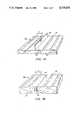
- FIGS. 1A and 1Bare simplified and fragmentary isometric views of mechanical capillary wave generators for generating traveling capillary waves having generally linear wavefronts;
- FIG. 2is a simplified and fragmentary isometric view of an ultrasonic equivalent to the capillary wave generators shown in FIGS. 1A and 1B;
- FIG. 3is a simplified and fragmentary sectional view of a more or less conventional ultrasonic generator for generating standing capillary surface waves
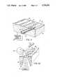
- FIG. 4is a simplified and fragmentary plan view of a capillary wave print head which is constructed in accordance with one embodiment of the present invention
- FIG. 5is a fragmentary sectional view, taken along the line 5--5 in FIG. 4, to schematically illustrate a printer comprising the print head shown in FIG. 4;
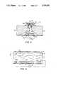
- FIG. 6is another fragmentary sectional view, taken along the line 6--6 in FIG. 4, to further illustrate the print head;
- FIG. 7is still another fragmentary sectional view, taken along the line 7--7 in FIG. 4;
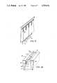
- FIG. 8is a simplified and fragmentary isometric view of an alternative embodiment of this invention.
- FIG. 9is an enlarged, fragmentary isometric view of the thermal addressing mechanism for the print head shown in FIG. 8;
- FIG. 10is a simplified and fragmentary isometric view of a print head constructed in accordance with still another embodiment of the present invention.
- FIG. 11is an enlarged, fragmentary elevational view of the interdigitated electrodes used in the addressing mechanism for the print head shown in FIG. 10;
- FIG. 12is a simplified and fragmentary isometric view of a print head having a transversely mounted discrete addressing mechanism
- FIG. 13is a simplified and fragmentary isometric view of a print head having a scanning addressing mechanism
- FIGS. 1A and 1Bthere are mechanical wave generators 21a and 21b, respectively, each of which comprises a thin plate 22 which is reciprocatingly driven (by means not shown) up and down, at a predetermined excitation frequency ⁇ e , along an axis which is essentially normal to the free surface 23 of a volume or pool of liquid 24.
- the plate 22periodically perturbs the pressure acting on the free surface 23 of the liquid 24 from above (FIG. 1A) or from below (FIG. 1B), thereby generating a substantially linear wavefront traveling capillary surface wave 25.
- the amplitude of the wave 25is gradually attenuated as it propagates away from the plate 22, so the liquid 24 suitably is confined within a reservoir (not shown) which is sufficiently large that reflected waves can be ignored.
- FIGS. 1A and 1Bdepict the wave generators 21a and 21b, respectively, just prior to the time that another crest of the capillary wave 25 is raised.
- FIG. 2there is an elongated, cylindrical, shell-like piezoelectric transducer 32 which is submerged in the pool 24.
- the transducer 32is connected across a rf or a near rf signal source 33 which is amplitude modulated (by means not shown) at the desired excitation frequency ⁇ e , so it generates a sinusoidal ultrasonic pressure wave 34.
- the contour of the transducer 32is selected to bring the pressure wave 34 to a cylindrical, line-like focus at or near the free surface 23 of the pool 24, thereby causing it to illuminate a relatively narrow strip of liquid on the surface 23.
- the radiation pressure exerted against this strip of liquidis periodically varied as a result of the amplitude modulation of the pressure wave 34, but the pressure remains below the critical "onset" amplitude for the parametric generation of a standing wave.
- the cylindrically focused pressure wave 34excites the illuminated liquid at the excitation frequency ⁇ e to generate a generally linear wavefront traveling capillary surface wave 25 which has essentially the same characteristics and behaves in essentially the same manner as its previously described mechanically generated equivalents.
- Parametric generatorsare a readily distinguishable class of devices because they vary the pressure exerted against the free surface 23 of the liquid 24 with an amplitude sufficient to generate one or more standing capillary surface waves thereon.
- the frequency, ⁇ scof these standing waves is equal to one half the excitation frequency ⁇ e .
- FIG. 3there is a generally conventional standing capillary surface wave generator 41 comprising a piezoelectric transducer 42 which is submerged in the pool 24 and connected accross a rf or near rf power supply 43, in much the same manner as the foregoing linear ultrasonic generator.
- the transducer 42is driven at a rf or near rf excitation frequency, ⁇ e , to radiate the free surface 23 of the pool 24 with an ultrasonic pressure wave 44 having an essentially constant ac amplitude at least equal to the critical "onset" or threshold level for the production of a standing capillary surface wave 45 on the surface 23.
- the amplitude of the pressure wave 44advantageously, is well above the critical threshold level for the onset of a standing wave, but still below the threshold level for the ejection of droplets.
- the capillary wave 45preferably is excited to an "incipient" energy level, just slightly below the destabilization threshold of the liquid 24, thereby reducing the amount of additional energy that is required to free droplets from the crests of the wave 45.
- the pressure wave 44may be an unconfined plane wave, such as shown, or it may be confined, such as in the embodiments discussed hereinbelow. An unconfined pressure wave 44 will more or less uniformly illuminate the free surface 23 of the liquid 24 over an area having a length and width comparable to that of the transducer 42.
- a line printer 51(shown only in relevant part) having a liquid ink print head 52 for printing an image on a suitable recording medium 53, such as a sheet or web of plain paper.
- the print head 52extends across essentially the full width of the recording medium 53 which, in turn, is advanced during operation (by means not shown) in an orthogonal or cross-line direction relative to the print head 52, as indicated by the arrow 54 (FIG. 5).
- the architecture of the printer 51imposes restrictions on the configuration and operation of its print head 52, so it is to be understood that the printer 51 is simply an example of an application in which the features of this invention may be employed to substantial advantage. It will become increasingly evident that the broader features of this invention are not limited to printing, let alone to any specific printer configuration.
- the print head 52comprises a wave generator 61 for generating a capillary surface wave 62 on the free surface 23 of a pool of liquid ink 24, together with an addressing mechanism 63 for individually addressing the crests 64 of the capillary wave 62 under the control of a controller 65.
- the wave generator 61excites the capillary wave 62 to a subthreshold amplitude level, such as an "incipient" amplitude level as previously described, so the surface 23 supports the wave 62 without being destabilized by it.
- the addressing mechanism 63selectively destabilizes one or more of the crests 64 of the wave 62 to free or eject droplets of ink (such as shown in FIG.
- the addressing mechanism 63suitably increases the amplitude of each of the selected crests 64 to a level above the destabilization threshold of the ink 24.
- the selected crests 64may be addressed serially or in parallel, although parallel addressing is preferred for line printing.
- the addressing mechanism 63has sufficient spatial resolution to address a single crest 64 of the capillary wave 62 substantially independently of its neighbors.
- the capillary wave 62is confined to a narrow, tangentially elongated channel 65 which extends across substantially the full width or transverse dimension of the recording medium 53.
- the sagittal dimension or width of the channel 65is sufficiently narrow (i.e., approximately one-half of the wavelength, ⁇ c , of the capillary wave 62) to suppress unwanted surface waves (not shown), so the wave 62 is the only surface wave of significant amplitude within the channel 65.
- the free surface 23 of the ink 24may be mechanically confined by an acoustic horn 66 having a narrow, elongated mouth 67 for defining the channel 65.
- the upper front and rear exterior shoulders 68 and 69, respectively, of the horn 66desirably come to sharp edges at its mouth 67 and are coated or otherwise treated with a hydrophobic or an oleophobic to reduce the ability of the ink 24 to wet them.
- a solid acoustic horn(not shown), could be employed to acoustically confine the capillary wave 62 to the channel 65. See the aforementioned Lovelady at al. U.S. Pat. No. 4,308,547.
- the wave generator 61For generating the capillary wave 62, the wave generator 61 comprises an elongated piezoelectric transducer 71 which is acoustically coupled to the pool of ink 24, such as by being submerged therein approximately at the base of the horn 66.
- a rf or near rf power supply 72drive the transducer 71 to cause it to produce a relatively uniform acoustic field across essentially its full width.
- the transducer 71is substantially wider than the mouth 67 of the horn 66.
- the horn 66is composed of a material having a substantially higher acoustic impedance than the ink 23 and is configured so that its forward and rearward inner sidewalls 73 and 74, respectively, are smoothly tapered inwardly toward each other for concentrating the acoustic energy supplied by the transducer 71 as it approaches the free surface 23 of the ink 24.
- the transducer 71operates without any substantial internal flexure, despite its relatively large radiating area, thereby enhancing the spatial uniformity of the acoustic field it generates.
- the transducer 71suitably comprises a two dimensional planar array of densely packed, mechanically independent, vertically poled, piezoelectric elements 75aa-75ij, such as PZT ceramic elements, which are sandwiched between and bonded to a pair of opposed, thin electrodes 76 and 77.
- the power supply 72is coupled across the electrodes 76 and 77 to excite the piezoelectric elements 75aa-75ij in unison, but the surface area of the individual elements 75aa-75ij is so small that there is no appreciable internal flexure of any of them.
- the peak-to-peak output voltage swing of the power supply 72preferably is selected so that the capillary wave 62 is a standing wave of incipient energy level.
- the notches 82are formed photolithographically. See, Bean, K. E., "Anisotropic Etching of Silicon,” IEEE Transactions on Electron Devices, Vol ED-25, No. 10, Oct. 1978, pp. 1185-1193.
- the addressing mechanism 63may be a discrete device or a scanner for freeing droplets 66 (FIG. 5) from one or more selected crests 64 of the capillary wave 62, either by reducing the surface tension of the liquid within the selected crests 64, such as by selectively heating it or spraying it with ions, or by increasing their amplitude sufficiently to destabilize them.
- the addressing mechanism 63comprises a discrete array of addressing electrodes 85, which are seated in the wave stabilizing notches 82 to align with the crests 64 of the wave 62, together with an elongated counter electrode 86, which is supported on the opposite inner sidewall of the collar 81.
- One of the advantages of providing the collar 81 for the horn 66is that entirely conventional processes may be employed to overcoat the addressing electrodes 85 and the counter electrode 86 on its forward and rearward sidewalls. As will be seen, the addressing electrodes 85 and their counter electrode 86 are relatively shallowly immersed in the ink 24.
- discrete addressing mechanismssuch as the addressing mechanism 63, permit parallel addressing of the selected crests 64 of the standing wave 62.
- the addressing electrodes 85are coupled in parallel to electrically independent outputs of the controller 65, while the counter electrode 86 is returned to a suitable reference potential, such as ground.
- the controller 65selectively applies brief bursts of moderately high voltage, high frequency pulses (e.g., bursts of 50-100 ⁇ sec.
- the frequency of these so-called secondary wavescauses them to coherently interfere with the standing wave 62, but the interference is localized because of the propagation attenuation which the secondary waves experience. Therefore, the secondary waves constructively interfere on more or less a one-for-one basis with the nearest neighboring or selected crests 64 of the wave 62, thereby destabilizing those crests to eject individual droplets 66 (FIG. 5) of ink from them.
- This addressing processmay, of course, be repeated after a short time delay during which an equilibrium state is reestablished.
- a print head 90 having an active mechanism 91 for spatially stabilizing the wave structure of the standing capillary wave 62 and/or for selectively addressing its individual crests 64is shown in FIGS. 8 and 9.
- both of those functionsare performed by an array of discrete, high speed, resistive heating elements 92 which are shallowly immersed in the ink 24 and aligned longitudinally of the capillary wave 62 on generally equidistant centers.
- the heating elements 92may be fast rise time/fast fall time resistive heaters, such as are used in so-called "bubble jet” devices, and may be supported on an inner sidewall of the print head 90.
- the center-to-center displacement of the heating elements 92is selected to be equal to one half the wavelength of the capillary wave 62 (i.e., ⁇ c /2) or an integer multiple thereof, so that the controller 93 may (1) spatially modulate the heating elements 92 at the spatial frequency of the capillary wave 62 or at a subharmonic thereof, and/or (2) selectively modulate the heating elements 92 as a function of time to cause them to individually address selected crests 64 of the capillary wave 62.
- Freely propagating capillary wavesi.e., referred to hereinabove as "secondary" waves
- the aforementioned spatial modulation of the heating elements 92periodically varies the wave propagation characteristics of the free surface 23 of the ink 24 at a suitable spatial frequency to cause the crests 64 of the capillary wave 62 to preferentially align in a fixed spatial location relative to the heating elements 92.
- the time modulation of the heating elements 92produces additional secondary capillary waves which constructively interfere with the selected crests 64 of the capillary wave 62 to free individual droplets of ink therefrom, as previously described.
- FIGS. 10 and 11there is a print head 95 having a plurality of interdigitated discrete addressing electrodes 96 and ground plane electrodes 97 which are deposited on or otherwise bonded to an inner sidewall 97 of an acoustic horn 98.
- the print head 97utilizes the operating principles of the addressing mechanism 63 shown in FIGS. 4-7 to address selected crests 64 of the wave 62, but its individual addressing electrodes 96 also are spatially modulated to spatially stabilize the structure of the capillary wave 62 with respect to the addressing electrodes 96 as previously described with reference to FIGS. 8 and 9.
- FIG. 12Another possible alternative is shown in FIG. 12 where discrete electrical or thermal addressing elements 101 for a print head 102 are supported on a suitable substrate, such as a Mylar film 103, in a transverse orientation just slightly below the free surface 23 of the ink 24.
- a suitable substratesuch as a Mylar film 103
- FIG. 13Still another alternative is shown in FIG. 13 where there is a laser 105 for supplying a suitably high power modulated light beam, together with a rotating polygon 106 for cyclically scanning the modulated laser beam lengthwise of the capillary wave 62, whereby the laser beam serially addresses selected crests 64 of the wave 62 by heating them.
- the present inventionprovides methods and means for spatially addressing capillary surface waves.
- the inventionhas important applications to liquid ink printing, but it will be evident that it is not limited thereto.
Landscapes
- Physics & Mathematics (AREA)
- Engineering & Computer Science (AREA)
- Acoustics & Sound (AREA)
- Multimedia (AREA)
- Particle Formation And Scattering Control In Inkjet Printers (AREA)
- Ink Jet (AREA)
Abstract
Description
Claims (12)
Priority Applications (6)
| Application Number | Priority Date | Filing Date | Title |
|---|---|---|---|
| US06/853,252US4719476A (en) | 1986-04-17 | 1986-04-17 | Spatially addressing capillary wave droplet ejectors and the like |
| JP62086707AJPS62251154A (en) | 1986-04-17 | 1987-04-08 | Capillary wave addressing device |
| CA000534270ACA1282281C (en) | 1986-04-17 | 1987-04-09 | Spatially addressable capillary wave droplet ejectors and the like |
| BR8701818ABR8701818A (en) | 1986-04-17 | 1987-04-15 | COMBINATION OF MEANS TO GENERATE A CAPILLARY WAVE ON A SURFACE FREE OF A VOLUME OF LIQUID |
| EP87303412AEP0243117B1 (en) | 1986-04-17 | 1987-04-16 | Spatially addressable capillary wave droplet ejectors |
| DE8787303412TDE3782761T2 (en) | 1986-04-17 | 1987-04-16 | DROP EJECTOR WORKING WITH CAPILLARY SHAFT AND SPACIOUSLY ADDRESSABLE. |
Applications Claiming Priority (1)
| Application Number | Priority Date | Filing Date | Title |
|---|---|---|---|
| US06/853,252US4719476A (en) | 1986-04-17 | 1986-04-17 | Spatially addressing capillary wave droplet ejectors and the like |
Publications (1)
| Publication Number | Publication Date |
|---|---|
| US4719476Atrue US4719476A (en) | 1988-01-12 |
Family
ID=25315505
Family Applications (1)
| Application Number | Title | Priority Date | Filing Date |
|---|---|---|---|
| US06/853,252Expired - LifetimeUS4719476A (en) | 1986-04-17 | 1986-04-17 | Spatially addressing capillary wave droplet ejectors and the like |
Country Status (6)
| Country | Link |
|---|---|
| US (1) | US4719476A (en) |
| EP (1) | EP0243117B1 (en) |
| JP (1) | JPS62251154A (en) |
| BR (1) | BR8701818A (en) |
| CA (1) | CA1282281C (en) |
| DE (1) | DE3782761T2 (en) |
Cited By (35)
| Publication number | Priority date | Publication date | Assignee | Title |
|---|---|---|---|---|
| US4959674A (en)* | 1989-10-03 | 1990-09-25 | Xerox Corporation | Acoustic ink printhead having reflection coating for improved ink drop ejection control |
| US5028937A (en)* | 1989-05-30 | 1991-07-02 | Xerox Corporation | Perforated membranes for liquid contronlin acoustic ink printing |
| US5142307A (en)* | 1990-12-26 | 1992-08-25 | Xerox Corporation | Variable orifice capillary wave printer |
| US5191354A (en)* | 1992-02-19 | 1993-03-02 | Xerox Corporation | Method and apparatus for suppressing capillary waves in an ink jet printer |
| US5194880A (en)* | 1990-12-21 | 1993-03-16 | Xerox Corporation | Multi-electrode, focused capillary wave energy generator |
| US5229793A (en)* | 1990-12-26 | 1993-07-20 | Xerox Corporation | Liquid surface control with an applied pressure signal in acoustic ink printing |
| US5339101A (en)* | 1991-12-30 | 1994-08-16 | Xerox Corporation | Acoustic ink printhead |
| US5541627A (en)* | 1991-12-17 | 1996-07-30 | Xerox Corporation | Method and apparatus for ejecting a droplet using an electric field |
| US5565113A (en)* | 1994-05-18 | 1996-10-15 | Xerox Corporation | Lithographically defined ejection units |
| US5591490A (en)* | 1994-05-18 | 1997-01-07 | Xerox Corporation | Acoustic deposition of material layers |
| US5631678A (en)* | 1994-12-05 | 1997-05-20 | Xerox Corporation | Acoustic printheads with optical alignment |
| US5666977A (en)* | 1993-06-10 | 1997-09-16 | Philip Morris Incorporated | Electrical smoking article using liquid tobacco flavor medium delivery system |
| US5821958A (en)* | 1995-11-13 | 1998-10-13 | Xerox Corporation | Acoustic ink printhead with variable size droplet ejection openings |
| US6309047B1 (en) | 1999-11-23 | 2001-10-30 | Xerox Corporation | Exceeding the surface settling limit in acoustic ink printing |
| US6318852B1 (en) | 1998-12-30 | 2001-11-20 | Xerox Corporation | Color gamut extension of an ink composition |
| US20020037359A1 (en)* | 2000-09-25 | 2002-03-28 | Mutz Mitchell W. | Focused acoustic energy in the preparation of peptide arrays |
| US6364454B1 (en) | 1998-09-30 | 2002-04-02 | Xerox Corporation | Acoustic ink printing method and system for improving uniformity by manipulating nonlinear characteristics in the system |
| US20020042077A1 (en)* | 2000-09-25 | 2002-04-11 | Ellson Richard N. | Arrays of partially nonhybridizing oligonucleotides and preparation thereof using focused acoustic energy |
| US20030012892A1 (en)* | 2001-03-30 | 2003-01-16 | Lee David Soong-Hua | Precipitation of solid particles from droplets formed using focused acoustic energy |
| US20030052943A1 (en)* | 2000-09-25 | 2003-03-20 | Ellson Richard N. | Acoustic ejection of fluids from a plurality of reservoirs |
| US6548308B2 (en) | 2000-09-25 | 2003-04-15 | Picoliter Inc. | Focused acoustic energy method and device for generating droplets of immiscible fluids |
| US20030085952A1 (en)* | 2001-11-05 | 2003-05-08 | Williams Roger O | Apparatus and method for controlling the free surface of liquid in a well plate |
| US20030133842A1 (en)* | 2000-12-12 | 2003-07-17 | Williams Roger O. | Acoustically mediated fluid transfer methods and uses thereof |
| US20030138852A1 (en)* | 2000-09-25 | 2003-07-24 | Ellson Richard N. | High density molecular arrays on porous surfaces |
| US6612686B2 (en) | 2000-09-25 | 2003-09-02 | Picoliter Inc. | Focused acoustic energy in the preparation and screening of combinatorial libraries |
| US6642061B2 (en) | 2000-09-25 | 2003-11-04 | Picoliter Inc. | Use of immiscible fluids in droplet ejection through application of focused acoustic energy |
| US20040112980A1 (en)* | 2002-12-19 | 2004-06-17 | Reichel Charles A. | Acoustically mediated liquid transfer method for generating chemical libraries |
| US6808934B2 (en) | 2000-09-25 | 2004-10-26 | Picoliter Inc. | High-throughput biomolecular crystallization and biomolecular crystal screening |
| US20050126480A1 (en)* | 2001-11-05 | 2005-06-16 | Yutaka Yamagata | Immobilizing device |
| US6925856B1 (en) | 2001-11-07 | 2005-08-09 | Edc Biosystems, Inc. | Non-contact techniques for measuring viscosity and surface tension information of a liquid |
| US7083117B2 (en) | 2001-10-29 | 2006-08-01 | Edc Biosystems, Inc. | Apparatus and method for droplet steering |
| US20070046731A1 (en)* | 2005-08-31 | 2007-03-01 | Fuji Photo Film Co., Ltd. | Liquid ejection apparatus and ejection control method |
| US7275807B2 (en) | 2002-11-27 | 2007-10-02 | Edc Biosystems, Inc. | Wave guide with isolated coupling interface |
| US20080028868A1 (en)* | 2003-12-29 | 2008-02-07 | Uwe Konzelmann | Ultrasonic Flow Sensor Having Interlaid Transmitting And Receiving Elements |
| US20100149263A1 (en)* | 2008-12-16 | 2010-06-17 | Palo Alto Research Center Incorporated | System and method for acoustic ejection of drops from a thin layer of fluid |
Families Citing this family (4)
| Publication number | Priority date | Publication date | Assignee | Title |
|---|---|---|---|---|
| JPH02269058A (en)* | 1989-03-14 | 1990-11-02 | Seiko Epson Corp | Droplet jet device using Rayleigh mode surface acoustic waves |
| GB8912245D0 (en)* | 1989-05-26 | 1989-07-12 | Pa Consulting Services | Liquid jet recording process |
| US5629724A (en)* | 1992-05-29 | 1997-05-13 | Xerox Corporation | Stabilization of the free surface of a liquid |
| JPH0880608A (en)* | 1994-09-09 | 1996-03-26 | Sony Corp | Method and device for recording |
Citations (3)
| Publication number | Priority date | Publication date | Assignee | Title |
|---|---|---|---|---|
| US3211088A (en)* | 1962-05-04 | 1965-10-12 | Sperry Rand Corp | Exponential horn printer |
| US4275290A (en)* | 1978-05-08 | 1981-06-23 | Northern Telecom Limited | Thermally activated liquid ink printing |
| US4308547A (en)* | 1978-04-13 | 1981-12-29 | Recognition Equipment Incorporated | Liquid drop emitter |
Family Cites Families (2)
| Publication number | Priority date | Publication date | Assignee | Title |
|---|---|---|---|---|
| DE3211345A1 (en)* | 1982-03-27 | 1983-09-29 | Agfa-Gevaert Ag, 5090 Leverkusen | Colour recording method and device for carrying out the method |
| JPS6164456A (en)* | 1984-09-07 | 1986-04-02 | Fuji Xerox Co Ltd | Formation of image |
- 1986
- 1986-04-17USUS06/853,252patent/US4719476A/ennot_activeExpired - Lifetime
- 1987
- 1987-04-08JPJP62086707Apatent/JPS62251154A/enactivePending
- 1987-04-09CACA000534270Apatent/CA1282281C/ennot_activeExpired - Fee Related
- 1987-04-15BRBR8701818Apatent/BR8701818A/ennot_activeIP Right Cessation
- 1987-04-16EPEP87303412Apatent/EP0243117B1/ennot_activeExpired - Lifetime
- 1987-04-16DEDE8787303412Tpatent/DE3782761T2/ennot_activeExpired - Fee Related
Patent Citations (3)
| Publication number | Priority date | Publication date | Assignee | Title |
|---|---|---|---|---|
| US3211088A (en)* | 1962-05-04 | 1965-10-12 | Sperry Rand Corp | Exponential horn printer |
| US4308547A (en)* | 1978-04-13 | 1981-12-29 | Recognition Equipment Incorporated | Liquid drop emitter |
| US4275290A (en)* | 1978-05-08 | 1981-06-23 | Northern Telecom Limited | Thermally activated liquid ink printing |
Non-Patent Citations (8)
| Title |
|---|
| Boucher, et al., "The Fundamentals of the Ultrasonic Alomization of Medicated Solutions," Annals of Allergy, Nov. 1968, vol. 26, pp. 591-600. |
| Boucher, et al., The Fundamentals of the Ultrasonic Alomization of Medicated Solutions, Annals of Allergy, Nov. 1968, vol. 26, pp. 591 600.* |
| Greanias, E. C.; Hydraulic Electrostatic Printer, IBM TDB, vol. 13, No. 5, Oct. 1970, pp. 1131 1312.* |
| Greanias, E. C.; Hydraulic-Electrostatic Printer, IBM TDB, vol. 13, No. 5, Oct. 1970, pp. 1131-1312. |
| Kenneth E. Bean, "Anisotropic Etching of Silicon," IEEE, vol. ED-25, No. 10, Oct. 1978. |
| Kenneth E. Bean, Anisotropic Etching of Silicon, IEEE, vol. ED 25, No. 10, Oct. 1978.* |
| W. Eisenmenger, "Surface Tension of Water," Acustica, 1959, vol. 9, pp. 327-340. |
| W. Eisenmenger, Surface Tension of Water, Acustica, 1959, vol. 9, pp. 327 340.* |
Cited By (64)
| Publication number | Priority date | Publication date | Assignee | Title |
|---|---|---|---|---|
| US5028937A (en)* | 1989-05-30 | 1991-07-02 | Xerox Corporation | Perforated membranes for liquid contronlin acoustic ink printing |
| US4959674A (en)* | 1989-10-03 | 1990-09-25 | Xerox Corporation | Acoustic ink printhead having reflection coating for improved ink drop ejection control |
| US5194880A (en)* | 1990-12-21 | 1993-03-16 | Xerox Corporation | Multi-electrode, focused capillary wave energy generator |
| US5142307A (en)* | 1990-12-26 | 1992-08-25 | Xerox Corporation | Variable orifice capillary wave printer |
| US5229793A (en)* | 1990-12-26 | 1993-07-20 | Xerox Corporation | Liquid surface control with an applied pressure signal in acoustic ink printing |
| US5541627A (en)* | 1991-12-17 | 1996-07-30 | Xerox Corporation | Method and apparatus for ejecting a droplet using an electric field |
| US5339101A (en)* | 1991-12-30 | 1994-08-16 | Xerox Corporation | Acoustic ink printhead |
| US5191354A (en)* | 1992-02-19 | 1993-03-02 | Xerox Corporation | Method and apparatus for suppressing capillary waves in an ink jet printer |
| US5666977A (en)* | 1993-06-10 | 1997-09-16 | Philip Morris Incorporated | Electrical smoking article using liquid tobacco flavor medium delivery system |
| US5565113A (en)* | 1994-05-18 | 1996-10-15 | Xerox Corporation | Lithographically defined ejection units |
| US5591490A (en)* | 1994-05-18 | 1997-01-07 | Xerox Corporation | Acoustic deposition of material layers |
| US5631678A (en)* | 1994-12-05 | 1997-05-20 | Xerox Corporation | Acoustic printheads with optical alignment |
| US5821958A (en)* | 1995-11-13 | 1998-10-13 | Xerox Corporation | Acoustic ink printhead with variable size droplet ejection openings |
| US6364454B1 (en) | 1998-09-30 | 2002-04-02 | Xerox Corporation | Acoustic ink printing method and system for improving uniformity by manipulating nonlinear characteristics in the system |
| US6318852B1 (en) | 1998-12-30 | 2001-11-20 | Xerox Corporation | Color gamut extension of an ink composition |
| US6309047B1 (en) | 1999-11-23 | 2001-10-30 | Xerox Corporation | Exceeding the surface settling limit in acoustic ink printing |
| US6666541B2 (en) | 2000-09-25 | 2003-12-23 | Picoliter Inc. | Acoustic ejection of fluids from a plurality of reservoirs |
| US20070015213A1 (en)* | 2000-09-25 | 2007-01-18 | Picoliter Inc. | Peptide arrays and methods of preparation |
| US7901039B2 (en) | 2000-09-25 | 2011-03-08 | Picoliter Inc. | Peptide arrays and methods of preparation |
| US20030052943A1 (en)* | 2000-09-25 | 2003-03-20 | Ellson Richard N. | Acoustic ejection of fluids from a plurality of reservoirs |
| US20030059522A1 (en)* | 2000-09-25 | 2003-03-27 | Mutz Mitchell W. | Focused acoustic energy in the preparation of peptide arrays |
| US6548308B2 (en) | 2000-09-25 | 2003-04-15 | Picoliter Inc. | Focused acoustic energy method and device for generating droplets of immiscible fluids |
| US20020042077A1 (en)* | 2000-09-25 | 2002-04-11 | Ellson Richard N. | Arrays of partially nonhybridizing oligonucleotides and preparation thereof using focused acoustic energy |
| US7090333B2 (en) | 2000-09-25 | 2006-08-15 | Picoliter Inc. | Focused acoustic energy in the preparation of peptide arrays |
| US6938987B2 (en) | 2000-09-25 | 2005-09-06 | Picoliter, Inc. | Acoustic ejection of fluids from a plurality of reservoirs |
| US20030138852A1 (en)* | 2000-09-25 | 2003-07-24 | Ellson Richard N. | High density molecular arrays on porous surfaces |
| US6612686B2 (en) | 2000-09-25 | 2003-09-02 | Picoliter Inc. | Focused acoustic energy in the preparation and screening of combinatorial libraries |
| US20040252163A1 (en)* | 2000-09-25 | 2004-12-16 | Ellson Richard N. | Acoustic ejection of fluids from a plurality of reservoirs |
| US6808934B2 (en) | 2000-09-25 | 2004-10-26 | Picoliter Inc. | High-throughput biomolecular crystallization and biomolecular crystal screening |
| US6806051B2 (en) | 2000-09-25 | 2004-10-19 | Picoliter Inc. | Arrays of partially nonhybridizing oligonucleotides and preparation thereof using focused acoustic energy |
| US6802593B2 (en) | 2000-09-25 | 2004-10-12 | Picoliter Inc. | Acoustic ejection of fluids from a plurality of reservoirs |
| US6642061B2 (en) | 2000-09-25 | 2003-11-04 | Picoliter Inc. | Use of immiscible fluids in droplet ejection through application of focused acoustic energy |
| US6746104B2 (en) | 2000-09-25 | 2004-06-08 | Picoliter Inc. | Method for generating molecular arrays on porous surfaces |
| US20020037359A1 (en)* | 2000-09-25 | 2002-03-28 | Mutz Mitchell W. | Focused acoustic energy in the preparation of peptide arrays |
| US20080103054A1 (en)* | 2000-12-12 | 2008-05-01 | Williams Roger O | Acoustically mediated fluid transfer methods and uses thereof |
| US6596239B2 (en) | 2000-12-12 | 2003-07-22 | Edc Biosystems, Inc. | Acoustically mediated fluid transfer methods and uses thereof |
| US8137640B2 (en) | 2000-12-12 | 2012-03-20 | Williams Roger O | Acoustically mediated fluid transfer methods and uses thereof |
| US20030203505A1 (en)* | 2000-12-12 | 2003-10-30 | Williams Roger O. | Acoustically mediated fluid transfer methods and uses thereof |
| US20030203386A1 (en)* | 2000-12-12 | 2003-10-30 | Williams Roger O. | Acoustically mediated fluid transfer methods and uses thereof |
| US20030186459A1 (en)* | 2000-12-12 | 2003-10-02 | Williams Roger O. | Acoustically mediated fluid transfer methods and uses thereof |
| US20030186460A1 (en)* | 2000-12-12 | 2003-10-02 | Williams Roger O. | Acoustically mediated fluid transfer methods and uses thereof |
| US20040009611A1 (en)* | 2000-12-12 | 2004-01-15 | Williams Roger O. | Acoustically mediated fluid transfer methods and uses thereof |
| US20030133842A1 (en)* | 2000-12-12 | 2003-07-17 | Williams Roger O. | Acoustically mediated fluid transfer methods and uses thereof |
| US20030211632A1 (en)* | 2000-12-12 | 2003-11-13 | Williams Roger O. | Acoustically mediated fluid transfer methods and uses thereof |
| US20030012892A1 (en)* | 2001-03-30 | 2003-01-16 | Lee David Soong-Hua | Precipitation of solid particles from droplets formed using focused acoustic energy |
| US6869551B2 (en) | 2001-03-30 | 2005-03-22 | Picoliter Inc. | Precipitation of solid particles from droplets formed using focused acoustic energy |
| US7083117B2 (en) | 2001-10-29 | 2006-08-01 | Edc Biosystems, Inc. | Apparatus and method for droplet steering |
| US20030085952A1 (en)* | 2001-11-05 | 2003-05-08 | Williams Roger O | Apparatus and method for controlling the free surface of liquid in a well plate |
| US20050126480A1 (en)* | 2001-11-05 | 2005-06-16 | Yutaka Yamagata | Immobilizing device |
| US7516714B2 (en)* | 2001-11-05 | 2009-04-14 | Riken | Immobilizing device |
| US6925856B1 (en) | 2001-11-07 | 2005-08-09 | Edc Biosystems, Inc. | Non-contact techniques for measuring viscosity and surface tension information of a liquid |
| US7968060B2 (en) | 2002-11-27 | 2011-06-28 | Edc Biosystems, Inc. | Wave guide with isolated coupling interface |
| US7275807B2 (en) | 2002-11-27 | 2007-10-02 | Edc Biosystems, Inc. | Wave guide with isolated coupling interface |
| US20070296760A1 (en)* | 2002-11-27 | 2007-12-27 | Michael Van Tuyl | Wave guide with isolated coupling interface |
| US20040120855A1 (en)* | 2002-12-19 | 2004-06-24 | Edc Biosystems, Inc. | Source and target management system for high throughput transfer of liquids |
| US6863362B2 (en) | 2002-12-19 | 2005-03-08 | Edc Biosystems, Inc. | Acoustically mediated liquid transfer method for generating chemical libraries |
| US7429359B2 (en) | 2002-12-19 | 2008-09-30 | Edc Biosystems, Inc. | Source and target management system for high throughput transfer of liquids |
| US20040112978A1 (en)* | 2002-12-19 | 2004-06-17 | Reichel Charles A. | Apparatus for high-throughput non-contact liquid transfer and uses thereof |
| US20040112980A1 (en)* | 2002-12-19 | 2004-06-17 | Reichel Charles A. | Acoustically mediated liquid transfer method for generating chemical libraries |
| US7500403B2 (en)* | 2003-12-29 | 2009-03-10 | Robert Bosch Gmbh | Ultrasonic flow sensor having interlaid transmitting and receiving elements |
| US20080028868A1 (en)* | 2003-12-29 | 2008-02-07 | Uwe Konzelmann | Ultrasonic Flow Sensor Having Interlaid Transmitting And Receiving Elements |
| US20070046731A1 (en)* | 2005-08-31 | 2007-03-01 | Fuji Photo Film Co., Ltd. | Liquid ejection apparatus and ejection control method |
| US20100149263A1 (en)* | 2008-12-16 | 2010-06-17 | Palo Alto Research Center Incorporated | System and method for acoustic ejection of drops from a thin layer of fluid |
| US8079676B2 (en) | 2008-12-16 | 2011-12-20 | Palo Alto Research Center Incorporated | System and method for acoustic ejection of drops from a thin layer of fluid |
Also Published As
| Publication number | Publication date |
|---|---|
| EP0243117A2 (en) | 1987-10-28 |
| DE3782761T2 (en) | 1993-05-13 |
| JPS62251154A (en) | 1987-10-31 |
| EP0243117A3 (en) | 1988-12-07 |
| CA1282281C (en) | 1991-04-02 |
| DE3782761D1 (en) | 1993-01-07 |
| BR8701818A (en) | 1988-01-26 |
| EP0243117B1 (en) | 1992-11-25 |
Similar Documents
| Publication | Publication Date | Title |
|---|---|---|
| US4719476A (en) | Spatially addressing capillary wave droplet ejectors and the like | |
| US4719480A (en) | Spatial stablization of standing capillary surface waves | |
| JP2842320B2 (en) | Droplet ejection device and droplet ejection method | |
| US6155671A (en) | Liquid ejector which uses a high-order ultrasonic wave to eject ink droplets and printing apparatus using same | |
| JP3206841B2 (en) | Method and apparatus for ejecting droplets using an electric field | |
| US4308547A (en) | Liquid drop emitter | |
| WO1990014233A1 (en) | Liquid jet recording process and apparatus therefore | |
| US5305016A (en) | Traveling wave ink jet printer with drop-on-demand droplets | |
| JPH0349958A (en) | Acoustic ink printer | |
| US5142307A (en) | Variable orifice capillary wave printer | |
| US6196664B1 (en) | Ink droplet eject apparatus and method | |
| JPH05278218A (en) | Ink jet printer | |
| US6336707B1 (en) | Recording element and recording device | |
| JP2002127403A (en) | Operating method for ink jet print head | |
| EP0216589B1 (en) | Leaky rayleigh wave nozzleless liquid droplet ejectors | |
| EP0234718B1 (en) | Droplet ejectors | |
| US5917521A (en) | Ink jet recording apparatus and method for jetting an ink droplet from a free surface of an ink material using vibrational energy | |
| JPH01237152A (en) | Liquid jet recording method | |
| JP2742077B2 (en) | Inkjet head | |
| US6511157B1 (en) | Ink jet printerhead with a plurality of nozzles and two distinct groups of filters | |
| JPH10193592A (en) | Liquid jet apparatus | |
| JPH09226111A (en) | Recording method and recorder | |
| JPH1034909A (en) | Liquid jetting device | |
| JPH1058673A (en) | Ink jet recording head | |
| JPH1034913A (en) | Ink jet recording head |
Legal Events
| Date | Code | Title | Description |
|---|---|---|---|
| AS | Assignment | Owner name:XEROX CORPORATION, STAMFORD, FAIRFIELD, CONNECTICU Free format text:ASSIGNMENT OF ASSIGNORS INTEREST.;ASSIGNORS:ELROD, SCOTT A.;KHURI-YAKUB, BUTRUS T.;QUATE, CALVIN F.;REEL/FRAME:004540/0693;SIGNING DATES FROM 19860411 TO 19860414 | |
| STCF | Information on status: patent grant | Free format text:PATENTED CASE | |
| FPAY | Fee payment | Year of fee payment:4 | |
| SULP | Surcharge for late payment | ||
| REMI | Maintenance fee reminder mailed | ||
| FPAY | Fee payment | Year of fee payment:8 | |
| FPAY | Fee payment | Year of fee payment:12 | |
| AS | Assignment | Owner name:BANK ONE, NA, AS ADMINISTRATIVE AGENT, ILLINOIS Free format text:SECURITY INTEREST;ASSIGNOR:XEROX CORPORATION;REEL/FRAME:013153/0001 Effective date:20020621 | |
| AS | Assignment | Owner name:JPMORGAN CHASE BANK, AS COLLATERAL AGENT, TEXAS Free format text:SECURITY AGREEMENT;ASSIGNOR:XEROX CORPORATION;REEL/FRAME:015134/0476 Effective date:20030625 Owner name:JPMORGAN CHASE BANK, AS COLLATERAL AGENT,TEXAS Free format text:SECURITY AGREEMENT;ASSIGNOR:XEROX CORPORATION;REEL/FRAME:015134/0476 Effective date:20030625 | |
| AS | Assignment | Owner name:XEROX CORPORATION, CONNECTICUT Free format text:RELEASE BY SECURED PARTY;ASSIGNOR:JPMORGAN CHASE BANK, N.A. AS SUCCESSOR-IN-INTEREST ADMINISTRATIVE AGENT AND COLLATERAL AGENT TO JPMORGAN CHASE BANK;REEL/FRAME:066728/0193 Effective date:20220822 |