US4719460A - Keyless entry system for automotive vehicle devices with theft-prevention feature - Google Patents
Keyless entry system for automotive vehicle devices with theft-prevention featureDownload PDFInfo
- Publication number
- US4719460A US4719460AUS06/651,782US65178284AUS4719460AUS 4719460 AUS4719460 AUS 4719460AUS 65178284 AUS65178284 AUS 65178284AUS 4719460 AUS4719460 AUS 4719460A
- Authority
- US
- United States
- Prior art keywords
- lock device
- transmitter
- keyless entry
- entry system
- radio signal
- Prior art date
- Legal status (The legal status is an assumption and is not a legal conclusion. Google has not performed a legal analysis and makes no representation as to the accuracy of the status listed.)
- Expired - Lifetime
Links
- 230000004044responseEffects0.000claimsdescription12
- 230000005540biological transmissionEffects0.000claimsdescription5
- 230000005674electromagnetic inductionEffects0.000claimsdescription5
- 230000000994depressogenic effectEffects0.000description7
- 238000010586diagramMethods0.000description5
- 230000004048modificationEffects0.000description5
- 238000012986modificationMethods0.000description5
- 206010007134Candida infectionsDiseases0.000description1
- 230000003213activating effectEffects0.000description1
- 230000004913activationEffects0.000description1
- QSHDDOUJBYECFT-UHFFFAOYSA-NmercuryChemical compound[Hg]QSHDDOUJBYECFT-UHFFFAOYSA-N0.000description1
- 229910052753mercuryInorganic materials0.000description1
- 230000002035prolonged effectEffects0.000description1
- 239000007858starting materialSubstances0.000description1
Images


Classifications
- B—PERFORMING OPERATIONS; TRANSPORTING
- B60—VEHICLES IN GENERAL
- B60R—VEHICLES, VEHICLE FITTINGS, OR VEHICLE PARTS, NOT OTHERWISE PROVIDED FOR
- B60R25/00—Fittings or systems for preventing or indicating unauthorised use or theft of vehicles
- B60R25/20—Means to switch the anti-theft system on or off
- B60R25/24—Means to switch the anti-theft system on or off using electronic identifiers containing a code not memorised by the user
- G—PHYSICS
- G07—CHECKING-DEVICES
- G07C—TIME OR ATTENDANCE REGISTERS; REGISTERING OR INDICATING THE WORKING OF MACHINES; GENERATING RANDOM NUMBERS; VOTING OR LOTTERY APPARATUS; ARRANGEMENTS, SYSTEMS OR APPARATUS FOR CHECKING NOT PROVIDED FOR ELSEWHERE
- G07C9/00—Individual registration on entry or exit
- G07C9/00174—Electronically operated locks; Circuits therefor; Nonmechanical keys therefor, e.g. passive or active electrical keys or other data carriers without mechanical keys
- G07C9/00309—Electronically operated locks; Circuits therefor; Nonmechanical keys therefor, e.g. passive or active electrical keys or other data carriers without mechanical keys operated with bidirectional data transmission between data carrier and locks
- G07C2009/00388—Electronically operated locks; Circuits therefor; Nonmechanical keys therefor, e.g. passive or active electrical keys or other data carriers without mechanical keys operated with bidirectional data transmission between data carrier and locks code verification carried out according to the challenge/response method
- G07C2009/00404—Electronically operated locks; Circuits therefor; Nonmechanical keys therefor, e.g. passive or active electrical keys or other data carriers without mechanical keys operated with bidirectional data transmission between data carrier and locks code verification carried out according to the challenge/response method starting with prompting the lock
- G—PHYSICS
- G07—CHECKING-DEVICES
- G07C—TIME OR ATTENDANCE REGISTERS; REGISTERING OR INDICATING THE WORKING OF MACHINES; GENERATING RANDOM NUMBERS; VOTING OR LOTTERY APPARATUS; ARRANGEMENTS, SYSTEMS OR APPARATUS FOR CHECKING NOT PROVIDED FOR ELSEWHERE
- G07C9/00—Individual registration on entry or exit
- G07C9/00174—Electronically operated locks; Circuits therefor; Nonmechanical keys therefor, e.g. passive or active electrical keys or other data carriers without mechanical keys
- G07C2009/00753—Electronically operated locks; Circuits therefor; Nonmechanical keys therefor, e.g. passive or active electrical keys or other data carriers without mechanical keys operated by active electrical keys
- G07C2009/00769—Electronically operated locks; Circuits therefor; Nonmechanical keys therefor, e.g. passive or active electrical keys or other data carriers without mechanical keys operated by active electrical keys with data transmission performed by wireless means
- G07C2009/00793—Electronically operated locks; Circuits therefor; Nonmechanical keys therefor, e.g. passive or active electrical keys or other data carriers without mechanical keys operated by active electrical keys with data transmission performed by wireless means by Hertzian waves
- Y—GENERAL TAGGING OF NEW TECHNOLOGICAL DEVELOPMENTS; GENERAL TAGGING OF CROSS-SECTIONAL TECHNOLOGIES SPANNING OVER SEVERAL SECTIONS OF THE IPC; TECHNICAL SUBJECTS COVERED BY FORMER USPC CROSS-REFERENCE ART COLLECTIONS [XRACs] AND DIGESTS
- Y10—TECHNICAL SUBJECTS COVERED BY FORMER USPC
- Y10T—TECHNICAL SUBJECTS COVERED BY FORMER US CLASSIFICATION
- Y10T70/00—Locks
- Y10T70/50—Special application
- Y10T70/5889—For automotive vehicles
- Y10T70/5956—Steering mechanism with switch
- Y—GENERAL TAGGING OF NEW TECHNOLOGICAL DEVELOPMENTS; GENERAL TAGGING OF CROSS-SECTIONAL TECHNOLOGIES SPANNING OVER SEVERAL SECTIONS OF THE IPC; TECHNICAL SUBJECTS COVERED BY FORMER USPC CROSS-REFERENCE ART COLLECTIONS [XRACs] AND DIGESTS
- Y10—TECHNICAL SUBJECTS COVERED BY FORMER USPC
- Y10T—TECHNICAL SUBJECTS COVERED BY FORMER US CLASSIFICATION
- Y10T70/00—Locks
- Y10T70/50—Special application
- Y10T70/5889—For automotive vehicles
- Y10T70/5973—Remote control
Definitions
- the present inventionrelates generally to a keyless entry system for operating automotive vehicle devices, such as door lock device, trunk lid opener, glove box key, steering lock device, without mechanical keys. More particularly, the invention relates to a theft-preventive keyless entry system which prevents operation of automotive vehicle devices under preselected conditions.
- a keyboardis provided on the external surface of the vehicle body to allow entry of a predetermined code authorizing access to one or more desired vehicle devices.
- the designated vehicle devicesare electrically operated when the entered code matches a predetermined code.
- the present inventionprovides a novel and more useful system for operating the vehicle devices without an ignition key and without requiring manual entry of a predetermined code.
- Another object of the present inventionis to provide a theft-proof keyless entry system which prevents operation of the specified vehicle devices under predetermined conditions.
- a keyless entry system for automotive vehicle devicescomprises a wireless code transmitter which is portable by hand or in pockets, and a controller connected to vehicle devices to electrically operate the latter in response to a preset code transmitted from the transmitter.
- the transmittertransmits a code signal to the controller when one of the vehicle devices is to be operated.
- the controlleris responsive to the code signal, when the transmitted code matches a preset code, produces a driver signal which actuates the designated vehicle device.
- a switch which activates a transmitteris provided on the external surface of the vehicle body and connected to the controller.
- the controllertransmits a demand signal to the transmitter possessed by the user.
- the transmitterresponds to the demand signal by transmitting the code signal to the controller.
- a theft-proof systemis incorporated in the controller, which disconnects the controller from the vehicle devices under predetermined conditions.
- a keyless entry system for an automotive vehicle devicescomprises an electrical actuator associated with the lock device and responsive a control signal to reverse the position of the lock device, a manual switch manually operable to activate the actuator, a transmitter responsive to operation of the manual switch to output a radio signal indicative of a unique code which identifies the transmitter, a controller for receiving the radio signal from the transmitter, comparing the unique code indicated by the radio signal with a preset code, and producing the control signal when the unique code matches the preset code.
- a disabling meansis connected to the controller for detecting a predetermined disabling condition and disabling the controller when the predetermined disabling condition is detected.
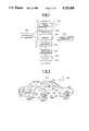
- FIG. 1is a schematic block diagram showing the general concepts of a keyless entry system for an automotive vehicle device according to the present invention
- FIG. 2is a perspective view of an automotive vehicle to which the keyless entry system according to the present invention is applied;
- FIG. 3is a block diagram of a transmitter in the first embodiment of a keyless entry system according to the present invention.
- FIG. 4is a block diagram of a controller in the first embodiment of the keyless entry system according to the present invention.
- FIGS. 5(A) and 5(B)are flowcharts of the operation of the transmitter and the receiver, respectively;
- FIG. 6is a perspective view of a modification of an ignition switch arrangement
- FIG. 7is a block diagram of a modification of the first embodiment of the keyless entry system of FIG. 4;
- FIG. 8is a flowchart of a modified second control program to be executed by the controller of FIG. 7;
- FIG. 9is a block diagram of the second embodiment of a controller.
- the first embodiment of a keyless entry system for an automotive vehiclegenerally comprises a code transmitter 100 and a controller 200.
- the controller 200is connected via a driver signal generator 204 to actuators 202 for vehicle devices such as door lock device, a trunk lid lock device, a groove box lid locks and a steering lock device.
- the controller 200is also connected to a disable signal generator 300 which can produce a disable signal to selectably disable the controller.
- the disable signal generator 300responds to predetermined conditions by producing the disable signal.
- the disable signal generator 300detects when an ignition switch 302 is in a position other than the OFF position. For instance, the disable signal generator 300 outputs the disable signal when the ignition switch 302 is in the ACC position, wherein electric power is supplied to electrical accessories in the vehicle, or the IGN position, wherein electric power is supplied to an engine ignition system and to the electrical accessories, or the START position wherein electric power is applied to a starter motor (not shown).
- the controller 200includes a demand signal generator 208 which sends a demand signal SD to the transmitter 100 to activate the latter.
- the demand signal generator 208is connected to one or more manual switches 210 which are placed on the external surface of the vehicle so as to be accessible from outside the vehicle.
- the demand signal generator 208produces a demand signal SD when one of the manual switches 210 is depressed.
- the transmitter 100includes a receiver circuit 102 for receiving the demand signal SD from the controller.
- the transmitter 100becomes active when the receiving circuit 102 receives the demand signal SD to produce a code signal SC which is indicative of a preset specific code.
- the preset code of the portable transmitter 100differs from that of the demand signal generator 208 so that the controller 200 can recognize when the transmitter 100 is responding.
- the transmitter 100continuously transmits the code signal SC to the controller for as long as it remains active.
- the code signal SCis received by a receiver 212 in the controller 200.
- the controller 200has a comparator 213 to compare the received code with a specific preset code. When the received code matches the code preset as compared in the comparator 213 the controller 200 sends a control signal SL to the driver circuit generator 204.
- the driver signal generator 204in turn sends a drive signal to one of the actuators 202 corresponding to the manual switch 210 operated.
- the actuator 202in activated by the driver signal from the driver signal generator 204 to operate the corresponding vehicle device.
- the actuators 202actuate the vehicle devices from the current position to the opposite position in response to the driver signal. For instance, when the vehicle device is in the locked position, the actuator unlocks the vehicle device in response to the driver signal. On the other hand, when the driver signal is sent to the actuator of a vehicle device which currently unlocked, that vehicle device is then locked.
- the transmitter 100includes a transmitter/receiver antenna 104.
- a loop antenna 214is built into one of the windows 216 of the vehicle.
- the loop antenna 214transmits the demand signal SD to and receives the code signal SC from the transmitter 100.
- the manual switches 210are mounted on an escutcheon 218 of an outside door handle for operation from outside the vehicle.
- the transmitter 100is housed in a case small enough to hand-carry or to pocket.
- FIG. 3shows the circuit structure of the transmitter 100.
- a microprocessor 106is connected to the antenna 104 via a demodulator 108 which demodulates the received demand signal SD.
- the microprocessor 106includes a memory 110 storing the preset code.
- the microprocessor 106reads out the preset code to a modulator 112.
- the modulator 112is, in turn, connected to a carrier-wave generator 114 to receive a carrier wave.
- the modulator 112modulates the carrier-wave with the code-indicative signal from the microprocessor 106 to produce the final code signal SC.
- the antenna 104 of the transmitter 100is built into the transmitter circuit board or on the surface of the transmitter casing 116 (shown in FIG. 2).
- the casing 116is the size of a name card and thin enough to carry in a shirt pocket.
- the transmitter 100uses a long-life, compact battery, such as a mercury battery, as a power source.
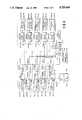
- FIG. 4shows the circuitry of the controller 200.
- the shown embodiment of the keyless entry systemis adapted to operate the door locks, the trunk lid lock, the glove box lock and the steering lock device.
- the shown embodimentis adapted to control operation of the locks for the right- and left-side doors independently.
- manual switches 210-DR, 210-DL, 210-TL, 210-GL and 210-STare provided on the vehicle body somewhere nearby the devices to be operated.
- the manual switches 210-DR and 210-DLare provided adjacent the door handles of respectively corresponding side soors.
- the manual switch 210-TL to operate the trunk lid lock devicewould be placed adjacent the trunk lid.
- Each manual switchis operable independently to operate the corresponding lock device. For example, when the manual switch 210-DR is depressed, the right-side door lock 220-DR is actuated to either to the locked or unlocked state.
- Each manual switch 210-DR, 210-DL, 210-TL, 210-GL and 210-STis connected to a timer 222-DR, 222-DL, 222-TL, 222-GL and 222-ST through a normally closed relay 224-DR, 224-DL, 224-TL, 224-GL and 224-ST.
- the timerswhich will be referred to generically with reference numeral "222”, are responsive to depression of the corresponding manual switch, which will be referred to generically with reference numeral "210”, to produce a HIGH-level timer signal St for a given period of time.
- the timer signal Stis fed to a corresponding AND-gate 226-DR, 226-DL, 226-TL, 226-GL and 226-ST, which will be referred to generically with reference numeral "226".
- the timer signal Stis fed to a corresponding switching circuit 228-DR, 228-DL, 228-TL, 228-GL and 228-ST, which will be referred to generically with reference numeral "228".
- the switching circuit 228closes in response to the timer signal St to connect the corresponding antenna 214-DR, 214-DL, 214-TL, 214-GL or 214-ST, which will be referred to generically with reference numeral "214", to a demodulator 230, whereby the code signal SC received by the corresponding antenna 214 is conducted to the demodulator.
- the timers 222are also all connected to a microprocessor 232 via a multi-input OR gate 234.
- the microprocessor 232includes a memory 236 which stores the preset code corresponding to that stored in the transmitter 100.
- the antennas 214-DR, 214-DL, 214-TL, 214-GL or 214-STare located adjacent respectively corresponding vehicle devices to be operated.
- the antennas 214-DR and 214-DLare mounted on respectively corresponding side windshields
- the antenna 214-TL for operating the trunk lid lock devicemay be provided on the rear windshield or the edge of rear windshield opening
- antennas 214-ST and 214-GL for steering lock device and the glove box lid lock devicemay be mounted on the front windshield or along the edge of the front windshield opening.
- the microprocessor 232responds to the timer signal St received via the OR gate 234 by outputting the demand signal SD to the transmitter through a modulator 238 and antenna 214.
- the modulator 238is connected to the antenna 214 via the switching circuits 228 to transmit the demand signal SD to the transmitter 100.
- the microprocessor 232receives the code signal SC via the antenna 214 and the demodulator 230 and compares the received code with the stored code. When the received code matches the stored code, the microprocessor 232 outputs the control signal SL to the other input terminal of the AND gate 226 corresponding to the depressed manual switch.
- AND gate 226transmits a HIGH-level signal to the driver signal generator 204-DR, 204-DL, 204-TL, 204-GL or 204-ST, which will be referred to generically with reference numeral "204".
- the driver signal generator 204responds to the HIGH-level signal by outputting a driver signal to the corresponding actuator 202-DR, 202-DL, 202-TL, 202-GL or 202-ST of the lock 220-DR, 220-DL, 220-TL, 220-GL or 220-ST.
- the ignition switch 302serves as the disabling signal generator 300 and is connected to each of the relay coils 240-DR, 240-DL, 240-TL, 240-GL and 240-ST of the relays 224-DR, 224-DL, 224-TL, 224-GL and 224-ST.
- the relay coil 240is energized to open the relay 224.
- electrical communication between the manual switch 210 and the timer 222is broken. Therefore, as long as the ignition switch 302 remains in either the IGN or ACC position, the keyless entry system is disabled.
- the relay coil 240is held deenergized, allowing the relay to close. Therefore as long as the ignition switch remains OFF, the keyless entry system remains active.
- the microprocessor 106 of the transmitter 100repeatedly executes the first control program illustrated in FIG. 5(A).
- the microprocessor 106checks for receipt of the demand signal SD from the controller at a step 1002.
- the step 1002is repeated until the demand signal SD is received.
- the transmitter 100normally remains in a stand-by state, waiting to produce the code signal SC in response to the demand signal SD.
- the preset codeis read from the memory 110 at a step 1004.
- the microprocessor 106then outputs the code-indicative signal to the modulator 112 which in turn outputs the code signal SC in step 1006. Control then returns to the stand-by step 1002.
- the code signal SCis transmitted from the modulator to the controller for a given period of time and terminates when the given period of time expires.
- the given period of time during which the code signal SC is tranmittedis so chosen that the controller 200 can activate the actuator 202 designated by the operated manual switch before expiration of that period.
- the code stored in the memory 110is preferably a binary code, such as an 8-bit serial datum. This binary code rides on the carrier wave as modulated by the modulator to form the code signal SC.
- FIG. 5(B)is a flowchart for the controller.
- the microprocessor 232checks for receipt of the timer signal St at a step 2002. If the timer signal St is not detected when checked at the step 2002, the second program ends. This is substantially the same as the loop at the step 1002 in FIG. 5(A) and holds the controller in stand-by until depression of a manual switch.
- controlpasses to a step 2004, in which the modulator 238 is activated to send a demand signal SD to the transmitter 100 to activate the latter.
- the controller 200enters a second stand-by state, waiting for the code signal SC. Specifically, a step 2006 is repeated as a loop until the code signal SC is received. After the code signal SC is input via the antenna 214 and the demodulator 230, the received code in the code signal SC is read out at a step 2008. The preset code of the controller 200 is then read out from the memory 236, at a step 2010. The input code and the preset code read out in steps 2008 and 2010 are compared at a step 2012. If the codes match, a matching flag FM is set at the step 2012. The matching flag FM is checked at a step 2014. If the matching flag FM is not set, the program ends. On the other hand, if the matching flag FM is set when checked at the step 2014, then the control signal SL is sent to the driver signal generator at a step 2016.
- the code signal SCis output only when the demand signal SD is input from the controller, consumption of electric power of the battery in the transmitter is significantly reduced in comparison with system which might employ constant transmission of the code signal SC.
- the life-time of the battery of the transmitteris prolonged even though electric power is constantly supplied to the microprocessor to hold same in stand-by. It should be appreciated that the electric power needed to power the microprocessor is substantially smaller than that consumed in transmitting the code signal SC. Therefore, constant power supply to the microprocessor will not significantly affect the life-time of the battery.
- transmission of the demand signal SD and the code signal SCis performed by electromagnetic induction. Since locking and unlocking operations of the lock devices will generally be performed only when the transmitter is near the controller, good communication between the transmitter and the controller can be obtained by electromagnetic induction without significant power consumption.
- the manual switch 210-DRis depressed.
- the timer 222-DRbecomes active to output the timer signal St.
- the timer signal Stis applied to the AND gate 226-DR and to the switching circuit 228-DR, the latter of which then closes to connect the antenna 214-DR to the microprocessor 232.
- the timer signal St from the timer 222-DRis also input to the microprocessor 232 via the OR gate 234.
- the microprocessor 232responds inputs from the OR gate 234 by activating the modulator 238 to transmit the demand signal SD via the antenna 214-DR.
- the demand signal SD transmitted via the antenna 214-DRis received by the antenna 104 of the transmitter 100. Then, the demand signal SD is demodulated by the demodulator 108 to remove the carrier-wave components.
- the microprocessor 106 of the transmitter 100then executes the steps 1004 and 1006 of the first control program of FIG. 5(A) and outputs the code-indicative signal to the modulator 112.
- the modulator 112thus transmits the code signal SC to the controller 200 via the antenna 104.
- the code signal SCis received by the antenna 214-DR and fed to the demodulator 230.
- the demodulator 230demodulates the code signal SC to remove the carrier-wave components.
- the microprocessor 232receives the demodulated code signal SC and executes the steps 2008 to 2016 of the second control program.
- the microprocessor 232feeds the control signal SL to the AND gate 226-DR.
- the AND gatepasses a HIGH-level signal to the driver signal generator 204-DR which produces the driver signal.
- the driver signalis applied to the actuator 202-DR of the right-side door lock device 220-DR to reverse the lock position. Since the right-side door lock device 220-DR was originally locked, it becomes unlocked upon activation of the actuator 202-DR.
- the antenna 214-DLsends the code signal SC to the microprocessor. If the input code matches the preset code, the AND gate 226-DL opens to activate the driver signal generator 204-DL. Thus, if the left-side door lock device is originally unlocked, it becomes locked.
- the timer 222-TLWhen the manual switch 210-TL is operated, the timer 222-TL become active to send a timer signal St to the AND gate 226-TL and the switching circuit 228-TL.
- the switching circuit 228-TLthen closes to establish electrical communication between the antenna 214-TL and the demodulator 230 and the modulator 238.
- the code signal SCis transmitted from the transmitter 100 to the antenna 214-TL in response to the demand signal SD. If the input code is the same as the preset code, then the AND gate 226-TL opens to activate the driver signal generator 204-TL. Therefore, the trunk lid lock device 220-TL switches from its current position to the other position.
- the timer 222-GLWhen the manual switch 210-GL is operated to open the glove box lid, the timer 222-GL is activated to output the timer signal St. In response to the timer signal St, the switching circuit 228-GL establishes electrical communication between the antenna 214-GL and the demodulator 230. The code signal SC transmitted from the transmitter 100 is thus demodulated by the demodulator and input to the microprocessor 232.
- the AND gate 226-GLopens in response to the control signal SL from the microprocessor 232 to activate the driver signal generator 204-GL by the gate signal thereof.
- the actuator 202-GLIn response to the driver signal from the driver signal generator 204-GL, the actuator 202-GL become active to reverse the position of the glove box lid lock from locked state to the unlocked state to allow access to the glove box.
- the manual switch 210-STIn order to release the steering wheel from the locked state, the manual switch 210-ST is depressed.
- the timer 222-STbecomes active to output the timer signal St for the given period of time.
- the antenna 214-STis connected to the microprocessor 232 via the demodulator 230 to receive the code signal SC from the transmitter 100.
- the driver signal generator 204-SToutputs the driver signal to reverse the position of the steering lock device 220-ST from the locked state to the unlocked state.
- FIG. 6shows a modification of the ignition switch.
- the ignition switch 302comprises a rotary switch 310 which can assume any of the OFF, ACC and IGN positions.
- This rotary switch 310may replace the conventional ignition key-type ignition switch.
- the rotary switch 310may be mounted on a steering column 312, similarly to the ignition key-type ignition switch.
- FIGS. 7 and 8A system employing this modification of the control program is shown in FIGS. 7 and 8.
- each of the OFF, ACC and IGN terminals of the ignition switch 302is connected individually to the microprocessor. Thus, each terminal sends a HIGH-level signal to the microprocessor 232 when it is closed.
- the microprocessor 232checks the ignition switch position at the initial stage of execution of the second control program, at a step 2001, as shown in FIG. 8. If the ignition switch is in the OFF position, the microprocessor executes the steps 2002 to 2016 of the second control program. On the other hand, if the ignition switch is not OFF, i.e., if it is in the ACC or IGN position, the program immediately ends. Therefore, despite possible depression of the manual switch 210, the controller remains inactive as long as the ignition switch is in either the ACC position or the IGN position.
- FIG. 9shows the second embodiment of the keyless entry system according to the present invention.
- the presence of an ignition key 320 in an ignition switch key hole 322disables the entry system.
- a switch 324is provided in the key hole.
- a movable switch element 326is so disposed as to be displaced into contact with switch contacts 324 by the inserted end of the ignition 320.
- the relay coils 240are connected to a power source+V to be energized.
- the relays 224open upon energization of the relay coils 240 to break electrical communication between the manual switches 210 and the timers 222.
- the keyless entry systemremains inoperative as long as the ignition key is in the key hole.
- circuitry of the controller 200 of this second embodimentis substantially the same as that of the foregoing first embodiment. Therefore, in order to avoid redundant recitation, detailed description of the other circuit elements in the second embodiment has been neglected.
- the useris now free of the responsibility of memorizing the preset code and need only depress a manual switch corresponding to the desired lock device to be operated.
- the keyless entry systemis disabled whenever a predetermined disabling condition is established, which disabling condition is selected from among vehicle conditions which may occur when the user is in the vehicle, unauthorized use of and access to the various compartments of the vehicle can be prevented.
Landscapes
- Engineering & Computer Science (AREA)
- Computer Networks & Wireless Communication (AREA)
- Physics & Mathematics (AREA)
- General Physics & Mathematics (AREA)
- Mechanical Engineering (AREA)
- Lock And Its Accessories (AREA)
Abstract
Description
Claims (24)
Applications Claiming Priority (4)
| Application Number | Priority Date | Filing Date | Title |
|---|---|---|---|
| JP58-172685 | 1983-09-19 | ||
| JP58172685AJPS6065877A (en) | 1983-09-19 | 1983-09-19 | Locking controller for vehicle |
| JP58177484AJPS6070284A (en) | 1983-09-26 | 1983-09-26 | Locking controller for vehicle |
| JP58-177484 | 1983-09-26 |
Publications (1)
| Publication Number | Publication Date |
|---|---|
| US4719460Atrue US4719460A (en) | 1988-01-12 |
Family
ID=26494960
Family Applications (1)
| Application Number | Title | Priority Date | Filing Date |
|---|---|---|---|
| US06/651,782Expired - LifetimeUS4719460A (en) | 1983-09-19 | 1984-09-18 | Keyless entry system for automotive vehicle devices with theft-prevention feature |
Country Status (1)
| Country | Link |
|---|---|
| US (1) | US4719460A (en) |
Cited By (68)
| Publication number | Priority date | Publication date | Assignee | Title |
|---|---|---|---|---|
| US4794268A (en)* | 1986-06-20 | 1988-12-27 | Nissan Motor Company, Limited | Automotive keyless entry system incorporating portable radio self-identifying code signal transmitter |
| US4827744A (en)* | 1986-04-10 | 1989-05-09 | Kokusan Kinzoku Kogyo Kabushiki Kaisha | Vehicle use lock system |
| US4835533A (en)* | 1985-10-28 | 1989-05-30 | Kokusan Kinzoku Kogyo Kabushiki Kaisha | Vehicle-use locking and unlocking system |
| US4837567A (en)* | 1984-08-31 | 1989-06-06 | Kiekert Gmbh & Co. Kommanditgesellschaft | Security system for a motor vehicle |
| US4866433A (en)* | 1985-11-21 | 1989-09-12 | Kokusan Kinzoku Kogyo Kabushiki Kaisha | Vehicle locking and unlocking system |
| US4873530A (en)* | 1985-09-30 | 1989-10-10 | Nissan Motor Co., Ltd. | Antenna device in automotive keyless entry system |
| US4895009A (en)* | 1987-11-05 | 1990-01-23 | Kiekert Gmbh & Co. Kommanditgesellschaft | Door-locking system for a motor vehicle |
| US4897644A (en)* | 1983-09-19 | 1990-01-30 | Nissan Motor Company, Limited | Radio-wave transmission system of keyless entry system for automotive vehicle devices |
| US4897643A (en)* | 1986-08-11 | 1990-01-30 | Mazda Motor Corporation | Vehicular electronic equipment with door lock and side window antenna |
| US4898010A (en)* | 1987-10-28 | 1990-02-06 | Nissan Motor Company, Limited | Keyless entry system for automotive vehicles |
| US4926959A (en)* | 1988-10-24 | 1990-05-22 | Saturn Corporation | Operator control for vehicle components |
| EP0343619A3 (en)* | 1988-05-27 | 1990-06-13 | Lectron Products, Inc. | Passive keyless entry system |
| US4967366A (en)* | 1989-03-06 | 1990-10-30 | Gilbarco Inc. | Integrated gasoline dispenser and POS authorization system with unattached pin pad |
| US5036687A (en)* | 1989-07-31 | 1991-08-06 | Nissan Motor Company, Limited | Automotive steering lock system with portable radio code signal transmitter |
| US5111199A (en)* | 1985-08-12 | 1992-05-05 | Nissan Motor Company, Limited | Pocket-portable radio code signal transmitter for automotive keyless entry system |
| US5113182A (en)* | 1990-01-19 | 1992-05-12 | Prince Corporation | Vehicle door locking system detecting that all doors are closed |
| US5113427A (en)* | 1987-03-31 | 1992-05-12 | Honda Giken Kogyo Kabushiki Kaisha | Radio-signal-responsive vehicle device control system |
| US5134392A (en)* | 1987-06-16 | 1992-07-28 | Nissan Motor Company, Limited | Keyless entry system for locking and unlocking a vehicular lock device by a pocket portable radio signal transmitter and antenna arrangement therefor |
| US5157389A (en)* | 1989-11-02 | 1992-10-20 | Nissan Motor Co., Ltd. | Keyless vehicle lock system |
| US5293160A (en)* | 1989-11-02 | 1994-03-08 | Nissan Motor Company, Ltd. | Keyless vehicle lock system with distance measuring |
| US5369911A (en)* | 1993-09-16 | 1994-12-06 | Fortunato; Nick | Automobile door opening apparatus |
| EP0646506A1 (en)* | 1993-09-30 | 1995-04-05 | Valeo Securite Habitacle | Anti-theft control procedure and device therefor, for vehicles with remote control access systems |
| EP0669235A1 (en)* | 1994-02-05 | 1995-08-30 | TEMIC TELEFUNKEN microelectronic GmbH | Locking and engine starting system for a motor driven vehicle |
| US5455716A (en)* | 1990-08-14 | 1995-10-03 | Prince Corporation | Vehicle mirror with electrical accessories |
| US5467080A (en)* | 1992-08-11 | 1995-11-14 | Smh Management Services Ag | Security arrangement intended for opening and/or closing of doors in particular for an automotive vehicle |
| US5532709A (en)* | 1994-11-02 | 1996-07-02 | Ford Motor Company | Directional antenna for vehicle entry system |
| US5583485A (en)* | 1988-12-05 | 1996-12-10 | Prince Corporation | Trainable transmitter and receiver |
| US5614885A (en)* | 1988-12-05 | 1997-03-25 | Prince Corporation | Electrical control system for vehicle options |
| US5673032A (en)* | 1994-01-31 | 1997-09-30 | Nec Corporation | Selective calling receiver for computing devices |
| US5751073A (en)* | 1996-11-20 | 1998-05-12 | General Motors Corporation | Vehicle passive keyless entry and passive engine starting system |
| US5793306A (en)* | 1995-12-29 | 1998-08-11 | Vershinin; Michael | Identification systems employing frequency-based coded information |
| US5805056A (en)* | 1993-05-28 | 1998-09-08 | Code-Alarm, Inc. | Vehicle security system |
| US5808375A (en)* | 1995-08-18 | 1998-09-15 | Kiekert Ag | Method of operating an electrical control system for an automotive vehicle having a service-facility mode |
| US5905444A (en)* | 1995-11-09 | 1999-05-18 | Siemens Aktiengesellschaft | Anti-theft system for a motor vehicle |
| US5952937A (en)* | 1997-03-12 | 1999-09-14 | Ut Automotive Dearborn, Inc. | System and method of updating communications in a security system |
| US6000489A (en)* | 1996-09-16 | 1999-12-14 | Rick; Frank G. | Anti-theft steering lock |
| US6043734A (en)* | 1998-10-14 | 2000-03-28 | Code Alarm, Inc. | Optical shock sensor |
| US6101428A (en)* | 1999-05-28 | 2000-08-08 | Jon Snyder, Inc. | Auto remote control with signal strength discrimination |
| US6253980B1 (en) | 1999-07-07 | 2001-07-03 | Honda Giken Kogyo Kabushiki Kaisha | Shared vehicle system and method with system for carrying a first vehicle with a second vehicle |
| US6288635B1 (en) | 1999-01-05 | 2001-09-11 | Code Alarm, Inc. | Vehicle security system |
| US6462648B1 (en) | 1999-03-13 | 2002-10-08 | Code Systems, Inc. | Vehicle security system |
| US6501370B1 (en) | 1996-09-16 | 2002-12-31 | Frank G. Rick | Vehicle anti-theft lock apparatus and method |
| US6617961B1 (en) | 1999-11-15 | 2003-09-09 | Strattec Security Corporation | Security system for a vehicle and method of operating same |
| US6636145B1 (en) | 1999-07-07 | 2003-10-21 | Honda Giken Kogyo Kabushiki Kaisha | Vehicle sharing system and method with parking state detection |
| US6696981B1 (en) | 1999-04-05 | 2004-02-24 | Honda Giken Koyo Kabushiki Kaisha | Apparatus for managing entry and exit of a shared vehicle |
| FR2845188A1 (en)* | 2002-09-30 | 2004-04-02 | Valeo Electronique | Motor vehicle hands free access system is configured to prevent inadvertent unlocking of the vehicle from the outside once the vehicle has been locked from the inside and is running |
| US6850898B1 (en) | 1999-07-07 | 2005-02-01 | The Regents Of The University Of California | Vehicle sharing system and method for allocating vehicles based on state of charge |
| US6850153B1 (en) | 1999-07-07 | 2005-02-01 | The Regents Of The University Of California | Vehicle sharing system and method for controlling or securing vehicle access and/or enablement |
| US6941197B1 (en) | 1999-07-07 | 2005-09-06 | The Regents Of The University Of California | Vehicle sharing system and method with vehicle parameter tracking |
| US6947881B1 (en) | 1999-07-07 | 2005-09-20 | Honda Giken Kogyo Kabushiki Kaisha | Shared vehicle system and method with vehicle relocation |
| US6967567B1 (en) | 1999-05-07 | 2005-11-22 | Honda Giken Kogyo Kabushiki Kaisha | Vehicle and system for controlling return and retrieval of the same |
| US6975997B1 (en) | 1999-07-07 | 2005-12-13 | Honda Giken Kogyo Kabushiki Kaisha | Method for efficient vehicle allocation in vehicle sharing system |
| US7064651B2 (en) | 2000-04-12 | 2006-06-20 | Goetz Joseph R | Automatic vehicle theft prevention system |
| US20060164210A1 (en)* | 2005-01-26 | 2006-07-27 | Denso Corporation | On-board wireless receiver having two antennas |
| EP1731699A1 (en)* | 2005-06-09 | 2006-12-13 | Mazda Motor Corporation | A keyless entry system and method for a vehicle |
| US20070018788A1 (en)* | 2005-07-20 | 2007-01-25 | Toyota Jidosha Kabushiki Kaisha | Unlock control device |
| US7181409B1 (en) | 1999-07-07 | 2007-02-20 | The Regents Of The University Of California | Shared vehicle system and method involving reserving vehicles with highest states of charge |
| US20070210600A1 (en)* | 2006-03-09 | 2007-09-13 | Young John S | Keyless entry pickup truck toolbox |
| US20080074236A1 (en)* | 2006-08-18 | 2008-03-27 | Peter Rebholz-Goldmann | Switching regulator, transceiver circuit, and keyless access control system |
| US20100071424A1 (en)* | 2008-09-24 | 2010-03-25 | Kabushiki Kaisha Tokai Rika Denki Seisakusho | Electric lock for open-close body |
| DE19860350C5 (en)* | 1998-12-24 | 2011-01-13 | Leopold Kostal Gmbh & Co. Kg | Keyless engine start authorization control device |
| ES2384141A1 (en)* | 2008-09-30 | 2012-07-02 | Honda Motor Co. Ltd. | Vehicle trunk locking device |
| WO2014120248A1 (en)* | 2013-02-03 | 2014-08-07 | Michael Gurin | Systems for a shared vehicle |
| CN104340168A (en)* | 2013-08-07 | 2015-02-11 | 现代摩比斯株式会社 | Smart key system using movement pattern recognition of mobile device and operation method thereof |
| US9646441B2 (en)* | 2015-06-03 | 2017-05-09 | Ford Global Technologies, Llc | Shielded communications system |
| CN106696863A (en)* | 2016-12-28 | 2017-05-24 | 安徽江淮汽车集团股份有限公司 | Control method and system for vehicle-mounted intelligent interactive device |
| US10160420B2 (en)* | 2015-04-15 | 2018-12-25 | Omron Automotive Electronics Co., Ltd. | Vehicle control apparatus |
| WO2025037321A1 (en)* | 2023-08-17 | 2025-02-20 | Tvs Motor Company Limited | Seamless entry and exit method for a keyless entry system |
Citations (13)
| Publication number | Priority date | Publication date | Assignee | Title |
|---|---|---|---|---|
| US3196440A (en)* | 1962-11-07 | 1965-07-20 | Commercial Factors Ltd | Radio control system for operating a distant electromechanical transducer door lock utilizing a capacity-sensitive circuit at the distant location and an operator-carried transceiver |
| US3399554A (en)* | 1966-05-20 | 1968-09-03 | Ronald L. Hogue | Lockout preventer for automotive vehicles |
| US3723967A (en)* | 1971-03-24 | 1973-03-27 | Wagner Electric Corp | Induction-keyed door-lock and power control circuit for automotive vehicles and the like |
| US3866168A (en)* | 1973-01-15 | 1975-02-11 | Wager Electric Corp | Door lock, power and alarm control circuit for automotive vehicles and the like |
| US3891980A (en)* | 1971-11-08 | 1975-06-24 | Lewis Security Syst Ltd | Security systems |
| US4137985A (en)* | 1977-11-25 | 1979-02-06 | General Motors Corporation | Vehicle security system |
| US4143368A (en)* | 1977-12-05 | 1979-03-06 | General Motors Corporation | Vehicle operator security system |
| US4151507A (en)* | 1977-08-08 | 1979-04-24 | Willis Billy R | Vehicle alarm system |
| US4205325A (en)* | 1977-12-27 | 1980-05-27 | Ford Motor Company | Keyless entry system |
| US4240516A (en)* | 1979-01-19 | 1980-12-23 | Keycon Corporation | Vehicle securing and lockout prevention system |
| US4670746A (en)* | 1983-09-19 | 1987-06-02 | Nissan Motor Company, Limited | Keyless entry system for automotive devices with feature for giving caution for locking wireless code transmitter in vehicle |
| US4672375A (en)* | 1983-11-29 | 1987-06-09 | Nissan Motor Company, Limited | Keyless entry system for automotive devices with compact, portable wireless code transmitter, and feature for preventing users from locking transmitter in vehicle |
| US4688036A (en)* | 1983-11-29 | 1987-08-18 | Nissan Motor Company, Limited | Keyless entry system for automotive vehicle with power consumption saving feature |
- 1984
- 1984-09-18USUS06/651,782patent/US4719460A/ennot_activeExpired - Lifetime
Patent Citations (13)
| Publication number | Priority date | Publication date | Assignee | Title |
|---|---|---|---|---|
| US3196440A (en)* | 1962-11-07 | 1965-07-20 | Commercial Factors Ltd | Radio control system for operating a distant electromechanical transducer door lock utilizing a capacity-sensitive circuit at the distant location and an operator-carried transceiver |
| US3399554A (en)* | 1966-05-20 | 1968-09-03 | Ronald L. Hogue | Lockout preventer for automotive vehicles |
| US3723967A (en)* | 1971-03-24 | 1973-03-27 | Wagner Electric Corp | Induction-keyed door-lock and power control circuit for automotive vehicles and the like |
| US3891980A (en)* | 1971-11-08 | 1975-06-24 | Lewis Security Syst Ltd | Security systems |
| US3866168A (en)* | 1973-01-15 | 1975-02-11 | Wager Electric Corp | Door lock, power and alarm control circuit for automotive vehicles and the like |
| US4151507A (en)* | 1977-08-08 | 1979-04-24 | Willis Billy R | Vehicle alarm system |
| US4137985A (en)* | 1977-11-25 | 1979-02-06 | General Motors Corporation | Vehicle security system |
| US4143368A (en)* | 1977-12-05 | 1979-03-06 | General Motors Corporation | Vehicle operator security system |
| US4205325A (en)* | 1977-12-27 | 1980-05-27 | Ford Motor Company | Keyless entry system |
| US4240516A (en)* | 1979-01-19 | 1980-12-23 | Keycon Corporation | Vehicle securing and lockout prevention system |
| US4670746A (en)* | 1983-09-19 | 1987-06-02 | Nissan Motor Company, Limited | Keyless entry system for automotive devices with feature for giving caution for locking wireless code transmitter in vehicle |
| US4672375A (en)* | 1983-11-29 | 1987-06-09 | Nissan Motor Company, Limited | Keyless entry system for automotive devices with compact, portable wireless code transmitter, and feature for preventing users from locking transmitter in vehicle |
| US4688036A (en)* | 1983-11-29 | 1987-08-18 | Nissan Motor Company, Limited | Keyless entry system for automotive vehicle with power consumption saving feature |
Cited By (84)
| Publication number | Priority date | Publication date | Assignee | Title |
|---|---|---|---|---|
| US4897644A (en)* | 1983-09-19 | 1990-01-30 | Nissan Motor Company, Limited | Radio-wave transmission system of keyless entry system for automotive vehicle devices |
| US4837567A (en)* | 1984-08-31 | 1989-06-06 | Kiekert Gmbh & Co. Kommanditgesellschaft | Security system for a motor vehicle |
| US5111199A (en)* | 1985-08-12 | 1992-05-05 | Nissan Motor Company, Limited | Pocket-portable radio code signal transmitter for automotive keyless entry system |
| US4873530A (en)* | 1985-09-30 | 1989-10-10 | Nissan Motor Co., Ltd. | Antenna device in automotive keyless entry system |
| US4835533A (en)* | 1985-10-28 | 1989-05-30 | Kokusan Kinzoku Kogyo Kabushiki Kaisha | Vehicle-use locking and unlocking system |
| US4866433A (en)* | 1985-11-21 | 1989-09-12 | Kokusan Kinzoku Kogyo Kabushiki Kaisha | Vehicle locking and unlocking system |
| US4827744A (en)* | 1986-04-10 | 1989-05-09 | Kokusan Kinzoku Kogyo Kabushiki Kaisha | Vehicle use lock system |
| US4794268A (en)* | 1986-06-20 | 1988-12-27 | Nissan Motor Company, Limited | Automotive keyless entry system incorporating portable radio self-identifying code signal transmitter |
| US4897643A (en)* | 1986-08-11 | 1990-01-30 | Mazda Motor Corporation | Vehicular electronic equipment with door lock and side window antenna |
| US5113427A (en)* | 1987-03-31 | 1992-05-12 | Honda Giken Kogyo Kabushiki Kaisha | Radio-signal-responsive vehicle device control system |
| US5134392A (en)* | 1987-06-16 | 1992-07-28 | Nissan Motor Company, Limited | Keyless entry system for locking and unlocking a vehicular lock device by a pocket portable radio signal transmitter and antenna arrangement therefor |
| US4898010A (en)* | 1987-10-28 | 1990-02-06 | Nissan Motor Company, Limited | Keyless entry system for automotive vehicles |
| US4895009A (en)* | 1987-11-05 | 1990-01-23 | Kiekert Gmbh & Co. Kommanditgesellschaft | Door-locking system for a motor vehicle |
| EP0343619A3 (en)* | 1988-05-27 | 1990-06-13 | Lectron Products, Inc. | Passive keyless entry system |
| US4942393A (en)* | 1988-05-27 | 1990-07-17 | Lectron Products, Inc. | Passive keyless entry system |
| US4926959A (en)* | 1988-10-24 | 1990-05-22 | Saturn Corporation | Operator control for vehicle components |
| US5614885A (en)* | 1988-12-05 | 1997-03-25 | Prince Corporation | Electrical control system for vehicle options |
| US5708415A (en)* | 1988-12-05 | 1998-01-13 | Prince Corporation | Electrical control system for vehicle options |
| US5699044A (en)* | 1988-12-05 | 1997-12-16 | Prince Corporation | Electrical control system for vehicle options |
| US5691848A (en)* | 1988-12-05 | 1997-11-25 | Prince Corporation | Electrical control system for vehicle options |
| US5661455A (en)* | 1988-12-05 | 1997-08-26 | Prince Corporation | Electrical control system for vehicle options |
| US5583485A (en)* | 1988-12-05 | 1996-12-10 | Prince Corporation | Trainable transmitter and receiver |
| US4967366A (en)* | 1989-03-06 | 1990-10-30 | Gilbarco Inc. | Integrated gasoline dispenser and POS authorization system with unattached pin pad |
| US5036687A (en)* | 1989-07-31 | 1991-08-06 | Nissan Motor Company, Limited | Automotive steering lock system with portable radio code signal transmitter |
| US5157389A (en)* | 1989-11-02 | 1992-10-20 | Nissan Motor Co., Ltd. | Keyless vehicle lock system |
| US5293160A (en)* | 1989-11-02 | 1994-03-08 | Nissan Motor Company, Ltd. | Keyless vehicle lock system with distance measuring |
| US5113182A (en)* | 1990-01-19 | 1992-05-12 | Prince Corporation | Vehicle door locking system detecting that all doors are closed |
| US5278547A (en)* | 1990-01-19 | 1994-01-11 | Prince Corporation | Vehicle systems control with vehicle options programming |
| US5455716A (en)* | 1990-08-14 | 1995-10-03 | Prince Corporation | Vehicle mirror with electrical accessories |
| US5467080A (en)* | 1992-08-11 | 1995-11-14 | Smh Management Services Ag | Security arrangement intended for opening and/or closing of doors in particular for an automotive vehicle |
| US5905431A (en)* | 1993-05-28 | 1999-05-18 | Mueller; Rand W. | Vehicle security system |
| US5805056A (en)* | 1993-05-28 | 1998-09-08 | Code-Alarm, Inc. | Vehicle security system |
| US6140914A (en)* | 1993-05-28 | 2000-10-31 | Mueller; Rand W. | Vehicle security system |
| US5369911A (en)* | 1993-09-16 | 1994-12-06 | Fortunato; Nick | Automobile door opening apparatus |
| FR2710599A1 (en)* | 1993-09-30 | 1995-04-07 | Valeo Securite Habitacle | A method of controlling a vehicle antitheft device with remote access access system, and antitheft device thus formed. |
| EP0646506A1 (en)* | 1993-09-30 | 1995-04-05 | Valeo Securite Habitacle | Anti-theft control procedure and device therefor, for vehicles with remote control access systems |
| US5673032A (en)* | 1994-01-31 | 1997-09-30 | Nec Corporation | Selective calling receiver for computing devices |
| EP0669235A1 (en)* | 1994-02-05 | 1995-08-30 | TEMIC TELEFUNKEN microelectronic GmbH | Locking and engine starting system for a motor driven vehicle |
| US5532709A (en)* | 1994-11-02 | 1996-07-02 | Ford Motor Company | Directional antenna for vehicle entry system |
| US5808375A (en)* | 1995-08-18 | 1998-09-15 | Kiekert Ag | Method of operating an electrical control system for an automotive vehicle having a service-facility mode |
| US5905444A (en)* | 1995-11-09 | 1999-05-18 | Siemens Aktiengesellschaft | Anti-theft system for a motor vehicle |
| US5793306A (en)* | 1995-12-29 | 1998-08-11 | Vershinin; Michael | Identification systems employing frequency-based coded information |
| US6000489A (en)* | 1996-09-16 | 1999-12-14 | Rick; Frank G. | Anti-theft steering lock |
| US6501370B1 (en) | 1996-09-16 | 2002-12-31 | Frank G. Rick | Vehicle anti-theft lock apparatus and method |
| US5751073A (en)* | 1996-11-20 | 1998-05-12 | General Motors Corporation | Vehicle passive keyless entry and passive engine starting system |
| US5952937A (en)* | 1997-03-12 | 1999-09-14 | Ut Automotive Dearborn, Inc. | System and method of updating communications in a security system |
| US6043734A (en)* | 1998-10-14 | 2000-03-28 | Code Alarm, Inc. | Optical shock sensor |
| DE19860350C5 (en)* | 1998-12-24 | 2011-01-13 | Leopold Kostal Gmbh & Co. Kg | Keyless engine start authorization control device |
| US6288635B1 (en) | 1999-01-05 | 2001-09-11 | Code Alarm, Inc. | Vehicle security system |
| US6462648B1 (en) | 1999-03-13 | 2002-10-08 | Code Systems, Inc. | Vehicle security system |
| US6696981B1 (en) | 1999-04-05 | 2004-02-24 | Honda Giken Koyo Kabushiki Kaisha | Apparatus for managing entry and exit of a shared vehicle |
| US6967567B1 (en) | 1999-05-07 | 2005-11-22 | Honda Giken Kogyo Kabushiki Kaisha | Vehicle and system for controlling return and retrieval of the same |
| US6101428A (en)* | 1999-05-28 | 2000-08-08 | Jon Snyder, Inc. | Auto remote control with signal strength discrimination |
| US6975997B1 (en) | 1999-07-07 | 2005-12-13 | Honda Giken Kogyo Kabushiki Kaisha | Method for efficient vehicle allocation in vehicle sharing system |
| US6850898B1 (en) | 1999-07-07 | 2005-02-01 | The Regents Of The University Of California | Vehicle sharing system and method for allocating vehicles based on state of charge |
| US6850153B1 (en) | 1999-07-07 | 2005-02-01 | The Regents Of The University Of California | Vehicle sharing system and method for controlling or securing vehicle access and/or enablement |
| US6941197B1 (en) | 1999-07-07 | 2005-09-06 | The Regents Of The University Of California | Vehicle sharing system and method with vehicle parameter tracking |
| US6947881B1 (en) | 1999-07-07 | 2005-09-20 | Honda Giken Kogyo Kabushiki Kaisha | Shared vehicle system and method with vehicle relocation |
| US7181409B1 (en) | 1999-07-07 | 2007-02-20 | The Regents Of The University Of California | Shared vehicle system and method involving reserving vehicles with highest states of charge |
| US6253980B1 (en) | 1999-07-07 | 2001-07-03 | Honda Giken Kogyo Kabushiki Kaisha | Shared vehicle system and method with system for carrying a first vehicle with a second vehicle |
| US6636145B1 (en) | 1999-07-07 | 2003-10-21 | Honda Giken Kogyo Kabushiki Kaisha | Vehicle sharing system and method with parking state detection |
| US6617961B1 (en) | 1999-11-15 | 2003-09-09 | Strattec Security Corporation | Security system for a vehicle and method of operating same |
| US7064651B2 (en) | 2000-04-12 | 2006-06-20 | Goetz Joseph R | Automatic vehicle theft prevention system |
| FR2845188A1 (en)* | 2002-09-30 | 2004-04-02 | Valeo Electronique | Motor vehicle hands free access system is configured to prevent inadvertent unlocking of the vehicle from the outside once the vehicle has been locked from the inside and is running |
| US20060164210A1 (en)* | 2005-01-26 | 2006-07-27 | Denso Corporation | On-board wireless receiver having two antennas |
| EP1731699A1 (en)* | 2005-06-09 | 2006-12-13 | Mazda Motor Corporation | A keyless entry system and method for a vehicle |
| US20060279402A1 (en)* | 2005-06-09 | 2006-12-14 | Mazda Motor Corporation | Smart entry system for vehicle |
| US8044767B2 (en) | 2005-06-09 | 2011-10-25 | Mazda Motor Corporation | Smart entry system for vehicle |
| US20070018788A1 (en)* | 2005-07-20 | 2007-01-25 | Toyota Jidosha Kabushiki Kaisha | Unlock control device |
| US20070210600A1 (en)* | 2006-03-09 | 2007-09-13 | Young John S | Keyless entry pickup truck toolbox |
| US20080074236A1 (en)* | 2006-08-18 | 2008-03-27 | Peter Rebholz-Goldmann | Switching regulator, transceiver circuit, and keyless access control system |
| US7728717B2 (en)* | 2006-08-18 | 2010-06-01 | Atmel Automotive Gmbh | Switching regulator, transceiver circuit, and keyless access control system |
| US20100071424A1 (en)* | 2008-09-24 | 2010-03-25 | Kabushiki Kaisha Tokai Rika Denki Seisakusho | Electric lock for open-close body |
| ES2384141A1 (en)* | 2008-09-30 | 2012-07-02 | Honda Motor Co. Ltd. | Vehicle trunk locking device |
| WO2014120248A1 (en)* | 2013-02-03 | 2014-08-07 | Michael Gurin | Systems for a shared vehicle |
| CN104340168A (en)* | 2013-08-07 | 2015-02-11 | 现代摩比斯株式会社 | Smart key system using movement pattern recognition of mobile device and operation method thereof |
| US20150042454A1 (en)* | 2013-08-07 | 2015-02-12 | Hyundai Mobis Co., Ltd. | Smart key system using movement pattern recognition of mobile device and operation method thereof |
| US9478088B2 (en)* | 2013-08-07 | 2016-10-25 | Hyundai Mobis Co., Ltd. | Smart key system using movement pattern recognition of mobile device and operation method thereof |
| CN104340168B (en)* | 2013-08-07 | 2017-09-01 | 现代摩比斯株式会社 | Smart key system using mobile pattern recognition of portable terminal and operation method thereof |
| US10160420B2 (en)* | 2015-04-15 | 2018-12-25 | Omron Automotive Electronics Co., Ltd. | Vehicle control apparatus |
| US9646441B2 (en)* | 2015-06-03 | 2017-05-09 | Ford Global Technologies, Llc | Shielded communications system |
| CN106696863A (en)* | 2016-12-28 | 2017-05-24 | 安徽江淮汽车集团股份有限公司 | Control method and system for vehicle-mounted intelligent interactive device |
| CN106696863B (en)* | 2016-12-28 | 2019-03-08 | 安徽江淮汽车集团股份有限公司 | The control method and system of vehicle intelligent interactive device |
| WO2025037321A1 (en)* | 2023-08-17 | 2025-02-20 | Tvs Motor Company Limited | Seamless entry and exit method for a keyless entry system |
Similar Documents
| Publication | Publication Date | Title |
|---|---|---|
| US4719460A (en) | Keyless entry system for automotive vehicle devices with theft-prevention feature | |
| US4670746A (en) | Keyless entry system for automotive devices with feature for giving caution for locking wireless code transmitter in vehicle | |
| US4737784A (en) | Keyless entry system for automotive vehicle devices with weak-battery alarm | |
| EP0138090B1 (en) | Radio-wave transmission system of keyless entry system for automotive vehicle devices | |
| US4688036A (en) | Keyless entry system for automotive vehicle with power consumption saving feature | |
| US4761645A (en) | Keyless entry system for automotive devices including steering lock device with compact, portable wireless code transmitter | |
| JP3142508B2 (en) | Vehicle electronic key device | |
| EP1469428B2 (en) | Switch device, especially ignition switch, interrogating a transponder by radio waves | |
| US5111199A (en) | Pocket-portable radio code signal transmitter for automotive keyless entry system | |
| US4973958A (en) | Keyless entry system for automotive devices antenna device allowing low power radio signal communication | |
| US7181189B2 (en) | Vehicular remote control system and tire pressure monitoring system | |
| US7106171B1 (en) | Keyless command system for vehicles and other applications | |
| US4763121A (en) | Keyless entry system for automatically operating automotive door locking devices without manual operation | |
| US6127922A (en) | Vehicle security system with remote systems control | |
| US6963794B2 (en) | Locking system for a motor vehicle | |
| CA2540192C (en) | Remote controlling key for vehicle | |
| US20040066092A1 (en) | Closing system for motor vehicles | |
| US4783658A (en) | Method and system for detecting encoded radio signals | |
| EP1574385B1 (en) | Passive entry system | |
| EP1384844A2 (en) | Door handle for a vehicle | |
| US3818436A (en) | Electrical anti-theft system | |
| JP2000233719A (en) | Vehicular theft preventive device | |
| JPH1082224A (en) | Car control system and car control method | |
| JPH07324532A (en) | Remoto control device | |
| JPH0350072B2 (en) |
Legal Events
| Date | Code | Title | Description |
|---|---|---|---|
| AS | Assignment | Owner name:NISSAN MOTOR COMPANY, LIMITED 2, TAKARA-CHO, KANAG Free format text:ASSIGNMENT OF ASSIGNORS INTEREST.;ASSIGNORS:TAKEUCHI, MIKIO;NAKANO, KINICHIRO;HIRANO, MOTOKI;REEL/FRAME:004316/0641 Effective date:19840829 Owner name:NISSAN MOTOR COMPANY, LIMITED,JAPAN Free format text:ASSIGNMENT OF ASSIGNORS INTEREST;ASSIGNORS:TAKEUCHI, MIKIO;NAKANO, KINICHIRO;HIRANO, MOTOKI;REEL/FRAME:004316/0641 Effective date:19840829 | |
| STCF | Information on status: patent grant | Free format text:PATENTED CASE | |
| FEPP | Fee payment procedure | Free format text:PAYOR NUMBER ASSIGNED (ORIGINAL EVENT CODE: ASPN); ENTITY STATUS OF PATENT OWNER: LARGE ENTITY | |
| FPAY | Fee payment | Year of fee payment:4 | |
| FEPP | Fee payment procedure | Free format text:PAYER NUMBER DE-ASSIGNED (ORIGINAL EVENT CODE: RMPN); ENTITY STATUS OF PATENT OWNER: LARGE ENTITY Free format text:PAYOR NUMBER ASSIGNED (ORIGINAL EVENT CODE: ASPN); ENTITY STATUS OF PATENT OWNER: LARGE ENTITY | |
| FPAY | Fee payment | Year of fee payment:8 | |
| FPAY | Fee payment | Year of fee payment:12 |