US4718529A - Friction face for a magnetic coupling - Google Patents
Friction face for a magnetic couplingDownload PDFInfo
- Publication number
- US4718529A US4718529AUS06/891,156US89115686AUS4718529AUS 4718529 AUS4718529 AUS 4718529AUS 89115686 AUS89115686 AUS 89115686AUS 4718529 AUS4718529 AUS 4718529A
- Authority
- US
- United States
- Prior art keywords
- inserts
- sheet
- face
- friction
- faces
- Prior art date
- Legal status (The legal status is an assumption and is not a legal conclusion. Google has not performed a legal analysis and makes no representation as to the accuracy of the status listed.)
- Expired - Lifetime
Links
Images


Classifications
- F—MECHANICAL ENGINEERING; LIGHTING; HEATING; WEAPONS; BLASTING
- F16—ENGINEERING ELEMENTS AND UNITS; GENERAL MEASURES FOR PRODUCING AND MAINTAINING EFFECTIVE FUNCTIONING OF MACHINES OR INSTALLATIONS; THERMAL INSULATION IN GENERAL
- F16D—COUPLINGS FOR TRANSMITTING ROTATION; CLUTCHES; BRAKES
- F16D55/00—Brakes with substantially-radial braking surfaces pressed together in axial direction, e.g. disc brakes
- F—MECHANICAL ENGINEERING; LIGHTING; HEATING; WEAPONS; BLASTING
- F16—ENGINEERING ELEMENTS AND UNITS; GENERAL MEASURES FOR PRODUCING AND MAINTAINING EFFECTIVE FUNCTIONING OF MACHINES OR INSTALLATIONS; THERMAL INSULATION IN GENERAL
- F16D—COUPLINGS FOR TRANSMITTING ROTATION; CLUTCHES; BRAKES
- F16D27/00—Magnetically- or electrically- actuated clutches; Control or electric circuits therefor
- F16D27/10—Magnetically- or electrically- actuated clutches; Control or electric circuits therefor with an electromagnet not rotating with a clutching member, i.e. without collecting rings
- F16D27/108—Magnetically- or electrically- actuated clutches; Control or electric circuits therefor with an electromagnet not rotating with a clutching member, i.e. without collecting rings with axially movable clutching members
- F16D27/112—Magnetically- or electrically- actuated clutches; Control or electric circuits therefor with an electromagnet not rotating with a clutching member, i.e. without collecting rings with axially movable clutching members with flat friction surfaces, e.g. discs
- F—MECHANICAL ENGINEERING; LIGHTING; HEATING; WEAPONS; BLASTING
- F16—ENGINEERING ELEMENTS AND UNITS; GENERAL MEASURES FOR PRODUCING AND MAINTAINING EFFECTIVE FUNCTIONING OF MACHINES OR INSTALLATIONS; THERMAL INSULATION IN GENERAL
- F16D—COUPLINGS FOR TRANSMITTING ROTATION; CLUTCHES; BRAKES
- F16D27/00—Magnetically- or electrically- actuated clutches; Control or electric circuits therefor
- F16D2027/008—Details relating to the magnetic circuit, or to the shape of the clutch parts to achieve a certain magnetic path
- F—MECHANICAL ENGINEERING; LIGHTING; HEATING; WEAPONS; BLASTING
- F16—ENGINEERING ELEMENTS AND UNITS; GENERAL MEASURES FOR PRODUCING AND MAINTAINING EFFECTIVE FUNCTIONING OF MACHINES OR INSTALLATIONS; THERMAL INSULATION IN GENERAL
- F16D—COUPLINGS FOR TRANSMITTING ROTATION; CLUTCHES; BRAKES
- F16D2121/00—Type of actuator operation force
- F16D2121/18—Electric or magnetic
- F16D2121/20—Electric or magnetic using electromagnets
Definitions
- This inventionrelates generally to a friction face assembly for a magnetic coupling such as a clutch or a brake and, more particularly, to an assembly of the type in which the friction face may be easily removed from the coupling and replaced with a new friction face when the friction face becomes worn.
- the friction faceis formed by a sheet of friction material having parallel faces and having inserts made of magnetic material and defining the active pole faces of the magnetic coupling.
- the friction facepreferably is made by molding the friction material around the inserts such that the inserts are located in place by the friction material with opposite faces of the inserts disposed flush with the faces of the friction material.
- the friction face thus formedis detachably secured to a magnetic mounting plate of the coupling and, when wear occurs, the entire friction face (i.e., the friction material and the inserts) may be easily removed and replaced.
- One of the objects of the present inventionis to provide a new and improved friction face of the foregoing type in which the inserts are locked more securely in place within the friction material so as to prevent detrimental skewing of the inserts and to keep the faces of the inserts parallel and flush with the faces of the friction material.
- a more detailed objectis to achieve the foregoing by forming the inserts with unique shoulders which intimately interlock with the friction material in order to prevent the inserts from moving within the friction material in any direction.
- Another important object of the inventionis to reduce the possibility of air gaps between the inserts and the mounting plate and to promote more uniform wearing of the inserts and the friction material. This is achieved by anchoring the inserts themselves directly to the mounting plate. As a result of such anchoring, the inserts are prevented from pulling away from the mounting plate and, in addition, the inserts resist flexing or movement of the friction material.
- the inventionalso resides in the novel manner of anchoring a multiplicity of inserts to the mounting plate with fasteners which are uniquely arranged to enable easy replacement of the friction face while avoiding magnetic bridging between inserts of opposite polarity.
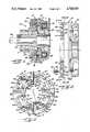
- FIG. 1is a cross-sectional view taken axially through a typical magnetic coupling equipped with a new and improved replaceable friction face incorporating the unique features of the present invention.
- FIG. 2is an enlarged view of the friction face illustrated in FIG. 1 and shows the friction face in exploded relation with its mounting member, the view of the friction face being taken substantially along the line 2--2 of FIG. 3.
- FIG. 3is a front elevational view of the friction face as seen along the line 3--3 of FIG. 2.
- FIG. 4is a front elevational view of one outer insert and one inner insert of the friction face.
- FIGS. 5 and 6are perspective views, on a reduced scale, of the outer and inner inserts, respectively, of FIG. 4 as seen from the front sides of the inserts.
- FIGS. 7, 8, and 9are cross-sections taken substantially along the lines 7--7, 8--8 and 9--9, respectively, of FIG. 4.
- FIG. 10is a rear elevational view of the friction face as seen along the line 10--10 of FIG. 2.
- FIG. 11is a rear elevational view of one outer insert and one inner insert of the friction face.
- FIGS. 12 and 13are perspective views, on a reduced scale, of the outer and inner inserts, respectively, of FIG. 11 as seen from the rear sides of the inserts.
- the inventionis shown in the drawings in conjunction with an electromagnetic coupling which herein is a clutch 15 for selectively transmitting torque from a rotary input member 16 to a rotary output member 17.
- the input memberis a sleeve adapted to be rotated by a shaft 18 which may be telescoped into and secured rigidly to the sleeve.
- the output memberis a hub journaled on the sleeve by a pair of bearings 19 and formed with a radially extending flange 20.
- the clutch 15includes an annular field member 21 of U-shaped cross-section and supported in a stationary position by a fixed mounting bracket 22.
- a bearing 23is located between the field member 21 and the input sleeve 16 to permit the latter to rotate within the former.
- Disposed within the field memberis a multiturn coil 24 which, when excited by a suitable dc voltage source, causes magnetic flux to thread out of one leg of the U-shaped field member and back into the other leg of the field member.
- a rotor 25Surrounding the forward portion of the field member 21 and connected to rotate with the input sleeve 16 is a rotor 25 having a generally circular and radially extending plate 26 (FIG. 2) located adjacent the free ends of the legs of the field member.
- the rotoris made of steel or other magnetic material and its plate 26 includes an annular band 27 of nonmagnetic material which separates the rotor into inner and outer annular sections of opposite magnetic polarity.
- armature 28Disposed in opposing relation with the plate 26 of the rotor 25 is a circular armature 28 (FIG. 1) made of steel.
- the armaturepreferably is formed as two semi-circular halves which are fastened to the flange 20 of the output hub 17 by eight angularly spaced screws 29 extending through alined holes 30 in the armature and the flange. By removing the screws, the two semi-circular halves of the armature may be slipped radially outwardly away from the input sleeve 16 for repair or replacement.
- the inner diameter of the rotor 25is splined to the input sleeve 16 as indicated at 31 so as to enable the rotor to move axially toward and away from the armature 28.
- magnetic fluxcrosses the air gap between the rotor and the armature and attracts the rotor axially toward the armature.
- the rotorfrictionally engages the armature and thereby couples the armature and the output hub 17 to rotate in unison with the rotor and the input sleeve 16.
- the rotorWhen the coil 24 is de-energized, the rotor no longer is magnetically attracted to the armature and no longer engages the armature with any significant frictional force. Accordingly, the input sleeve 16 rotates without transmitting any significant torque to the output hub 17.
- the rotorcarries a friction face 35 (FIG. 2) which also defines the magnetic poles of the rotor.
- the friction facepreferably is defined by two semi-circular sheets 36 (FIG. 3) of friction material (e.g., material similar to brake lining) which, when fit together, define a circular ring.
- the rear face of the friction ring 36is parallel to the forward face thereof and lies in face-to-face relation with the forward face of the mounting plate 26 of the rotor 25.
- An axially projecting annular flange 37(FIG. 2) is formed integrally with the outer periphery of the mounting plate and encircles the outer periphery of the rear portion of the friction ring.
- inserts 40 and 41which are made of steel or other low reluctance magnetic material and which define the poles of the rotor 25.
- the inserts 40are outer inserts located adjacent the outer periphery of the friction ring 36 there herein being a row of four outer inserts (see FIG. 10) spaced circumferentially from one another around the ring.
- Four inserts 41 which define inner insertsare spaced radially inwardly from the outer inserts and also are spaced circumferentially from one another around the ring.
- Each inner insert 41is substantially alined in a circumferential direction with an outer insert.
- the outer insertsdefine magnetic poles of one polarity while the inner inserts define magnetic poles of the opposite polarity.
- the inserts 40 and 41preferably are sintered from powdered metal. Initially, the friction material of the ring 36 also is in powder form. To make the friction face 35, the inserts are located in an appropriate mold. Thereafter, the mold is filled with powdered friction material which then is subjected to heat and pressure. The particulate friction material thus becomes bonded together to form the ring halves and also becomes bonded to the inserts to hold the inserts in place in the friction material.
- the inserts 40 and 41are formed with unique shoulder means which tightly interlock with the friction material of the ring 36 to hold the inserts rigidly against shifting in any direction relative to the ring.
- such interlockingprevents the inserts from skewing relative to the ring and holds the faces of the inserts in precisely parallel relation with the front and rear faces of the ring.
- an air gap of constant narrow widthis maintained between the armature 28 and the friction face 35 and, in addition, detrimental air gaps between the friction face and the mounting plate 26 of the rotor 25 are avoided.
- each outer insert 40is formed by an elongated and relatively thin arcuate plate 42 (FIG. 12).
- the extreme rear face 43 of the plateis flat and planar and defines the rear face of the insert.
- Formed integrally with and projecting forwardly from the forward side of the plateare two circumferentially spaced blocks 44 (FIG. 5) whose forward faces 45 define the extreme forward faces or pole faces of the insert.
- each outer insert 40is formed with shoulder means which intimately engage the friction material of the ring 36 to prevent the insert from shifting radially, circumferentially and axially relative to the friction material.
- the entire length of the outer edge portion of the rear face 43 of the plate 42is formed with an arcuate groove which defines an arcuate shoulder 50 facing in a radially outwardly direction and also a shoulder 51 facing axially rearwardly.
- the plate 42is formed with an arcuate groove which defines a radially inwardly facing shoulder 52 and an axially rearwardly facing shoulder 53.
- the two oppositely facing radial shoulders 50 and 52abut the friction material of the ring 36 and prevent any radial shifting of the rear portion of the insert 40.
- radially inward shifting of the insert 40is prevented by two radially extending shoulders 54 (FIG. 5) on the forward side of the plate 42 and extending from the ends of the blocks 44.
- the radially inner and outer sides of the blocks 44define shoulder means which also help prevent radial shifting of the outer insert.
- each outer insert 40intimately engages the friction material of the ring 36 to prevent rearward axial shifting of the insert. Forward axial shifting of the insert is prevented by the forward side of the plate 42 engaging the friction material, such side defining a shoulder facing oppositely of the shoulders 51 and 53.
- circumferential shifting of each outer insert 40is prevented by virtue of the friction material of the ring 36 engaging circumferentially oppositely facing shoulders defined by the two ends of each block 44.
- circumferentially oppositely facing shoulders 55are defined at the rear face 43 of the plate 42 by the ends of the groove adjacent the shoulders 52 and 53.
- Two additional circumferentially oppositely facing shoulders 56are defined at the ends of a rib on the forward side of the plate 42 adjacent the inner edge thereof, the inner side of the rib forming yet another radially inwardly facing shoulder.
- each outer insert 40is tightly locked within the friction material of the ring 36 and is prevented from skewing. Accordingly, the outer active pole faces 45 of the blocks 44 remain precisely parallel to the forward side of the ring 36 to maintain an air gap of constant axial width between the friction face 35 and the armature 28 even though the ring and the inserts are subjected to high pressure and even though the steel inserts and the friction material expand differentially when subjected to high temperature.
- each inner insert 41is constructed generally similar to the outer inserts 40 in order to enable the inner inserts also to interlock tightly with the friction material of the ring 36.
- each inner insert 41comprises two circumferentially spaced blocks 60 which are formed integrally with and project forwardly from the forward side of an elongated arcuate plate 61 having a flat and planar rear side 62.
- the rear side of the platedefines the rear face of the insert while the extreme forward sides 63 of the blocks define the pole faces of the insert.
- An arcuate groove(FIG. 13) is formed in the outer edge portion of the rear face 62 of each plate 61 and defines an arcuate shoulder 65 facing radially outwardly, a shoulder 66 facing axially rearwardly and a pair of oppositely facing circumferential shoulders 67.
- An arcuate grooveFormed along the inner edge portion of the rear face 62 of the plate 61 is an arcuate groove which defines a radially inwardly facing shoulder 68, an axially rearwardly facing shoulder 69 and a pair of oppositely facing circumferential shoulders 70.
- each plate 61also is formed with a radially outwardly facing shoulder 71 (FIG. 6) which coacts with the radially inner and outer sides of the blocks 60 to help prevent radial shifting of the inner insert 41.
- Circumferential shifting of the inner insertalso is prevented by the circumferentially oppositely facing shoulders defined by the two ends of each block 60 and by two additional circumferentially oppositely facing shoulders 72 defined by the ends of a rib on the forward side of the plate 61 adjacent the outer edge thereof.
- the outer side of the ribdefines yet another radially outwardly facing shoulder while the forward side of the plate 61 defines a shoulder facing oppositely of the shoulders 66 and 69 and acting to prevent forward axial shifting of the inner insert 41. Accordingly, the inner inserts 41 are tightly interlocked with the friction material of the ring 36 and are prevented from shifting in any direction relative to the friction material.
- the friction materialitself has a tendency to flex under the high heat and pressure applied to the friction face 35 during heavy duty operation.
- the inserts 40 and 41themselves are locked directly to the mounting plate 26 of the rotor 25 in order to reduce flexing of the friction material and to hold the rear sides of the inserts tightly against the mounting plate and thereby avoid air gaps between the inserts and the mounting plate.
- the radially outer edge of the plate 61 of each inner insert 41is formed with a pair of circumferentially spaced and radially outwardly projecting mounting ears 75 (FIG. 6) whose outer edges are formed with generally semi-circular notches 76 which open outwardly.
- Generally semi-circular and circumferentially spaced notches 77are formed in the radially inner edge of the plate 42 of each outer insert 40 and are alined circumferentially with the notches 76 of the circumferentially alined inner insert.
- the radially outer edges of the mounting ears 75are disposed closely adjacent to but are spaced radially from the radially inner edge of the outer insert 41 and thus each alined pair of notches 76 and 77 tends to approximate a full circle.
- a core pin(not shown) is placed in each pair of alined notches 76 and 77 and, as a result, a hole whose location corresponds to the location of the notches is formed through the friction material.
- An enlarged counterbore 80(FIG. 2) is molded in the friction material 36 forwardly of each hole, the counterbore resulting from the shape of the core pin.
- the several core pinshelp locate the inserts in the mold and, in addition, the inserts are fixtured very rigidly in the mold by locating pins (not shown) which extend through holes 81 formed through the blocks 44 and the plate 42 of each outer insert 40 and holes 82 formed through the blocks 60 and the plate 61 of each inner insert 41.
- alined notches 76 and 77 of the four pairs of inserts 40 and 41eight circumferentially spaced holes are formed through the friction face 35.
- Such holesare alined with circumferentially tapped holes 85 (FIG. 2) in the mounting plate 26 of the rotor 25.
- Fastenerswhich herein are in the form of cap screws 86 are threaded into the holes 85 with the heads 87 of the screws bearing against the bottoms of the counterbores 80. When the screws are tightened, their heads clamp against the inserts and thus anchor the inserts directly and rigidly to the mounting plate 26 of the rotor 25.
- the screwsare made of brass or other non-magnetic material in order to avoid magnetic bridges between the opposite poles defined by the outer and inner inserts.
- the rear faces 43 and 62 of the insertsare held in tight and permanent face-to-face engagement with the mounting plate and are prevented from pulling away therefrom as the forward or active face of the friction face 35 wears during service use. Accordingly, air gaps detrimental to the efficiency of the clutch 15 are prevented from developing between the inserts and the mounting plate.
- anchoring of the inserts directly to the mounting platepromotes more uniform wear of the inserts and the friction material of the ring 36 and reduces the tendency of the inserts to wear at a faster rate than the friction material.
- the holes defined by the alined notches 76 and 77are located on the same diameter as the holes 30 through the armature 28 and the flange 20 of the output hub 17 (see FIG. 1). Accordingly, after the armature 28 has been removed by removing the screws 29, a screwdriver may be inserted through the holes 30 to enable access to the screws 86. After those screws have been removed, the friction face 35 may be removed from the clutch 15 simply by slipping the two ring halves 36 radially outwardly.
Landscapes
- Engineering & Computer Science (AREA)
- General Engineering & Computer Science (AREA)
- Mechanical Engineering (AREA)
- Physics & Mathematics (AREA)
- Electromagnetism (AREA)
- Braking Arrangements (AREA)
Abstract
Description
Claims (14)
Priority Applications (8)
| Application Number | Priority Date | Filing Date | Title |
|---|---|---|---|
| US06/891,156US4718529A (en) | 1986-07-31 | 1986-07-31 | Friction face for a magnetic coupling |
| IT20981/87AIT1205160B (en) | 1986-07-31 | 1987-06-19 | FRICTION SURFACE FOR A MAGNETIC COUPLING |
| DE19873722146DE3722146A1 (en) | 1986-07-31 | 1987-07-04 | FRICTION COVER |
| DE8709246UDE8709246U1 (en) | 1986-07-31 | 1987-07-04 | Friction lining |
| CA000542165ACA1274793A (en) | 1986-07-31 | 1987-07-15 | Friction face for a magnetic coupling |
| JP62183254AJPH0678770B2 (en) | 1986-07-31 | 1987-07-22 | Friction surface member for electromagnetic coupling |
| FR878710457AFR2602563B1 (en) | 1986-07-31 | 1987-07-23 | FRICTION FACE FOR MAGNETIC COUPLING |
| GB8718233AGB2193272B (en) | 1986-07-31 | 1987-07-31 | Friction face for a magnetic coupling |
Applications Claiming Priority (1)
| Application Number | Priority Date | Filing Date | Title |
|---|---|---|---|
| US06/891,156US4718529A (en) | 1986-07-31 | 1986-07-31 | Friction face for a magnetic coupling |
Publications (1)
| Publication Number | Publication Date |
|---|---|
| US4718529Atrue US4718529A (en) | 1988-01-12 |
Family
ID=25397718
Family Applications (1)
| Application Number | Title | Priority Date | Filing Date |
|---|---|---|---|
| US06/891,156Expired - LifetimeUS4718529A (en) | 1986-07-31 | 1986-07-31 | Friction face for a magnetic coupling |
Country Status (7)
| Country | Link |
|---|---|
| US (1) | US4718529A (en) |
| JP (1) | JPH0678770B2 (en) |
| CA (1) | CA1274793A (en) |
| DE (2) | DE8709246U1 (en) |
| FR (1) | FR2602563B1 (en) |
| GB (1) | GB2193272B (en) |
| IT (1) | IT1205160B (en) |
Cited By (8)
| Publication number | Priority date | Publication date | Assignee | Title |
|---|---|---|---|---|
| US4896757A (en)* | 1988-09-06 | 1990-01-30 | Facet Enterprises, Incorporated | Bolt on electromagnetic fan clutch |
| US20050275967A1 (en)* | 2004-05-27 | 2005-12-15 | Olien Neil T | Products and processes for providing haptic feedback in resistive interface devices |
| US20060033703A1 (en)* | 2004-08-11 | 2006-02-16 | Olien Neil T | Systems and methods for providing friction in a haptic feedback device |
| US20060044271A1 (en)* | 2004-08-24 | 2006-03-02 | Anastas George V | Magnetic actuator for providing haptic feedback |
| US20060061558A1 (en)* | 2004-09-20 | 2006-03-23 | Danny Grant | Products and processes for providing multimodal feedback in a user interface device |
| US20060144666A1 (en)* | 2004-12-24 | 2006-07-06 | Masashi Aikawa | Magnetic-path member, electromagnetic coupling device using magnetic-path member, and method of manufacturing magnetic-path member |
| DE102007013401A1 (en)* | 2007-03-20 | 2008-09-25 | Rex Industrie-Produkte Graf Von Rex Gmbh | Brake disc, especially for magnetic brakes |
| KR20140134275A (en)* | 2012-02-10 | 2014-11-21 | 크노르-브렘제 시스테메 퓌어 누츠파조이게 게엠베하 | Lining wear adjustment device for a disc brake |
Families Citing this family (2)
| Publication number | Priority date | Publication date | Assignee | Title |
|---|---|---|---|---|
| DE4343429C2 (en)* | 1993-12-18 | 1999-08-12 | Schaeffler Waelzlager Ohg | Tensioning device for a belt or chain drive |
| DE102010055647A1 (en)* | 2010-12-22 | 2012-06-28 | Volkswagen Aktiengesellschaft | Friction device for magnetic coupling device, comprises supporting plate and friction body having friction surface, where multiple magnetized guide bodies are arranged at supporting plate |
Citations (9)
| Publication number | Priority date | Publication date | Assignee | Title |
|---|---|---|---|---|
| US2541979A (en)* | 1947-11-21 | 1951-02-20 | Hans R Amundsen | Friction brake and clutch |
| US2982385A (en)* | 1957-10-21 | 1961-05-02 | Eaton Mfg Co | Electromagnetic devices with friction lining |
| DE1133604B (en)* | 1960-05-10 | 1962-07-19 | Stromag Maschf | Friction disc for electromagnetically operated clutches and brakes |
| US3426875A (en)* | 1966-08-19 | 1969-02-11 | Bosch Gmbh Robert | Electromagnetic clutch |
| US4172242A (en)* | 1978-05-03 | 1979-10-23 | Warner Electric Brake & Clutch Company | Electromagnet for use with a brake or the like |
| JPS55720A (en)* | 1978-06-19 | 1980-01-07 | Masanobu Suzuki | Fluid reforming device and its method |
| US4344056A (en)* | 1980-07-31 | 1982-08-10 | Warner Electric Brake & Clutch Company | Electromagnet with replaceable friction face |
| US4413717A (en)* | 1978-03-27 | 1983-11-08 | Hitachi, Ltd. | Electromagnetic clutch and method of manufacture |
| US4512450A (en)* | 1981-11-02 | 1985-04-23 | Babcock Daniel A | Clutch brake |
Family Cites Families (11)
| Publication number | Priority date | Publication date | Assignee | Title |
|---|---|---|---|---|
| GB756202A (en)* | 1954-03-04 | 1956-08-29 | Rapid Magnetic Machines Ltd | Improvements in or relating to magnetic clutches and brakes |
| FR1304241A (en)* | 1961-10-18 | 1962-09-21 | Stromag Maschf | Friction disc for electromagnetically controlled couplings and brakes |
| DE1475414A1 (en)* | 1965-04-14 | 1969-06-04 | Ortlinghaus Werke Gmbh | Electromagnetic friction clutch or brake |
| US3444970A (en)* | 1967-05-05 | 1969-05-20 | Warner Electric Brake & Clutch | Magnetic friction coupling with partly laminated flux circuit |
| DE2113275A1 (en)* | 1971-03-19 | 1972-09-21 | Zinser Textilmaschinen Gmbh | Spinning or twisting spindle |
| JPS534369Y2 (en)* | 1974-05-31 | 1978-02-03 | ||
| GB1495815A (en)* | 1976-03-26 | 1977-12-21 | Cutler Hammer World Trade Inc | Miniature clutch or brake devices |
| JPS5839257B2 (en)* | 1979-01-08 | 1983-08-29 | 株式会社日立製作所 | electromagnetic clutch |
| JPS55161141U (en)* | 1979-05-04 | 1980-11-19 | ||
| JPS55161143U (en)* | 1979-05-04 | 1980-11-19 | ||
| US4496922A (en)* | 1983-12-05 | 1985-01-29 | Warner Electric Brake & Clutch Company | Electromagnetically released coupling |
- 1986
- 1986-07-31USUS06/891,156patent/US4718529A/ennot_activeExpired - Lifetime
- 1987
- 1987-06-19ITIT20981/87Apatent/IT1205160B/enactive
- 1987-07-04DEDE8709246Upatent/DE8709246U1/ennot_activeExpired
- 1987-07-04DEDE19873722146patent/DE3722146A1/enactiveGranted
- 1987-07-15CACA000542165Apatent/CA1274793A/ennot_activeExpired
- 1987-07-22JPJP62183254Apatent/JPH0678770B2/ennot_activeExpired - Lifetime
- 1987-07-23FRFR878710457Apatent/FR2602563B1/ennot_activeExpired - Lifetime
- 1987-07-31GBGB8718233Apatent/GB2193272B/ennot_activeExpired - Lifetime
Patent Citations (9)
| Publication number | Priority date | Publication date | Assignee | Title |
|---|---|---|---|---|
| US2541979A (en)* | 1947-11-21 | 1951-02-20 | Hans R Amundsen | Friction brake and clutch |
| US2982385A (en)* | 1957-10-21 | 1961-05-02 | Eaton Mfg Co | Electromagnetic devices with friction lining |
| DE1133604B (en)* | 1960-05-10 | 1962-07-19 | Stromag Maschf | Friction disc for electromagnetically operated clutches and brakes |
| US3426875A (en)* | 1966-08-19 | 1969-02-11 | Bosch Gmbh Robert | Electromagnetic clutch |
| US4413717A (en)* | 1978-03-27 | 1983-11-08 | Hitachi, Ltd. | Electromagnetic clutch and method of manufacture |
| US4172242A (en)* | 1978-05-03 | 1979-10-23 | Warner Electric Brake & Clutch Company | Electromagnet for use with a brake or the like |
| JPS55720A (en)* | 1978-06-19 | 1980-01-07 | Masanobu Suzuki | Fluid reforming device and its method |
| US4344056A (en)* | 1980-07-31 | 1982-08-10 | Warner Electric Brake & Clutch Company | Electromagnet with replaceable friction face |
| US4512450A (en)* | 1981-11-02 | 1985-04-23 | Babcock Daniel A | Clutch brake |
Cited By (17)
| Publication number | Priority date | Publication date | Assignee | Title |
|---|---|---|---|---|
| US4896757A (en)* | 1988-09-06 | 1990-01-30 | Facet Enterprises, Incorporated | Bolt on electromagnetic fan clutch |
| US7522152B2 (en) | 2004-05-27 | 2009-04-21 | Immersion Corporation | Products and processes for providing haptic feedback in resistive interface devices |
| US20050275967A1 (en)* | 2004-05-27 | 2005-12-15 | Olien Neil T | Products and processes for providing haptic feedback in resistive interface devices |
| US8154512B2 (en) | 2004-05-27 | 2012-04-10 | Immersion Coporation | Products and processes for providing haptic feedback in resistive interface devices |
| US20090231113A1 (en)* | 2004-05-27 | 2009-09-17 | Olien Neil T | Products and Processes For Providing Haptic Feedback In Resistive Interface Devices |
| US8441433B2 (en) | 2004-08-11 | 2013-05-14 | Immersion Corporation | Systems and methods for providing friction in a haptic feedback device |
| US20060033703A1 (en)* | 2004-08-11 | 2006-02-16 | Olien Neil T | Systems and methods for providing friction in a haptic feedback device |
| US8013847B2 (en) | 2004-08-24 | 2011-09-06 | Immersion Corporation | Magnetic actuator for providing haptic feedback |
| US20060044271A1 (en)* | 2004-08-24 | 2006-03-02 | Anastas George V | Magnetic actuator for providing haptic feedback |
| US20060061558A1 (en)* | 2004-09-20 | 2006-03-23 | Danny Grant | Products and processes for providing multimodal feedback in a user interface device |
| US9046922B2 (en) | 2004-09-20 | 2015-06-02 | Immersion Corporation | Products and processes for providing multimodal feedback in a user interface device |
| US20060144666A1 (en)* | 2004-12-24 | 2006-07-06 | Masashi Aikawa | Magnetic-path member, electromagnetic coupling device using magnetic-path member, and method of manufacturing magnetic-path member |
| US7592890B2 (en)* | 2004-12-24 | 2009-09-22 | Gkn Driveline Torque Technology Kk | Magnetic-path member, electromagnetic coupling device using magnetic-path member, and method of manufacturing magnetic-path member |
| DE102007013401A1 (en)* | 2007-03-20 | 2008-09-25 | Rex Industrie-Produkte Graf Von Rex Gmbh | Brake disc, especially for magnetic brakes |
| KR20140134275A (en)* | 2012-02-10 | 2014-11-21 | 크노르-브렘제 시스테메 퓌어 누츠파조이게 게엠베하 | Lining wear adjustment device for a disc brake |
| US20140345985A1 (en)* | 2012-02-10 | 2014-11-27 | Knorr-Bremse Systeme Fuer Nutzfahrzeuge Gmbh | Lining Wear Adjustment Device for a Disc Brake |
| US10060490B2 (en)* | 2012-02-10 | 2018-08-28 | Knorr-Bremse Systeme Fuer Nutzfahrzeuge Gmbh | Lining wear adjustment device for a disc brake |
Also Published As
| Publication number | Publication date |
|---|---|
| DE3722146A1 (en) | 1988-02-04 |
| CA1274793A (en) | 1990-10-02 |
| GB8718233D0 (en) | 1987-09-09 |
| DE3722146C2 (en) | 1990-09-13 |
| FR2602563B1 (en) | 1992-09-04 |
| GB2193272B (en) | 1990-07-04 |
| IT8720981A0 (en) | 1987-06-19 |
| IT1205160B (en) | 1989-03-15 |
| FR2602563A1 (en) | 1988-02-12 |
| JPS6338725A (en) | 1988-02-19 |
| JPH0678770B2 (en) | 1994-10-05 |
| GB2193272A (en) | 1988-02-03 |
| DE8709246U1 (en) | 1987-09-03 |
Similar Documents
| Publication | Publication Date | Title |
|---|---|---|
| US4718529A (en) | Friction face for a magnetic coupling | |
| US2919777A (en) | Magnetic torque producing device | |
| KR101031611B1 (en) | Rotary coupling device | |
| US3263784A (en) | Magnetic clutch | |
| JPS58102830A (en) | Assembly of armature of electromagnetic coupling | |
| US5971121A (en) | Mag stop clutch with center pole | |
| US20120175214A1 (en) | Rotational coupling device with wear compensation structure | |
| US2739684A (en) | Pole piece unit for magnets | |
| US2488827A (en) | Magnetic coupling | |
| US3624767A (en) | Self-adjusting clutch or brake | |
| US4681197A (en) | Electromagnetic clutches and brakes | |
| US3338349A (en) | Electric motor mounted magnetic friction brake | |
| JP3082565B2 (en) | Non-excitation actuated electromagnetic brake / clutch | |
| US2695687A (en) | Magnetic friction device with replaceable friction face | |
| US2970681A (en) | Wear adjuster for magnetic friction devices | |
| US3530416A (en) | Magnetic element for stationary field clutches | |
| US3669231A (en) | Synchronized electromagnetic clutch | |
| US2919776A (en) | Magnetic torque producing device | |
| US2914714A (en) | Permanent magnet torque producing device | |
| US2853165A (en) | Magnetic friction torque applying apparatus | |
| US3586145A (en) | Electromagnetic clutch having stacked armature disks | |
| US1258115A (en) | Clutch. | |
| US2864478A (en) | Pole piece unit for magnets | |
| JP5509052B2 (en) | Electromagnetic clutch | |
| US3863743A (en) | Subassembly for magnetic friction coupling |
Legal Events
| Date | Code | Title | Description |
|---|---|---|---|
| AS | Assignment | Owner name:WARNER ELECTRIC BRAKE & CLUTCH COMPANY, 449 GARDNE Free format text:ASSIGNMENT OF ASSIGNORS INTEREST.;ASSIGNORS:KROEGER, EDWARD R.;DVORAK, RICHARD C.;REEL/FRAME:004620/0608 Effective date:19860725 | |
| STCF | Information on status: patent grant | Free format text:PATENTED CASE | |
| FEPP | Fee payment procedure | Free format text:PAYOR NUMBER ASSIGNED (ORIGINAL EVENT CODE: ASPN); ENTITY STATUS OF PATENT OWNER: LARGE ENTITY | |
| FPAY | Fee payment | Year of fee payment:4 | |
| FPAY | Fee payment | Year of fee payment:8 | |
| FEPP | Fee payment procedure | Free format text:PAYOR NUMBER ASSIGNED (ORIGINAL EVENT CODE: ASPN); ENTITY STATUS OF PATENT OWNER: LARGE ENTITY Free format text:PAYER NUMBER DE-ASSIGNED (ORIGINAL EVENT CODE: RMPN); ENTITY STATUS OF PATENT OWNER: LARGE ENTITY | |
| FPAY | Fee payment | Year of fee payment:12 | |
| AS | Assignment | Owner name:BANK OF NOVA SCOTIA, AS ADMINISTRATIVE AGENT, NEW Free format text:SECURITY INTEREST;ASSIGNOR:WARNER ELECTRIC TECHNOLOGY, INC.;REEL/FRAME:010676/0916 Effective date:20000229 | |
| AS | Assignment | Owner name:WARNER ELECTRIC TECHNOLOGY, INC., VIRGINIA Free format text:ASSIGNMENT OF ASSIGNORS INTEREST;ASSIGNOR:DANA CORPORATION;REEL/FRAME:010832/0196 Effective date:20000229 | |
| AS | Assignment | Owner name:WARNER ELECTRIC (HOLDING) SAS, VIRGINIA Free format text:RELEASE OF SECURITY INTEREST;ASSIGNOR:BANK OF NOVA SCOTIA, THE;REEL/FRAME:014128/0962 Effective date:20030530 Owner name:WARNER ELECTRIC GROUP GMPH, GERMANY Free format text:RELEASE OF SECURITY INTEREST;ASSIGNOR:BANK OF NOVA SCOTIA, THE;REEL/FRAME:014128/0962 Effective date:20030530 Owner name:WARNER ELECTRIC GROUP, INC., VIRGINIA Free format text:RELEASE OF SECURITY INTEREST;ASSIGNOR:BANK OF NOVA SCOTIA, THE;REEL/FRAME:014128/0962 Effective date:20030530 Owner name:WARNER ELECTRIC HOLDING, INC., FRANCE Free format text:RELEASE OF SECURITY INTEREST;ASSIGNOR:BANK OF NOVA SCOTIA, THE;REEL/FRAME:014128/0962 Effective date:20030530 Owner name:WARNER ELECTRIC UK GROUP LTD., ENGLAND Free format text:RELEASE OF SECURITY INTEREST;ASSIGNOR:BANK OF NOVA SCOTIA, THE;REEL/FRAME:014128/0962 Effective date:20030530 | |
| AS | Assignment | Owner name:BANK OF NOVA SCOTIA, THE, NEW YORK Free format text:SECURITY INTEREST;ASSIGNORS:COLFAX CORPORATION;CLFX CORPORATION;IMO HOLDINGS, INC.;AND OTHERS;REEL/FRAME:014250/0339 Effective date:20030530 | |
| AS | Assignment | Owner name:WARNER ELECTRIC TECHNOLOGY, LLC, VIRGINIA Free format text:CONVERSION;ASSIGNOR:WARNER ELECTRIC TECHNOLOGY, INC.;REEL/FRAME:015083/0777 Effective date:20040702 | |
| AS | Assignment | Owner name:WARNER ELECTRIC TECHNOLOGY LLC FKA WARNER ELECTRIC Free format text:RELEASE OF SECURITY INTEREST GRANTED 5/30/2003 AT REEL/FRAME 014250/0339 AND RE-RELEASE OF SECURITY INTEREST GRANTED ON 2/29/2000 AT REEL/FRAME 010676/0916;ASSIGNOR:THE BANK OF NOVA SCOTIA;REEL/FRAME:015400/0011 Effective date:20041130 | |
| AS | Assignment | Owner name:WELLS FARGO FOOTHILL, INC., CALIFORNIA Free format text:SECURITY AGREEMENT;ASSIGNORS:ALTRA INDUSTRIAL MOTION, INC.;WARNER ELECTRIC LLC;KILIAN MANUFACTURING CORPORATION;AND OTHERS;REEL/FRAME:015409/0091 Effective date:20041130 | |
| AS | Assignment | Owner name:THE BANK OF NEW YORK TRUST COMPANY, N.A., FLORIDA Free format text:SECURITY AGREEMENT;ASSIGNORS:WARNER ELECTRIC TECHNOLOGY LLC;BOSTON GEAR LLC;REEL/FRAME:015418/0123 Effective date:20041130 | |
| AS | Assignment | Owner name:WARNER ELECTRIC, INC., VIRGINIA Free format text:RELEASE BY SECURED PARTY;ASSIGNOR:THE BANK OF NOVA SCOTIA;REEL/FRAME:020941/0226 Effective date:20080501 Owner name:AMERICAN ENTERPRISES MPT HOLDINGS, L.P., VIRGINIA Free format text:RELEASE BY SECURED PARTY;ASSIGNOR:THE BANK OF NOVA SCOTIA;REEL/FRAME:020941/0226 Effective date:20080501 Owner name:FORMSPRAG LLC, VIRGINIA Free format text:RELEASE BY SECURED PARTY;ASSIGNOR:THE BANK OF NOVA SCOTIA;REEL/FRAME:020941/0226 Effective date:20080501 Owner name:NETZCH USA CORPORATION, VIRGINIA Free format text:RELEASE BY SECURED PARTY;ASSIGNOR:THE BANK OF NOVA SCOTIA;REEL/FRAME:020941/0226 Effective date:20080501 Owner name:AMERIDRIVES INTERNATIONAL, L.P., VIRGINIA Free format text:RELEASE BY SECURED PARTY;ASSIGNOR:THE BANK OF NOVA SCOTIA;REEL/FRAME:020941/0226 Effective date:20080501 Owner name:NUTTALL GEAR LLC, VIRGINIA Free format text:RELEASE BY SECURED PARTY;ASSIGNOR:THE BANK OF NOVA SCOTIA;REEL/FRAME:020941/0226 Effective date:20080501 Owner name:WARNER ELECTRIC TECHNOLOGY, INC., VIRGINIA Free format text:RELEASE BY SECURED PARTY;ASSIGNOR:THE BANK OF NOVA SCOTIA;REEL/FRAME:020941/0226 Effective date:20080501 Owner name:AMERICAN ENTERPRISES MPT CORP., VIRGINIA Free format text:RELEASE BY SECURED PARTY;ASSIGNOR:THE BANK OF NOVA SCOTIA;REEL/FRAME:020941/0226 Effective date:20080501 Owner name:WARNER ELECTRIC FINANCE COMPANY, INC., VIRGINIA Free format text:RELEASE BY SECURED PARTY;ASSIGNOR:THE BANK OF NOVA SCOTIA;REEL/FRAME:020941/0226 Effective date:20080501 Owner name:WARNER ELECTRIC INTERNATIONAL HOLDING, INC., VIRGI Free format text:RELEASE BY SECURED PARTY;ASSIGNOR:THE BANK OF NOVA SCOTIA;REEL/FRAME:020941/0226 Effective date:20080501 Owner name:INCOM TRANSPORTATION, INC., VIRGINIA Free format text:RELEASE BY SECURED PARTY;ASSIGNOR:THE BANK OF NOVA SCOTIA;REEL/FRAME:020941/0226 Effective date:20080501 Owner name:WARNER ELECTRIC HOLDING, INC., VIRGINIA Free format text:RELEASE BY SECURED PARTY;ASSIGNOR:THE BANK OF NOVA SCOTIA;REEL/FRAME:020941/0226 Effective date:20080501 Owner name:IMO INDUSTRIES, INC., VIRGINIA Free format text:RELEASE BY SECURED PARTY;ASSIGNOR:THE BANK OF NOVA SCOTIA;REEL/FRAME:020941/0226 Effective date:20080501 Owner name:IMO HOLDINGS, INC., VIRGINIA Free format text:RELEASE BY SECURED PARTY;ASSIGNOR:THE BANK OF NOVA SCOTIA;REEL/FRAME:020941/0226 Effective date:20080501 Owner name:WARREN PUMPS INC., VIRGINIA Free format text:RELEASE BY SECURED PARTY;ASSIGNOR:THE BANK OF NOVA SCOTIA;REEL/FRAME:020941/0226 Effective date:20080501 Owner name:COLFAX CORPORATION, VIRGINIA Free format text:RELEASE BY SECURED PARTY;ASSIGNOR:THE BANK OF NOVA SCOTIA;REEL/FRAME:020941/0226 Effective date:20080501 Owner name:CLFX CORPORATION, VIRGINIA Free format text:RELEASE BY SECURED PARTY;ASSIGNOR:THE BANK OF NOVA SCOTIA;REEL/FRAME:020941/0226 Effective date:20080501 Owner name:CONSTELLATION PUMPS CORPORATION, VIRGINIA Free format text:RELEASE BY SECURED PARTY;ASSIGNOR:THE BANK OF NOVA SCOTIA;REEL/FRAME:020941/0226 Effective date:20080501 | |
| AS | Assignment | Owner name:AMERICAN ENTERPRISES MPT CORP.,MASSACHUSETTS Free format text:RELEASE BY SECURED PARTY;ASSIGNOR:WELLS FARGO FOOTHILL, INC.;REEL/FRAME:023915/0715 Effective date:20100129 Owner name:AMERIDRIVES INTERNATIONAL L.P.,PENNSYLVANIA Free format text:RELEASE BY SECURED PARTY;ASSIGNOR:WELLS FARGO FOOTHILL, INC.;REEL/FRAME:023915/0715 Effective date:20100129 Owner name:AMERICAN ENTERPRISES MPT HOLDINGS, L.P.,MASSACHUSE Free format text:RELEASE BY SECURED PARTY;ASSIGNOR:WELLS FARGO FOOTHILL, INC.;REEL/FRAME:023915/0715 Effective date:20100129 Owner name:KILIAN MANUFACTURING CORPORATION,NEW YORK Free format text:RELEASE BY SECURED PARTY;ASSIGNOR:WELLS FARGO FOOTHILL, INC.;REEL/FRAME:023915/0715 Effective date:20100129 Owner name:ALTRA INDUSTRIAL MOTION, INC.,MASSACHUSETTS Free format text:RELEASE BY SECURED PARTY;ASSIGNOR:WELLS FARGO FOOTHILL, INC.;REEL/FRAME:023915/0715 Effective date:20100129 Owner name:BOSTON GEAR LLC,MASSACHUSETTS Free format text:RELEASE BY SECURED PARTY;ASSIGNOR:WELLS FARGO FOOTHILL, INC.;REEL/FRAME:023915/0715 Effective date:20100129 Owner name:WARNER ELECTRIC TECHNOLOGY LLC,MASSACHUSETTS Free format text:RELEASE BY SECURED PARTY;ASSIGNOR:WELLS FARGO FOOTHILL, INC.;REEL/FRAME:023915/0715 Effective date:20100129 Owner name:NUTTALL GEAR LLC,NEW YORK Free format text:RELEASE BY SECURED PARTY;ASSIGNOR:WELLS FARGO FOOTHILL, INC.;REEL/FRAME:023915/0715 Effective date:20100129 Owner name:THE KILIAN COMPANY,NEW YORK Free format text:RELEASE BY SECURED PARTY;ASSIGNOR:WELLS FARGO FOOTHILL, INC.;REEL/FRAME:023915/0715 Effective date:20100129 Owner name:FORMSPRAG LLC,MICHIGAN Free format text:RELEASE BY SECURED PARTY;ASSIGNOR:WELLS FARGO FOOTHILL, INC.;REEL/FRAME:023915/0715 Effective date:20100129 Owner name:WARNER ELECTRIC INTERNATIONAL HOLDING, INC.,MASSAC Free format text:RELEASE BY SECURED PARTY;ASSIGNOR:WELLS FARGO FOOTHILL, INC.;REEL/FRAME:023915/0715 Effective date:20100129 Owner name:WARNER ELECTRIC LLC,ILLINOIS Free format text:RELEASE BY SECURED PARTY;ASSIGNOR:WELLS FARGO FOOTHILL, INC.;REEL/FRAME:023915/0715 Effective date:20100129 | |
| AS | Assignment | Owner name:BOSTON GEAR LLC,MASSACHUSETTS Free format text:RELEASE BY SECURED PARTY;ASSIGNOR:THE BANK OF NEW YORK MELLON TRUST COMPANY, N.A. (F/K/A THE BANK OF NEW YORK TRUST COMPANY, N.A.);REEL/FRAME:024233/0603 Effective date:20100409 Owner name:WARNER ELECTRIC TECHNOLOGY LLC,MASSACHUSETTS Free format text:RELEASE BY SECURED PARTY;ASSIGNOR:THE BANK OF NEW YORK MELLON TRUST COMPANY, N.A. (F/K/A THE BANK OF NEW YORK TRUST COMPANY, N.A.);REEL/FRAME:024233/0603 Effective date:20100409 |