US4718419A - Snare assembly for endoscope - Google Patents
Snare assembly for endoscopeDownload PDFInfo
- Publication number
- US4718419A US4718419AUS06/890,629US89062986AUS4718419AUS 4718419 AUS4718419 AUS 4718419AUS 89062986 AUS89062986 AUS 89062986AUS 4718419 AUS4718419 AUS 4718419A
- Authority
- US
- United States
- Prior art keywords
- snare
- stopper
- tube
- slide
- end portion
- Prior art date
- Legal status (The legal status is an assumption and is not a legal conclusion. Google has not performed a legal analysis and makes no representation as to the accuracy of the status listed.)
- Expired - Lifetime
Links
Images


Classifications
- A—HUMAN NECESSITIES
- A61—MEDICAL OR VETERINARY SCIENCE; HYGIENE
- A61B—DIAGNOSIS; SURGERY; IDENTIFICATION
- A61B17/00—Surgical instruments, devices or methods
- A61B17/32—Surgical cutting instruments
- A61B17/3205—Excision instruments
- A61B17/32056—Surgical snare instruments
- A—HUMAN NECESSITIES
- A61—MEDICAL OR VETERINARY SCIENCE; HYGIENE
- A61B—DIAGNOSIS; SURGERY; IDENTIFICATION
- A61B18/00—Surgical instruments, devices or methods for transferring non-mechanical forms of energy to or from the body
- A61B18/04—Surgical instruments, devices or methods for transferring non-mechanical forms of energy to or from the body by heating
- A61B18/12—Surgical instruments, devices or methods for transferring non-mechanical forms of energy to or from the body by heating by passing a current through the tissue to be heated, e.g. high-frequency current
- A61B18/14—Probes or electrodes therefor
- A61B18/1492—Probes or electrodes therefor having a flexible, catheter-like structure, e.g. for heart ablation
- A—HUMAN NECESSITIES
- A61—MEDICAL OR VETERINARY SCIENCE; HYGIENE
- A61B—DIAGNOSIS; SURGERY; IDENTIFICATION
- A61B18/00—Surgical instruments, devices or methods for transferring non-mechanical forms of energy to or from the body
- A61B18/04—Surgical instruments, devices or methods for transferring non-mechanical forms of energy to or from the body by heating
- A61B18/12—Surgical instruments, devices or methods for transferring non-mechanical forms of energy to or from the body by heating by passing a current through the tissue to be heated, e.g. high-frequency current
- A61B18/14—Probes or electrodes therefor
- A61B2018/1405—Electrodes having a specific shape
- A61B2018/1407—Loop
- A61B2018/141—Snare
Definitions
- This inventionrelates to a snare assembly which is inserted into a region of interest of a human being through a channel of an associated endoscope, and in particular to a snare assembly which can cut, for example, a polyp in a body cavity of a human being by a current of a high frequency supplied to that location.
- a conventional snare assembly for endoscopeis disclosed in, for example, Japanese Utility Model Disclosure (KOKAI) No. 55-126811.
- a snareis inserted into a sheath such that a folded end portion is provided at the forward end portion of the snare with first a relatively long snare section and second a relatively short snare section defined by a folded point.
- a slide memberis fixed to the end portion of the second snare section. The slide member has a small bore through which the end portion of the first snare section is inserted.
- a latching memberis attached to the first snare section between the folded end portion and the slide member and, upon pulling the end of the first snare section, abuts against the slide member to move the slide member.
- a stopperis mounted near the forward end of the sheath to stop the slide member from being dropped off the sheath.
- the end portion of the first snare sectionis pushed ahead, the slide member is advanced to a position of the stopper where it is stopped due to an abutment thereagainst.
- the first snare sectionis curved to provide a semi-circular loop. With such a polyp entrapped within the loop, the end portion of the first snare section is withdrawn to permit the polyp to be tightened around the loop. A current of a high frequency is supplied to that location to cause the polyp to be rejected.
- a snare assembly for endoscopewhich comprises:
- a flexible outer tubehaving a forward end and base end
- the inner tubeinserted into the outer tube such that it can be moved back and forth, the inner tube having a forward end and base end;
- fixing meansmounted on the base ends of the inner and outer tubes and, after a relative position of the inner tube to the outer tube has been adjusted, fixing the inner tube to the outer tube at that relative position.
- Another snare assemblyis also disclosed which comprises:
- a folded snareinserted into the tube to be movable back and forth and having a folded end portion and a relatively short snare section;
- stopper meansmovable back and forth and adapted to abut against the slide means upon the forward movement of the snare;
- fixing meansguiding the slide means and stopper means in a moving direction and, after a relative position between the stopper means and the tube has been adjusted, fixing the stopper means and tube at that relative position.
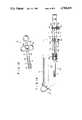
- FIGS. 1 and 2each are a cross-sectional view in side elevation showing a snare assembly for endoscope according to one embodiment of this invention
- FIGS. 3 and 4each are a cross-sectional view in side elevation showing a variant of an outer tube of the snare assembly of this invention
- FIGS. 5 and 6each are a cross-sectional view in side elevation showing another variant of a fixing means of the snare assembly of this invention
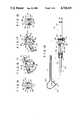
- FIGS. 7 and 8each are a cross-sectional view in side elevation showing the snare assembly according to another embodiment of this invention.
- FIG. 9is a perspective view showing a sheath assembly for the snare assembly of this invention.
- FIGS. 10 and 11each are a perspective view showing a variant of the sheath assembly for the snare assembly of this invention.
- FIG. 12is a cross-sectional view in side elevation showing a second variant of the sheath assembly of the snare assembly of this invention.
- FIG. 13is a plain view showing an operation device associated with the second variant of the sheath assembly of FIG. 12;
- FIGS. 14 and 19are a cross-sectional views in side elevation schematically showing the sheath assembly and associated operation device
- FIGS. 15 and 18each are a cross-sectional view, as taken along I--I line in FIG. 14, showing the operation device of FIG. 14;
- FIGS. 16 and 17are a perspective views schematically showing a guide rail and stopper for the operation device of the snare assembly of this invention.
- FIGS. 20 and 23each are a cross-sectional view schematically showing a variant of the operation device attached to the sheath assembly of the snare assembly of this invention.
- FIG. 21is a cross-sectional view showing the operation device, as taken along II--II line in FIG. 20;
- FIG. 22is a cross-sectional view, as taken along III--III line in FIG. 20.
- FIGS. 1 and 2shown a snare assembly for endoscope according to a first embodiment of this invention.
- outer tube 10is formed of a flexible resin having an electrical insulation property, such as Teflon, and has narrow section 10A at the forward end.
- Cylindrical rigid tip 12, such as a metalis fitted inside outer tube 10 and has the same inner diameter as that of narrow section 10A.
- Cylindrical cap 14made of, for example, a metal is attached to the base end portion of outer tube 10 and set screw 16 is screwed to cylindrical cap 14.
- Inner tube 18is formed of a flexible resin having an electrical insulation property, such as Teflon, and inserted into outer tube 10 such that snare 20 is inserted into inner tube 10.
- Cylindrical stopper 22is fitted inside the forward end portion of inner tube 18.
- Cap 26is attached to the base portion of inner tube 18 and has grooves 24 formed at predetermined pitches on its outer surface. Insertion hole 28 is formed in cap 26 in a longitudinal direction and fixing section 30 is formed at the base portion of cap 26 to fix an operation device, not shown, there.
- snare 20The forward end portion of snare 20 is folded at a proper place to provide folded point 21 with a first, relatively long snare section 20A and second, relatively short snare section 20B defined thereby.
- Slide member 34is fixed to the end of second snare section 20B of snare 20.
- Slide member 34is movably disposed within inner tube 18 such that first snare section 20A is movably inserted into hole 36 of slide member 34.
- Engaging member 38is fixed, ahead of hole 36 of slide member 34, to first snare section 20A to move slide member 34 upon withdrawing the end of first snare section 20A.
- first snare section 20Aextends toward the base portion of inner tube 18 through the hole 36 of slide member 34, and thick operation wire 32 is connected to the base end portion of first snare section 20A.
- thick operation wire 32is connected to the base end portion of first snare section 20A.
- center wiresuch as operation wire 32.
- the other wires around center wire 20are deposited, at the forward end, with solder 44.
- Operation rod 40is connected at one end to the base end of operation wire 32 and at the other end portion to an operation device, not shown, by means of fixing member 42.
- Snare 20is freely moved back and forth by pulling and pushing operation rod 40.
- slide member 34is advanced into abutment with stopper 22 with the result that further advance of folded point 21 of snare 20 is stopped.
- folded point 21 of snare 20is located at the most forward position.
- Further advance of operation rod 40causes first snare section 20A to be outwardly curved from folded point 21 to provide a substantially elliptical loop, as shown in FIG. 1, in which case the length B of first snare section 20B extending from the forward end of outer tube 10 to folded point 21 is constant.
- First snare section 20Ais moved back and forth by pulling and pushing operation rod 40 so that the aforementioned loop is closed and opened.
- cap 26is pulled as shown, for example, in FIG. 2 and thus inner tube 18 is retracted relative to outer tube 10 in a direction of the base end of outer tube 10, so that stopper 22 at the forward end portion of inner tube 18 is moved away from the forward open end of outer tube 10. Since, therefore, the whole length of second snare section 20B is constant, the extension length B of second snare section 20B is shortened to an extent to which inner tube 18 has been retracted.
- the snare assembly of this inventionit is possible to vary the extension length B of second snare section 20A in accordance with the size of an object within a human body, such as a polyp.
- a current of a high frequencyis supplied to the snare loop, whereby the polyp within the living body can be rejected.
- FIGS. 3 and 4show a variant of an outer tube of a snare assembly according to this invention.
- densely-turned coil 46is provided on the inner surface of the outer tube made of a synthetic resin.
- FIGS. 5 and 6show a variant of a fixing means of this invention which fixes an inner tube to an outer tube.
- adjusting screw 48is threadably mounted in inlet member 14 which in turn is fixed to outer tube 10.
- An internally threaded portion on the inner surface of adjusting screw 48is inserted over an externally threaded portion on the outer surface of inner tube 18.
- inner tube 18is moved back and forth relative to, and within, outer tube 10 and to a certain position where it is fixed there.
- extension length B of a snare loopis arbitrarily set so that a proper loop of an optimum size can be provided there.
- FIGS. 7 to 9show a snare assembly according to a second embodiment of this invention in which case an tube (11) corresponding to the outer tube 10 in the first embodiment is formed of a flexible resin having an electrically insulating property, such as Teflon.
- Annular stopper holder 50is coupled to the base end portion of tube 11.
- Sheath 52covers the base end portion of tube 11 and outer surface of stopper holder 50 to protect these members.
- Cap 26is mounted to the base end portion of stopper holder 50.
- These associated membersconstitute sheath assembly 54.
- Adjusting stopper 56is slidably inserted within stopper holder 50 and equipped, at an outer periphery, with projection 60 having threaded section 58. Projection 60 extends outwardly through an elongated hole (62) formed longitudinally of stopper holder 50 and sheath 52. Nut 64 is threaded over the forward end portion of projection 60 and, upon being tightened up, can fix adjusting stopper 56 at a proper place within a range of elongated hole 62 of stopper holder 50.
- Snare 20is inserted into sheath assembly 54 such that it can be pulled or pushed there.
- Slider 34, engaging member 38, operation rod 40 and fixing member 42are the same as those in the first embodiment.
- the base end of snare 20is connected directly to operation rod 40 and the aforementioned operation wire (32) is not provided in this embodiment.
- adjusting stopper 56is moved to a proper position by loosening nut 64. At this time, projection 64 can be moved along elongated hole 62 and adjusting stopper 56 can be moved without being turned within stopper holder 50.
- the fixing position of adjusting stopper 56is selected as follows. That is, as shown in FIG. 7, operation rod 40 is advanced, causing snare 20 to be pushed forward so that a snare portion in the neighborhood of folded portion 21 extends from the forward end of tube 11 to provide a snare loop. Slide member 34 abuts against adjusting stopper 56 and, in this state, the extension length B of first snare section 20B is set to a proper extent where nut 64 is tightened up to cause stopper 56 to be fixed.
- adjusting stopper 56be so selected as to cause adjusting stopper 56 to be located to a more advanced position. In this way, adjusting stopper 56 is fixed to a properly selected position so that the size of the snare loop can be freely adjusted.
- FIGS. 10 and 11shown a variant of the sheath assembly according to the snare assembly of FIGS. 7 to 9.
- a different fixing meansis used for adjusting stopper 56. That is, a plurality of recesses 66 are formed in elongated hole 62 in a direction of an outer periphery of stopper holder 50 and sheath 52. Respective recesses 66 are formed at proper intervals and, upon being engaged by projection 60 of adjusting stopper 56, are fixed to that position.
- FIGS. 12 to 19show another variant of the sheath assembly.
- sheath assembly 54 of this variantcap 26 is mounted on the base end portion of tube 11, and that mounting portion and base end portion of tube 11 are surrounded by sheath 52.
- Slide pipe 68 having small hole 70 at the forward end and latching section 72 at the base end portionis inserted into insertion hole 28 of cap 26.
- Operation rod 40is inserted into slide pipe 68 through an opening (73).
- Snare 20 inserted into tube 11has folded portion 21 and disposed such that the end of second snare section 20B is connected to the forward end portion of slide pipe 68 and the end of first snare section 20A extends into slide pipe 68 through the small hole (70) and is connected to the forward end of operation rod 40.
- FIG. 13shows operation device 74 which is attached to sheath assembly 54.
- the operation devicehas body 76 comprises of a pair of guide rails 77, 77.
- Member 78 on which cap 26 of the sheath assembly is fixedis provided on the forward end portion of body 76 of operation device 74.
- Slide member 80 for operationis so provided that it is movable back and fourth along guide rails 77, 77.
- plug 83 and engaging member 82 for attaching fixing section 42 of operation rod 40 to slide member 80are mounted on slide member 80.
- Push button 84is attached to the upper area of engaging member 82 and spring 85 is located beneath engaging member 82. The engaging and disengaging of fixing section 42 of operation rod 40 with and from engaging member 82 is achieved by the operation of the push button.
- Adjusting stopper 86 for adjusting the fixing position of slide pipe 68is located between attaching member 78 and slide member 80 and between guide rails 77 and 77.
- adjusting stopper 86is formed of a block member of an I configuration with serrations 90 formed at the lower surfaces of opposite side flanges of the top of the block member. Respective serrations 90 engage with corresponding serrations 91 which are formed on the top surfaces of the forward portions of respective guide rails 77 and 77.
- FIGS. 14 to 16show the state in which adjusting stopper 86 engages with the guide rails. Adjusting stopper 86 is so provided that it can be moved up and down relative to guide rails 77 and 77. As shown in FIGS.
- adjusting stopper 86upon being moved to an upper position allows its serrations 90 to disengage from serrations 91 of operation device 74 so that adjusting stopper 86 can slide in the forward and backward directions.
- Click 92is formed on the side surface of the body of adjusting stopper 86. As shown in FIG. 15, click 92 engages with the lower surface of guide rail 77 upon lowering adjusting stopper 86 and, as shown in FIG. 18, engages with click groove 94 on the inner wall of guide rail 77 upon raising adjusting stopper 86, whereby these upper and lower positions are maintained.
- Upper small bore 98 and lower large bore 100are formed as a single keyhole at the sides of the body of adjusting stopper 86 to permit small bore 98 to communicate with large bore 100.
- Large bore 100permits insertion of operation rod 40 and slide pipe 68.
- the rear end edge (99) of small hole 98engages with engaging member 72 of slide pipe 68.
- large hole 100permits insertion of engaging member 72 of slide pipe 68.
- sheath assembly 54 and operation device 74As shown in FIG. 14, the snare assembly is clinically applied.
- the sheath assembly and operation deviceare assembled as follows.
- adjusting stopper 86is raised such that large bore 100 is located at the middle of guide rails 77 and 77. Then, cap 26 of sheath assembly 54 is attached to member 78 and engaging member 72 of slide pipe 68 is inserted through the large hole (100). Then adjusting stopper 86 is pushed down to permit the body of slide pipe 68 to be located within the small hole 98. At this time, slide pipe 68 abuts against rear end edge 99 of small bore 98, thereby preventing slide pipe 68 from being moved forward beyond that position. Fixing portion 42 of operation rod 40 is fixed to engaging member 82 of slide member 80.
- slide member 80is pushed forward to allow the snare to be advanced.
- slide pipe 68is also moved forward, and snare 20 is projected from the forward end of sheath 11.
- engaging member 72 of slide pipe 68abuts against adjusting stopper 86
- slide pipe 80stops its forward movement.
- snare 20 projected from the forward end of sheath 11is provided a loop.
- the snare loopis comprised of folded area 21 and first and second snare sections 20A and 20B, and an extension length B of second snare portion 20B corresponds to the position of adjusting stopper 86.
- FIG. 19shows the state in which slide member 80 is pushed forward.
- the extension length Bbecomes greater upon the forward movement of adjusting stopper 86 and becomes smaller upon the backward movement of adjusting stopper 86.
- the position of adjusting stopper 86can be set by pushing adjusting stopper 86 out of engagement with serrations 90 and 91, slidably moving the stopper forward and bockward and lowering the stopper to cause serration 90 to engage with serration 91.
- FIGS. 20 to 23show a variant of an operation device.
- a sheath assembly of the varianthas slide pipe 68 as in the case of the aforementioned second variant.
- Fixing body 102is mounted on the base end of slide pipe 68 and has V-groove 104 on the outer periphery.
- slide member 106 of a collapsed ring configurationhas tighting screw 110 engageable with V-groove 10 of fixing body 102 and is attached around the pair of guide rails 77, 77 of operation body 76.
- stopper 108 of a collapsed ring configurationis provided ahead of slide member 106 and around the pair of guide rails 77, 77 and has fixing screw 112.
- Stopper 108can be freely moved along the guide rails after fixing screw 112 has been loosened.
- slide member 106is set to that position, with the result that slide pipe 68 is set to a corresponding stop position to determine an extension length B of the snare loop corresponding to that stop position.
- the extension length Bcan be adjusted by shifting the fixing position of stopper 108.
- the size of the snare loopcan freely be set, it is possible to readily select the size of a loop enough great to allow entrapment of an object within a living body, such as a polyp. With that polyp entrapped with the snare loop, a current of a high frequency is supplied to the snare, permitting the polyp to be cut readily and positively.
Landscapes
- Health & Medical Sciences (AREA)
- Surgery (AREA)
- Life Sciences & Earth Sciences (AREA)
- Engineering & Computer Science (AREA)
- Molecular Biology (AREA)
- General Health & Medical Sciences (AREA)
- Veterinary Medicine (AREA)
- Public Health (AREA)
- Nuclear Medicine, Radiotherapy & Molecular Imaging (AREA)
- Biomedical Technology (AREA)
- Heart & Thoracic Surgery (AREA)
- Medical Informatics (AREA)
- Animal Behavior & Ethology (AREA)
- Cardiology (AREA)
- Physics & Mathematics (AREA)
- Plasma & Fusion (AREA)
- Otolaryngology (AREA)
- Surgical Instruments (AREA)
Abstract
Description
Claims (18)
Applications Claiming Priority (4)
| Application Number | Priority Date | Filing Date | Title |
|---|---|---|---|
| JP60-172171 | 1985-08-05 | ||
| JP60172171AJPS6232944A (en) | 1985-08-05 | 1985-08-05 | High frequency incision cutter |
| JP60204820AJPS6264355A (en) | 1985-09-17 | 1985-09-17 | High frequency inciser |
| JP60-204820 | 1985-09-17 |
Publications (1)
| Publication Number | Publication Date |
|---|---|
| US4718419Atrue US4718419A (en) | 1988-01-12 |
Family
ID=26494621
Family Applications (1)
| Application Number | Title | Priority Date | Filing Date |
|---|---|---|---|
| US06/890,629Expired - LifetimeUS4718419A (en) | 1985-08-05 | 1986-07-30 | Snare assembly for endoscope |
Country Status (2)
| Country | Link |
|---|---|
| US (1) | US4718419A (en) |
| DE (1) | DE3626371A1 (en) |
Cited By (98)
| Publication number | Priority date | Publication date | Assignee | Title |
|---|---|---|---|---|
| US4848323A (en)* | 1987-02-11 | 1989-07-18 | Daniel Den Hoed Stichting | Apparatus for, and method of, examining and/or illuminating a body cavity |
| US5041111A (en)* | 1988-10-22 | 1991-08-20 | Richard Wolf Gmbh | Operating insert for a resectoscope with sealing means |
| DE4213418A1 (en)* | 1991-04-23 | 1992-10-29 | Olympus Optical Co | Endoscope instrument for surgeons - has flexible probe position determined by movement of surgeons head to vary reflected ultra-sonic signals to receivers mounted on monitor |
| US5171314A (en)* | 1990-07-24 | 1992-12-15 | Andrew Surgical, Inc. | Surgical snare |
| US5190554A (en)* | 1992-04-08 | 1993-03-02 | Eastern Virginia Medical School | Appendix extractor |
| US5201740A (en)* | 1991-11-05 | 1993-04-13 | Nakao Naomi L | Surgical retrieval assembly and related method |
| US5201741A (en)* | 1990-07-24 | 1993-04-13 | Andrew Surgical, Inc. | Surgical snare with shape memory effect wire |
| US5207686A (en)* | 1992-04-15 | 1993-05-04 | Stuart Dolgin | Surgical snare |
| US5311858A (en)* | 1992-06-15 | 1994-05-17 | Adair Edwin Lloyd | Imaging tissue or stone removal basket |
| WO1994011057A1 (en)* | 1992-11-16 | 1994-05-26 | Boaz Avitall | Catheter deflection control |
| US5336227A (en)* | 1991-11-05 | 1994-08-09 | Wilk & Nakao Medical Technology Incorporated | Surgical cauterization snare with polyp capturing web net |
| US5374273A (en)* | 1992-10-05 | 1994-12-20 | Nakao; Naomi L. | Method for retrieval of retained common bile duct stones |
| US5441044A (en)* | 1993-08-16 | 1995-08-15 | United States Surgical Corporation | Surgical retractor |
| US5486182A (en)* | 1991-11-05 | 1996-01-23 | Wilk & Nakao Medical Technology Inc. | Polyp retrieval assembly with separable web member |
| US5487757A (en)* | 1993-07-20 | 1996-01-30 | Medtronic Cardiorhythm | Multicurve deflectable catheter |
| US5522819A (en)* | 1994-05-12 | 1996-06-04 | Target Therapeutics, Inc. | Dual coil medical retrieval device |
| US5535759A (en)* | 1994-11-02 | 1996-07-16 | Wilk; Peter J. | Endoscopic method of cleaning and operating on a site within a patient |
| US5545200A (en)* | 1993-07-20 | 1996-08-13 | Medtronic Cardiorhythm | Steerable electrophysiology catheter |
| EP0813842A3 (en)* | 1996-06-11 | 1998-01-07 | Asahi Kogaku Kogyo Kabushiki Kaisha | Treatment accessory for endoscope |
| US5759187A (en)* | 1991-11-05 | 1998-06-02 | Wilk & Nakao Medical Technology, Incorporated | Surgical retrieval assembly and associated method |
| US5807249A (en)* | 1996-02-16 | 1998-09-15 | Medtronic, Inc. | Reduced stiffness, bidirectionally deflecting catheter assembly |
| US5860987A (en)* | 1994-10-04 | 1999-01-19 | United States Surgical Corporation | Surgical retractor |
| US5944728A (en)* | 1998-04-23 | 1999-08-31 | Boston Scientific Corporation | Surgical retrieval basket with the ability to capture and release material |
| US5971994A (en)* | 1997-07-16 | 1999-10-26 | Gebrueder Berchtold Gmbh | High frequency surgical instrument |
| US5987344A (en)* | 1996-08-08 | 1999-11-16 | Medtronic, Inc. | Handle for catheter assembly with multifunction wire |
| US6090129A (en)* | 1996-06-11 | 2000-07-18 | Asahi Kogaku Kogyo Kabushiki Kaisha | Treatment accessory for endoscope |
| US6096053A (en)* | 1996-05-03 | 2000-08-01 | Scimed Life Systems, Inc. | Medical retrieval basket |
| US6099534A (en)* | 1997-10-01 | 2000-08-08 | Scimed Life Systems, Inc. | Releasable basket |
| US6123665A (en)* | 1997-07-30 | 2000-09-26 | Olympus Optical Co., Ltd. | Endoscope apparatus and surgical instrument therefor |
| US6136014A (en)* | 1998-09-01 | 2000-10-24 | Vivant Medical, Inc. | Percutaneous tissue removal device |
| US6174318B1 (en) | 1998-04-23 | 2001-01-16 | Scimed Life Systems, Inc. | Basket with one or more moveable legs |
| US6183482B1 (en) | 1997-10-01 | 2001-02-06 | Scimed Life Systems, Inc. | Medical retrieval basket with legs shaped to enhance capture and reduce trauma |
| US6193672B1 (en) | 1993-05-11 | 2001-02-27 | Mectra Labs, Inc. | Lavage |
| US6224612B1 (en) | 1998-04-23 | 2001-05-01 | Scimed Life Systems, Inc. | Atraumatic medical retrieval device |
| US6331166B1 (en) | 1998-03-03 | 2001-12-18 | Senorx, Inc. | Breast biopsy system and method |
| US6344026B1 (en) | 1998-04-08 | 2002-02-05 | Senorx, Inc. | Tissue specimen encapsulation device and method thereof |
| US6416513B1 (en)* | 2000-10-12 | 2002-07-09 | Scott Dresden | Configurable electrode instrument for use in loop electrical excision procedures |
| US6454727B1 (en) | 1998-03-03 | 2002-09-24 | Senorx, Inc. | Tissue acquisition system and method of use |
| US6471709B1 (en) | 1998-10-30 | 2002-10-29 | Vivant Medical, Inc. | Expandable ring percutaneous tissue removal device |
| US6497706B1 (en) | 1998-03-03 | 2002-12-24 | Senorx, Inc. | Biopsy device and method of use |
| US6517550B1 (en) | 2000-02-02 | 2003-02-11 | Board Of Regents, The University Of Texas System | Foreign body retrieval device |
| US6517498B1 (en) | 1998-03-03 | 2003-02-11 | Senorx, Inc. | Apparatus and method for tissue capture |
| US6537273B1 (en) | 1999-07-02 | 2003-03-25 | Alexander K. D. Sosiak | Device and method for removing large tissue masses |
| US6540695B1 (en) | 1998-04-08 | 2003-04-01 | Senorx, Inc. | Biopsy anchor device with cutter |
| US6540693B2 (en) | 1998-03-03 | 2003-04-01 | Senorx, Inc. | Methods and apparatus for securing medical instruments to desired locations in a patients body |
| US6610072B1 (en) | 1996-09-23 | 2003-08-26 | Esd Medical, L.L.C. | Surgical loop delivery device |
| US6638234B2 (en) | 1998-03-03 | 2003-10-28 | Senorx, Inc. | Sentinel node location and biopsy |
| US6659105B2 (en) | 1998-02-26 | 2003-12-09 | Senorx, Inc. | Tissue specimen isolating and damaging device and method |
| US6679851B2 (en) | 1998-09-01 | 2004-01-20 | Senorx, Inc. | Tissue accessing and anchoring device and method |
| US6689071B2 (en) | 1998-03-03 | 2004-02-10 | Senorx, Inc. | Electrosurgical biopsy device and method |
| US6712817B1 (en)* | 1999-02-25 | 2004-03-30 | Olympus Optical Co., Ltd. | Treatment instrument for endoscope |
| US6743228B2 (en) | 2001-09-12 | 2004-06-01 | Manoa Medical, Inc. | Devices and methods for tissue severing and removal |
| US6758848B2 (en) | 1998-03-03 | 2004-07-06 | Senorx, Inc. | Apparatus and method for accessing a body site |
| US6800080B1 (en) | 1996-05-03 | 2004-10-05 | Scimed Life Systems, Inc. | Medical retrieval device |
| US20040199200A1 (en)* | 2003-04-07 | 2004-10-07 | Scimed Life Systems, Inc. | Beaded basket retrieval device |
| US20050038462A1 (en)* | 1998-04-08 | 2005-02-17 | Senorx, Inc. | Dilation devices and methods for removing tissue specimens |
| US20050065453A1 (en)* | 2003-02-24 | 2005-03-24 | Senorx, Inc. | Biopsy device with selectable tissue receiving aperture orientation and site illumination |
| US6875182B2 (en) | 1998-03-03 | 2005-04-05 | Senorx, Inc. | Electrosurgical specimen-collection system |
| US20050159677A1 (en)* | 2003-12-23 | 2005-07-21 | Shabaz Martin V. | Biopsy device with aperture orientation and improved tip |
| US20050209609A1 (en)* | 2004-02-24 | 2005-09-22 | Board Of Regents, The University Of Texas System | Foreign body retrieval devices |
| US6955676B2 (en) | 1999-06-22 | 2005-10-18 | Senorx, Inc. | Shaped scalpel |
| DE19906270B4 (en)* | 1998-02-16 | 2006-07-27 | Pentax Corp. | Auxiliary tool for introducing a treatment instrument into an endoscope |
| US7169154B1 (en) | 1999-05-25 | 2007-01-30 | Scimedlife Systems, Inc. | Releasable basket and method of making thereof |
| US20070038146A1 (en)* | 2005-08-05 | 2007-02-15 | Quick Richard L | Biopsy device with fluid delivery to tissue specimens |
| US20070282328A1 (en)* | 2006-06-05 | 2007-12-06 | Naohisa Yahagi | High-frequency treatment instrument |
| US20080015409A1 (en)* | 2006-03-09 | 2008-01-17 | Barlow David E | Treatment device for endoscope |
| US20080021449A1 (en)* | 1998-09-01 | 2008-01-24 | Senorx, Inc. | Electrosurgical lesion location device |
| US20080058675A1 (en)* | 2004-12-16 | 2008-03-06 | Senorx, Inc. | Biopsy device with aperture orientation and improved tip |
| US20080275388A1 (en)* | 2005-03-04 | 2008-11-06 | Matthew Partlett | Catheter Handle and a Catheter Assembly Including Such a Handle |
| US20080275444A1 (en)* | 2007-05-02 | 2008-11-06 | Olympus Medical Systems Corp. | Endoscopic treatment instrument and tissue incision method |
| US20080319468A1 (en)* | 2003-02-24 | 2008-12-25 | Senorx, Inc. | Biopsy device with selectable tissue receiving aperature orientation and site illumination |
| US20090082780A1 (en)* | 2007-09-26 | 2009-03-26 | Wilson-Cook Medical Inc | Wire capture surgical device with fixable handle |
| US20090099574A1 (en)* | 2003-01-31 | 2009-04-16 | Fleming Iii James A | Filter retrieval catheter system, and methods |
| US20090112118A1 (en)* | 2005-08-05 | 2009-04-30 | Senorx, Inc. | Biopsy device with fluid delivery to tissue specimens |
| US20090125001A1 (en)* | 2007-06-15 | 2009-05-14 | Anderson Neil L | Deflectable stylet |
| US20090204021A1 (en)* | 2004-12-16 | 2009-08-13 | Senorx, Inc. | Apparatus and method for accessing a body site |
| US20090318752A1 (en)* | 2006-03-15 | 2009-12-24 | C. R. Bard, Inc. | Implants for the treatment of pelvic floor disorders |
| US20100234679A1 (en)* | 2005-08-04 | 2010-09-16 | C. R. Bard, Inc. | Pelvic implant systems and methods |
| US20100234681A1 (en)* | 2006-09-13 | 2010-09-16 | C.R. Bard Inc. | Urethral support system |
| US20100241105A1 (en)* | 2005-08-04 | 2010-09-23 | C.R. Bard, Inc. | System for introducing implants |
| US20100241118A1 (en)* | 2009-03-18 | 2010-09-23 | Fujifilm Corporation | High frequency treatment instrument |
| US8298243B2 (en) | 2007-07-30 | 2012-10-30 | Tyco Healthcare Group Lp | Combination wire electrode and tube electrode polypectomy device |
| US8328803B2 (en) | 2008-01-31 | 2012-12-11 | Covidien Lp | Polyp removal device and method of use |
| US8574149B2 (en) | 2007-11-13 | 2013-11-05 | C. R. Bard, Inc. | Adjustable tissue support member |
| US8641640B2 (en) | 2005-05-23 | 2014-02-04 | Senorx, Inc. | Tissue cutting member for a biopsy device |
| US8845512B2 (en) | 2005-11-14 | 2014-09-30 | C. R. Bard, Inc. | Sling anchor system |
| CN104095659A (en)* | 2013-04-10 | 2014-10-15 | 山东威高集团医用高分子制品股份有限公司 | Lockable thumb push-pull slide block biopsy forceps |
| US20150164522A1 (en)* | 2013-12-12 | 2015-06-18 | Boston Scientific Scimed, Inc. | Adjustable medical retrieval devices and related methods of use |
| US9089336B2 (en) | 2009-07-28 | 2015-07-28 | Endox Feinwerktechnik Gmbh | Monopolar RF-surgical snares |
| US9277959B2 (en) | 2012-08-13 | 2016-03-08 | Olympus Corporation | Medical treatment instrument |
| US20160095611A1 (en)* | 2014-10-06 | 2016-04-07 | Sorin Crm Sas | Explantation accessory for an intracorporeal capsule |
| US20170049471A1 (en)* | 2015-08-20 | 2017-02-23 | Boston Scientific Scimed, Inc. | Medical device and related methods |
| WO2018082303A1 (en)* | 2016-11-02 | 2018-05-11 | 张立军 | Adjustable endoscope fixation device |
| US20180168672A1 (en)* | 2016-12-16 | 2018-06-21 | Boston Scientific Scimed, Inc. | Medical device handles and related methods |
| JP2018110875A (en)* | 2013-08-08 | 2018-07-19 | グローバル・バイオ・セラピューティクス・インコーポレイテッドGlobal Bio Therapeutics,Inc. | Clamp device for minimally invasive treatment and use thereof |
| US10813685B2 (en) | 2014-09-25 | 2020-10-27 | Covidien Lp | Single-handed operable surgical instrument including loop electrode with integrated pad electrode |
| US10835270B2 (en) | 2014-10-16 | 2020-11-17 | Creo Medical Limited | Surgical snare |
| US20210093755A1 (en)* | 2017-05-24 | 2021-04-01 | Korea University Research And Business Foundation | Device for oral-to-nasal repositioning of nasobiliary drainage tube |
Families Citing this family (8)
| Publication number | Priority date | Publication date | Assignee | Title |
|---|---|---|---|---|
| US5100423A (en)* | 1990-08-21 | 1992-03-31 | Medical Engineering & Development Institute, Inc. | Ablation catheter |
| US5350356A (en)* | 1992-10-09 | 1994-09-27 | Symbiosis Corporation | Endoscopic suction-irrigation instrument with insertable probe lockable in partially withdraw position |
| US5415656A (en)* | 1993-09-28 | 1995-05-16 | American Medical Systems, Inc. | Electrosurgical apparatus |
| JPH0856951A (en)* | 1994-08-25 | 1996-03-05 | Olympus Optical Co Ltd | Clamping forceps for endoscope |
| DE19731884C1 (en)* | 1997-07-24 | 1999-04-22 | Wolf Gmbh Richard | Medical instrument with shaft tube |
| JP3370601B2 (en)* | 1998-05-28 | 2003-01-27 | ペンタックス株式会社 | Operation unit of endoscope treatment tool |
| WO2008002417A2 (en)* | 2006-06-26 | 2008-01-03 | Wilson-Cook Medical Inc. | Improved handle for lithotripsy basket device |
| DE102012015834A1 (en)* | 2012-08-12 | 2014-02-13 | medwork GmbH | Device for endoscopic resection in the upper or lower gastrointestinal tract |
Citations (9)
| Publication number | Priority date | Publication date | Assignee | Title |
|---|---|---|---|---|
| US3903892A (en)* | 1973-05-17 | 1975-09-09 | Olympus Optical Co | Forceps means for removing cellular tissue from the body cavities |
| US3910279A (en)* | 1973-06-20 | 1975-10-07 | Olympus Optical Co | Electrosurgical instrument |
| US3955578A (en)* | 1974-12-23 | 1976-05-11 | Cook Inc. | Rotatable surgical snare |
| US4103680A (en)* | 1975-08-15 | 1978-08-01 | In Bae Yoon | Multiple occlusion ring applicator and method |
| US4181131A (en)* | 1977-02-28 | 1980-01-01 | Olympus Optical Co., Ltd. | High frequency electrosurgical instrument for cutting human body cavity structures |
| JPS55126811A (en)* | 1979-03-26 | 1980-10-01 | Matsushita Electric Ind Co Ltd | Laser gyroscope |
| US4326530A (en)* | 1980-03-05 | 1982-04-27 | Fleury Jr George J | Surgical snare |
| US4485812A (en)* | 1981-12-11 | 1984-12-04 | Kabushiki Kaisha Medos Kenkyusho | High frequency incising device |
| US4618885A (en)* | 1983-09-05 | 1986-10-21 | Olympus Optical Co., Ltd. | Electromagnetic noise preventive means for an endscope with solid state image pickup element |
Family Cites Families (1)
| Publication number | Priority date | Publication date | Assignee | Title |
|---|---|---|---|---|
| DE3419962A1 (en)* | 1983-05-30 | 1984-12-06 | Olympus Optical Co., Ltd., Tokio/Tokyo | HIGH FREQUENCY INCISION AND EXCISION INSTRUMENT |
- 1986
- 1986-07-30USUS06/890,629patent/US4718419A/ennot_activeExpired - Lifetime
- 1986-08-04DEDE19863626371patent/DE3626371A1/enactiveGranted
Patent Citations (9)
| Publication number | Priority date | Publication date | Assignee | Title |
|---|---|---|---|---|
| US3903892A (en)* | 1973-05-17 | 1975-09-09 | Olympus Optical Co | Forceps means for removing cellular tissue from the body cavities |
| US3910279A (en)* | 1973-06-20 | 1975-10-07 | Olympus Optical Co | Electrosurgical instrument |
| US3955578A (en)* | 1974-12-23 | 1976-05-11 | Cook Inc. | Rotatable surgical snare |
| US4103680A (en)* | 1975-08-15 | 1978-08-01 | In Bae Yoon | Multiple occlusion ring applicator and method |
| US4181131A (en)* | 1977-02-28 | 1980-01-01 | Olympus Optical Co., Ltd. | High frequency electrosurgical instrument for cutting human body cavity structures |
| JPS55126811A (en)* | 1979-03-26 | 1980-10-01 | Matsushita Electric Ind Co Ltd | Laser gyroscope |
| US4326530A (en)* | 1980-03-05 | 1982-04-27 | Fleury Jr George J | Surgical snare |
| US4485812A (en)* | 1981-12-11 | 1984-12-04 | Kabushiki Kaisha Medos Kenkyusho | High frequency incising device |
| US4618885A (en)* | 1983-09-05 | 1986-10-21 | Olympus Optical Co., Ltd. | Electromagnetic noise preventive means for an endscope with solid state image pickup element |
Cited By (225)
| Publication number | Priority date | Publication date | Assignee | Title |
|---|---|---|---|---|
| US4848323A (en)* | 1987-02-11 | 1989-07-18 | Daniel Den Hoed Stichting | Apparatus for, and method of, examining and/or illuminating a body cavity |
| US5041111A (en)* | 1988-10-22 | 1991-08-20 | Richard Wolf Gmbh | Operating insert for a resectoscope with sealing means |
| US5171314A (en)* | 1990-07-24 | 1992-12-15 | Andrew Surgical, Inc. | Surgical snare |
| US5201741A (en)* | 1990-07-24 | 1993-04-13 | Andrew Surgical, Inc. | Surgical snare with shape memory effect wire |
| DE4213418A1 (en)* | 1991-04-23 | 1992-10-29 | Olympus Optical Co | Endoscope instrument for surgeons - has flexible probe position determined by movement of surgeons head to vary reflected ultra-sonic signals to receivers mounted on monitor |
| DE4213418C2 (en)* | 1991-04-23 | 1996-10-10 | Olympus Optical Co | endoscopic device |
| US5336227A (en)* | 1991-11-05 | 1994-08-09 | Wilk & Nakao Medical Technology Incorporated | Surgical cauterization snare with polyp capturing web net |
| US5201740A (en)* | 1991-11-05 | 1993-04-13 | Nakao Naomi L | Surgical retrieval assembly and related method |
| US5759187A (en)* | 1991-11-05 | 1998-06-02 | Wilk & Nakao Medical Technology, Incorporated | Surgical retrieval assembly and associated method |
| US5486182A (en)* | 1991-11-05 | 1996-01-23 | Wilk & Nakao Medical Technology Inc. | Polyp retrieval assembly with separable web member |
| US5190554A (en)* | 1992-04-08 | 1993-03-02 | Eastern Virginia Medical School | Appendix extractor |
| US5207686A (en)* | 1992-04-15 | 1993-05-04 | Stuart Dolgin | Surgical snare |
| US5311858A (en)* | 1992-06-15 | 1994-05-17 | Adair Edwin Lloyd | Imaging tissue or stone removal basket |
| US5374273A (en)* | 1992-10-05 | 1994-12-20 | Nakao; Naomi L. | Method for retrieval of retained common bile duct stones |
| WO1994011057A1 (en)* | 1992-11-16 | 1994-05-26 | Boaz Avitall | Catheter deflection control |
| US5441483A (en)* | 1992-11-16 | 1995-08-15 | Avitall; Boaz | Catheter deflection control |
| US6193672B1 (en) | 1993-05-11 | 2001-02-27 | Mectra Labs, Inc. | Lavage |
| US5545200A (en)* | 1993-07-20 | 1996-08-13 | Medtronic Cardiorhythm | Steerable electrophysiology catheter |
| US5487757A (en)* | 1993-07-20 | 1996-01-30 | Medtronic Cardiorhythm | Multicurve deflectable catheter |
| US5441044A (en)* | 1993-08-16 | 1995-08-15 | United States Surgical Corporation | Surgical retractor |
| US5522819A (en)* | 1994-05-12 | 1996-06-04 | Target Therapeutics, Inc. | Dual coil medical retrieval device |
| US5860987A (en)* | 1994-10-04 | 1999-01-19 | United States Surgical Corporation | Surgical retractor |
| US5535759A (en)* | 1994-11-02 | 1996-07-16 | Wilk; Peter J. | Endoscopic method of cleaning and operating on a site within a patient |
| US5807249A (en)* | 1996-02-16 | 1998-09-15 | Medtronic, Inc. | Reduced stiffness, bidirectionally deflecting catheter assembly |
| US6800080B1 (en) | 1996-05-03 | 2004-10-05 | Scimed Life Systems, Inc. | Medical retrieval device |
| US6096053A (en)* | 1996-05-03 | 2000-08-01 | Scimed Life Systems, Inc. | Medical retrieval basket |
| US20050055034A1 (en)* | 1996-05-03 | 2005-03-10 | Scimed Life Systems, Inc. | Medical retrieval device |
| US7717924B2 (en) | 1996-05-03 | 2010-05-18 | Boston Scientific Scimed, Inc. | Medical retrieval device |
| US5993474A (en)* | 1996-06-11 | 1999-11-30 | Asahi Kogaku Kogyo Kabushiki Kaisha | Treatment accessory for endoscope |
| US6090129A (en)* | 1996-06-11 | 2000-07-18 | Asahi Kogaku Kogyo Kabushiki Kaisha | Treatment accessory for endoscope |
| EP0813842A3 (en)* | 1996-06-11 | 1998-01-07 | Asahi Kogaku Kogyo Kabushiki Kaisha | Treatment accessory for endoscope |
| US5987344A (en)* | 1996-08-08 | 1999-11-16 | Medtronic, Inc. | Handle for catheter assembly with multifunction wire |
| US6156027A (en)* | 1996-08-08 | 2000-12-05 | Medtronic, Inc. | Handle for catheter assembly with multifunction wire |
| US6169916B1 (en) | 1996-08-08 | 2001-01-02 | Medtronic Inc. | Electrophysiology catheter with multifunctional wire and method for making |
| US6610072B1 (en) | 1996-09-23 | 2003-08-26 | Esd Medical, L.L.C. | Surgical loop delivery device |
| US5971994A (en)* | 1997-07-16 | 1999-10-26 | Gebrueder Berchtold Gmbh | High frequency surgical instrument |
| US6123665A (en)* | 1997-07-30 | 2000-09-26 | Olympus Optical Co., Ltd. | Endoscope apparatus and surgical instrument therefor |
| US20030135233A1 (en)* | 1997-10-01 | 2003-07-17 | Scimed Life Systems, Inc. | Releasable basket |
| US7678118B2 (en) | 1997-10-01 | 2010-03-16 | Boston Scientific Scimed, Inc. | Releasable basket |
| US6280451B1 (en) | 1997-10-01 | 2001-08-28 | Scimed Life Systems, Inc. | Releasable basket |
| US20060190007A1 (en)* | 1997-10-01 | 2006-08-24 | Boston Scientific Scimed, Inc. | Medical retrieval basket with legs shaped to enhance capture and reduce trauma |
| US6183482B1 (en) | 1997-10-01 | 2001-02-06 | Scimed Life Systems, Inc. | Medical retrieval basket with legs shaped to enhance capture and reduce trauma |
| US7018385B2 (en) | 1997-10-01 | 2006-03-28 | Scimed Life Systems, Inc. | Medical retrieval basket with legs shaped to enhance capture and reduce trauma |
| US20060009786A1 (en)* | 1997-10-01 | 2006-01-12 | Boston Scientific Scimed, Inc. | Releasable basket |
| US6942673B2 (en) | 1997-10-01 | 2005-09-13 | Boston Scientific Scimed, Inc. | Releasable basket |
| US6491698B1 (en) | 1997-10-01 | 2002-12-10 | Scimed Life Systems, Inc. | Medical retrieval basket with legs shaped to enhance capture and reduce trauma |
| US6099534A (en)* | 1997-10-01 | 2000-08-08 | Scimed Life Systems, Inc. | Releasable basket |
| US20030078593A1 (en)* | 1997-10-01 | 2003-04-24 | Scimed Life Systems, Inc. | Medical retrieval basket with legs shaped to enhance capture and reduce trauma |
| US8603104B2 (en) | 1997-10-01 | 2013-12-10 | Boston Scientific Scimed, Inc. | Medical retrieval basket with legs shaped to enhance capture and reduce trauma |
| US6520968B2 (en) | 1997-10-01 | 2003-02-18 | Scimed Life Systems | Releasable basket |
| DE19906270B4 (en)* | 1998-02-16 | 2006-07-27 | Pentax Corp. | Auxiliary tool for introducing a treatment instrument into an endoscope |
| US6659105B2 (en) | 1998-02-26 | 2003-12-09 | Senorx, Inc. | Tissue specimen isolating and damaging device and method |
| US20040153004A1 (en)* | 1998-03-03 | 2004-08-05 | Senorx, Inc. | Breast biopsy system and methods |
| US20050010131A1 (en)* | 1998-03-03 | 2005-01-13 | Senorx, Inc. | Breast biopsy system and methods |
| US6540693B2 (en) | 1998-03-03 | 2003-04-01 | Senorx, Inc. | Methods and apparatus for securing medical instruments to desired locations in a patients body |
| US20070232955A1 (en)* | 1998-03-03 | 2007-10-04 | Senorx, Inc. | Apparatus and method for accessing a body site |
| US7322939B2 (en) | 1998-03-03 | 2008-01-29 | Senorx, Inc. | Breast biopsy system and methods |
| US7229439B2 (en) | 1998-03-03 | 2007-06-12 | Senorx, Inc. | Apparatus and method for accessing a body site |
| US7229418B2 (en) | 1998-03-03 | 2007-06-12 | Senorx, Inc. | Tissue specimen encapsulation device and method thereof |
| US7322940B2 (en) | 1998-03-03 | 2008-01-29 | Senorx, Inc. | Breast biopsy system and methods |
| US20030176812A1 (en)* | 1998-03-03 | 2003-09-18 | Senorx, Inc. | Tissue specimen encapsulation device and method thereof |
| US7322938B2 (en) | 1998-03-03 | 2008-01-29 | Senorx, Inc. | Breast biopsy system and methods |
| US6638234B2 (en) | 1998-03-03 | 2003-10-28 | Senorx, Inc. | Sentinel node location and biopsy |
| US6517498B1 (en) | 1998-03-03 | 2003-02-11 | Senorx, Inc. | Apparatus and method for tissue capture |
| US6331166B1 (en) | 1998-03-03 | 2001-12-18 | Senorx, Inc. | Breast biopsy system and method |
| US20060094983A1 (en)* | 1998-03-03 | 2006-05-04 | Burbank Fred H | Methods and apparatus for securing medical instruments to desired locations in a patient's body |
| US6689071B2 (en) | 1998-03-03 | 2004-02-10 | Senorx, Inc. | Electrosurgical biopsy device and method |
| US6699206B2 (en) | 1998-03-03 | 2004-03-02 | Senorx, Inc. | Breast biopsy system and methods |
| US8152737B2 (en) | 1998-03-03 | 2012-04-10 | Senorx, Inc. | Tissue specimen encapsulation device and method thereof |
| US6712775B2 (en) | 1998-03-03 | 2004-03-30 | Senorx, Inc. | Tissue acquisition system and method of use |
| US6716179B2 (en) | 1998-03-03 | 2004-04-06 | Senorx, Inc. | Sentinel node location and biopsy |
| US6454727B1 (en) | 1998-03-03 | 2002-09-24 | Senorx, Inc. | Tissue acquisition system and method of use |
| US20050245842A1 (en)* | 1998-03-03 | 2005-11-03 | Senorx, Inc. | Methods and apparatus for securing medical instruments to desired locations in a patient's body |
| US6758848B2 (en) | 1998-03-03 | 2004-07-06 | Senorx, Inc. | Apparatus and method for accessing a body site |
| US7329228B2 (en) | 1998-03-03 | 2008-02-12 | Senorx, Inc. | Methods and apparatus for securing medical instruments to desired locations in a patient's body |
| US20040167432A1 (en)* | 1998-03-03 | 2004-08-26 | Senorx, Inc. | Breast biopsy system and methods |
| US20040171967A1 (en)* | 1998-03-03 | 2004-09-02 | Senorx, Inc. | Breast biopsy system and methods |
| US6497706B1 (en) | 1998-03-03 | 2002-12-24 | Senorx, Inc. | Biopsy device and method of use |
| US7625347B2 (en) | 1998-03-03 | 2009-12-01 | Senorx, Inc. | Electrosurgical biopsy device and method |
| US20080077045A1 (en)* | 1998-03-03 | 2008-03-27 | Senorx, Inc. | Tissue specimen encapsulation device and method thereof |
| US20050004492A1 (en)* | 1998-03-03 | 2005-01-06 | Senorx, Inc. | Breast biopsy system and methods |
| US8147487B2 (en) | 1998-03-03 | 2012-04-03 | Senorx, Inc. | Apparatus and method for accessing a body site |
| US20050197593A1 (en)* | 1998-03-03 | 2005-09-08 | Senorx, Inc. | Breast biopsy system and methods |
| US20050187491A1 (en)* | 1998-03-03 | 2005-08-25 | Senorx, Inc. | Breast biopsy system and methods |
| US20050187489A1 (en)* | 1998-03-03 | 2005-08-25 | Wardle John L. | Electrosurgical specimen-collection system |
| US6875182B2 (en) | 1998-03-03 | 2005-04-05 | Senorx, Inc. | Electrosurgical specimen-collection system |
| US20050090762A1 (en)* | 1998-03-03 | 2005-04-28 | Senorx, Inc. | Electrosurgical biopsy device and method |
| US20050187490A1 (en)* | 1998-03-03 | 2005-08-25 | Xerox Corporation | Breast biopsy system and methods |
| US6997885B2 (en) | 1998-04-08 | 2006-02-14 | Senorx, Inc. | Dilation devices and methods for removing tissue specimens |
| US20050038462A1 (en)* | 1998-04-08 | 2005-02-17 | Senorx, Inc. | Dilation devices and methods for removing tissue specimens |
| US20030144605A1 (en)* | 1998-04-08 | 2003-07-31 | Senorx, Inc. | Biopsy anchor device with cutter |
| US7488295B2 (en) | 1998-04-08 | 2009-02-10 | Senorx, Inc. | Tissue acquisition system and method of use |
| US6676658B2 (en) | 1998-04-08 | 2004-01-13 | Senorx, Inc. | Tissue specimen isolating and damaging device and method |
| US7357801B2 (en) | 1998-04-08 | 2008-04-15 | Senorx, Inc. | Tissue specimen isolating and damaging device and method |
| US6508773B2 (en) | 1998-04-08 | 2003-01-21 | Senorx, Inc. | Tissue specimen encapsulation device and method thereof |
| US6540695B1 (en) | 1998-04-08 | 2003-04-01 | Senorx, Inc. | Biopsy anchor device with cutter |
| US20040204709A1 (en)* | 1998-04-08 | 2004-10-14 | Senorx, Inc. | Tissue specimen isolating and damaging device and method |
| US20080287828A1 (en)* | 1998-04-08 | 2008-11-20 | Fred Burbank | Biopsy anchor device with cutter |
| US7377902B2 (en) | 1998-04-08 | 2008-05-27 | Senorx, Inc. | Biopsy anchor device with cutter |
| US7651467B2 (en) | 1998-04-08 | 2010-01-26 | Senorx, Inc | Dilation devices and methods for removing tissue specimens |
| US6344026B1 (en) | 1998-04-08 | 2002-02-05 | Senorx, Inc. | Tissue specimen encapsulation device and method thereof |
| US7691111B2 (en) | 1998-04-23 | 2010-04-06 | Boston Scientiffic Scimed, Inc. | Atraumatic medical retrieval device |
| US8105336B2 (en) | 1998-04-23 | 2012-01-31 | Boston Scientific Scimed, Inc. | Atraumatic medical retrieval device |
| US7077849B2 (en) | 1998-04-23 | 2006-07-18 | Scimed Life Systems, Inc. | Atraumatic medical retrieval device |
| US6224612B1 (en) | 1998-04-23 | 2001-05-01 | Scimed Life Systems, Inc. | Atraumatic medical retrieval device |
| US5944728A (en)* | 1998-04-23 | 1999-08-31 | Boston Scientific Corporation | Surgical retrieval basket with the ability to capture and release material |
| US6626915B2 (en) | 1998-04-23 | 2003-09-30 | Scimed Life Systems, Inc. | Medical retrieval device with loop basket |
| US6174318B1 (en) | 1998-04-23 | 2001-01-16 | Scimed Life Systems, Inc. | Basket with one or more moveable legs |
| US20050125004A1 (en)* | 1998-04-23 | 2005-06-09 | Scimed Life Systems, Inc. | Atraumatic medical retrieval device |
| US6527781B2 (en) | 1998-04-23 | 2003-03-04 | Scimed Life Systems | Atraumatic medical retrieval device |
| US20030120281A1 (en)* | 1998-04-23 | 2003-06-26 | Boston Scientific Corporation | Atraumatic medical retrieval device |
| US20100268246A1 (en)* | 1998-04-23 | 2010-10-21 | Boston Scientific Scimed, Inc. | Atraumatic medical retrieval device |
| US7282034B2 (en) | 1998-09-01 | 2007-10-16 | Senorx, Inc. | Tissue accessing and anchoring device and method |
| US20040117652A1 (en)* | 1998-09-01 | 2004-06-17 | Senorx, Inc. | Tissue accessing and anchoring device and method |
| US20080021449A1 (en)* | 1998-09-01 | 2008-01-24 | Senorx, Inc. | Electrosurgical lesion location device |
| US6679851B2 (en) | 1998-09-01 | 2004-01-20 | Senorx, Inc. | Tissue accessing and anchoring device and method |
| US9216012B2 (en) | 1998-09-01 | 2015-12-22 | Senorx, Inc | Methods and apparatus for securing medical instruments to desired locations in a patient's body |
| US8137346B2 (en) | 1998-09-01 | 2012-03-20 | Senorx, Inc. | Electrosurgical lesion location device |
| US20050143674A1 (en)* | 1998-09-01 | 2005-06-30 | Burbank Fred H. | Methods and apparatus for securing medical instruments to desired locations in a patient's body |
| US8229553B2 (en) | 1998-09-01 | 2012-07-24 | Senorx, Inc. | Methods and apparatus for securing medical instruments to desired locations in a patient's body |
| US20050197594A1 (en)* | 1998-09-01 | 2005-09-08 | Senorx, Inc. | Tissue accessing and anchoring device and method |
| US6136014A (en)* | 1998-09-01 | 2000-10-24 | Vivant Medical, Inc. | Percutaneous tissue removal device |
| US6471709B1 (en) | 1998-10-30 | 2002-10-29 | Vivant Medical, Inc. | Expandable ring percutaneous tissue removal device |
| US9510809B2 (en) | 1999-01-27 | 2016-12-06 | Senorx, Inc. | Tissue specimen isolating and damaging device and method |
| US8636734B2 (en) | 1999-01-27 | 2014-01-28 | Senorx, Inc. | Tissue specimen isolating and damaging device and method |
| US6712817B1 (en)* | 1999-02-25 | 2004-03-30 | Olympus Optical Co., Ltd. | Treatment instrument for endoscope |
| US8732933B2 (en)* | 1999-05-25 | 2014-05-27 | Boston Scientific Scimed, Inc. | Releasable basket and method of making thereof |
| US7169154B1 (en) | 1999-05-25 | 2007-01-30 | Scimedlife Systems, Inc. | Releasable basket and method of making thereof |
| US20070135820A1 (en)* | 1999-05-25 | 2007-06-14 | Scimed Life Systems, Inc. | Releasable basket and method of making thereof |
| US20110143903A1 (en)* | 1999-05-25 | 2011-06-16 | Boston Scientific Scimed, Inc. | Releasable basket and method of making thereof |
| US7875038B2 (en) | 1999-05-25 | 2011-01-25 | Scimed Life Systems, Inc. | Releasable basket and method of making thereof |
| US6955676B2 (en) | 1999-06-22 | 2005-10-18 | Senorx, Inc. | Shaped scalpel |
| US7572256B2 (en) | 1999-06-22 | 2009-08-11 | Senorx, Inc. | Shaped scalpel |
| US6537273B1 (en) | 1999-07-02 | 2003-03-25 | Alexander K. D. Sosiak | Device and method for removing large tissue masses |
| US6517550B1 (en) | 2000-02-02 | 2003-02-11 | Board Of Regents, The University Of Texas System | Foreign body retrieval device |
| US6416513B1 (en)* | 2000-10-12 | 2002-07-09 | Scott Dresden | Configurable electrode instrument for use in loop electrical excision procedures |
| US6743228B2 (en) | 2001-09-12 | 2004-06-01 | Manoa Medical, Inc. | Devices and methods for tissue severing and removal |
| US8252019B2 (en)* | 2003-01-31 | 2012-08-28 | Cordis Corporation | Filter retrieval catheter system, and methods |
| US20090099574A1 (en)* | 2003-01-31 | 2009-04-16 | Fleming Iii James A | Filter retrieval catheter system, and methods |
| US8814900B2 (en) | 2003-01-31 | 2014-08-26 | Cordis Corporation | Filter retrieval catheter system, and methods |
| US10172595B2 (en) | 2003-02-24 | 2019-01-08 | Senorx, Inc. | Biopsy device with selectable tissue receiving aperture orientation and site illumination |
| US8282573B2 (en) | 2003-02-24 | 2012-10-09 | Senorx, Inc. | Biopsy device with selectable tissue receiving aperture orientation and site illumination |
| US20050065453A1 (en)* | 2003-02-24 | 2005-03-24 | Senorx, Inc. | Biopsy device with selectable tissue receiving aperture orientation and site illumination |
| US11534147B2 (en) | 2003-02-24 | 2022-12-27 | Senorx, Inc. | Biopsy device with a removable sample recieving cartridge |
| US11589849B2 (en) | 2003-02-24 | 2023-02-28 | Senorx, Inc. | Biopsy device with selectable tissue receiving aperature orientation and site illumination |
| US9044215B2 (en) | 2003-02-24 | 2015-06-02 | Senorx, Inc. | Biopsy device with selectable tissue receiving aperature orientation and site illumination |
| US10231715B2 (en) | 2003-02-24 | 2019-03-19 | Senorx, Inc. | Biopsy device with inner cutting member |
| US9204866B2 (en) | 2003-02-24 | 2015-12-08 | Senorx, Inc. | Biopsy device with selectable tissue receiving aperture orientation and site illumination |
| US20100268117A1 (en)* | 2003-02-24 | 2010-10-21 | Senorx, Inc. | Biopsy device with selectable tissue receiving aperture orientation and site illumination |
| US8460204B2 (en) | 2003-02-24 | 2013-06-11 | Senorx, Inc. | Biopsy device with inner cutting member |
| US7819819B2 (en) | 2003-02-24 | 2010-10-26 | Senorx, Inc. | Biopsy device with inner cutting member |
| US20080319468A1 (en)* | 2003-02-24 | 2008-12-25 | Senorx, Inc. | Biopsy device with selectable tissue receiving aperature orientation and site illumination |
| US10335127B2 (en) | 2003-02-24 | 2019-07-02 | Senorx, Inc. | Biopsy device with selectable tissue receiving aperature orientation and site illumination |
| US7559934B2 (en) | 2003-04-07 | 2009-07-14 | Scimed Life Systems, Inc. | Beaded basket retrieval device |
| US20040199200A1 (en)* | 2003-04-07 | 2004-10-07 | Scimed Life Systems, Inc. | Beaded basket retrieval device |
| US9408592B2 (en) | 2003-12-23 | 2016-08-09 | Senorx, Inc. | Biopsy device with aperture orientation and improved tip |
| US20050159677A1 (en)* | 2003-12-23 | 2005-07-21 | Shabaz Martin V. | Biopsy device with aperture orientation and improved tip |
| US20050209609A1 (en)* | 2004-02-24 | 2005-09-22 | Board Of Regents, The University Of Texas System | Foreign body retrieval devices |
| US20080058675A1 (en)* | 2004-12-16 | 2008-03-06 | Senorx, Inc. | Biopsy device with aperture orientation and improved tip |
| US8360990B2 (en) | 2004-12-16 | 2013-01-29 | Senorx, Inc. | Biopsy device with aperture orientation and improved tip |
| US20090204021A1 (en)* | 2004-12-16 | 2009-08-13 | Senorx, Inc. | Apparatus and method for accessing a body site |
| US11246574B2 (en) | 2004-12-16 | 2022-02-15 | Senorx, Inc. | Biopsy device with aperture orientation and improved tip |
| US20080058672A1 (en)* | 2004-12-16 | 2008-03-06 | Senorx, Inc. | Biopsy device with aperture orientation and improved tip |
| US10105125B2 (en) | 2004-12-16 | 2018-10-23 | Senorx, Inc. | Biopsy device with aperture orientation and improved tip |
| US8343071B2 (en) | 2004-12-16 | 2013-01-01 | Senorx, Inc. | Biopsy device with aperture orientation and improved tip |
| US8690871B2 (en) | 2005-03-04 | 2014-04-08 | Cathrx Ltd. | Catheter handle and a catheter assembly including such a handle |
| US20080275388A1 (en)* | 2005-03-04 | 2008-11-06 | Matthew Partlett | Catheter Handle and a Catheter Assembly Including Such a Handle |
| US11426149B2 (en) | 2005-05-23 | 2022-08-30 | SenoRx., Inc. | Tissue cutting member for a biopsy device |
| US9095325B2 (en) | 2005-05-23 | 2015-08-04 | Senorx, Inc. | Tissue cutting member for a biopsy device |
| US10478161B2 (en) | 2005-05-23 | 2019-11-19 | Senorx, Inc. | Tissue cutting member for a biopsy device |
| US9750487B2 (en) | 2005-05-23 | 2017-09-05 | Senorx, Inc. | Tissue cutting member for a biopsy device |
| US8641640B2 (en) | 2005-05-23 | 2014-02-04 | Senorx, Inc. | Tissue cutting member for a biopsy device |
| US8123671B2 (en) | 2005-08-04 | 2012-02-28 | C.R. Bard, Inc. | Pelvic implant systems and methods |
| US20100241105A1 (en)* | 2005-08-04 | 2010-09-23 | C.R. Bard, Inc. | System for introducing implants |
| US20100234679A1 (en)* | 2005-08-04 | 2010-09-16 | C. R. Bard, Inc. | Pelvic implant systems and methods |
| US7981051B2 (en) | 2005-08-05 | 2011-07-19 | Senorx, Inc. | Biopsy device with fluid delivery to tissue specimens |
| US10874381B2 (en) | 2005-08-05 | 2020-12-29 | Senorx, Inc. | Biopsy device with fluid delivery to tissue specimens |
| US8317725B2 (en) | 2005-08-05 | 2012-11-27 | Senorx, Inc. | Biopsy device with fluid delivery to tissue specimens |
| US8915864B2 (en) | 2005-08-05 | 2014-12-23 | Senorx, Inc. | Biopsy device with fluid delivery to tissue specimens |
| US20070038146A1 (en)* | 2005-08-05 | 2007-02-15 | Quick Richard L | Biopsy device with fluid delivery to tissue specimens |
| US20090112118A1 (en)* | 2005-08-05 | 2009-04-30 | Senorx, Inc. | Biopsy device with fluid delivery to tissue specimens |
| US10064609B2 (en) | 2005-08-05 | 2018-09-04 | Senorx, Inc. | Method of collecting one or more tissue specimens |
| US7572236B2 (en) | 2005-08-05 | 2009-08-11 | Senorx, Inc. | Biopsy device with fluid delivery to tissue specimens |
| US8845512B2 (en) | 2005-11-14 | 2014-09-30 | C. R. Bard, Inc. | Sling anchor system |
| US20080015409A1 (en)* | 2006-03-09 | 2008-01-17 | Barlow David E | Treatment device for endoscope |
| CN101394805B (en)* | 2006-03-09 | 2012-12-12 | 奥林巴斯医疗株式会社 | Endoscope Treatment Instruments |
| US8715281B2 (en)* | 2006-03-09 | 2014-05-06 | Olympus Medical Systems Corp. | Treatment device for endoscope |
| US20090318752A1 (en)* | 2006-03-15 | 2009-12-24 | C. R. Bard, Inc. | Implants for the treatment of pelvic floor disorders |
| US9033978B2 (en) | 2006-06-05 | 2015-05-19 | Olympus Medical Systems Corp. | High-frequency treatment instrument |
| US20070282328A1 (en)* | 2006-06-05 | 2007-12-06 | Naohisa Yahagi | High-frequency treatment instrument |
| US8480559B2 (en) | 2006-09-13 | 2013-07-09 | C. R. Bard, Inc. | Urethral support system |
| US20100234681A1 (en)* | 2006-09-13 | 2010-09-16 | C.R. Bard Inc. | Urethral support system |
| US20080275444A1 (en)* | 2007-05-02 | 2008-11-06 | Olympus Medical Systems Corp. | Endoscopic treatment instrument and tissue incision method |
| US8506562B2 (en) | 2007-06-15 | 2013-08-13 | Cathrx Ltd. | Deflectable stylet |
| US20090125001A1 (en)* | 2007-06-15 | 2009-05-14 | Anderson Neil L | Deflectable stylet |
| US8298243B2 (en) | 2007-07-30 | 2012-10-30 | Tyco Healthcare Group Lp | Combination wire electrode and tube electrode polypectomy device |
| US20090082780A1 (en)* | 2007-09-26 | 2009-03-26 | Wilson-Cook Medical Inc | Wire capture surgical device with fixable handle |
| US8574149B2 (en) | 2007-11-13 | 2013-11-05 | C. R. Bard, Inc. | Adjustable tissue support member |
| US10959767B2 (en) | 2008-01-31 | 2021-03-30 | Covidien Lp | Polyp removal device and method of use |
| US9918771B2 (en) | 2008-01-31 | 2018-03-20 | Covidien Lp | Polyp removal device and method of use |
| USRE46063E1 (en) | 2008-01-31 | 2016-07-12 | Covidien Lp | Polyp removal device and method of use |
| US8328803B2 (en) | 2008-01-31 | 2012-12-11 | Covidien Lp | Polyp removal device and method of use |
| US20100241118A1 (en)* | 2009-03-18 | 2010-09-23 | Fujifilm Corporation | High frequency treatment instrument |
| US9517101B2 (en) | 2009-07-28 | 2016-12-13 | Günter Farin | Monopolar RF-surgical snares |
| US9089336B2 (en) | 2009-07-28 | 2015-07-28 | Endox Feinwerktechnik Gmbh | Monopolar RF-surgical snares |
| US9277959B2 (en) | 2012-08-13 | 2016-03-08 | Olympus Corporation | Medical treatment instrument |
| CN104095659A (en)* | 2013-04-10 | 2014-10-15 | 山东威高集团医用高分子制品股份有限公司 | Lockable thumb push-pull slide block biopsy forceps |
| JP2018110875A (en)* | 2013-08-08 | 2018-07-19 | グローバル・バイオ・セラピューティクス・インコーポレイテッドGlobal Bio Therapeutics,Inc. | Clamp device for minimally invasive treatment and use thereof |
| US11364032B2 (en) | 2013-08-08 | 2022-06-21 | Global Bio Therapeutics, Inc. | Clamp device for minimally invasive procedures and uses thereof |
| US20150164522A1 (en)* | 2013-12-12 | 2015-06-18 | Boston Scientific Scimed, Inc. | Adjustable medical retrieval devices and related methods of use |
| US9808269B2 (en)* | 2013-12-12 | 2017-11-07 | Boston Scientific Scimed, Inc. | Adjustable medical retrieval devices and related methods of use |
| US10813685B2 (en) | 2014-09-25 | 2020-10-27 | Covidien Lp | Single-handed operable surgical instrument including loop electrode with integrated pad electrode |
| US10314613B2 (en)* | 2014-10-06 | 2019-06-11 | Sorin Crm Sas | Explantation accessory for an intracorporeal capsule |
| US11076886B2 (en) | 2014-10-06 | 2021-08-03 | Sorin Crm Sas | Explantation accessory for an intracorporeal capsule |
| US20160095611A1 (en)* | 2014-10-06 | 2016-04-07 | Sorin Crm Sas | Explantation accessory for an intracorporeal capsule |
| US10835270B2 (en) | 2014-10-16 | 2020-11-17 | Creo Medical Limited | Surgical snare |
| US10610254B2 (en)* | 2015-08-20 | 2020-04-07 | Boston Scientific Scimed, Inc. | Medical device and related methods |
| US20170049471A1 (en)* | 2015-08-20 | 2017-02-23 | Boston Scientific Scimed, Inc. | Medical device and related methods |
| US11589893B2 (en) | 2015-08-20 | 2023-02-28 | Boston Scientific Scimed, Inc. | Medical device and related methods |
| WO2018082303A1 (en)* | 2016-11-02 | 2018-05-11 | 张立军 | Adjustable endoscope fixation device |
| US11564558B2 (en) | 2016-11-02 | 2023-01-31 | Shenyang Shengshi Medical Technology Co., Ltd. | Adjustable endoscope fixing device |
| US10792062B2 (en)* | 2016-12-16 | 2020-10-06 | Boston Scientific Scimed, Inc. | Medical device handles and related methods |
| WO2018112221A1 (en)* | 2016-12-16 | 2018-06-21 | Boston Scientific Scimed, Inc. | Medical device handles and related methods |
| US20180168672A1 (en)* | 2016-12-16 | 2018-06-21 | Boston Scientific Scimed, Inc. | Medical device handles and related methods |
| US20210093755A1 (en)* | 2017-05-24 | 2021-04-01 | Korea University Research And Business Foundation | Device for oral-to-nasal repositioning of nasobiliary drainage tube |
Also Published As
| Publication number | Publication date |
|---|---|
| DE3626371C2 (en) | 1989-02-16 |
| DE3626371A1 (en) | 1987-02-12 |
Similar Documents
| Publication | Publication Date | Title |
|---|---|---|
| US4718419A (en) | Snare assembly for endoscope | |
| DE3917583C2 (en) | ||
| US7169147B2 (en) | Ureter resectoscope | |
| US5683413A (en) | Forceps instrument for endoscope | |
| DE3542761C2 (en) | ||
| JP3917332B2 (en) | Endoscope operation wire connecting part | |
| US8052681B2 (en) | High-frequency incision instrument for endoscope | |
| CA2187975A1 (en) | Surgical apparatus and method for marking tissue location | |
| DE19943791A1 (en) | Noose for an endoscope has a wire element made of two elastic wires connected to fixing sections forming the end points of the noose and lying parallel over each other when folded | |
| CN109091254B (en) | Stop bracket and use method thereof | |
| WO1998043530A1 (en) | Deflectable catheter | |
| ATE509656T1 (en) | MOVABLE VALVE INTRODUCER WITH A DETACHABLE SIDE OPENING | |
| DE3917465A1 (en) | RESECTOSCOPE | |
| KR910004216A (en) | Steerable Guide with Flexible Adjustable Tip | |
| WO2001082802A1 (en) | Thread anchor system for assembling parts of tissues and instrument for inserting an anchor implant | |
| DE19834207A1 (en) | endoscope | |
| DE3247793A1 (en) | HIGH FREQUENCY SURGICAL SINGLE ELECTRODE | |
| EP0732893B1 (en) | Tubular-handled surgical instrument | |
| DE3220940C2 (en) | ||
| DE69015378T2 (en) | Connection device for coaxial cable and corresponding connection module, in particular connection block. | |
| DE2846774A1 (en) | DETACHABLE CONNECTOR AS WELL AS PLUG AND INTERMEDIATE PART FOR COUPLING A LIGHT GUIDE FIBER TO ANOTHER LIGHT GUIDE FIBER OR TO A LIGHT SOURCE OR. A LIGHT DETECTOR | |
| DE102006049369A1 (en) | High frequency incision instrument for endoscope, has rod electrode which is rotated to adjust distance between movable stopper and rod electrode's tip end which is retracted in distal end of sheath by operation of operation unit | |
| JPS6264355A (en) | High frequency inciser | |
| DE3636028A1 (en) | ENDOSCOPE | |
| DE3887522T2 (en) | CATHETER WITH CONDUCTIVE WIRE EMBEDDED IN IT. |
Legal Events
| Date | Code | Title | Description |
|---|---|---|---|
| AS | Assignment | Owner name:OLYMPUS OPTICAL CO., LTD., 43-2, 2-CHOME, HATAGAYA Free format text:ASSIGNMENT OF ASSIGNORS INTEREST.;ASSIGNOR:OKADA, TSUTOMU;REEL/FRAME:004585/0467 Effective date:19860718 Owner name:OLYMPUS OPTICAL CO., LTD.,JAPAN Free format text:ASSIGNMENT OF ASSIGNORS INTEREST;ASSIGNOR:OKADA, TSUTOMU;REEL/FRAME:004585/0467 Effective date:19860718 | |
| STCF | Information on status: patent grant | Free format text:PATENTED CASE | |
| FEPP | Fee payment procedure | Free format text:PAYOR NUMBER ASSIGNED (ORIGINAL EVENT CODE: ASPN); ENTITY STATUS OF PATENT OWNER: LARGE ENTITY | |
| FPAY | Fee payment | Year of fee payment:4 | |
| FEPP | Fee payment procedure | Free format text:PAYOR NUMBER ASSIGNED (ORIGINAL EVENT CODE: ASPN); ENTITY STATUS OF PATENT OWNER: LARGE ENTITY Free format text:PAYER NUMBER DE-ASSIGNED (ORIGINAL EVENT CODE: RMPN); ENTITY STATUS OF PATENT OWNER: LARGE ENTITY | |
| FPAY | Fee payment | Year of fee payment:8 | |
| FPAY | Fee payment | Year of fee payment:12 |