US4716409A - Electrical appliance control system - Google Patents
Electrical appliance control systemDownload PDFInfo
- Publication number
- US4716409A US4716409AUS06/886,249US88624986AUS4716409AUS 4716409 AUS4716409 AUS 4716409AUS 88624986 AUS88624986 AUS 88624986AUS 4716409 AUS4716409 AUS 4716409A
- Authority
- US
- United States
- Prior art keywords
- control
- switch
- fan
- light
- switches
- Prior art date
- Legal status (The legal status is an assumption and is not a legal conclusion. Google has not performed a legal analysis and makes no representation as to the accuracy of the status listed.)
- Expired - Lifetime
Links
- 238000010304firingMethods0.000claimsdescription49
- 230000004044responseEffects0.000claimsdescription25
- 230000001934delayEffects0.000claimsdescription18
- 238000001514detection methodMethods0.000claimsdescription16
- 230000006870functionEffects0.000claimsdescription15
- 230000003111delayed effectEffects0.000claimsdescription13
- 230000002441reversible effectEffects0.000claimsdescription10
- 230000001965increasing effectEffects0.000claimsdescription8
- XUIMIQQOPSSXEZ-UHFFFAOYSA-NSiliconChemical compound[Si]XUIMIQQOPSSXEZ-UHFFFAOYSA-N0.000claimsdescription6
- 229910052710siliconInorganic materials0.000claimsdescription6
- 239000010703siliconSubstances0.000claimsdescription6
- 230000003247decreasing effectEffects0.000claimsdescription5
- 230000000977initiatory effectEffects0.000claimsdescription5
- PWPJGUXAGUPAHP-UHFFFAOYSA-NlufenuronChemical compoundC1=C(Cl)C(OC(F)(F)C(C(F)(F)F)F)=CC(Cl)=C1NC(=O)NC(=O)C1=C(F)C=CC=C1FPWPJGUXAGUPAHP-UHFFFAOYSA-N0.000claimsdescription5
- 230000002146bilateral effectEffects0.000claimsdescription4
- 230000001419dependent effectEffects0.000claimsdescription4
- 230000000630rising effectEffects0.000claimsdescription4
- 230000009977dual effectEffects0.000claimsdescription3
- 230000001276controlling effectEffects0.000claims10
- 238000012544monitoring processMethods0.000claims2
- 230000001105regulatory effectEffects0.000claims2
- 238000004904shorteningMethods0.000claims1
- 239000003990capacitorSubstances0.000description16
- 230000011664signalingEffects0.000description8
- 238000010586diagramMethods0.000description7
- 230000005236sound signalEffects0.000description7
- 230000000994depressogenic effectEffects0.000description5
- 230000004048modificationEffects0.000description5
- 238000012986modificationMethods0.000description5
- 238000009434installationMethods0.000description4
- 229920002799BoPETPolymers0.000description3
- 239000005041Mylar™Substances0.000description3
- 230000001174ascending effectEffects0.000description3
- 238000001816coolingMethods0.000description3
- 230000000881depressing effectEffects0.000description3
- 230000000694effectsEffects0.000description3
- 239000002184metalSubstances0.000description3
- 230000009467reductionEffects0.000description3
- 230000035945sensitivityEffects0.000description3
- OKTJSMMVPCPJKN-UHFFFAOYSA-NCarbonChemical compound[C]OKTJSMMVPCPJKN-UHFFFAOYSA-N0.000description2
- 238000013459approachMethods0.000description2
- 229910052799carbonInorganic materials0.000description2
- 238000000034methodMethods0.000description2
- 108010076504Protein Sorting SignalsProteins0.000description1
- 230000000712assemblyEffects0.000description1
- 238000000429assemblyMethods0.000description1
- 208000003464asthenopiaDiseases0.000description1
- 230000008901benefitEffects0.000description1
- 239000011195cermetSubstances0.000description1
- 238000004891communicationMethods0.000description1
- 238000004590computer programMethods0.000description1
- 229940075591dalayDrugs0.000description1
- 231100001261hazardousToxicity0.000description1
- 230000017525heat dissipationEffects0.000description1
- 230000001939inductive effectEffects0.000description1
- WABPQHHGFIMREM-UHFFFAOYSA-Nlead(0)Chemical compound[Pb]WABPQHHGFIMREM-UHFFFAOYSA-N0.000description1
- 239000000463materialSubstances0.000description1
- 230000008569processEffects0.000description1
- 230000008672reprogrammingEffects0.000description1
- 239000004065semiconductorSubstances0.000description1
- 230000035939shockEffects0.000description1
- 230000007781signaling eventEffects0.000description1
- 229920002379silicone rubberPolymers0.000description1
- 239000007787solidSubstances0.000description1
- 238000012360testing methodMethods0.000description1
- 230000001052transient effectEffects0.000description1
- 230000007704transitionEffects0.000description1
Images


Classifications
- G—PHYSICS
- G05—CONTROLLING; REGULATING
- G05B—CONTROL OR REGULATING SYSTEMS IN GENERAL; FUNCTIONAL ELEMENTS OF SUCH SYSTEMS; MONITORING OR TESTING ARRANGEMENTS FOR SUCH SYSTEMS OR ELEMENTS
- G05B19/00—Programme-control systems
- G05B19/02—Programme-control systems electric
- G05B19/04—Programme control other than numerical control, i.e. in sequence controllers or logic controllers
- G05B19/042—Programme control other than numerical control, i.e. in sequence controllers or logic controllers using digital processors
Definitions
- the present inventionrelates generally to a remote control system for controlling operation of two or more electrical appliances, and is particularly concerned with the control of a combination ceiling fan and light assembly.
- the conventional house lighting circuitis a two wire circuit, and considerable expense is involved if any modification to this circuit is required for installation of a combination fan and light. If modification to the circuit is to be avoided, the fan and light control must be installable either at the location of the wall light switch or at the overhead ceiling fan and light fixture. The control must also allow the fan and light to be operated separately, since the light will not be needed in daylight, for example. This means that the conventional two way light switch must be modified. The control should also preferably allow for different fan speeds, and possibly also different light intensities. Another requirement for the control is that it must not exceed a predetermined maximum power dissipation, and that the AC waveform arrive at the fan motor essentially undistorted to ensure relatively silent motor operation.
- two wall switchesare used to operate the fan alone, the light alone, and the fan plus the light, in response to closure of either one or both of the two wall switches.
- Signals produced by closure of the switchescomprise delayed pulses on the positive and negative going halves of each AC cycle, respectively, and pulses on both halves of the cycle.
- Detection circuitrydetects the analog voltage level at a predetermined time interval after a zero crossing of the signal to determine whether a timing delay is present, and produces a control signal for operating a microprocessor when a delay is detected. This system therefore cannot tolerate phase shifting and is sensitive to line voltage variations.
- a control systemfor operating two electrical appliances such as a ceiling fan and light independently from a remote wall control.
- the systemcomprises a series of manually operable switches and a firing delay generating circuit responsive to operation of the switches to generate a series of different control signals, each control signal being generated by actuation of a predetermined one of the switches and comprising a predetermined dalay in the AC sine wave after a predetermined polarity zero crossing of the wave.
- a detection circuitsenses the delay in each half of the AC sine wave by sensing the length of the half wave and producing an output control pulse of equivalent length.
- Polarity sensing meansis provided to sense the polarity of the delayed half wave and produce a polarity control signal.
- the polarity control signal and control pulse of the detection circuitare used to control a microprocessor pre-programmed to associate each delayed signal of each polarity with a predetermined control function, the control functions including switching on and off of the appliances and pre-programmed on/off sequences of operation of one or both appliances.
- the delay in the AC sine waveis produced by a switching device which turns the main current on and off, and which is fired to turn on the current after a positive or negative going zero crossing after a predetermined time interval determined by which of the series of switches is closed. If none of the switches are closed, the switching device is fired an instant after the voltage passes through zero.
- the switchesinclude a first set for controlling firing of a first switching device after positive going zero crossings, and a second set for controlling firing of a second switching device after negative going zero crossings.
- three switchesare provided in each set, corresponding to three different time delays and thus three different phase delays in the output AC waveform. These may suitably comprise 30 degree, 45 degree and 60 degree phase firing delays in the positive and negative halves of the waveform, for example.
- six different control signalsare available, each by depression or actuatiion of a single switch.
- the microprocessoris programmed to switch the light on and off in response to detection of control pulses corresponding to 30 degree phase firing delays on the positive and negative halves of the AC wave, respectively, and to switch the fan on and off in response to detection of 45 degree phase firing delays on the positive and negative halves of the AC wave, respectively.
- the microprocessor programrequires any phase firing delay signal to be present for a predetermined number of cycles before executing commands corresponding to that firing delay signal. This is to avoid invalid command signals as a result of temporary power interruptions, for example.
- control signals for increasing and decreasing the light intensity, and for increasing and decreasing the fan speedare provided by the corresponding firing delay signals being present for greater than a predetermined time interval.
- the firing delay signal which normally causes the microprocessor to switch on the lightis present for more than the predetermined minimum number of cycles of the AC signal, the light intensity will ramp upwards until the signal ceases. Similarly, a lights off signal present for greater than the predetermined number of cycles will ramp the light intensity downwards. Similar extended firing delay signals for the fan will ramp the fan speed up and down, respectively.
- These controlsare produced by the operator depressing or closing the corresponding switch for greater than a predetermined time interval, and are preferably announced by an audio signal so that the operator knows that the desired command is being carried out by the system.
- the 60 degree firing delayis associated with a series of programmed sequences of events, the sequence initiated by the microprocessor being dependent on the duration of the firing delayed signal.
- sequences of eventsmay include, for example, a programmed security sequence to switch the lights on and off at different intervals while the home owner is out, a power saving sequence to turn lights off automatically after a predetermined time interval, and/or a fan speed reduction program in which fan speed is automatically reduced with time to approximate the reduced need for cooling that would be encountered during the night, for example.
- the operatoris not required to enter any complex, multi-key codes to initiate a desired operation but can initiate six different control functions in response to actuation of any one of six switches, and can initiate further options simply by holding down a depressed switch for an extended period. Except during signalling, the control system passes an essentially pure sine wave to the fan motor, assuring quiet operation.
- FIG. 1is a block diagram of a ceiling fan and light control system according to a preferred embodiment of the present invention
- FIG. 2is a schematic circuit diagram of the wall control unit of the system of FIG. 1;
- FIG. 3is a waveform diagram illustrating various different control signals produced by the wall control unit
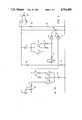
- FIG. 4is a schematic circuit diagram of the main control unit responsive to the wall control signals to control operation of the fan and light;
- FIG. 5Ais a waveform diagram illustrating two representative control signals impressed on the typical AC voltage curve
- FIGS. 5B to 5Kshow the pulse outputs at various points in the detector part of the circuit of FIG. 4 with a signal input as in FIG. 5A;
- FIGS. 6A and 6Bshow a program flow chart illustrating operational steps performed by the microprocessor of the main control unit of FIG. 4.
- FIG. 1illustrates a preferred embodiment of an electrical appliance control system according to the present invention.
- the system in the preferred embodimentis designed to control a combination ceiling fan 10 and light 12, generally provided in a combined ceiling fixture (not shown) to replace the standard ceiling light fixture, by means of a main control unit 14 operated from a remote wall control switching unit 16 which replaces the standard lighting fixture on/off switch and which is connected on one side of the standard household AC power line from a 120 Volt AC mains power supply input generally indicated at 18.
- the systemcontrols a ceiling fan and light combination, it could clearly be arranged to operate other types of electrical appliances in a similar manner in alternative embodiments, and more than two appliances could be controlled at the same time if desired.
- the wall control unit 16provides output control signals on output line 19 for detection by the main control unit 14 which controls operation the ceiling fan and light assembly.
- the main control unit 14is suitably provided in a housing (not shown) at the overhead ceiling fan/light fixture.
- the wall control unit 16comprises a signalling or signal generating circuit shown in more detail in FIG. 2 which has several normally open switches which are controlled from an external wall control panel having a series of manually operable push keys or devices to allow the operator to choose from a variety of different operations.
- the preferred arrangement of the control keysis illustrated in FIG. 1, and preferably comprises a series of two-way toggle keys or devices including on/off light control keys 22, 23; on/off fan control keys 24, 25 and reverse/program control keys 26, 27, the use of which is described in more detail below in connection with FIG. 6.
- Also included on the wall panelis an on/off power switch or button 28.
- the wall control unitis designed to transmit a variety of different control signals to the main control unit 16 in response to actuation of the various keys on the control panel, one distinctive control signal being produced by actuation of each key.
- the various components of the main control unitare powered by internal power supply 29 and include a detector assembly 30 for detecting the various control signals, and a microprocessor or microcomputer 32 operated in response to command signals from the detector assembly to control operation of a fan motor 34 and a lamp driver 36 connected to the fan 10 and light 12, respectively.
- the microprocessoroperates in response to stored program instructions associated with the various control signals, as described in more detail below, and is connected to the motor 34 through a motor driver 40 and resistor array 42 for controlling the speed of the fan.
- the microprocessoris also connected to a reversing relay 38 for controlling the direction of the motor, and thus the fan direction.
- the microprocessoris also connected to an audio driver 44 and speaker 46 for transmitting audio signals to the user as described below.
- All the components of the main control unit described abovemay be suitably mounted on a printed circuit board housed in the fan motor housing (not shown).
- the wall control unit 16will now be described in more detail with reference to FIG. 2. It is connected in series with the electrical appliance or load in the same manner as a conventional light switch.
- the unitis in two parts, one part of the positive phase of the AC waveform and one part for the negative phase of the AC waveform.
- Each part of the circuitbasically comprises a switching assembly which actually turns the main AC current on and off for a predetermined time interval according to which of the manual control keys is actuated.
- the switching assembliesbasically comprises a pair of oppositely connected switching devices 50 and 52, one for the positive half of each AC cycle and one for the negative half of each cycle.
- the switching devices 50 and 52each comprise silicon controlled rectifier (SCR) type thyristors. Operation of each of the thyristors is controlled by a respective switching circuit including three normally open switches 54, 56, 58 and 60, 62, 64 respectively, closure of which is controlled by depression of a selected side of the one of the two way keys of the wall control panel, as described below.
- SCRsilicon controlled rectifier
- the positive part of the circuit controlling thyristor 50will first be described. It will be understood that the negative part of the circuit operates in an equivalent manner.
- the gate current of thyristor 50is controlled by a precision firing circuit consisting of silicon bilateral switch 66 which has a specific breakover voltage, or voltage differential, at which it will go into conduction or "fire".
- a silicon bilateral switch 78having a specific breakover voltage controls firing of thyristor 52, and the three switches 60, 62 and 64 introduce successive precise firing delays into this circuit by means of time delay or charging circuits including capacitor 80 and the resistance introduced by closure of the specific switch.
- resistances 82 and 84are chosen, and the circuit calibrated, such that closure of switches 60, 62 or 64 respectively, introduces precise 30 degree, 45 degree and 60 degree firing delays in the negative half of the AC waveform. This is illustrated by the vertical lines in the lower half of the waveform shown in FIG. 3.
- a 45 degree delay closure of switch 62for example, will produce in the negative half of the cycle which will follow points D, E, F and G on the lower part of FIG. 4.
- a Zener diode 86, 88, respectively, and a resistor 90, 92, respectively,are arranged to form a simple regulator to assure a constant voltage source for the respective timing circuit. This reduces or eliminates effects from line voltage variations.
- the resistor 94 and capacitor 96 connected across the switching circuitcomprise a snubber circuit to prevent transient triggering of the silicon controlled rectifiers (SCR's) 50 and 52.
- the wall control circuitallows communication of six different control signals to the main control unit, each comprising different precise firing delays following the positive or negative going crossover (A or D in FIG. 3) of the AC waveform.
- Thisallows six different keys to be provided on the wall panel for operation by a user according to the precise function desired.
- the keysare provided in pairs as over center toggle devices, one of each pair controlling one of the positive cycle half switches and the other controlling the corresponding time delay one of the negative cycle half switches.
- the upper toggle switch or keys 22, 23are arranged to close switches 54 and 60, respectively, when depressed, and therefore comprise an on/off switch for the light.
- the 30 degree firing delay signal in the positive half of the waveformis used to control switching on of the lights, while the 30 degree firing delay signal on the negative half of the waveform is used to switch off the lights, as will be described in more detail below.
- toggle keys or devices 24, 25is used to selectively close switches 56 and 62, respectively, and thus to introduce a 45 degree firing delay signal on either the positive or negative half of the AC waveform.
- toggle keys 26, 27, respectivelyclose switches 58 and 64 when depressed to introduce a 60 degree firing delay signal on either the positive or negative half of the AC waveform.
- Each of the switchesis arranged to open automatically as soon as the corresponding toggle key is released.
- thyristors 50 and 52were part number S4006LS3 SCRs, 6 Amp/400 V, produced by Teccor Electronics, Inc. of Euless, Tex.
- Bilateral switches 66 and 78were each part number MBS4991 sold by Motorola Semiconductor Corporation.
- Resistors 68 and 69were each 5K ohm single turn cermet potentiometers, set at 2K Ohm, and resistors 70 and 71 each had values of 5.62K Ohm.
- Resistors 74 and 82each had values of approximately 4.02K Ohm, and resistors 76 and 84 had values of 6.19K Ohm.
- Resistors 70, 71, 74, 76, 82 and 84were all 1% metal film resistors.
- Capacitors 72 and 80were each 0.47 microfarad capacitors, and were of 5%/25 V metal film mylar, while capacitor 96 was a 0.1 microfared capacitor of 20%/250 V Mylar or equivalent.
- Zener diodes 86 and 92were the commonly available 1N5245 type.
- Resistors 90 and 92were 6.2K Ohm 5% carbon film resistors, and resistor 94 was 120 Ohms 5% Carbon film. Metal film resistors were chosen for temperature stability.
- Power switch 28may suitably be a 4 Amp/125 VAC slide switch, or equivalent, and switches 54 to 64 inclusive are PCB dome switches or snap-disc switches in the preferred embodiment, situated under the respective corresponding two way control keys on the external control panel.
- switches 54 to 64 inclusiveare PCB dome switches or snap-disc switches in the preferred embodiment, situated under the respective corresponding two way control keys on the external control panel.
- each of the pairs of control keyscomprises a two way pivot member which can be pushed in at either end to depress and close an underlying dome switch on the wall control unit printed circuit board, and the dome switches are biassed to open once the pivot member or control key is released.
- the detector assembly 30incorporates a precision digital timing circuit which watches the input voltage waveform on line 19 from the wall control unit 16 and which determines the zero crossing point of the waveform, the phase of the waveform (positive or negative), and the magnitude of the phase firing delay, which may be 0, 30, 45 or 60 degrees.
- the detector circuitconsists of two parts, one of which is responsive to the positive part of the input on line 19 and the other of which is responsive to the negative part of the input.
- the positive partconsists of a series of two inverters 104 and 106 and an OR gate 108, the output of which is connected to the RESET port of a first flip-flop 100.
- the negative partconsists of an inverter 110 and an OR gate 112 connected to the RESET port of a second flip-flop 102.
- the outputs of inverter 104 and 110are connected through a further OR gate 114 to the clock inputs of the two flip flops.
- a phase control signalis provided on line 122 from the output of inverter 106.
- the Q outputs of flip-flops 100 and 102are connected to the two inputs of OR gate 124, and the output of OR gate 124 is connected to an inverter 126 to provide a data control signal on line 128.
- a zero crossing output control signalis provided on line 116 from OR gate 124 through one-shot 118 and inverter 120.
- Inverters 104, 106, 110, 118, 120 and 126are provided by Hex Schmidt inverter part number CD4584 which is available from various manufacturers.
- OR gates 108, 112, 114 and 124are provided by a single Quad Exclusive OR gate part number CD4070 produced by various manufacturers.
- Flip-flops 100 and 102are also provided by a single chip device, Dual D flip-flop part number CD4013 produced by various manufacturers.
- Other components of the detector circuit in the preferred embodimentinclude input resistors 130, 132, each preferably of 100K Ohm, resistors 134, 136 of 1K Ohm, resistor 138 (10K Ohm), resistor 140 (56K Ohm), and resistor 142 (100K Ohm).
- OR gates 108 and 112each have a resistor 143 and capacitor 144 connected to their inputs as shown in FIG. 4, and these have preferred values of 100K Ohm and 0.01 microfarads, respectively.
- a capacitor 146suitably of 0.01 microfarads is connected in the output line between one-shot 118 and inverter 120.
- FIGS. 5A to 5Kwhere a representative input AC waveform from the wall control unit is shown in FIG. 5A and the other pulsed signals represent outputs at various points in the detector circuit marked as TP 1 to TP 10, inclusive, on FIG. 4 as a result of such an input signal.
- the input control signal waveform of FIG. 5Ashows a standard AC waveform for the first cycle, followed by a 30 degree firing delay 150 in the positive half of the AC waveform (produced by closing switch 54), then another standard waveform cycle followed by a 60 degree firing delay 152 in the negative half of the cycle (produced by closing switch 64).
- FIG. 5Bshows the output of inverter 104 at point TP1. This portion of the circuit looks only at the positive half of the AC waveform.
- the inverter 104turns off when the rising waveform reaches approximately 10 volts, which normally happens quickly after a standard positive going zero crossing. However, when the rise in the waveform after a zero crossing is delayed by the wall control unit, as indicated at 150 in FIG. 5A, turn off of inverter 104 will also be delayed, as can be seen by lengthened pulse 154 in FIG. 5B.
- the inverterturns on again when the descending waveform reaches approximately 10 volts, just before the next zero crossing.
- inverter 106simply inverts the output of inverter 104, and supplies this information on line 122 to a phase control input 156 of the microprocessor or microcomputer 32.
- the microcomputeris programmed to look at the information at input 156 only approximately 7 milliseconds after each zero crossing.
- FIG. 5Cshows the output of inverter 110 at point TP2, which is in the portion of the circuit looking at only the negative half of the AC waveform.
- the inverter 110turns off when the rising waveform reaches -10 V (just before positive going zero crossing) and turns on again when the descending waveform reaches approximately -10 V (just after the negative going zero crossing).
- the point at which the inverter 110 turns oncan be delayed by actuation of switches 60, 62 or 64, and a representative 60 degree shortened pulse 158 produced by closure of switch 64 to produce firing delay 152 is shown in FIG. 5C.
- switches 54, 56 and 58will produce shortened positive pulses at the output of inverter 106, and closure of switches 60, 62 and 64 will produce shortened pulses at the output of inverter 11, with the length of the shortened pulse being dependent on which switch is closed.
- FIG. 5Dshows the output of OR gate 114, whose inputs are the outputs of inverters 104 and 110, respectively as shown in FIGS. 5B and 5C. This leads to a pulse that is present at every zero crossing and whose duration contains the signalling information. This signal is used to clock the two flip-flops as indicated in FIG. 4.
- FIGS. 5E and 5Fare the outputs of gates 108 and 112 at points TP4 and TP5, respectively.
- Gates 108 and 112are used as simple edge detectors to produce a pulse at the edge of each input pulse.
- the time constant of the resistor/capacitor network 143, 144 on the input of each of these gatesprovides a relatively long reset pulse (over one millisecond) to the reset ports of the two flip-flops.
- FIGS. 5G and 5Hshow the output signals from flip-flop 100 and 102, respectively, which are recombined in OR gate 124 to provide the signal shown in FIG. 5I.
- This signalis inverted by inverter 126 to provide the data control signal shown in FIG. 5J on line 128 which is connected to a control input 160 of the microprocessor.
- This signalis combined with the phase control signal input by the computer to determine which of the six control keys has been depressed, as explained in more detail below.
- OR gate 124is also connected through one shots 118 and 120 to provide the signal shown in FIG. 5K online 116, which is provided to an input 159 of the microprocessor as a zero crossing control signal.
- Inverters 118 and 120are used as one shots to create a final, fixed width zero cross pulse for the microprocessor, which provides the necessary timing function for detecting the presence of control signals from the wall control unit, for other internal microcomputer operations, and for output related functions as discussed in more detail below.
- the input to inverter 118may alternatively be taken from OR gate 114, but the arrangement shown in FIG. 4 provides a more accurate zero cross signal.
- the input waveform shown in FIG. 5Ashows a "kick" in the waveform after zero crossing whenever the flow of current is interrupted by a signalling event as the result of closure of one of the wall control switches. This is due to the back emf from the highly inductive AC motor used in the system.
- the "kick”is carried to the output of gate 114 (FIG. 5D) and attempts to clock the flip flops.
- the "kick”can have no effect since the flip flop can only be reset by a pulse into the reset port from OR gate 112 (FIG. 5F). This occurs only when the pulse from the edge detector arrives, and this is in synchronization with the firing of the SCR 52 at the 60 degree firing angle.
- OR gate 112FIG. 5F
- the microcomputer 32is pre-programmed to process the control data by determining the time width of the data pulse at input 160 on each half cycle. It determines which of four pulse width windows (corresponding to 0, 30, 45 and 60 degree firing delays) the data pulse fits, then looks for the signal to be repeated.
- the microcomputer programrequires any signal corresponding to firing delays other than 0 degrees to be present for a total of 12 consecutive cycles before declaring it to be valid and executing the corresponding commands. The microcomputer operation is described in more detail below with reference to the flow diagram of FIG. 6.
- Control outputs from the microcomputerare connected on line 162 to the lamp driver 36, and on lines 164, 166 to the audio driver 44.
- Output lines 168, 170are connected to reversing relay 38, and input line 172 from the reversing relay enables the microcomputer to determine the current status of that relay and thus determine whether the fan airflow direction is up or down and to determine which of two relay coils 174, 176 must be energized whenever reversing is called for.
- a series of motor speed control outputs 178are provided from the microcomputer. Each speed control output 178 is connected to the motor driver 40, which as shown in FIG. 4 comprises a series of motor control triacs 180 each of which has an input connected through resistor 182 to a respective one of the speed control outputs 178.
- the motor control triacseach have outputs connected to successive taps in resistor array 42 to introduce selected resistances in series with the motor to control its speed.
- the first triacis connected directly to the motor, and the next five triacs are connected to a series of successive taps between resistors 184, 186, 188, 190 and 192 in the array.
- the motor control triacspreferably have low DVDT sensitivity and in a preferred embodiment of the invention six different speed control outputs 178 were provided, corresponding to speeds 1 to 6 inclusive. Clearly a greater or lesser number of possible speeds may be provided if desired. Based on the expected motor loads at the specified speeds, TO 92-sized triacs may be used for the lower speed settings 1 to 3 while a TO 220-size is needed for speeds 4 to 6.
- the top two motor control triacs of FIG. 4may be part number L401E5 produces by Teccor, or equivalents, and the other four motor control triacs may suitably be part number L4004F51, also produced by Teccor, or equivalents.
- a low DVDT sensitivity motor control triacis desirable to prevent unwanted, temporary motor operation during signalling for light operation.
- Resistors 182each comprise 1.2K Ohm resistors.
- the motor speedis controlled by electronic selection of the taps within resistor array 42 connected in series between the triacs 180 and the motor 34.
- the resistor array 42is preferably in the form of a flexible printed resistor pattern of wires bonded to silicon rubber and valcanized, although other types of resistor array may be used.
- the lead wire materialmay be Telfon or Mylar flat cable.
- the series of resistors in the array 184, 186, 188, 190 and 192have values 50 Ohms, 54 Ohms, 66 Ohms, 105 Ohms and 175 Ohms, respectively in one embodiment. However, different resistance valves may be used if different speed settings are desired.
- the six fan speeds produced by introduction of successive resistors into the series in the preferred embodimentare as follows:
- a flexible resistor arrayto control the fan motor speed provides a substantially pure sine wave to the motor at any speed, assuring relatively silent operation through speed changes. Another advantage is that the zero crossing point information is preserved.
- a circuitous patternis provided in the array to spread heat dissipation out over as large a surface as possible to minimize hot spots, and the array may be mounted on the motor housing or dissipating heat.
- the light driver 36is a conventional light dimmer control circuit comprising a triac-type phase control.
- Light control triac 194has its gate connected to the lighting control output 162 from microcomputer 32 through transistor amplifier 196 and resistor 197, and inductor 198 is connected between the triac and lamp. Connected across the triac and inductor 198 is capacitor 199.
- the microprocessoris programmed to provide a desired ramp rate for the light by producing an output pulse on line 186 at prdetermined intervals after zero crossing to trigger the triac at a suitable phase between a lowest intensity or power setting to a highest intensity setting. In the preferred embodiment the light can be ramped in 16 steps between the lowest intensity and the highest intensity setting in 5 seconds, or vice versa.
- Triac 194is suitably a 5 amp rated triac with low DVDT sensitivity and is provided with an ample heat sink to handle the maximum lighting load, which may be of the order of 340 watts.
- the light control triacwas a part number L4006L manufactured by Teccor.
- Transistor 196was part number 2N3904 produced by various manufacturers. Resistor 197 had a value of 100 Ohms, inductor 198 was a 120 UH, 4 Amp bar configuration inductor, and capacitor 199 had a value of 0.047 microfarads. Resistor 196 had a value of 5.1K Ohm.
- the power supply 29is a basic voltage regulator circuit utilizing resistive network 200 to reduce the input voltage to 10 VAC and voltage regulator 201 to tightly control the supply at 5 VDC.
- the power supplyis capable of maintaining memory during brief power interruptions of less than 1 second.
- the specific components used in the power supply circuit in one examplewill now be given, although it will be understood that other, equivalent components may be used.
- the resistive network 200was a flexible resistor array with a first portion of 510 ohms and a second portion of 1500 ohms.
- the voltage regulator 201was part number LM7905 also available from various manufacturers, and capacitor 204 had a value 470 microfarads with capacitor 206 having a value of 10 microfarad.
- Diode 202was a part number IN4004, and diode 203 was a part number IN5930.
- the audio driver 44is designed to produce a two-tone signal at speaker 46, with the signal comprising an ascending two-tone chime on fan or light turn on, or fan speed increase, and a descending tow-tone chime on fan turn off or speed decrease.
- the tone frequenciesare chosen for general pleasantness to the hearer with the selected speaker, and preferably last no longer than a total of 0.5 seconds.
- the audio driver or frequency generatorcomprised timer 210, suitably part number LM5555CN or equivalent, produced by various manufacturers, connecting to high and low control inputs 164, 166, respectively, from the microprocessor through diodes 216, each of which may be part number 1N4148 or equivalent diodes, and resistors 218 and 220, respectively, having values of 1K and 10K, respectively.
- a control pulse on line 164produces a high tone frequency output
- a control pulse on line 166produces a low tone output from speaker 46.
- the control output from microprocessor 32determines whether an ascending or descending frequency audio signal is produced at speaker 46, as will be described in more detail below.
- audio driver circuit 44Also provided in audio driver circuit 44 are resistor 224 of 6.8K, capacitor 226 of 068 microfarads, and capacitors 228 and 230 each of 0.01 microfarads.
- the audio transducer or speaker 46is connected to the audio driver output through resistor 232 which is a 47 Ohm resistor.
- the microcomputer 32operation to provide the various control pulse outputs on lines 162, 164, 166, 168, 170 and 178 as generally described above will now be explained in more detail with reference to the flow diagram of FIG. 6.
- the microcomputeris programmed to detect the input command signals on lines 116, 122, and 128 from the detector circuit, to determine which of eight possible input codes is present at any one time, and to associate that specific code with a programmed sequence of events which are initiated whenever that code is validated.
- the eight possible codescorrespond to +0, +30, +45, +60, -0, -30, -45 and -60 degree phase delays, respectively.
- the programrequires any signal other than + or -0 to be present for a total of 12 consecutive cycles before carrying out the operation associated with that signal. This corresponds to an operator pushing down one side of one of the control keys for at least 0.1 seconds.
- the microcomputer used in one examplewas a Sanyo LM6413 microcomputer. However, it will be understood that other equivalent microcomputers may be used in alternative embodiments.
- the circuit 234is a standard microcomputer clock input circuit including an 800 KHz resonator 235, and this circuit will not be described in more detail since such circuits are well known in the field.
- the microcomputeris programmed to carry out the steps listed generally in FIGS. 6a and 6b described in more detail below.
- the microcomputerWhen power is initially switched on (300), or following power interruptions of more than 1 second, the microcomputer resets and initializes (302) with the following status (303):
- Reversing relay statusis checked on line 172 controlled on lines 168, 170 into an airflow downward status (i.e. fan direction to blow air downwards for cooling airflow effects).
- Light intensityis controlled on line 162 to be high.
- the microcomputerthen continually monitors the control signal inputs on lines 116, 122 and 128 for anything other than a 0 degree phase delay on the positive or negative half of each cycle (step 304, 306). If any non-zero signal is present for at least 12 consecutive cycles (308), the micrcomputer determines the phase (310) and length of the delay according to the length of the input data pulse. If a positive delay of 30 degrees is detected (314), which lasts for less than 1.0 seconds, the lights are turned on at the previous intensity, (316) as stored in the microcomputer memory. If an operator wishes to ramp up the light intensity, the switch 54 is depressed via control key 22 for longer than 1.0 seconds.
- the microcomputer (315)which ramps the light intensity upwards in equal steps (318) until the switch is released, which is detected by a 0 degree pulse length signal on data control line 128.
- the light intensitycan be set as desired by pushing button or key 22 and releasing it when the desired level is reached.
- the light intensityis ramped as described above by triggering light drive triac 194 at increasing voltage levels.
- the microcomputeris programmed to turn the lights on gradually, i.e. when a lights on input signal is received, the microcomputer slowly ramps the light power on control line 162 from low to full-on or previous intensity in a predetermined time period, for example of the order of 1.5 seconds. This slow turn on extends light bulb life by minimizing or reducing the shock of turn on, and also reduces eye strain of the user.
- the microcomputerturns the lights off (332).
- the lights off stepis a delayed procedure in which the light intensity is reduced gradually to zero, to give the user time to move to another room before the lights actually turn off.
- the programreduces the light intensity immediately by about 25% when the light off button is first pushed, then after about 12 seconds begins ramping the light intensity downward to low intensity, then turns the lights off. If the lights OFF button is pushed a second time during this period, the light is turned off immediately.
- the microcomputeris programmed to ramp the light intensity downward (336) until the 0 degree signal is again detected, indicating that the user has released the button. This allows the user to reduce the light intensity as desired.
- the microcomputeris programmed to store any selected light intensity in its memory for subsequent operations of the lights until an operator again alters the intensity.
- the +45 degree signal 337is associated by the computer with a command to turn on the fan. If it is present for less than 1.0 seconds, indicating only a quick push and release of fan ON button 24, the fan is turned ON at the previously stored fan speed along the appropriate one of the control lines 178 energizing the appropriate motor driver triac 180 to introduce the corresponding resistance into the motor circuit and thus switch on the fan motor at the appropriate speed. If the fan ON signal is present for over 1.0 seconds (338), the fan speed is ramped upwards (340) by energizing successive triacs in the motor driver to decrease the resistance and increase the speed setting until a 0 degree control signal is again detected, indicating the fan ON button has been released. Thus the user can set the fan speed by releasing the ON button at the desired level. Any speed set in this way will be stored in the microcomputer memory for subsequent operations.
- a -45 degree signal 342is detected for less than 1.0 seconds, the fan is turned OFF (343). If the signal is present for over 1.0 seconds (344), indicating the user has pushed and held down the fan OFF button 25, the fan speed is ramped downwards (345) through the speed settings by energizing successive triacs in the motor driver to increase the resistance in the motor circuit until 0 degree signal is again detected. This allows the user to reduce the fan speed until a desired lower level is reached by releasing the OFF button at the desired level.
- the upward and downward ramp rate for the fanis preferably such that it can be ramped from speed 1 to speed 6 in 9 seconds or vice versa.
- full poweris applied at each step for 0.5 seconds in order to minimize lag between the speed called for and the actual speed of the fan.
- all power to the motoris turned off and the fan is allowed to coast until power is reapplied at the selected speed.
- the +45 and -45 degree signalsalso initiate operation of the audio driver in the following manner.
- the microcomputercontrols the audio driver on lines 166, 164 to emit a quick ascending two tone chime sequence to confirm reception of the command.
- a speed decrease step or fan turn off command(342)
- a quick, descending two tone chimeis sounded. These are sounded at each speed increase or decrease step, respectively.
- the -60 degree signal 350is associated with a fan reversal command initiated by the user pushing REVERSE button or key 26. On detection of this signal, a reverse fan sequence 352 is initiated which consists of the following steps:
- a two tone descending audio signalis sounded by control on lines 164, 166 to indicate reception of the command.
- the reversing relayis switched to the opposite direction after approximately 0.2 seconds delay.
- Poweris reapplied to the motor by energizing the appropriate motor triac/80 approximately 0.4 seconds after step 3. If the preset motor speed is 3 or slower, the preset power level is applied directly. If the preset speed is 4 or higher, power is reapplied first at speed 3 for one second before increasing to the pre-set level.
- This sequencewhich enables the reversing relay to be switched "dry", i.e. when no current is being conducted through the contacts, assures relatively long contract life, eliminates or reduces the possibility of electrical transients which could otherwise cause the microcomputer memory to be scrambled, and allows the use of a low cost relay.
- the +60 degree signal 360is associated in the computer program with a series of special programs. The program selected depends on the duration of the +60 degree signal, i.e. how long the user depresses PROGRAM button or key 27 before releasing it.
- the +60 degree sequence of stepsis as follows:
- any number of alternative special programsmay be provided in a similar fashion by suitably programming the microcomputer.
- the special programs referred to abovewhich are provided in one embodiment of the present invention will now be described in more detail.
- the desired programis selected by the user by depressing the PROGRAM button until a corresponding number of audio signals are heard, i.e. one signal for COMFORT, two for SECURITY, and so on, and then releasing the button.
- Only one programmay be selected and engaged at any one time, and the selected program may be cancelled either by turning the power switch off for three sounds or by holding the REVERSE side of the REVERSE/PROGRAM key down until an audio signal is heard indicating cancellation.
- the COMFORT programis a fan speed reducing program which may be utilized at night, for example, to reduce the fan speed gradually according to the reduced need for cooling that would be encountered in a bedroom, for example.
- This programcauses the fan speed to reduce by one setting after 1.5 hours of running time following initiation of the program. 2.5 hours later the speed is reduced one more setting.
- the speedmay be altered manually by the fan OFF and ON buttons during running of the programs, but the timing of events remains unaltered. While the program is in operation, the light, fan and reverse/program control panel buttons remain effective.
- the programis self-cancelling after one cycle, requiring resetting by the user every night if required.
- the SECURITY programprovides on and off control of the lighting to give the impression of an occupied home.
- the programfollows the following sequence:
- the LIGHT REMINDER programwill turn the lights off automatically 90 minutes after each time they are turned on by the user. It is announced by three audible signals. At the end of the 90 minute period, the lights are dropped to half intensity for 30 seconds, then turned off. This is to give a warning to any occupant of the room.
- This programis designed for use in rooms that are typically not lit for extended periods of time and where lights are often left on inadvertently. When this program is in operation, the control panel keys all remain effective. The user may alter the light intensity setting, but the lights will still be turned off after the designated time period unless the ON/OFF key is operated to turns the lights off and back on again.
- the demonstration programis intended for use in demonstrating the flexibility of the system or testing its operation.
- a pre-programmed sequence of light and an eventsis carried out, including ramping up and down of the fan speed and light intensity, and reversing of the fan.
- the control system of this inventiontherefore allows two or more electrical appliances to be controlled independently from a plurality of wall switches without requiring any requiring of a standard household electrical circuit. This is done by detection circuitry which can distinguish precise time events after each zero crossing, so that a plurality of control signals comprising predetermined length signal delays after positive or negative going zero crossings can be provided, each initiated by actuation of a different wall switch or control button. In this way the back emf kick from the fan motor will be ignored by the detection circuit.
- the + and -30 degree phase delay signalsare associated with lighting control by appropriate programming of the microcomputer. This provides a solid, easily detected signal that is on the fringe of the back emf "kick" of the fan motor, and produces the least reduction in available power. It is therefore preferably used for control of the lights, so that the light intensity will not be dimmed appreciably by depression of the light ON/off key.
- the 45 degree firing delay signalreduces the available power slightly more, and is used in the preferred embodiment for the fan ON/OFF and fan speed DOWN/UP signals.
- the 60 degree signalgives the greatest reduction in power to the main controller, and is capable of generating objectionable motor noise. For this reason the fan motor is preferably turned off during these signals. Their may be some noticeable dimming of the lights during the 60 degree signalling, but the user will recognize this as an indication of proper signalling and full intensity will be restored when the appropriate control button is released.
- the last light intensity and speed settingsare memorized by the microcomputer when these appliances are turned OFF at the appropriate OFF control buttons, and they are automatically returned to the previous settings when turned ON again.
- This control systemallows for increased flexibility and easy operation by providing a plurality of different control signals each initiated by the user on depressing a signal control button or key.
- the userdoes not have to memorize various multi-key sequences for alternative operations, but can turn the lights or fan on or off, increase or decrease the fan speed or light intensity, reverse the fan or select any one of a series of programs, all by means of a single pushbutton or switch operation.
- the systemdoes not rely on detecting critical analog voltage levels, which may vary and give rise to errors, but involves only the timing of events following each zero crossing of the AC line voltage. Because the precision digital timing or detector circuit can tolerate phase shifting, a transformer based power supply may be used.
- the wall control firing circuit of FIG. 2includes a highly stable power regulator for maintaining precise firing angles over wide variations in line voltage or fan load.
- the electronic circuitry of the control systemis relatively simple, inexpensive and reliable.
- the systemcan easily be expanded to provide additional program sequences simply by reprogramming the microprocessor. Since the wall control unit is polarized, it must be initially be installed the right way round for correct operation, although no damage can be caused by reverse installation.
- the microprocessormay be provided with a device for detecting the installation polarity in alternative embodiments.
- the systemmay be used to operate a fan which is not equipped with lights. In this case the light switch will simply be ineffective. It may alternatively be used to operate other or additional electrical appliances by suitable modification of the wall control unit to provide additional delay signals.
Landscapes
- Physics & Mathematics (AREA)
- General Physics & Mathematics (AREA)
- Engineering & Computer Science (AREA)
- Automation & Control Theory (AREA)
- Control Of Ac Motors In General (AREA)
Abstract
Description
______________________________________ Speed setting RPM Approx. Res. ______________________________________ 6 200 0 5 140 55 Ohms 4 100 100 3 75 190 2 50 350 1 25 700 ______________________________________
Claims (30)
Priority Applications (1)
| Application Number | Priority Date | Filing Date | Title |
|---|---|---|---|
| US06/886,249US4716409A (en) | 1986-07-16 | 1986-07-16 | Electrical appliance control system |
Applications Claiming Priority (1)
| Application Number | Priority Date | Filing Date | Title |
|---|---|---|---|
| US06/886,249US4716409A (en) | 1986-07-16 | 1986-07-16 | Electrical appliance control system |
Publications (1)
| Publication Number | Publication Date |
|---|---|
| US4716409Atrue US4716409A (en) | 1987-12-29 |
Family
ID=25388702
Family Applications (1)
| Application Number | Title | Priority Date | Filing Date |
|---|---|---|---|
| US06/886,249Expired - LifetimeUS4716409A (en) | 1986-07-16 | 1986-07-16 | Electrical appliance control system |
Country Status (1)
| Country | Link |
|---|---|
| US (1) | US4716409A (en) |
Cited By (83)
| Publication number | Priority date | Publication date | Assignee | Title |
|---|---|---|---|---|
| US4990908A (en)* | 1989-03-23 | 1991-02-05 | Michael Tung | Remote power control for dual loads |
| US5041825A (en)* | 1989-11-03 | 1991-08-20 | Casablanca Industries, Inc. | Remote control system for combined ceiling fan and light fixture |
| US5164644A (en)* | 1991-10-07 | 1992-11-17 | Frank Hsieh | Apparatus for controlling a ceiling fan |
| WO1993001575A1 (en)* | 1991-07-12 | 1993-01-21 | Trade Winds Fan Company, Inc. | Appliance control system and method |
| US5189412A (en)* | 1990-05-11 | 1993-02-23 | Hunter Fan Company | Remote control for a ceiling fan |
| US5287287A (en)* | 1990-09-14 | 1994-02-15 | Energy Audit Corporation | Power consumption rate display device |
| US5340277A (en)* | 1993-05-03 | 1994-08-23 | The Genie Company | Controller for remote control ceiling fan |
| US5424587A (en)* | 1992-09-08 | 1995-06-13 | Federowicz; John S. | Integrated electrical/communication system hardware |
| US5488273A (en)* | 1994-11-18 | 1996-01-30 | Chang; Chin-Hsiung | Ceiling fan and light assembly control method and the control circuit therefor |
| US5511943A (en)* | 1994-11-09 | 1996-04-30 | Chang; Chin-Hsiung | Single-throw switch circuit controlling a ceiling fan and light assembly |
| US5541584A (en)* | 1992-05-15 | 1996-07-30 | Hunter Fan Company | Remote control for a ceiling fan |
| US5559406A (en)* | 1994-11-18 | 1996-09-24 | Chang; Chin-Hsiung | Ceiling fan and light assembly control circuit with remote controller/single-throw switch optional controls |
| US5559395A (en)* | 1995-03-31 | 1996-09-24 | Philips Electronics North America Corporation | Electronic ballast with interface circuitry for phase angle dimming control |
| US5572104A (en)* | 1992-05-20 | 1996-11-05 | Texas Instruments Incorporated | Furnace control apparatus |
| US5586867A (en)* | 1994-01-19 | 1996-12-24 | Mehlos; Michael D. | Direct mounted fan apparatus |
| US5604411A (en)* | 1995-03-31 | 1997-02-18 | Philips Electronics North America Corporation | Electronic ballast having a triac dimming filter with preconditioner offset control |
| US5689261A (en)* | 1994-07-12 | 1997-11-18 | Hunter Fan Company | Remote control system for ceiling fan and light |
| US5738496A (en)* | 1996-12-23 | 1998-04-14 | Hunter Fan Company | Interchangeable plug-in circuit completion modules for varying the electrical circuitry of a ceiling fan |
| US5815219A (en)* | 1993-12-22 | 1998-09-29 | Matsushita Electric Industrial Co., Ltd. | Large screen video display system and television receiver |
| US5864186A (en)* | 1998-03-20 | 1999-01-26 | Cts Corporation | Slide actuated audio volume control assembly |
| US5982110A (en)* | 1997-04-10 | 1999-11-09 | Philips Electronics North America Corporation | Compact fluorescent lamp with overcurrent protection |
| US5996898A (en)* | 1998-04-07 | 1999-12-07 | University Of Central Florida | Automatic occupancy and temperature control for ceiling fan operation |
| US6011357A (en)* | 1997-04-10 | 2000-01-04 | Philips Electronics North America Corporation | Triac dimmable compact fluorescent lamp with low power factor |
| US6043611A (en)* | 1997-04-10 | 2000-03-28 | Philips Electronics North America Corporation | Dimmable compact fluorescent lamp |
| US6078159A (en)* | 1999-02-17 | 2000-06-20 | The Chamberlain Group, Inc. | Method and apparatus for programming a logic board from switching power |
| US6120262A (en)* | 1998-10-07 | 2000-09-19 | Emerson Electric Co. | Electronic device control system |
| US6399672B1 (en) | 1999-06-02 | 2002-06-04 | Sartomer Technologies Co., Inc. | Oil soluble metal-containing compounds, compositions and methods |
| US6702664B1 (en)* | 2001-10-16 | 2004-03-09 | Steven R. Coven | Portable fume exhauster-carpet and floor dryer |
| US20040238637A1 (en)* | 2000-04-18 | 2004-12-02 | Metrologic Instruments, Inc. | Point of sale (POS) based bar code reading and cash register systems with integrated internet-enabled customer-kiosk terminals |
| US6906617B1 (en)* | 2000-11-17 | 2005-06-14 | Koninklijke Philips Electronics N.V. | Intelligent appliance home network |
| US6930260B2 (en) | 2001-02-28 | 2005-08-16 | Vip Investments Ltd. | Switch matrix |
| US20060012928A1 (en)* | 2002-07-25 | 2006-01-19 | Helmut Theiler | Circuit arrangement for controlling two independent load resistors that can be operated with a rectifield alternating current voltage |
| US7043380B2 (en) | 2003-09-16 | 2006-05-09 | Rodenberg Iii Ernest Adolph | Programmable electricity consumption monitoring system and method |
| US7069091B2 (en) | 2001-11-01 | 2006-06-27 | Salton, Inc. | Intelligent microwave oven appliance |
| US20060273751A1 (en)* | 2005-06-06 | 2006-12-07 | Lutron Electronics Co., Ltd. | Method and apparatus for quiet variable motor speed control |
| US7151968B2 (en) | 2001-11-01 | 2006-12-19 | Salton, Inc. | Intelligent coffeemaker appliance |
| US20070110192A1 (en)* | 2005-06-06 | 2007-05-17 | Steiner James P | Method of communicating between control devices of a load control system |
| US7307542B1 (en) | 2003-09-03 | 2007-12-11 | Vantage Controls, Inc. | System and method for commissioning addressable lighting systems |
| US7394451B1 (en) | 2003-09-03 | 2008-07-01 | Vantage Controls, Inc. | Backlit display with motion sensor |
| US20080198917A1 (en)* | 2007-02-16 | 2008-08-21 | Ark-Les Corporation | Pulse-based communication for devices connected to a bus |
| US20080252430A1 (en)* | 2004-04-22 | 2008-10-16 | Lester Marshall E | Powerline pulse position modulated transmitter apparatus and method |
| US20090027824A1 (en)* | 2003-09-03 | 2009-01-29 | Vantage Controls, Inc. | Current Zero Cross Switching Relay Module Using A Voltage Monitor |
| US7489094B2 (en) | 2005-11-18 | 2009-02-10 | Lutron Electronics Co., Inc. | Method and apparatus for quiet fan speed control |
| US7520444B1 (en)* | 2002-01-15 | 2009-04-21 | At&T Intellectual Property I, L.P. | System and method for controlling heat exchanger fans |
| US20090224612A1 (en)* | 2008-03-05 | 2009-09-10 | Gallen Ka Leung Tsui | Low Power Switching Circuit |
| US20090267806A1 (en)* | 2006-09-19 | 2009-10-29 | Juergen Blank | Electrical Circuit |
| US20100007291A1 (en)* | 2008-07-10 | 2010-01-14 | Ming-Hui Lin | Current-limiting protection circuit of a remotely controlled ceiling fan-lamp |
| US20100013649A1 (en)* | 2006-06-20 | 2010-01-21 | Spira Joel S | Load control device having audible feedback |
| US20100072903A1 (en)* | 2008-09-25 | 2010-03-25 | Microsemi Corp. - Analog Mixed Signal Group Ltd. | Color and Intensity Control Over Power Wires |
| US7701078B1 (en) | 2007-08-06 | 2010-04-20 | The United States Of America As Represented By The Secretary Of The Air Force | Common bus aircraft retrofit load control |
| US20100109577A1 (en)* | 2008-11-05 | 2010-05-06 | Loughrey James F | Cascading addressable mastering protocol-based lighting system |
| US7755506B1 (en) | 2003-09-03 | 2010-07-13 | Legrand Home Systems, Inc. | Automation and theater control system |
| US7778262B2 (en) | 2005-09-07 | 2010-08-17 | Vantage Controls, Inc. | Radio frequency multiple protocol bridge |
| USRE41739E1 (en)* | 2000-09-06 | 2010-09-21 | Powerline Control Systems, Inc. | Synchronization/reference pulse-based powerline pulse position modulated communication system |
| US7861188B2 (en) | 2002-03-08 | 2010-12-28 | Revelation And Design, Inc | Electric device control apparatus and methods for making and using same |
| US20110074382A1 (en)* | 2009-09-25 | 2011-03-31 | University Of Washington | Whole structure contactless power consumption sensing |
| US8294556B2 (en) | 2007-04-17 | 2012-10-23 | Powerline Control Systems, Inc. | Powerline control system and method |
| US8421368B2 (en) | 2007-07-31 | 2013-04-16 | Lsi Industries, Inc. | Control of light intensity using pulses of a fixed duration and frequency |
| US20130096726A1 (en)* | 2011-10-15 | 2013-04-18 | Philip Scott Lyren | Home Appliance That Can Operate In A Time Range |
| US8604709B2 (en) | 2007-07-31 | 2013-12-10 | Lsi Industries, Inc. | Methods and systems for controlling electrical power to DC loads |
| US8763750B1 (en) | 2012-12-22 | 2014-07-01 | Homewerks Worldwide, LLC | Audio equipped fan |
| US8805628B2 (en) | 2009-09-25 | 2014-08-12 | Belkin International, Inc. | Systems and methods for measuring electrical power usage in a structure and systems and methods of calibrating the same |
| US8903577B2 (en) | 2009-10-30 | 2014-12-02 | Lsi Industries, Inc. | Traction system for electrically powered vehicles |
| US20140360805A1 (en)* | 2012-12-22 | 2014-12-11 | Homewerks Worldwide, LLC | Audio equipped fan |
| US8924604B2 (en) | 2011-09-26 | 2014-12-30 | Belkin International, Inc. | Systems and methods for data compression and feature extraction for the purpose of disaggregating loads on an electrical network |
| US9250275B2 (en) | 2007-09-18 | 2016-02-02 | Georgia Tech Research Corporation | Detecting actuation of electrical devices using electrical noise over a power line |
| WO2016025595A1 (en)* | 2014-08-12 | 2016-02-18 | Hunter Fan Company | Electronic ceiling fan control system and method of use |
| USD752202S1 (en) | 2013-08-08 | 2016-03-22 | Homewerks Worldwide, LLC | Fan grille |
| US9291694B2 (en) | 2010-07-02 | 2016-03-22 | Belkin International, Inc. | System and method for monitoring electrical power usage in an electrical power infrastructure of a building |
| US9344787B2 (en) | 2012-12-22 | 2016-05-17 | Homewerks Worldwide, LLC | Audio equipped fan |
| TWI567337B (en)* | 2014-12-11 | 2017-01-21 | 陳仕昀 | Intelligent control module,intelligent fan light,intelligent remote controller of the fan light and intelligent fan light control method |
| EP2045909A3 (en)* | 2007-10-02 | 2017-08-16 | Festool GmbH | Hand tool |
| US9766277B2 (en) | 2009-09-25 | 2017-09-19 | Belkin International, Inc. | Self-calibrating contactless power consumption sensing |
| USD808001S1 (en) | 2016-03-14 | 2018-01-16 | Homewerks Worldwide, LLC | Square fan grille |
| US10514399B1 (en) | 2017-08-08 | 2019-12-24 | II Donald P. Orofino | Measurement of alternating electric current via electromagnetic dynamic sensor measurements |
| USD932611S1 (en) | 2019-06-24 | 2021-10-05 | Homewerks Worldwide, LLC | Fan grille |
| USD932612S1 (en) | 2019-11-26 | 2021-10-05 | Homewerks Worldwide, LLC | Fan grille |
| USD933194S1 (en) | 2019-06-24 | 2021-10-12 | Homewerks Worldwide, LLC | Fan grille |
| USD933195S1 (en) | 2019-11-26 | 2021-10-12 | Homewerks Worldwide, LLC | Fan grille |
| USD933809S1 (en) | 2019-11-26 | 2021-10-19 | Homewerks Worldwide, LLC | Fan grille |
| USD948025S1 (en) | 2019-11-26 | 2022-04-05 | Homewerks Worldwide, LLC | Fan grille |
| CN114980428A (en)* | 2022-04-26 | 2022-08-30 | 欧普照明股份有限公司 | Fan lamp control circuit and fan lamp |
| US20230268853A1 (en)* | 2020-07-09 | 2023-08-24 | De'Longhi Appliances S.R.L. Con Unico Socio | Control method and circuit for a direct current motor for an infusion unit of a machine for preparing coffee beverages |
Citations (14)
| Publication number | Priority date | Publication date | Assignee | Title |
|---|---|---|---|---|
| US3896355A (en)* | 1974-06-13 | 1975-07-22 | Honeywell Inc | Self-powered thyristor trigger circuit |
| US4155015A (en)* | 1977-10-20 | 1979-05-15 | Jimerson Bruce D | Light switch |
| US4322632A (en)* | 1980-03-24 | 1982-03-30 | Teccor Electronics, Inc. | Remote load selector |
| US4329678A (en)* | 1980-03-24 | 1982-05-11 | Hatfield Jerry M | Method and apparatus for remotely controlling an electrical appliance |
| US4350903A (en)* | 1977-02-14 | 1982-09-21 | Jimerson Bruce D | Electronic light switch |
| US4367455A (en)* | 1981-02-12 | 1983-01-04 | Morton Fried | Powersaving room security system |
| US4382400A (en)* | 1981-01-09 | 1983-05-10 | Clarence Stutzman | Combined ceiling mounted fan and lighting fixture |
| US4386340A (en)* | 1979-10-23 | 1983-05-31 | Sharp Kabushiki Kaisha | Melody generation in an electronic cash register |
| US4418333A (en)* | 1981-06-08 | 1983-11-29 | Pittway Corporation | Appliance control system |
| US4538973A (en)* | 1984-04-26 | 1985-09-03 | Angott Paul G | Remotely controlled ceiling fan and light circuit |
| US4559520A (en)* | 1982-06-23 | 1985-12-17 | New England Power Service Company | Method for communication utilizing multi-mode reception |
| US4611274A (en)* | 1982-07-30 | 1986-09-09 | Sharp Kabushiki Kaisha | Data transmission system via power supply line |
| US4612594A (en)* | 1983-08-12 | 1986-09-16 | Kabushiki Kaisha Toshiba | Protective relay system and sampling synchronizing method therefor |
| US4644320A (en)* | 1984-09-14 | 1987-02-17 | Carr R Stephen | Home energy monitoring and control system |
- 1986
- 1986-07-16USUS06/886,249patent/US4716409A/ennot_activeExpired - Lifetime
Patent Citations (14)
| Publication number | Priority date | Publication date | Assignee | Title |
|---|---|---|---|---|
| US3896355A (en)* | 1974-06-13 | 1975-07-22 | Honeywell Inc | Self-powered thyristor trigger circuit |
| US4350903A (en)* | 1977-02-14 | 1982-09-21 | Jimerson Bruce D | Electronic light switch |
| US4155015A (en)* | 1977-10-20 | 1979-05-15 | Jimerson Bruce D | Light switch |
| US4386340A (en)* | 1979-10-23 | 1983-05-31 | Sharp Kabushiki Kaisha | Melody generation in an electronic cash register |
| US4322632A (en)* | 1980-03-24 | 1982-03-30 | Teccor Electronics, Inc. | Remote load selector |
| US4329678A (en)* | 1980-03-24 | 1982-05-11 | Hatfield Jerry M | Method and apparatus for remotely controlling an electrical appliance |
| US4382400A (en)* | 1981-01-09 | 1983-05-10 | Clarence Stutzman | Combined ceiling mounted fan and lighting fixture |
| US4367455A (en)* | 1981-02-12 | 1983-01-04 | Morton Fried | Powersaving room security system |
| US4418333A (en)* | 1981-06-08 | 1983-11-29 | Pittway Corporation | Appliance control system |
| US4559520A (en)* | 1982-06-23 | 1985-12-17 | New England Power Service Company | Method for communication utilizing multi-mode reception |
| US4611274A (en)* | 1982-07-30 | 1986-09-09 | Sharp Kabushiki Kaisha | Data transmission system via power supply line |
| US4612594A (en)* | 1983-08-12 | 1986-09-16 | Kabushiki Kaisha Toshiba | Protective relay system and sampling synchronizing method therefor |
| US4538973A (en)* | 1984-04-26 | 1985-09-03 | Angott Paul G | Remotely controlled ceiling fan and light circuit |
| US4644320A (en)* | 1984-09-14 | 1987-02-17 | Carr R Stephen | Home energy monitoring and control system |
Non-Patent Citations (1)
| Title |
|---|
| Casablanca Fan Company Catalog, 1984.* |
Cited By (123)
| Publication number | Priority date | Publication date | Assignee | Title |
|---|---|---|---|---|
| US4990908A (en)* | 1989-03-23 | 1991-02-05 | Michael Tung | Remote power control for dual loads |
| US5041825A (en)* | 1989-11-03 | 1991-08-20 | Casablanca Industries, Inc. | Remote control system for combined ceiling fan and light fixture |
| US5189412A (en)* | 1990-05-11 | 1993-02-23 | Hunter Fan Company | Remote control for a ceiling fan |
| US5287287A (en)* | 1990-09-14 | 1994-02-15 | Energy Audit Corporation | Power consumption rate display device |
| WO1993001575A1 (en)* | 1991-07-12 | 1993-01-21 | Trade Winds Fan Company, Inc. | Appliance control system and method |
| US5365154A (en)* | 1991-07-12 | 1994-11-15 | North Coast Electronics, Inc. | Appliance control system and method |
| US5164644A (en)* | 1991-10-07 | 1992-11-17 | Frank Hsieh | Apparatus for controlling a ceiling fan |
| US5541584A (en)* | 1992-05-15 | 1996-07-30 | Hunter Fan Company | Remote control for a ceiling fan |
| US5572104A (en)* | 1992-05-20 | 1996-11-05 | Texas Instruments Incorporated | Furnace control apparatus |
| US5424587A (en)* | 1992-09-08 | 1995-06-13 | Federowicz; John S. | Integrated electrical/communication system hardware |
| US5340277A (en)* | 1993-05-03 | 1994-08-23 | The Genie Company | Controller for remote control ceiling fan |
| US5815219A (en)* | 1993-12-22 | 1998-09-29 | Matsushita Electric Industrial Co., Ltd. | Large screen video display system and television receiver |
| US5586867A (en)* | 1994-01-19 | 1996-12-24 | Mehlos; Michael D. | Direct mounted fan apparatus |
| US5689261A (en)* | 1994-07-12 | 1997-11-18 | Hunter Fan Company | Remote control system for ceiling fan and light |
| US5511943A (en)* | 1994-11-09 | 1996-04-30 | Chang; Chin-Hsiung | Single-throw switch circuit controlling a ceiling fan and light assembly |
| US5559406A (en)* | 1994-11-18 | 1996-09-24 | Chang; Chin-Hsiung | Ceiling fan and light assembly control circuit with remote controller/single-throw switch optional controls |
| US5488273A (en)* | 1994-11-18 | 1996-01-30 | Chang; Chin-Hsiung | Ceiling fan and light assembly control method and the control circuit therefor |
| US5604411A (en)* | 1995-03-31 | 1997-02-18 | Philips Electronics North America Corporation | Electronic ballast having a triac dimming filter with preconditioner offset control |
| US5559395A (en)* | 1995-03-31 | 1996-09-24 | Philips Electronics North America Corporation | Electronic ballast with interface circuitry for phase angle dimming control |
| US5738496A (en)* | 1996-12-23 | 1998-04-14 | Hunter Fan Company | Interchangeable plug-in circuit completion modules for varying the electrical circuitry of a ceiling fan |
| US6043611A (en)* | 1997-04-10 | 2000-03-28 | Philips Electronics North America Corporation | Dimmable compact fluorescent lamp |
| US5982110A (en)* | 1997-04-10 | 1999-11-09 | Philips Electronics North America Corporation | Compact fluorescent lamp with overcurrent protection |
| US6011357A (en)* | 1997-04-10 | 2000-01-04 | Philips Electronics North America Corporation | Triac dimmable compact fluorescent lamp with low power factor |
| US5864186A (en)* | 1998-03-20 | 1999-01-26 | Cts Corporation | Slide actuated audio volume control assembly |
| US5996898A (en)* | 1998-04-07 | 1999-12-07 | University Of Central Florida | Automatic occupancy and temperature control for ceiling fan operation |
| US6189799B1 (en)* | 1998-04-07 | 2001-02-20 | University Of Central Florida | Automatic occupancy and temperature control for ceiling fan operation |
| US6415984B1 (en) | 1998-04-07 | 2002-07-09 | University Of Central Florida | Automatic occupancy and temperature control for ceiling fan operation |
| US6120262A (en)* | 1998-10-07 | 2000-09-19 | Emerson Electric Co. | Electronic device control system |
| US6828745B1 (en) | 1999-02-17 | 2004-12-07 | The Chamberlain Group, Inc. | Method and apparatus for programming a logic board from switching power |
| US6078159A (en)* | 1999-02-17 | 2000-06-20 | The Chamberlain Group, Inc. | Method and apparatus for programming a logic board from switching power |
| US6399672B1 (en) | 1999-06-02 | 2002-06-04 | Sartomer Technologies Co., Inc. | Oil soluble metal-containing compounds, compositions and methods |
| EP1980565A1 (en) | 1999-06-02 | 2008-10-15 | Sartomer Company, Inc. | Oil soluble radiation curable metal-containing compounds and compositions |
| US20040238637A1 (en)* | 2000-04-18 | 2004-12-02 | Metrologic Instruments, Inc. | Point of sale (POS) based bar code reading and cash register systems with integrated internet-enabled customer-kiosk terminals |
| USRE41739E1 (en)* | 2000-09-06 | 2010-09-21 | Powerline Control Systems, Inc. | Synchronization/reference pulse-based powerline pulse position modulated communication system |
| US6906617B1 (en)* | 2000-11-17 | 2005-06-14 | Koninklijke Philips Electronics N.V. | Intelligent appliance home network |
| US6930260B2 (en) | 2001-02-28 | 2005-08-16 | Vip Investments Ltd. | Switch matrix |
| US7414210B2 (en) | 2001-02-28 | 2008-08-19 | Vantage Controls, Inc. | Button assembly with status indicator and programmable backlighting |
| US7432463B2 (en) | 2001-02-28 | 2008-10-07 | Vantage Controls, Inc. | Button assembly with status indicator and programmable backlighting |
| US7432460B2 (en) | 2001-02-28 | 2008-10-07 | Vantage Controls, Inc. | Button assembly with status indicator and programmable backlighting |
| US7361853B2 (en) | 2001-02-28 | 2008-04-22 | Vantage Controls, Inc. | Button assembly with status indicator and programmable backlighting |
| US6702664B1 (en)* | 2001-10-16 | 2004-03-09 | Steven R. Coven | Portable fume exhauster-carpet and floor dryer |
| US7069091B2 (en) | 2001-11-01 | 2006-06-27 | Salton, Inc. | Intelligent microwave oven appliance |
| US7151968B2 (en) | 2001-11-01 | 2006-12-19 | Salton, Inc. | Intelligent coffeemaker appliance |
| US7520444B1 (en)* | 2002-01-15 | 2009-04-21 | At&T Intellectual Property I, L.P. | System and method for controlling heat exchanger fans |
| US11256337B2 (en) | 2002-03-08 | 2022-02-22 | Quantum Interface, Llc | Methods for controlling an electric device using a control apparatus |
| US7861188B2 (en) | 2002-03-08 | 2010-12-28 | Revelation And Design, Inc | Electric device control apparatus and methods for making and using same |
| US20060012928A1 (en)* | 2002-07-25 | 2006-01-19 | Helmut Theiler | Circuit arrangement for controlling two independent load resistors that can be operated with a rectifield alternating current voltage |
| US8212391B2 (en)* | 2002-07-25 | 2012-07-03 | Austriamicrosystems Ag | Circuit array |
| US20090027824A1 (en)* | 2003-09-03 | 2009-01-29 | Vantage Controls, Inc. | Current Zero Cross Switching Relay Module Using A Voltage Monitor |
| US8154841B2 (en) | 2003-09-03 | 2012-04-10 | Legrand Home Systems, Inc. | Current zero cross switching relay module using a voltage monitor |
| US7307542B1 (en) | 2003-09-03 | 2007-12-11 | Vantage Controls, Inc. | System and method for commissioning addressable lighting systems |
| US7755506B1 (en) | 2003-09-03 | 2010-07-13 | Legrand Home Systems, Inc. | Automation and theater control system |
| US7394451B1 (en) | 2003-09-03 | 2008-07-01 | Vantage Controls, Inc. | Backlit display with motion sensor |
| US7043380B2 (en) | 2003-09-16 | 2006-05-09 | Rodenberg Iii Ernest Adolph | Programmable electricity consumption monitoring system and method |
| US20080252430A1 (en)* | 2004-04-22 | 2008-10-16 | Lester Marshall E | Powerline pulse position modulated transmitter apparatus and method |
| US7688183B2 (en)* | 2004-04-22 | 2010-03-30 | Powerline Control Systems, Inc. | Powerline pulse position modulated transmitter apparatus and method |
| US8068014B2 (en) | 2005-06-06 | 2011-11-29 | Lutron Electronics Co., Inc. | System for control of lights and motors |
| US20060273751A1 (en)* | 2005-06-06 | 2006-12-07 | Lutron Electronics Co., Ltd. | Method and apparatus for quiet variable motor speed control |
| US8471687B2 (en) | 2005-06-06 | 2013-06-25 | Lutron Electronics Co., Inc. | Method and apparatus for communicating message signals in a load control system |
| US20070110192A1 (en)* | 2005-06-06 | 2007-05-17 | Steiner James P | Method of communicating between control devices of a load control system |
| US7330004B2 (en) | 2005-06-06 | 2008-02-12 | Lutron Electronics Co., Inc. | Method and apparatus for quiet variable motor speed control |
| US20080278297A1 (en)* | 2005-06-06 | 2008-11-13 | Lutron Electronics Co., Inc. | System for control of lights and motors |
| US7778262B2 (en) | 2005-09-07 | 2010-08-17 | Vantage Controls, Inc. | Radio frequency multiple protocol bridge |
| US7489094B2 (en) | 2005-11-18 | 2009-02-10 | Lutron Electronics Co., Inc. | Method and apparatus for quiet fan speed control |
| US8193744B2 (en) | 2005-11-18 | 2012-06-05 | Lutron Electronics Co., Inc. | Method and apparatus for quiet fan speed control |
| US20100109597A1 (en)* | 2005-11-18 | 2010-05-06 | Lutron Electronics Co., Inc. | Method and apparatus for quiet fan speed control |
| US20100013649A1 (en)* | 2006-06-20 | 2010-01-21 | Spira Joel S | Load control device having audible feedback |
| US20090267806A1 (en)* | 2006-09-19 | 2009-10-29 | Juergen Blank | Electrical Circuit |
| US7826525B2 (en)* | 2007-02-16 | 2010-11-02 | Illinois Tool Works, Inc. | Pulse-based communication for devices connected to a bus |
| US20080198917A1 (en)* | 2007-02-16 | 2008-08-21 | Ark-Les Corporation | Pulse-based communication for devices connected to a bus |
| US8294556B2 (en) | 2007-04-17 | 2012-10-23 | Powerline Control Systems, Inc. | Powerline control system and method |
| US8421368B2 (en) | 2007-07-31 | 2013-04-16 | Lsi Industries, Inc. | Control of light intensity using pulses of a fixed duration and frequency |
| US8604709B2 (en) | 2007-07-31 | 2013-12-10 | Lsi Industries, Inc. | Methods and systems for controlling electrical power to DC loads |
| US7701078B1 (en) | 2007-08-06 | 2010-04-20 | The United States Of America As Represented By The Secretary Of The Air Force | Common bus aircraft retrofit load control |
| US11119141B2 (en) | 2007-09-18 | 2021-09-14 | Georgia Tech Research Corporation | Detecting actuation of electrical devices using electrical noise over a power line |
| US9250275B2 (en) | 2007-09-18 | 2016-02-02 | Georgia Tech Research Corporation | Detecting actuation of electrical devices using electrical noise over a power line |
| US10247765B2 (en) | 2007-09-18 | 2019-04-02 | Georgia Tech Research Corporation | Detecting actuation of electrical devices using electrical noise over a power line |
| EP2045909A3 (en)* | 2007-10-02 | 2017-08-16 | Festool GmbH | Hand tool |
| US7863777B2 (en)* | 2008-03-05 | 2011-01-04 | Gallen Ka Leung Tsui | Low power switching circuit |
| US20090224612A1 (en)* | 2008-03-05 | 2009-09-10 | Gallen Ka Leung Tsui | Low Power Switching Circuit |
| US8035316B2 (en)* | 2008-07-10 | 2011-10-11 | Ming-Hui Lin | Current-limiting protection circuit of a remotely controlled ceiling fan-lamp |
| US20100007291A1 (en)* | 2008-07-10 | 2010-01-14 | Ming-Hui Lin | Current-limiting protection circuit of a remotely controlled ceiling fan-lamp |
| US8159139B2 (en) | 2008-09-25 | 2012-04-17 | Microsemi Corp.—Analog Mixed Signal Group Ltd. | Color and intensity control over power wires |
| US20100072903A1 (en)* | 2008-09-25 | 2010-03-25 | Microsemi Corp. - Analog Mixed Signal Group Ltd. | Color and Intensity Control Over Power Wires |
| US20100109577A1 (en)* | 2008-11-05 | 2010-05-06 | Loughrey James F | Cascading addressable mastering protocol-based lighting system |
| US8805628B2 (en) | 2009-09-25 | 2014-08-12 | Belkin International, Inc. | Systems and methods for measuring electrical power usage in a structure and systems and methods of calibrating the same |
| US9594098B2 (en) | 2009-09-25 | 2017-03-14 | Belkin International Inc. | Systems and methods for measuring electrical power usage in a structure and systems and methods of calibrating the same |
| US9766277B2 (en) | 2009-09-25 | 2017-09-19 | Belkin International, Inc. | Self-calibrating contactless power consumption sensing |
| US8930152B2 (en) | 2009-09-25 | 2015-01-06 | University Of Washington | Whole structure contactless power consumption sensing |
| US10371728B2 (en) | 2009-09-25 | 2019-08-06 | Belkin International, Inc. | Self-calibrating contactless power consumption sensing |
| US20110074382A1 (en)* | 2009-09-25 | 2011-03-31 | University Of Washington | Whole structure contactless power consumption sensing |
| US8903577B2 (en) | 2009-10-30 | 2014-12-02 | Lsi Industries, Inc. | Traction system for electrically powered vehicles |
| US8972211B2 (en) | 2010-07-02 | 2015-03-03 | Belkin International, Inc. | System for monitoring electrical power usage of a structure and method of same |
| US10345423B2 (en) | 2010-07-02 | 2019-07-09 | Belkin International Inc. | System and method for monitoring electrical power usage in an electrical power infrastructure of a building |
| US9857449B2 (en) | 2010-07-02 | 2018-01-02 | Belkin International, Inc. | System and method for monitoring electrical power usage in an electrical power infrastructure of a building |
| US10459012B2 (en) | 2010-07-02 | 2019-10-29 | Belkin International, Inc. | System for monitoring electrical power usage of a structure and method of same |
| US9291694B2 (en) | 2010-07-02 | 2016-03-22 | Belkin International, Inc. | System and method for monitoring electrical power usage in an electrical power infrastructure of a building |
| US8924604B2 (en) | 2011-09-26 | 2014-12-30 | Belkin International, Inc. | Systems and methods for data compression and feature extraction for the purpose of disaggregating loads on an electrical network |
| US9130393B2 (en) | 2011-09-26 | 2015-09-08 | Belkin International, Inc. | Systems and methods to isolate lower amplitude signals for analysis in the presence of large amplitude transients |
| US9397498B2 (en) | 2011-09-26 | 2016-07-19 | Belkin International, Inc. | Systems and methods to emulate high frequency electrical signatures |
| US8954199B2 (en)* | 2011-10-15 | 2015-02-10 | Philip Scott Lyren | Home appliance that can operate in a time range |
| US20140379153A1 (en)* | 2011-10-15 | 2014-12-25 | Philip Scott Lyren | Home appliance that can operate in a time range |
| US8538595B2 (en)* | 2011-10-15 | 2013-09-17 | Philip Scott Lyren | Home appliance that can operate in a time range |
| US20130096726A1 (en)* | 2011-10-15 | 2013-04-18 | Philip Scott Lyren | Home Appliance That Can Operate In A Time Range |
| US20140360805A1 (en)* | 2012-12-22 | 2014-12-11 | Homewerks Worldwide, LLC | Audio equipped fan |
| US8763750B1 (en) | 2012-12-22 | 2014-07-01 | Homewerks Worldwide, LLC | Audio equipped fan |
| US9609407B2 (en) | 2012-12-22 | 2017-03-28 | Homewerks Worldwide, LLC | Method of manufacturing an audio equipped fan assembly |
| US9398357B2 (en)* | 2012-12-22 | 2016-07-19 | Homewerks Worldwide, LLC | Audio equipped fan |
| US9344787B2 (en) | 2012-12-22 | 2016-05-17 | Homewerks Worldwide, LLC | Audio equipped fan |
| USD752202S1 (en) | 2013-08-08 | 2016-03-22 | Homewerks Worldwide, LLC | Fan grille |
| WO2016025595A1 (en)* | 2014-08-12 | 2016-02-18 | Hunter Fan Company | Electronic ceiling fan control system and method of use |
| US10612553B2 (en) | 2014-08-12 | 2020-04-07 | Hunter Fan Company | Electronic ceiling fan control system and method of use |
| TWI567337B (en)* | 2014-12-11 | 2017-01-21 | 陳仕昀 | Intelligent control module,intelligent fan light,intelligent remote controller of the fan light and intelligent fan light control method |
| USD808001S1 (en) | 2016-03-14 | 2018-01-16 | Homewerks Worldwide, LLC | Square fan grille |
| US10514399B1 (en) | 2017-08-08 | 2019-12-24 | II Donald P. Orofino | Measurement of alternating electric current via electromagnetic dynamic sensor measurements |
| USD932611S1 (en) | 2019-06-24 | 2021-10-05 | Homewerks Worldwide, LLC | Fan grille |
| USD933194S1 (en) | 2019-06-24 | 2021-10-12 | Homewerks Worldwide, LLC | Fan grille |
| USD932612S1 (en) | 2019-11-26 | 2021-10-05 | Homewerks Worldwide, LLC | Fan grille |
| USD933195S1 (en) | 2019-11-26 | 2021-10-12 | Homewerks Worldwide, LLC | Fan grille |
| USD933809S1 (en) | 2019-11-26 | 2021-10-19 | Homewerks Worldwide, LLC | Fan grille |
| USD948025S1 (en) | 2019-11-26 | 2022-04-05 | Homewerks Worldwide, LLC | Fan grille |
| US20230268853A1 (en)* | 2020-07-09 | 2023-08-24 | De'Longhi Appliances S.R.L. Con Unico Socio | Control method and circuit for a direct current motor for an infusion unit of a machine for preparing coffee beverages |
| CN114980428A (en)* | 2022-04-26 | 2022-08-30 | 欧普照明股份有限公司 | Fan lamp control circuit and fan lamp |
Similar Documents
| Publication | Publication Date | Title |
|---|---|---|
| US4716409A (en) | Electrical appliance control system | |
| US4719446A (en) | Remote control for combined ceiling fan and light fixture | |
| CA1239662A (en) | Microcomputer-controlled light switch | |
| US6356038B2 (en) | Microcomputer-controlled AC power switch controller and DC power supply method and apparatus | |
| US6120262A (en) | Electronic device control system | |
| US4990908A (en) | Remote power control for dual loads | |
| US6933686B1 (en) | Programmable AC power switch | |
| US6275163B1 (en) | Automatic switch dimmer device | |
| EP1702500B1 (en) | Lighting control device having improved long fade off | |
| US6225759B1 (en) | Method and apparatus for controlling lights | |
| US7683504B2 (en) | Multiple location electronic timer system | |
| US8143806B2 (en) | Multiple location dimming system | |
| US7417384B2 (en) | Load control system and method | |
| US5541584A (en) | Remote control for a ceiling fan | |
| KR0140542B1 (en) | Master electrical load control system | |
| US4695739A (en) | Multi-function switch-controlled lamp circuit | |
| EP0587878A1 (en) | LIGHTING CONTROL DEVICE. | |
| US7247999B2 (en) | Dimmer for use with a three-way switch | |
| US5319283A (en) | Dimmer switch with gradual reduction in light intensity | |
| US6313588B1 (en) | Signal generator and control unit for sensing signals of signal generator | |
| US5066898A (en) | Multi-way switch system having plural remote touch pads | |
| US10869371B1 (en) | Configuring color of indicator LED using single wire two-way communication | |
| CA2528061A1 (en) | Energy savings device and method for a resistive and/or an inductive load and/or a capacitive load | |
| US10798796B1 (en) | Dimmer switch system with single wire two-way communication architecture | |
| US6054782A (en) | Pulse or time activated control device having a remote switch |
Legal Events
| Date | Code | Title | Description |
|---|---|---|---|
| AS | Assignment | Owner name:HOMESTEAD PRODUCTS, INC., 114 14TH STREET, RAMONA, Free format text:ASSIGNMENT OF ASSIGNORS INTEREST.;ASSIGNORS:HART, EDWARD F.;MC DONOUGH, WILLIAM;REEL/FRAME:004579/0378;SIGNING DATES FROM 19860607 TO 19860610 | |
| STCF | Information on status: patent grant | Free format text:PATENTED CASE | |
| FEPP | Fee payment procedure | Free format text:PAT HLDR NO LONGER CLAIMS SMALL ENT STAT AS INDIV INVENTOR (ORIGINAL EVENT CODE: LSM1); ENTITY STATUS OF PATENT OWNER: LARGE ENTITY Free format text:PAYOR NUMBER ASSIGNED (ORIGINAL EVENT CODE: ASPN); ENTITY STATUS OF PATENT OWNER: LARGE ENTITY | |
| FPAY | Fee payment | Year of fee payment:4 | |
| FEPP | Fee payment procedure | Free format text:PAYMENT IS IN EXCESS OF AMOUNT REQUIRED. REFUND SCHEDULED (ORIGINAL EVENT CODE: F169); ENTITY STATUS OF PATENT OWNER: LARGE ENTITY | |
| REFU | Refund | Free format text:REFUND - PAYMENT OF MAINTENANCE FEE, 4TH YR, SMALL ENTITY, PL 97-247 (ORIGINAL EVENT CODE: R273); ENTITY STATUS OF PATENT OWNER: LARGE ENTITY | |
| AS | Assignment | Owner name:SEATTLE LIGHTING FIXTURE CO., A CORP. OF CA, WASHI Free format text:ASSIGNMENT OF ASSIGNORS INTEREST.;ASSIGNOR:FORECAST LIGHTING COMPANY, A CORP. OF CA;REEL/FRAME:006090/0507 Effective date:19920114 | |
| FEPP | Fee payment procedure | Free format text:PAYOR NUMBER ASSIGNED (ORIGINAL EVENT CODE: ASPN); ENTITY STATUS OF PATENT OWNER: LARGE ENTITY Free format text:PAYER NUMBER DE-ASSIGNED (ORIGINAL EVENT CODE: RMPN); ENTITY STATUS OF PATENT OWNER: LARGE ENTITY | |
| FPAY | Fee payment | Year of fee payment:8 | |
| AS | Assignment | Owner name:HUNTER FAN COMPANY, TENNESSEE Free format text:ASSIGNMENT OF ASSIGNORS INTEREST;ASSIGNOR:CASABLANCA FAN COMPANY, A CALIFORNIA CORPORATION;REEL/FRAME:007881/0471 Effective date:19951108 | |
| AS | Assignment | Owner name:BANKAMERICA BUSINESS CREDIT, INC., AS AGENT, NEW Y Free format text:SECURITY INTEREST;ASSIGNOR:HUNTER FAN COMPANY;REEL/FRAME:009689/0060 Effective date:19981130 Owner name:HUNTER FAN COMPANY, TENNESSEE Free format text:RELEASE;ASSIGNOR:HELLER FINANCIAL CORPORATION, AS AGENT;REEL/FRAME:009633/0913 Effective date:19981130 | |
| FPAY | Fee payment | Year of fee payment:12 | |
| SULP | Surcharge for late payment | ||
| AS | Assignment | Owner name:HUNTER FAN COMPANY, TENNESSEE Free format text:RELEASE;ASSIGNOR:BANK OF AMERICA, N.A., AS AGENT (FORMERLY KNOWN AS BANK OF AMERICA NT & SA);REEL/FRAME:012721/0025 Effective date:20020318 | |
| AS | Assignment | Owner name:JPMORGAN CHASE BANY, NEW YORK Free format text:ASSIGNMENT FOR SECURITY;ASSIGNOR:HUNTER FAN COMPANY;REEL/FRAME:014815/0628 Effective date:20031203 | |
| AS | Assignment | Owner name:HUNTER FAN COMPANY, TENNESSEE Free format text:TERMINATION AND RELEASE OF SECURITY INTEREST IN PATENT RIGHTS;ASSIGNOR:JPMORGAN CHASE BANK, N.A., AS ADMINISTRATIVE AGENT (FORMERLY JPMORGAN CHASE BANK);REEL/FRAME:015962/0160 Effective date:20050426 |