US4716352A - Charging base for a battery-powered appliance - Google Patents
Charging base for a battery-powered applianceDownload PDFInfo
- Publication number
- US4716352A US4716352AUS06/686,590US68659084AUS4716352AUS 4716352 AUS4716352 AUS 4716352AUS 68659084 AUS68659084 AUS 68659084AUS 4716352 AUS4716352 AUS 4716352A
- Authority
- US
- United States
- Prior art keywords
- contact
- charging
- source
- frame
- disposed
- Prior art date
- Legal status (The legal status is an assumption and is not a legal conclusion. Google has not performed a legal analysis and makes no representation as to the accuracy of the status listed.)
- Expired - Lifetime
Links
- 239000004020conductorSubstances0.000claimsdescription7
- 230000000295complement effectEffects0.000description4
- 239000003990capacitorSubstances0.000description2
- 238000010586diagramMethods0.000description2
- 238000011161developmentMethods0.000description1
- 230000018109developmental processEffects0.000description1
- 230000013011matingEffects0.000description1
- 238000012986modificationMethods0.000description1
- 230000004048modificationEffects0.000description1
Images


Classifications
- H—ELECTRICITY
- H02—GENERATION; CONVERSION OR DISTRIBUTION OF ELECTRIC POWER
- H02J—CIRCUIT ARRANGEMENTS OR SYSTEMS FOR SUPPLYING OR DISTRIBUTING ELECTRIC POWER; SYSTEMS FOR STORING ELECTRIC ENERGY
- H02J7/00—Circuit arrangements for charging or depolarising batteries or for supplying loads from batteries
- H02J7/0042—Circuit arrangements for charging or depolarising batteries or for supplying loads from batteries characterised by the mechanical construction
- Y—GENERAL TAGGING OF NEW TECHNOLOGICAL DEVELOPMENTS; GENERAL TAGGING OF CROSS-SECTIONAL TECHNOLOGIES SPANNING OVER SEVERAL SECTIONS OF THE IPC; TECHNICAL SUBJECTS COVERED BY FORMER USPC CROSS-REFERENCE ART COLLECTIONS [XRACs] AND DIGESTS
- Y10—TECHNICAL SUBJECTS COVERED BY FORMER USPC
- Y10S—TECHNICAL SUBJECTS COVERED BY FORMER USPC CROSS-REFERENCE ART COLLECTIONS [XRACs] AND DIGESTS
- Y10S320/00—Electricity: battery or capacitor charging or discharging
- Y10S320/27—Transformerless
Definitions
- This inventionrelates to charging bases for battery-powered appliances and, in particular, charging bases with the capability of being electrically connected in series.
- Each of these appliancessuch as a small vacuum, a scrub brush, a shoe polisher, and various lights, has an individual charging base.
- the charging baseis designed to hold the appliance in a convenient position, frequently mounted on a wall, and simultaneously to charge the battery through a charging circuit in the base.
- Each such basemust be electrically connected to a household electric socket.
- the present inventionovercomes this disadvantage of known rechargeable appliances by providing a charging base capable of being electrically connected in series with other such bases.
- the inventionpermits placement of an array of such appliances in one location while requiring only one electric wall socket.
- the inventionis directed to an electrical charging base for a battery-powered appliance having an electrical charging contact, the base comprising a frame defining a shaped cavity for receiving the appliance in only one orientation; a rectifying circuit disposed in the frame for converting source alternating current to charging direct current, the rectifying circuit including a source input contact and a charging output contact, the charging output contact being disposed for electrical connection with the charging contact of the appliance when the appliance is disposed in the cavity; a source output contact disposed in the frame; and a bypass circuit disposed in the frame for electrically connecting the source input contact with source output contact.
- the inventionincludes jumper means for electrically connecting the source output contact to a source input contact of a second charging base for another appliance.
- the jumper meansis preferably an electrical conduit having contacts at each end, the contacts being respectively complementary to the source output contact of one base and the source input contact of a second base.
- the jumper meansalso include means for fixing together the frames of two adjacent charging bases.
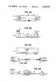
- FIG. 1Ais a plan view of the bottom of a charging base of the invention.
- FIG. 1Bis a partial cross-sectional view taken along line 1A--1A of FIG. 1.
- FIG. 2is a circuit diagram representing the rectifying and bypass circuits.
- FIGS. 3A, 3B and 3Care plan views of the front, side and back of the jumper conduit.
- FIGS. 4A and 4Bare plan views of the front and side of the conduit connecting the charging base of the invention to a wall socket.
- FIG. 5is a plan view of the bottom surface of three charging bases for different appliances interconnected by jumpers.
- FIG. 6is a circuit diagram depicting the electrical circuit of two interconnected charging bases.
- an electrical charging base for a battery-powered appliancewhich has an electrical charging contact, comprises a frame defining a shaped cavity for receiving the appliance in only one orientation.
- the base 10comprises a frame 12 defining a shaped cavity for receiving an appliance in only one orientation.
- FIG. 1Adepicts the bottom surface of frame 12, the shaped cavity is open to the top surface of frame 12.
- the view on the bottom surfaceindicates the shape of cavity 14 by means of the projection 16 created when forming the cavity in the plastic base.
- a cross-sectional view of a portion of the cavitymay be seen in FIG. 1B.
- the framecomprises a back 18 and a front 20 defined by opposed side walls 22 and opposed end walls 24.
- the side and end wallsdefine the plane of and a substantially rectangular perimeter for back 18.
- the framemay include a pair of projections 26 in the back thereof spaced along its center line, each having an opening 28 permitting attachment of frame 12 to a vertical surface. Projections 26 preferrably do not project beyond the plane defined by the side and end walls.
- Cavity 14is so shaped in frame 12 so as to receive an appliance in only one orientation. As seen in FIG. 5, charging bases for different appliances have different shaped cavities, each designed to receive its respective appliance in only one orientation.
- the charging baseincludes a rectifying circuit disposed in the frame for converting source alternating current to charging direct current, the rectifying circuit including a source input contact and a charging output contact and the charging output contact being disposed for electrical connection with the charging contact of the appliance when the appliance is disposed in the cavity.
- the rectifying circuit 30converts source alternating current 32 received by source input contact 34 to charging direct current available at charging output contact 36.
- the circuitincludes fuse 38, an RC filter comprising resistor 40 and capacitor 42, a full wave bridge rectifier 44 and a load matching resistor 46.
- load matching resistor 46In parallel to load matching resistor 46 is a light emitting diode 48 in series with a current limiting resistor 50.
- the RC filterincludes resistor 40 of 68 ⁇ and capacitor 42 of 3.3 ⁇ F
- full wave bridge rectifier 44includes four 1N4004 diodes
- load matching resistor 46is 18 ⁇
- current limiting resistor 50is 220 ⁇ .
- various changes to the rectifying circuitmay be made as known by those skilled in the art.
- the rectifying circuit 30is disposed in a cavity 52 in the bottom of frame 12.
- a cover 54is placed over cavity 52 enclosing the rectifier circuit in frame 12.
- Source input contact 34 of circuit 30is connected to a first male contact 56 in plate 54 covering the circuit disposed in cavity 52.
- Charging output contact 36is connected to a second male contact 58 disposed for electrical connection with the charging contact of the appliance when the appliance is disposed into cavity 14.
- second male contact 58protrudes into one end of cavity 14.
- the charging basealso includes a source output contact disposed in the frame and a bypass circuit disposed in the frame for electrically connecting the source input contact to the source output contact.
- electrical conductors 60 and 62are in electrical contact at one end thereof with rectifier circuit 30 in parallel with source input contact 34. The other end of conductors 60, 62 terminate in source output contact 64.
- First female contact 66 in cover 54 enclosing circuit 30 within frame 12is electrically connected to source output contact 64.
- the inventionpreferably includes jumper means for electrically connecting the source output contact to a source input contact of a second charging base for another appliance.
- a preferred embodiment of the jumper meansis a jumper 69 including an electrical conductor 70 having a female contact 72 at one end complementary to first male contact 56 comprising source input contact 34 and having a male contact 74 at the other end complementary to a female contact on a second charging base comprising a source output contact.
- electrical conductor 70 and its respective terminal contacts 72, 74are secured within a rigid frame 76 having a predetermined length to permit interconnection of adjacent charging bases having contiguous side walls 22 as depicted in FIG. 5.
- the jumper meansinclude means for fixing together the frame of the charging base and the frame of the second charging base.
- the rigid frame 76 of jumper 69includes opposed notches 80 disposed to engage complementary notches 82 in side walls 22 of frames 12.
- adjacent charging basesmay be secured together by the cooperation of the notches 80 in frame 76 of jumper 69 and notches 82 in the contiguous side walls 22 of adjacent frames 12.
- frame 76 and contacts 72, 74have dimensions such that the outside surface of a rigid frame 76 of jumper 69 is coplanar with the plane of back 18 defined by the perimeter side and end walls 22, 24 of adjacent interconnected frames 12.
- jumper 69electrically interconnects conductors 60, 62 constituting a bypass circuit of one base to source input contact 34 of an adjacent base thereby providing source alternating current to a rectifier circuit 30 and to source output contact 64 of the adjacent charging base.
- the charging basepreferably includes a conduit for electrically connecting the alternating current source to the source input contact.
- conduit 90is electrically connected to first female contact 56 comprising source input contact 34 and is connected at the other end to a standard household wall socket.
- conduit 90has a standard plug 92 on one end and a female plug 94 at the other end for mating with male contact 56 in one of the charging bases.
- Plug 94has a groove 56 disposed for engaging notch 82 in side wall 22 of frame 12. Plug 94 is so sized as to be coplanar with the plane of back 18 when mated with male contact 56.
Landscapes
- Engineering & Computer Science (AREA)
- Power Engineering (AREA)
- Charge And Discharge Circuits For Batteries Or The Like (AREA)
Abstract
Description
1. Field of the Invention
This invention relates to charging bases for battery-powered appliances and, in particular, charging bases with the capability of being electrically connected in series.
2. Description of Related Art
Recent developments have made household appliances powered by rechargeable batteries practical. Each of these appliances, such as a small vacuum, a scrub brush, a shoe polisher, and various lights, has an individual charging base. The charging base is designed to hold the appliance in a convenient position, frequently mounted on a wall, and simultaneously to charge the battery through a charging circuit in the base. Each such base must be electrically connected to a household electric socket.
The necessity for an individual wall socket for each charging base originally did not present a problem. As the number of such appliances increases, however, the limited number of available household sockets presents a disadvantage to use of several such appliances. This is particularly the situation where several such appliances, such as kitchen appliances, are intended for use in the same general location.
The present invention overcomes this disadvantage of known rechargeable appliances by providing a charging base capable of being electrically connected in series with other such bases. The invention permits placement of an array of such appliances in one location while requiring only one electric wall socket.
Additional advantages of the invention are set forth in part in the description which follows, and in part will be obvious from the description, or may be learned by practice of the invention.
The objects and advantages of the invention may be realized and attained by means of the instrumentalities and combinations particularly pointed out in the appended claims.
The invention is directed to an electrical charging base for a battery-powered appliance having an electrical charging contact, the base comprising a frame defining a shaped cavity for receiving the appliance in only one orientation; a rectifying circuit disposed in the frame for converting source alternating current to charging direct current, the rectifying circuit including a source input contact and a charging output contact, the charging output contact being disposed for electrical connection with the charging contact of the appliance when the appliance is disposed in the cavity; a source output contact disposed in the frame; and a bypass circuit disposed in the frame for electrically connecting the source input contact with source output contact.
Preferably, the invention includes jumper means for electrically connecting the source output contact to a source input contact of a second charging base for another appliance.
The jumper means is preferably an electrical conduit having contacts at each end, the contacts being respectively complementary to the source output contact of one base and the source input contact of a second base.
It is preferred that the jumper means also include means for fixing together the frames of two adjacent charging bases.
The accompanying drawings, which are incorporated in and constitute a part of the specification, illustrate embodiments of the invention, and, together with the description, serve to explain the principles of the invention.
FIG. 1A is a plan view of the bottom of a charging base of the invention.
FIG. 1B is a partial cross-sectional view taken along line 1A--1A of FIG. 1.
FIG. 2 is a circuit diagram representing the rectifying and bypass circuits.
FIGS. 3A, 3B and 3C are plan views of the front, side and back of the jumper conduit.
FIGS. 4A and 4B are plan views of the front and side of the conduit connecting the charging base of the invention to a wall socket.
FIG. 5 is a plan view of the bottom surface of three charging bases for different appliances interconnected by jumpers.
FIG. 6 is a circuit diagram depicting the electrical circuit of two interconnected charging bases.
Reference will now be made in detail to the present preferred embodiments of the invention, examples of which are illustrated in the accompanying drawings.
In accordance with the invention, an electrical charging base for a battery-powered appliance which has an electrical charging contact, comprises a frame defining a shaped cavity for receiving the appliance in only one orientation. In the preferred embodiment, as depicted in FIG. 1A, thebase 10 comprises aframe 12 defining a shaped cavity for receiving an appliance in only one orientation. FIG. 1A depicts the bottom surface offrame 12, the shaped cavity is open to the top surface offrame 12. The view on the bottom surface indicates the shape ofcavity 14 by means of theprojection 16 created when forming the cavity in the plastic base. A cross-sectional view of a portion of the cavity may be seen in FIG. 1B.
Preferably the frame comprises aback 18 and afront 20 defined byopposed side walls 22 and opposedend walls 24. The side and end walls define the plane of and a substantially rectangular perimeter forback 18. The frame may include a pair ofprojections 26 in the back thereof spaced along its center line, each having an opening 28 permitting attachment offrame 12 to a vertical surface.Projections 26 preferrably do not project beyond the plane defined by the side and end walls.
In accordance with the invention, the charging base includes a rectifying circuit disposed in the frame for converting source alternating current to charging direct current, the rectifying circuit including a source input contact and a charging output contact and the charging output contact being disposed for electrical connection with the charging contact of the appliance when the appliance is disposed in the cavity. As seen in FIG. 2, the rectifyingcircuit 30 converts sourcealternating current 32 received bysource input contact 34 to charging direct current available atcharging output contact 36. Betweensource input contact 34 andcharging output contact 36, the circuit includesfuse 38, an RCfilter comprising resistor 40 andcapacitor 42, a fullwave bridge rectifier 44 and aload matching resistor 46. In parallel to load matchingresistor 46 is alight emitting diode 48 in series with a current limitingresistor 50. In a preferred embodiment, where source alternating current is 120 VAC,fuse 38 is 0.25A, the RC filter includesresistor 40 of 68Ω andcapacitor 42 of 3.3μF, fullwave bridge rectifier 44 includes four 1N4004 diodes,load matching resistor 46 is 18Ω and current limitingresistor 50 is 220Ω. Naturally, depending on the appliance battery being charged and the source current, various changes to the rectifying circuit may be made as known by those skilled in the art.
Referring to FIGS. 1A and 1B, the rectifyingcircuit 30 is disposed in acavity 52 in the bottom offrame 12. Acover 54 is placed overcavity 52 enclosing the rectifier circuit inframe 12.Source input contact 34 ofcircuit 30 is connected to a firstmale contact 56 inplate 54 covering the circuit disposed incavity 52.Charging output contact 36 is connected to a secondmale contact 58 disposed for electrical connection with the charging contact of the appliance when the appliance is disposed intocavity 14. Preferably, secondmale contact 58 protrudes into one end ofcavity 14.
In accordance with the invention, the charging base also includes a source output contact disposed in the frame and a bypass circuit disposed in the frame for electrically connecting the source input contact to the source output contact. As embodied herein and depicted in FIGS. 1A and 2,electrical conductors 60 and 62 are in electrical contact at one end thereof withrectifier circuit 30 in parallel withsource input contact 34. The other end ofconductors 60, 62 terminate insource output contact 64. Firstfemale contact 66 incover 54enclosing circuit 30 withinframe 12 is electrically connected to sourceoutput contact 64. By this arrangement, source current is conveyed simultaneously throughrectifier circuit 30 to chargingoutput contact 36 and throughconductors 60, 62 constituting a bypass circuit to sourceoutput contact 64.
The invention preferably includes jumper means for electrically connecting the source output contact to a source input contact of a second charging base for another appliance. As depicted in FIGS. 3A, 3B and 3C, a preferred embodiment of the jumper means is ajumper 69 including anelectrical conductor 70 having afemale contact 72 at one end complementary to firstmale contact 56 comprisingsource input contact 34 and having amale contact 74 at the other end complementary to a female contact on a second charging base comprising a source output contact. In a preferred embodiment,electrical conductor 70 and its respectiveterminal contacts rigid frame 76 having a predetermined length to permit interconnection of adjacent charging bases havingcontiguous side walls 22 as depicted in FIG. 5.
It is also preferred that the jumper means include means for fixing together the frame of the charging base and the frame of the second charging base. As seen in FIG. 3A, 3B and 3C, therigid frame 76 ofjumper 69 includes opposednotches 80 disposed to engagecomplementary notches 82 inside walls 22 offrames 12. Thus, as seen in FIG. 5, adjacent charging bases may be secured together by the cooperation of thenotches 80 inframe 76 ofjumper 69 andnotches 82 in thecontiguous side walls 22 ofadjacent frames 12.
Preferably,frame 76 andcontacts rigid frame 76 ofjumper 69 is coplanar with the plane of back 18 defined by the perimeter side and endwalls
By usingjumpers 69, a plurality of chargingbases 10 may be arranged in an interconnected array as seen in FIG. 5. Referring to FIG. 6,jumper 69 electrically interconnectsconductors 60, 62 constituting a bypass circuit of one base to sourceinput contact 34 of an adjacent base thereby providing source alternating current to arectifier circuit 30 and to sourceoutput contact 64 of the adjacent charging base.
The charging base preferably includes a conduit for electrically connecting the alternating current source to the source input contact. As seen in FIG. 5,conduit 90 is electrically connected to firstfemale contact 56 comprisingsource input contact 34 and is connected at the other end to a standard household wall socket. As seen in FIGS. 4A and 4B,conduit 90 has astandard plug 92 on one end and afemale plug 94 at the other end for mating withmale contact 56 in one of the charging bases.Plug 94 has agroove 56 disposed for engagingnotch 82 inside wall 22 offrame 12.Plug 94 is so sized as to be coplanar with the plane of back 18 when mated withmale contact 56.
It will be apparent to those skilled in the art that various modifications and variations may be made to the charging base of the invention without departing from the scope or spirft of the invention.
Claims (7)
1. An electrical charging base for a battery-powered appliance having an electrical charging contact, said base comprising:
(a) a frame defining a shaped cavity for receiving said appliance in only one orientation;
(b) a rectifying circuit disposed in said frame for converting source alternating current to charging direct current, said source alternating current originating from a source outside of said charging base, said rectifying circuit including a source input contact and a charging output contact, said charging output contact being disposed for electrical connection with said charging contact when said appliance is disposed in said cavity;
(c) a source output contact disposed in said frame;
(d) a bypass circuit disposed in said frame for electrically connecting said source input contact to said source output contact, said bypass circuit transmitting source unaltered AC current from said source input contact to said source output contact; and
(e) jumper means for electrically connecting said source output contact to a source input contact of a second charging base for another appliance.
2. The charging base of claim 1 wherein said source input contact is a first male contact, said charging output contact is a second male contact, and said source output contact is a first female contact.
3. The charging base of claim 1 wherein said jumper means includes means for fixing together said frame and the frame of said second charging base.
4. An array of charging bases for a plurality of battery-powered appliances, each appliance having an electrical charging contact, the array comprising:
(a) a plurality of frames each having a top and a bottom defined by end and side surfaces, said frames being disposed in side-adjacent relation and each frame having a shaped cavity in its top for receiving one of said appliances in only one orientation:
(b) a rectifying circuit disposed in the bottom of each said frame for individually converting in each said frame source alternating current to charging direct current, each said rectifying circuit including a source input contact and a charging output contact, each said charging output contact being disposed in its respective frame for electrical connection with the charging contact of the appliance disposed in said cavity;
(c) a source output contact disposed in each said frame;
(d) a bypass circuit disposed in each said frame for electrically connecting the respective source input contact to the respective source output contact, the bypass circuit of each said frame transmitting unaltered AC source current from said source input contact to the respective source output contact; and
(e) jumper means for electrically connecting the source output contact of one said frame to the source input contact of an adjacent frame.
5. The array of claim 4 wherein said jumper means includes means for securing together contiguous sides of said adjacent frames.
6. The array of claim 4 wherein said bypass circuit disposed in each said frame bypasses the respective rectifying circuit in each said frame.
7. An electrical charging base for a battery-powered appliance having an electrical charging contact, said base comprising:
a frame defining a shaped cavity for receiving said appliance in only one orientation;
a rectifying circuit disposed in said frame for converting source alternating current to charging direct current, said rectifying circuit including a source input first male contact and a charging output second male contact, said second male contact being disposed for electrical connection with said charging contact when said appliance is disposed in said cavity;
a source output first female contact disposed in said frame;
a bypass circuit disposed in said frame for electrically connecting said source input contact to said source output contact; and
jumper means for electrically connecting said source output female contact to a source input male contact of a second charging base for another appliance, said jumper means including an electrical conductor having a third male contact complimentary to said first female contact at one end and a second female contact compliementary to said input male contact on said second charging base at the other end.
Priority Applications (1)
| Application Number | Priority Date | Filing Date | Title |
|---|---|---|---|
| US06/686,590US4716352A (en) | 1984-12-26 | 1984-12-26 | Charging base for a battery-powered appliance |
Applications Claiming Priority (1)
| Application Number | Priority Date | Filing Date | Title |
|---|---|---|---|
| US06/686,590US4716352A (en) | 1984-12-26 | 1984-12-26 | Charging base for a battery-powered appliance |
Publications (1)
| Publication Number | Publication Date |
|---|---|
| US4716352Atrue US4716352A (en) | 1987-12-29 |
Family
ID=24756937
Family Applications (1)
| Application Number | Title | Priority Date | Filing Date |
|---|---|---|---|
| US06/686,590Expired - LifetimeUS4716352A (en) | 1984-12-26 | 1984-12-26 | Charging base for a battery-powered appliance |
Country Status (1)
| Country | Link |
|---|---|
| US (1) | US4716352A (en) |
Cited By (91)
| Publication number | Priority date | Publication date | Assignee | Title |
|---|---|---|---|---|
| US5124532A (en)* | 1990-07-09 | 1992-06-23 | Hafey Marilyn J | Organizer for cordless electrically energized hair salon utensils |
| USD356295S (en) | 1993-07-07 | 1995-03-14 | Motorola, Inc. | AC power connector |
| US5914585A (en)* | 1996-02-20 | 1999-06-22 | Norand Corporation | Power sharing in computing systems with a plurality of electronic devices |
| US6137260A (en)* | 1999-01-29 | 2000-10-24 | Intermec Ip Corp. | Multifunction connector for hand-held terminal docks |
| US6656626B1 (en) | 1999-06-01 | 2003-12-02 | Porter-Cable Corporation | Cordless power tool battery release mechanism |
| US20050024021A1 (en)* | 2003-05-07 | 2005-02-03 | Milwaukee Electric Tool Corporation | Battery charger and assembly |
| USD509930S1 (en) | 2003-10-15 | 2005-09-20 | Black & Decker Inc. | Hand-held cordless vacuum cleaner |
| USD530010S1 (en) | 2004-03-17 | 2006-10-10 | Water Pik, Inc. | Base for an oral implement |
| US7183745B2 (en) | 2000-08-11 | 2007-02-27 | Milwaukee Electric Tool Corporation | Adapter for a power tool battery |
| US7243734B2 (en) | 2005-01-10 | 2007-07-17 | Nanjing Chervon Industry Co., Ltd. | Power tool with battery power supply |
| US20070224492A1 (en)* | 2000-08-11 | 2007-09-27 | Milwaukee Electric Tool Corporation | Adapter for a power tool battery |
| US7339350B2 (en) | 2000-08-11 | 2008-03-04 | Milwaukee Electric Tool Corporation | Electrical combination including a battery pack |
| USD565175S1 (en) | 2006-02-24 | 2008-03-25 | Water Pik, Inc. | Water jet base |
| WO2008021323A3 (en)* | 2006-08-11 | 2008-04-17 | Marche Designs | Flashing flare warning device |
| US7391182B2 (en) | 2001-06-20 | 2008-06-24 | Helen Of Troy Limited | Autoilluminating rechargeable lamp system |
| US7400112B2 (en) | 2001-06-20 | 2008-07-15 | Helen Of Troy Limited | Autoilluminating rechargeable lamp system |
| USD574952S1 (en) | 2006-02-24 | 2008-08-12 | Water Pik, Inc. | Water jet handle |
| USD588985S1 (en) | 2007-10-17 | 2009-03-24 | Black & Decker Inc. | Battery charger |
| USRE40681E1 (en) | 1994-06-10 | 2009-03-24 | Linvatec Corporation | Combination rechargeable, detachable battery system and power tool |
| US20100000067A1 (en)* | 2001-08-24 | 2010-01-07 | Black & Decker Inc. | Battery For A Power Tool With A Battery Pack Ejector |
| US7670141B2 (en) | 2006-07-07 | 2010-03-02 | Water Pik, Inc. | Oral irrigator |
| USRE41628E1 (en) | 2001-06-20 | 2010-09-07 | Helen Of Troy Limited | Autoilluminating lamp system |
| US7845046B2 (en) | 2003-10-15 | 2010-12-07 | Black & Decker, Inc. | Hand-held cordless vacuum cleaner |
| USD629884S1 (en) | 2009-12-16 | 2010-12-28 | Water Pik, Inc. | Powered irrigator for sinus cavity rinse |
| US8032984B2 (en) | 2006-01-27 | 2011-10-11 | Black & Decker Inc. | Vacuum cleaner filter cleaning mechanisms |
| US8113832B2 (en) | 2002-12-31 | 2012-02-14 | Water Pik, Inc. | Hand held oral irrigator |
| USD670373S1 (en) | 2010-12-16 | 2012-11-06 | Water Pik, Inc. | Powered irrigator for sinus cavity rinse |
| US8408483B2 (en) | 2006-02-24 | 2013-04-02 | Water Pik, Inc. | Adjustable flow regulator for dental water jet |
| USD707350S1 (en) | 2012-10-11 | 2014-06-17 | Water Pik, Inc. | Handheld water flosser |
| US8801667B2 (en) | 2009-12-16 | 2014-08-12 | Water Pik, Inc. | Pump for powered irrigator for sinus cavity rinse |
| USD714930S1 (en) | 2013-03-14 | 2014-10-07 | Water Pik, Inc. | Reservoir for water flosser |
| USD714929S1 (en) | 2013-03-14 | 2014-10-07 | Water Pik, Inc. | Base for water flosser |
| USD717427S1 (en) | 2013-03-14 | 2014-11-11 | Water Pik, Inc. | Handle for water flosser |
| USD725770S1 (en) | 2013-03-14 | 2015-03-31 | Water Pik, Inc. | Reservoir for water flosser |
| US20160113132A1 (en)* | 2014-10-20 | 2016-04-21 | Enphase Energy, Inc. | Energy storage/delivery device mounting plate |
| USD756122S1 (en) | 2009-01-28 | 2016-05-17 | Water Pik, Inc. | Oral irrigator tip |
| USD772396S1 (en) | 2014-12-01 | 2016-11-22 | Water Pik, Inc. | Handheld oral irrigator |
| USD772397S1 (en) | 2014-12-01 | 2016-11-22 | Water Pik, Inc. | Oral irrigator with a charging device |
| USD780908S1 (en) | 2015-11-03 | 2017-03-07 | Water Pik, Inc. | Handheld oral irrigator |
| USD782656S1 (en) | 2016-01-25 | 2017-03-28 | Water Pik, Inc. | Oral irrigator |
| USD782657S1 (en) | 2016-03-02 | 2017-03-28 | Water Pik, Inc. | Oral irrigator handle |
| USD783809S1 (en) | 2016-01-25 | 2017-04-11 | Water Pik, Inc. | Oral irrigator handle |
| USD783810S1 (en) | 2016-02-22 | 2017-04-11 | Water Pik, Inc. | Handle for an oral irrigator |
| USD786422S1 (en) | 2016-01-25 | 2017-05-09 | Water Pik, Inc. | Oral irrigator |
| USD788907S1 (en) | 2013-03-14 | 2017-06-06 | Water Pik, Inc. | Water flosser base unit with reservoir lid |
| USD794773S1 (en) | 2016-07-19 | 2017-08-15 | Water Pik, Inc. | Oral irrigator |
| USD796028S1 (en) | 2016-07-19 | 2017-08-29 | Water Pik, Inc. | Oral irrigator |
| USD802120S1 (en) | 2007-02-27 | 2017-11-07 | Water Pik, Inc. | Tip for oral irrigator |
| USD802119S1 (en) | 2016-03-02 | 2017-11-07 | Water Pik, Inc. | Oral irrigator |
| USD802747S1 (en) | 2016-07-19 | 2017-11-14 | Water Pik, Inc. | Reservoir for oral irrigator |
| USD804016S1 (en) | 2016-02-05 | 2017-11-28 | Water Pik, Inc. | Handheld oral irrigator |
| USD804018S1 (en) | 2016-07-19 | 2017-11-28 | Water Pik, Inc. | Base for an oral irrigator |
| USD807822S1 (en) | 2016-07-19 | 2018-01-16 | Water Pik, Inc. | Power supply cartridge |
| USD809651S1 (en) | 2016-07-19 | 2018-02-06 | Water Pik, Inc. | Combination base and reservoir for an oral irrigator |
| USD809650S1 (en) | 2016-02-22 | 2018-02-06 | Water Pik, Inc. | Oral irrigator |
| US9980793B2 (en) | 2013-11-27 | 2018-05-29 | Water Pik, Inc. | Oral hygiene system |
| USD819956S1 (en) | 2016-01-25 | 2018-06-12 | Water Pik, Inc. | Kit bag |
| USD822196S1 (en) | 2016-01-14 | 2018-07-03 | Water Pik, Inc. | Oral irrigator |
| USD822825S1 (en) | 2016-12-15 | 2018-07-10 | Water Pik, Inc. | Oral irrigator unit |
| USD822826S1 (en) | 2016-12-15 | 2018-07-10 | Water Pik, Inc. | Oral irrigator base |
| US10016254B2 (en) | 2013-12-20 | 2018-07-10 | Water Pik, Inc. | Dental water jet |
| US10022207B2 (en) | 2013-11-27 | 2018-07-17 | Water Pik, Inc. | Oral irrigator with slide pause switch |
| USD825741S1 (en) | 2016-12-15 | 2018-08-14 | Water Pik, Inc. | Oral irrigator handle |
| USD829887S1 (en) | 2017-02-06 | 2018-10-02 | Water Pik, Inc. | Oral irrigator reservoir |
| USD829886S1 (en) | 2016-12-15 | 2018-10-02 | Water Pik, Inc. | Oral irrigator base |
| US10105201B2 (en) | 2012-10-11 | 2018-10-23 | Water Pik, Inc. | Interdental cleaner using water supply |
| USD832420S1 (en) | 2016-12-15 | 2018-10-30 | Water Pik, Inc. | Oral irrigator base |
| USD832419S1 (en) | 2016-12-15 | 2018-10-30 | Water Pik, Inc. | Oral irrigator unit |
| USD832418S1 (en) | 2016-12-15 | 2018-10-30 | Water Pik, Inc. | Oral irrigator base |
| USD833000S1 (en) | 2016-12-15 | 2018-11-06 | Water Pik, Inc. | Oral irrigator unit |
| USD833602S1 (en) | 2017-02-06 | 2018-11-13 | Water Pik, Inc. | Oral irrigator base |
| USD833601S1 (en) | 2017-02-06 | 2018-11-13 | Water Pik, Inc. | Oral irrigator |
| USD833600S1 (en) | 2016-12-15 | 2018-11-13 | Water Pik, Inc. | Oral irrigator reservoir |
| USD834180S1 (en) | 2016-12-15 | 2018-11-20 | Water Pik, Inc. | Oral irrigator base |
| USD839409S1 (en) | 2016-12-15 | 2019-01-29 | Water Pik, Inc. | Oral irrigator unit |
| USD840022S1 (en) | 2016-12-15 | 2019-02-05 | Water Pik, Inc. | Oral irrigator handle |
| USD840023S1 (en) | 2016-12-15 | 2019-02-05 | Water Pik, Inc. | Oral irrigator reservoir |
| US10258442B2 (en) | 2009-03-20 | 2019-04-16 | Water Pik, Inc. | Oral irrigator appliance with radiant energy delivery for bactericidal effect |
| USD867579S1 (en) | 2016-12-15 | 2019-11-19 | Water Pik, Inc. | Oral irrigator unit |
| USD868243S1 (en) | 2018-03-16 | 2019-11-26 | Water Pik, Inc. | Oral irrigator tip |
| USD877324S1 (en) | 2018-05-17 | 2020-03-03 | Water Pik, Inc. | Oral irrigator handle |
| USD888936S1 (en) | 2019-02-22 | 2020-06-30 | Water Pik, Inc. | Cordless water flosser |
| USD889636S1 (en) | 2019-02-22 | 2020-07-07 | Water Pik, Inc. | Water flosser |
| US10779922B2 (en) | 2016-12-15 | 2020-09-22 | Water Pik, Inc. | Pause valve and swivel assemblies for oral irrigator handle |
| US10835356B2 (en) | 2016-01-25 | 2020-11-17 | Water Pik, Inc. | Swivel assembly for oral irrigator handle |
| US10993867B2 (en) | 2016-03-02 | 2021-05-04 | Water Pik, Inc. | Actuation assembly for an oral irrigator |
| US11213376B2 (en) | 2016-01-25 | 2022-01-04 | Water Pik, Inc. | Reduced form factor oral irrigator |
| US11389279B2 (en) | 2016-12-15 | 2022-07-19 | Water Pik, Inc. | Oral irrigator with magnetic attachment |
| USD966498S1 (en) | 2020-09-15 | 2022-10-11 | Water Pik, Inc. | Oral irrigator |
| US11826214B2 (en) | 2014-12-01 | 2023-11-28 | Water Pik, Inc. | Oral irrigator |
| USD1016274S1 (en) | 2021-02-16 | 2024-02-27 | Water Pik, Inc. | Oral irrigator |
Citations (3)
| Publication number | Priority date | Publication date | Assignee | Title |
|---|---|---|---|---|
| US3696283A (en)* | 1970-04-15 | 1972-10-03 | John W Ackley | Modular battery charger |
| US4096428A (en)* | 1976-10-07 | 1978-06-20 | Optical Associates, Inc. | Instrument supporting transformer unit |
| US4225814A (en)* | 1978-08-11 | 1980-09-30 | Black & Decker, Inc. | Cordless vacuum cleaner storing and recharging system |
- 1984
- 1984-12-26USUS06/686,590patent/US4716352A/ennot_activeExpired - Lifetime
Patent Citations (3)
| Publication number | Priority date | Publication date | Assignee | Title |
|---|---|---|---|---|
| US3696283A (en)* | 1970-04-15 | 1972-10-03 | John W Ackley | Modular battery charger |
| US4096428A (en)* | 1976-10-07 | 1978-06-20 | Optical Associates, Inc. | Instrument supporting transformer unit |
| US4225814A (en)* | 1978-08-11 | 1980-09-30 | Black & Decker, Inc. | Cordless vacuum cleaner storing and recharging system |
Non-Patent Citations (2)
| Title |
|---|
| pp. 5 5, Nickel Cadmium Battery, Application Engineering Handbook, Second Edition.* |
| pp. 5--5, Nickel-Cadmium Battery, Application Engineering Handbook, Second Edition. |
Cited By (154)
| Publication number | Priority date | Publication date | Assignee | Title |
|---|---|---|---|---|
| US5124532A (en)* | 1990-07-09 | 1992-06-23 | Hafey Marilyn J | Organizer for cordless electrically energized hair salon utensils |
| USD356295S (en) | 1993-07-07 | 1995-03-14 | Motorola, Inc. | AC power connector |
| USRE40848E1 (en) | 1994-06-10 | 2009-07-14 | Pitzen James F | Combination rechargeable, detachable battery system and power tool |
| USRE40681E1 (en) | 1994-06-10 | 2009-03-24 | Linvatec Corporation | Combination rechargeable, detachable battery system and power tool |
| US5914585A (en)* | 1996-02-20 | 1999-06-22 | Norand Corporation | Power sharing in computing systems with a plurality of electronic devices |
| US6137260A (en)* | 1999-01-29 | 2000-10-24 | Intermec Ip Corp. | Multifunction connector for hand-held terminal docks |
| US6656626B1 (en) | 1999-06-01 | 2003-12-02 | Porter-Cable Corporation | Cordless power tool battery release mechanism |
| US7429430B2 (en) | 1999-06-01 | 2008-09-30 | Black & Decker Inc. | Cordless power tool battery release mechanism |
| US7443137B2 (en) | 2000-08-11 | 2008-10-28 | Milwaukee Electric Tool Corporation | Adapter for a power tool battery |
| US20070224492A1 (en)* | 2000-08-11 | 2007-09-27 | Milwaukee Electric Tool Corporation | Adapter for a power tool battery |
| US7339350B2 (en) | 2000-08-11 | 2008-03-04 | Milwaukee Electric Tool Corporation | Electrical combination including a battery pack |
| US7183745B2 (en) | 2000-08-11 | 2007-02-27 | Milwaukee Electric Tool Corporation | Adapter for a power tool battery |
| US7391182B2 (en) | 2001-06-20 | 2008-06-24 | Helen Of Troy Limited | Autoilluminating rechargeable lamp system |
| USRE41628E1 (en) | 2001-06-20 | 2010-09-07 | Helen Of Troy Limited | Autoilluminating lamp system |
| US7400112B2 (en) | 2001-06-20 | 2008-07-15 | Helen Of Troy Limited | Autoilluminating rechargeable lamp system |
| US8312937B2 (en) | 2001-08-24 | 2012-11-20 | Black & Decker Inc. | Battery for a power tool with a battery pack ejector |
| US20100000067A1 (en)* | 2001-08-24 | 2010-01-07 | Black & Decker Inc. | Battery For A Power Tool With A Battery Pack Ejector |
| US10617500B2 (en) | 2002-12-31 | 2020-04-14 | Water Pik, Inc. | Oral irrigator |
| US9980794B2 (en) | 2002-12-31 | 2018-05-29 | Water Pik, Inc. | Irrigating device with variable pressure pulse |
| US8113832B2 (en) | 2002-12-31 | 2012-02-14 | Water Pik, Inc. | Hand held oral irrigator |
| GB2401484B (en)* | 2003-05-07 | 2007-09-26 | Milwaukee Electric Tool Corp | Battery charging apparatus |
| US20050024021A1 (en)* | 2003-05-07 | 2005-02-03 | Milwaukee Electric Tool Corporation | Battery charger and assembly |
| US20080036420A1 (en)* | 2003-05-07 | 2008-02-14 | Zeiler Jeffrey M | Battery charger and assembly |
| US7659696B2 (en) | 2003-05-07 | 2010-02-09 | Milwaukee Electric Tool Corporation | Battery charger and assembly |
| US8549704B2 (en) | 2003-10-15 | 2013-10-08 | Black & Decker Inc. | Hand-held cordless vacuum cleaner |
| USD509930S1 (en) | 2003-10-15 | 2005-09-20 | Black & Decker Inc. | Hand-held cordless vacuum cleaner |
| USD521450S1 (en) | 2003-10-15 | 2006-05-23 | Black & Decker Inc. | Recharging base for a cordless hand tool |
| US7845046B2 (en) | 2003-10-15 | 2010-12-07 | Black & Decker, Inc. | Hand-held cordless vacuum cleaner |
| USD530010S1 (en) | 2004-03-17 | 2006-10-10 | Water Pik, Inc. | Base for an oral implement |
| US7243734B2 (en) | 2005-01-10 | 2007-07-17 | Nanjing Chervon Industry Co., Ltd. | Power tool with battery power supply |
| US8032984B2 (en) | 2006-01-27 | 2011-10-11 | Black & Decker Inc. | Vacuum cleaner filter cleaning mechanisms |
| USD565175S1 (en) | 2006-02-24 | 2008-03-25 | Water Pik, Inc. | Water jet base |
| USD574952S1 (en) | 2006-02-24 | 2008-08-12 | Water Pik, Inc. | Water jet handle |
| US11872097B2 (en) | 2006-02-24 | 2024-01-16 | Water Pik, Inc. | Dental water jet with storage container reservoir cover |
| US11432916B2 (en) | 2006-02-24 | 2022-09-06 | Water Pik, Inc. | Oral irrigator with handle support |
| US10010389B2 (en) | 2006-02-24 | 2018-07-03 | Water Pik, Inc. | Dental water jet device |
| US8408483B2 (en) | 2006-02-24 | 2013-04-02 | Water Pik, Inc. | Adjustable flow regulator for dental water jet |
| US11197745B2 (en) | 2006-02-24 | 2021-12-14 | Water Pik, Inc. | Removable fluid connection fitting for oral irrigator |
| US9050157B2 (en) | 2006-02-24 | 2015-06-09 | Water Pik, Inc. | Dental water jet with storage container reservoir cover |
| US8641649B2 (en) | 2006-02-24 | 2014-02-04 | Water Pik, Inc. | Pump for dental water jet |
| US8888727B2 (en) | 2006-02-24 | 2014-11-18 | Water Pik, Inc. | Vibration damping for dental water jet |
| US8808209B2 (en) | 2006-02-24 | 2014-08-19 | Water Pik, Inc. | Dental water jet irrigator handle |
| US8403665B2 (en) | 2006-07-07 | 2013-03-26 | Water Pik, Inc. | Oral irrigator |
| US9775692B2 (en) | 2006-07-07 | 2017-10-03 | Water Pik, Inc. | Oral irrigator with variable pressure |
| US7670141B2 (en) | 2006-07-07 | 2010-03-02 | Water Pik, Inc. | Oral irrigator |
| USD747464S1 (en) | 2006-07-07 | 2016-01-12 | Water Pik, Inc. | Handheld oral irrigator |
| WO2008021323A3 (en)* | 2006-08-11 | 2008-04-17 | Marche Designs | Flashing flare warning device |
| USD802120S1 (en) | 2007-02-27 | 2017-11-07 | Water Pik, Inc. | Tip for oral irrigator |
| USD867580S1 (en) | 2007-02-27 | 2019-11-19 | Water Pik, Inc. | Oral irrigator tip with bristles |
| USD588985S1 (en) | 2007-10-17 | 2009-03-24 | Black & Decker Inc. | Battery charger |
| USD756122S1 (en) | 2009-01-28 | 2016-05-17 | Water Pik, Inc. | Oral irrigator tip |
| US10258442B2 (en) | 2009-03-20 | 2019-04-16 | Water Pik, Inc. | Oral irrigator appliance with radiant energy delivery for bactericidal effect |
| US11173020B2 (en) | 2009-03-20 | 2021-11-16 | Water Pik, Inc. | Oral irrigator appliance with radiant energy delivery for bactericidal effect |
| USD629884S1 (en) | 2009-12-16 | 2010-12-28 | Water Pik, Inc. | Powered irrigator for sinus cavity rinse |
| US9061096B2 (en) | 2009-12-16 | 2015-06-23 | Water Pik, Inc. | Powered irrigator for sinus cavity rinse |
| US8801667B2 (en) | 2009-12-16 | 2014-08-12 | Water Pik, Inc. | Pump for powered irrigator for sinus cavity rinse |
| US8808245B2 (en) | 2009-12-16 | 2014-08-19 | Water Pik, Inc. | Powered irrigator for sinus cavity rinse with detachable reservoir |
| USD694398S1 (en) | 2010-12-16 | 2013-11-26 | Water Pik, Inc. | Powered irrigator for sinus cavity rinse |
| USD670373S1 (en) | 2010-12-16 | 2012-11-06 | Water Pik, Inc. | Powered irrigator for sinus cavity rinse |
| US10105201B2 (en) | 2012-10-11 | 2018-10-23 | Water Pik, Inc. | Interdental cleaner using water supply |
| USD707350S1 (en) | 2012-10-11 | 2014-06-17 | Water Pik, Inc. | Handheld water flosser |
| USD731640S1 (en) | 2013-03-14 | 2015-06-09 | Water Pik, Inc. | Reservoir for a water flosser |
| USD754330S1 (en) | 2013-03-14 | 2016-04-19 | Water Pik, Inc. | Handle for a water flosser |
| USD714930S1 (en) | 2013-03-14 | 2014-10-07 | Water Pik, Inc. | Reservoir for water flosser |
| USD714929S1 (en) | 2013-03-14 | 2014-10-07 | Water Pik, Inc. | Base for water flosser |
| USD717427S1 (en) | 2013-03-14 | 2014-11-11 | Water Pik, Inc. | Handle for water flosser |
| US9642677B2 (en) | 2013-03-14 | 2017-05-09 | Water Pik, Inc. | Oral irrigator with massage mode |
| USD718855S1 (en) | 2013-03-14 | 2014-12-02 | Water Pik, Inc. | Base for water flosser |
| USD788907S1 (en) | 2013-03-14 | 2017-06-06 | Water Pik, Inc. | Water flosser base unit with reservoir lid |
| US10945912B2 (en) | 2013-03-14 | 2021-03-16 | Water Pik, Inc. | Oral irrigator with variable output fluid characteristics |
| USD725770S1 (en) | 2013-03-14 | 2015-03-31 | Water Pik, Inc. | Reservoir for water flosser |
| USD798440S1 (en) | 2013-03-14 | 2017-09-26 | Water Pik, Inc. | Water flosser base unit |
| US9597161B2 (en) | 2013-03-14 | 2017-03-21 | Water Pik, Inc. | Oral irrigator with integrated lid and base |
| USD740936S1 (en) | 2013-03-14 | 2015-10-13 | Water Pik, Inc. | Water flosser base unit |
| US10022207B2 (en) | 2013-11-27 | 2018-07-17 | Water Pik, Inc. | Oral irrigator with slide pause switch |
| US9980793B2 (en) | 2013-11-27 | 2018-05-29 | Water Pik, Inc. | Oral hygiene system |
| US11039906B2 (en) | 2013-11-27 | 2021-06-22 | Water Pik, Inc. | Tip ejection assembly for an oral irrigator |
| US10016254B2 (en) | 2013-12-20 | 2018-07-10 | Water Pik, Inc. | Dental water jet |
| US20160113132A1 (en)* | 2014-10-20 | 2016-04-21 | Enphase Energy, Inc. | Energy storage/delivery device mounting plate |
| US9801293B2 (en)* | 2014-10-20 | 2017-10-24 | Enphase Energy, Inc. | Energy storage/delivery device mounting plate |
| USD772396S1 (en) | 2014-12-01 | 2016-11-22 | Water Pik, Inc. | Handheld oral irrigator |
| US12383387B2 (en) | 2014-12-01 | 2025-08-12 | Water Pik, Inc. | Oral irrigator |
| US11826214B2 (en) | 2014-12-01 | 2023-11-28 | Water Pik, Inc. | Oral irrigator |
| USD772397S1 (en) | 2014-12-01 | 2016-11-22 | Water Pik, Inc. | Oral irrigator with a charging device |
| USD819196S1 (en) | 2014-12-01 | 2018-05-29 | Water Pik, Inc. | Handheld oral irrigator |
| USD780908S1 (en) | 2015-11-03 | 2017-03-07 | Water Pik, Inc. | Handheld oral irrigator |
| USD907763S1 (en) | 2016-01-14 | 2021-01-12 | Water Pik, Inc. | Oral irrigator |
| USD822196S1 (en) | 2016-01-14 | 2018-07-03 | Water Pik, Inc. | Oral irrigator |
| USD880688S1 (en) | 2016-01-14 | 2020-04-07 | Water Pik, Inc. | Oral irrigator handle |
| USD873025S1 (en) | 2016-01-14 | 2020-01-21 | Water Pik, Inc. | Toothbrush handle |
| USD786422S1 (en) | 2016-01-25 | 2017-05-09 | Water Pik, Inc. | Oral irrigator |
| US11642203B2 (en) | 2016-01-25 | 2023-05-09 | Water Pik, Inc. | Oral irrigator handle with hose connector fittings |
| USD782656S1 (en) | 2016-01-25 | 2017-03-28 | Water Pik, Inc. | Oral irrigator |
| US12186147B2 (en) | 2016-01-25 | 2025-01-07 | Water Pik, Inc. | Reduced form factor oral irrigator |
| US11213376B2 (en) | 2016-01-25 | 2022-01-04 | Water Pik, Inc. | Reduced form factor oral irrigator |
| US12207983B2 (en) | 2016-01-25 | 2025-01-28 | Water Pik, Inc. | Oral irrigator handle with hose connector fittings |
| USD819956S1 (en) | 2016-01-25 | 2018-06-12 | Water Pik, Inc. | Kit bag |
| USD783809S1 (en) | 2016-01-25 | 2017-04-11 | Water Pik, Inc. | Oral irrigator handle |
| US10835356B2 (en) | 2016-01-25 | 2020-11-17 | Water Pik, Inc. | Swivel assembly for oral irrigator handle |
| USD815274S1 (en) | 2016-02-05 | 2018-04-10 | Water Pik, Inc. | Handheld oral irrigator |
| USD804016S1 (en) | 2016-02-05 | 2017-11-28 | Water Pik, Inc. | Handheld oral irrigator |
| USD809650S1 (en) | 2016-02-22 | 2018-02-06 | Water Pik, Inc. | Oral irrigator |
| USD783810S1 (en) | 2016-02-22 | 2017-04-11 | Water Pik, Inc. | Handle for an oral irrigator |
| USD873409S1 (en) | 2016-02-22 | 2020-01-21 | Water Pik, Inc. | Oral irrigator |
| USD839410S1 (en) | 2016-02-22 | 2019-01-29 | Water Pik, Inc. | Oral irrigator |
| USD802119S1 (en) | 2016-03-02 | 2017-11-07 | Water Pik, Inc. | Oral irrigator |
| US10993867B2 (en) | 2016-03-02 | 2021-05-04 | Water Pik, Inc. | Actuation assembly for an oral irrigator |
| USD782657S1 (en) | 2016-03-02 | 2017-03-28 | Water Pik, Inc. | Oral irrigator handle |
| US11607359B2 (en) | 2016-03-02 | 2023-03-21 | Water Pik, Inc. | Actuation assembly for an oral irrigator |
| USD794773S1 (en) | 2016-07-19 | 2017-08-15 | Water Pik, Inc. | Oral irrigator |
| USD796028S1 (en) | 2016-07-19 | 2017-08-29 | Water Pik, Inc. | Oral irrigator |
| USD802747S1 (en) | 2016-07-19 | 2017-11-14 | Water Pik, Inc. | Reservoir for oral irrigator |
| USD804018S1 (en) | 2016-07-19 | 2017-11-28 | Water Pik, Inc. | Base for an oral irrigator |
| USD807822S1 (en) | 2016-07-19 | 2018-01-16 | Water Pik, Inc. | Power supply cartridge |
| USD809651S1 (en) | 2016-07-19 | 2018-02-06 | Water Pik, Inc. | Combination base and reservoir for an oral irrigator |
| USD829886S1 (en) | 2016-12-15 | 2018-10-02 | Water Pik, Inc. | Oral irrigator base |
| USD832419S1 (en) | 2016-12-15 | 2018-10-30 | Water Pik, Inc. | Oral irrigator unit |
| USD840022S1 (en) | 2016-12-15 | 2019-02-05 | Water Pik, Inc. | Oral irrigator handle |
| USD833000S1 (en) | 2016-12-15 | 2018-11-06 | Water Pik, Inc. | Oral irrigator unit |
| USD832418S1 (en) | 2016-12-15 | 2018-10-30 | Water Pik, Inc. | Oral irrigator base |
| USD840023S1 (en) | 2016-12-15 | 2019-02-05 | Water Pik, Inc. | Oral irrigator reservoir |
| USD834180S1 (en) | 2016-12-15 | 2018-11-20 | Water Pik, Inc. | Oral irrigator base |
| USD872855S1 (en) | 2016-12-15 | 2020-01-14 | Water Pik, Inc. | Oral irrigator unit |
| USD893017S1 (en) | 2016-12-15 | 2020-08-11 | Water Pik, Inc. | Oral irrigator unit |
| US10779922B2 (en) | 2016-12-15 | 2020-09-22 | Water Pik, Inc. | Pause valve and swivel assemblies for oral irrigator handle |
| USD833600S1 (en) | 2016-12-15 | 2018-11-13 | Water Pik, Inc. | Oral irrigator reservoir |
| US11389279B2 (en) | 2016-12-15 | 2022-07-19 | Water Pik, Inc. | Oral irrigator with magnetic attachment |
| USD832420S1 (en) | 2016-12-15 | 2018-10-30 | Water Pik, Inc. | Oral irrigator base |
| USD867579S1 (en) | 2016-12-15 | 2019-11-19 | Water Pik, Inc. | Oral irrigator unit |
| USD870268S1 (en) | 2016-12-15 | 2019-12-17 | Water Pik, Inc. | Oral irrigator handle |
| USD839409S1 (en) | 2016-12-15 | 2019-01-29 | Water Pik, Inc. | Oral irrigator unit |
| USD822825S1 (en) | 2016-12-15 | 2018-07-10 | Water Pik, Inc. | Oral irrigator unit |
| USD822826S1 (en) | 2016-12-15 | 2018-07-10 | Water Pik, Inc. | Oral irrigator base |
| USD825741S1 (en) | 2016-12-15 | 2018-08-14 | Water Pik, Inc. | Oral irrigator handle |
| USD829887S1 (en) | 2017-02-06 | 2018-10-02 | Water Pik, Inc. | Oral irrigator reservoir |
| USD833601S1 (en) | 2017-02-06 | 2018-11-13 | Water Pik, Inc. | Oral irrigator |
| USD833602S1 (en) | 2017-02-06 | 2018-11-13 | Water Pik, Inc. | Oral irrigator base |
| USD868243S1 (en) | 2018-03-16 | 2019-11-26 | Water Pik, Inc. | Oral irrigator tip |
| USD890917S1 (en) | 2018-03-16 | 2020-07-21 | Water Pik, Inc. | Oral irrigator tip |
| USD975843S1 (en) | 2018-05-17 | 2023-01-17 | Water Pik, Inc. | Oral irrigator handle |
| USD950710S1 (en) | 2018-05-17 | 2022-05-03 | Water Pik, Inc. | Oral irrigator handle |
| USD877324S1 (en) | 2018-05-17 | 2020-03-03 | Water Pik, Inc. | Oral irrigator handle |
| USD913486S1 (en) | 2019-02-22 | 2021-03-16 | Water Pik, Inc. | Cordless water flosser |
| USD969994S1 (en) | 2019-02-22 | 2022-11-15 | Water Pik, Inc. | Cordless water flosser |
| USD980414S1 (en) | 2019-02-22 | 2023-03-07 | Water Pik, Inc. | Reservoir for water flosser |
| USD945601S1 (en) | 2019-02-22 | 2022-03-08 | Water Pik, Inc. | Cordless water flosser |
| USD956957S1 (en) | 2019-02-22 | 2022-07-05 | Water Pik, Inc. | Reservoir for water flosser |
| USD992728S1 (en) | 2019-02-22 | 2023-07-18 | Water Pik, Inc. | Base for water flosser |
| USD912241S1 (en) | 2019-02-22 | 2021-03-02 | Water Pik, Inc. | Water flosser |
| USD902385S1 (en) | 2019-02-22 | 2020-11-17 | Water Pik, Inc. | Cordless water flosser |
| USD889636S1 (en) | 2019-02-22 | 2020-07-07 | Water Pik, Inc. | Water flosser |
| USD888936S1 (en) | 2019-02-22 | 2020-06-30 | Water Pik, Inc. | Cordless water flosser |
| USD966498S1 (en) | 2020-09-15 | 2022-10-11 | Water Pik, Inc. | Oral irrigator |
| USD1016274S1 (en) | 2021-02-16 | 2024-02-27 | Water Pik, Inc. | Oral irrigator |
Similar Documents
| Publication | Publication Date | Title |
|---|---|---|
| US4716352A (en) | Charging base for a battery-powered appliance | |
| US5736830A (en) | Mobile telephone charger | |
| US6075341A (en) | Power pack charging system for a power tool | |
| US3696283A (en) | Modular battery charger | |
| US4672292A (en) | System for charging sets of rechargeable batteries | |
| US4536694A (en) | Battery-operated device with wall-mounted support | |
| US3382355A (en) | Illuminated electrical connector | |
| US4775802A (en) | Modular interconnecting wiring system with molded mating components | |
| US6320353B1 (en) | Battery charger having a interchangeable plug device | |
| US4451693A (en) | Combined ballast container and wall plug for portable electrical equipment | |
| CA2224355A1 (en) | Electrical testing device | |
| US3710224A (en) | Display stand for rechargeable battery operated appliance | |
| US4409536A (en) | Support means for plug-in transformer/charger | |
| US4229686A (en) | Battery charger adapter system | |
| US20200227902A1 (en) | Direct coverplate | |
| US3067373A (en) | Power-unit load unit assembly | |
| US4211968A (en) | Battery charger adapter | |
| US7268518B1 (en) | Battery charger and emergency power supply assembly | |
| US3360708A (en) | Combination battery and recharger | |
| US5419719A (en) | Integrally fused electrical plug | |
| US5803754A (en) | Modified receptacle and plug for low voltage DC distribution | |
| US6488532B2 (en) | Charger-to-battery connector | |
| GB2225178A (en) | Power connector substitutes for battery | |
| WO1999012244A1 (en) | Combination battery charger and power source with dual-plug assembly for electrically powered devices | |
| GB2318695A (en) | Power supply secured to adapter |
Legal Events
| Date | Code | Title | Description |
|---|---|---|---|
| AS | Assignment | Owner name:BLACK & DECKER,INC 1423 KIRKWOOD HIGHWAY,DRUMMOND Free format text:ASSIGNMENT OF ASSIGNORS INTEREST.;ASSIGNORS:HURN, RICHARD L.;SELL, MICHAEL R.;REEL/FRAME:004353/0686 Effective date:19841219 | |
| STCF | Information on status: patent grant | Free format text:PATENTED CASE | |
| FEPP | Fee payment procedure | Free format text:PAYOR NUMBER ASSIGNED (ORIGINAL EVENT CODE: ASPN); ENTITY STATUS OF PATENT OWNER: LARGE ENTITY | |
| FPAY | Fee payment | Year of fee payment:4 | |
| FPAY | Fee payment | Year of fee payment:8 | |
| FPAY | Fee payment | Year of fee payment:12 |