US4714075A - Biopsy channel for endoscope - Google Patents
Biopsy channel for endoscopeDownload PDFInfo
- Publication number
- US4714075A US4714075AUS06/828,134US82813486AUS4714075AUS 4714075 AUS4714075 AUS 4714075AUS 82813486 AUS82813486 AUS 82813486AUS 4714075 AUS4714075 AUS 4714075A
- Authority
- US
- United States
- Prior art keywords
- section
- endoscope
- insertion tube
- channel
- steering unit
- Prior art date
- Legal status (The legal status is an assumption and is not a legal conclusion. Google has not performed a legal analysis and makes no representation as to the accuracy of the status listed.)
- Expired - Lifetime
Links
- 238000001574biopsyMethods0.000titleclaimsabstractdescription29
- 238000003780insertionMethods0.000claimsabstractdescription30
- 230000037431insertionEffects0.000claimsabstractdescription30
- 239000004744fabricSubstances0.000claimsabstractdescription27
- 239000002184metalSubstances0.000claimsabstractdescription8
- 238000005452bendingMethods0.000claimsdescription8
- 239000000463materialSubstances0.000claimsdescription6
- 230000003014reinforcing effectEffects0.000claimsdescription5
- 239000004809TeflonSubstances0.000claimsdescription3
- 229920006362Teflon®Polymers0.000claimsdescription3
- 239000000835fiberSubstances0.000claimsdescription3
- 125000000391vinyl groupChemical group[H]C([*])=C([H])[H]0.000claimsdescription3
- 229920002554vinyl polymerPolymers0.000claimsdescription3
- 239000004033plasticSubstances0.000claimsdescription2
- 229920003023plasticPolymers0.000claimsdescription2
- 239000012815thermoplastic materialSubstances0.000claimsdescription2
- 229920001169thermoplasticPolymers0.000abstractdescription5
- 239000004416thermosoftening plasticSubstances0.000abstractdescription5
- 230000002787reinforcementEffects0.000abstract1
- 239000000758substrateSubstances0.000description9
- 239000011324beadSubstances0.000description4
- 239000000523sampleSubstances0.000description3
- 238000010438heat treatmentMethods0.000description2
- 210000003954umbilical cordAnatomy0.000description2
- 210000001072colonAnatomy0.000description1
- 230000000295complement effectEffects0.000description1
- 239000002131composite materialSubstances0.000description1
- 238000010276constructionMethods0.000description1
- 238000001125extrusionMethods0.000description1
- 238000007689inspectionMethods0.000description1
- 238000004519manufacturing processMethods0.000description1
- 238000000034methodMethods0.000description1
- 238000012986modificationMethods0.000description1
- 230000004048modificationEffects0.000description1
- 238000009877renderingMethods0.000description1
- 238000005096rolling processMethods0.000description1
- 210000002784stomachAnatomy0.000description1
Images

Classifications
- A—HUMAN NECESSITIES
- A61—MEDICAL OR VETERINARY SCIENCE; HYGIENE
- A61B—DIAGNOSIS; SURGERY; IDENTIFICATION
- A61B1/00—Instruments for performing medical examinations of the interior of cavities or tubes of the body by visual or photographical inspection, e.g. endoscopes; Illuminating arrangements therefor
- A61B1/012—Instruments for performing medical examinations of the interior of cavities or tubes of the body by visual or photographical inspection, e.g. endoscopes; Illuminating arrangements therefor characterised by internal passages or accessories therefor
- A61B1/018—Instruments for performing medical examinations of the interior of cavities or tubes of the body by visual or photographical inspection, e.g. endoscopes; Illuminating arrangements therefor characterised by internal passages or accessories therefor for receiving instruments
- A—HUMAN NECESSITIES
- A61—MEDICAL OR VETERINARY SCIENCE; HYGIENE
- A61B—DIAGNOSIS; SURGERY; IDENTIFICATION
- A61B1/00—Instruments for performing medical examinations of the interior of cavities or tubes of the body by visual or photographical inspection, e.g. endoscopes; Illuminating arrangements therefor
- A61B1/005—Flexible endoscopes
- A61B1/0051—Flexible endoscopes with controlled bending of insertion part
- A61B1/0055—Constructional details of insertion parts, e.g. vertebral elements
Definitions
- This inventionrelates to an access channel for use in the insertion tube of an endoscope or a borescope through which a tool can be passed through the insertion tube into the viewing region of the instrument.
- An endoscope or borescopeis characterized by an elongated flexible insertion tube having a viewing head at its distal end and a control housing at its proximal end.
- a bendable steering unitis located at the distal end of the tube immediately behind the viewing head.
- One or two pairs of control cablespass through the insertion tube between steering knobs at the control housing and the steering unit. The cables can be selectively displaced to bend the steering section to either direct the viewing head at a desired target or to manipulate the viewing head through tight bends or turns.
- the steering unitis generally placed as close as possible to the viewing head so that it can be precisely turned in the smallest amount of space.
- Endoscopes and borescopesare oftentimes equipped with an access channel that spans the length of the insertion tube between the control housing and the viewing head.
- the access channelis typically closed at the control housing by a penetratable seal and opens outwardly through the viewing head. Accordingly, a tool mounted upon the end of an elongated flexible rod can be passed through the channel into the viewing region of the instrument where it can be directed onto a given target to carry out a desired task.
- a biopsy toolis commonly passed through the channel to secure tissue samples from remote body cavities and hence this type of channel is commonly referred to as a "biopsy channel".
- a biopsy channelin two lengths or sections of tubing.
- a first relatively stiff sectionis mounted inside the insertion tube between the control housing and the steering unit.
- a second more flexible sectionis operatively coupled to the first section and arranged to pass through both the steering unit and the viewing head. Both sections of the channel exhibit good lubricity and thus offer little resistance to a tool as it moves therethrough. It has been found, however, that the more flexible front section of the tube which is situated inside the steering unit of the insertion tube is sometimes subjected to severe bending and torsional stresses that can kink and/or otherwise deform the channel to restrict or close the opening. When this occurs, a tool will be unable to transcend the bend region to complete the desired task.
- Another object of the present inventionis to reinforce a relatively thin-walled biopsy channel of an endoscope or borescope so that the channel will not close when it is bent to a tight radius.
- Yet another object of the present inventionis to provide an improved biopsy channel that is able to freely pass a tool therethrough when the channel is placed in a tight bend.
- a still further object of the present inventionis to provide a relatively inexpensive and easily fabricated lubricious biopsy channel having a reinforced section that has torsional stiffness and hoop strength for preventing the channel from closing when placed under torsional and/or bending stress.
- a biopsy channelsuitable for use in either an endoscope or a borescope that has a reinforced section that is situated within the steering unit of the instrument's insertion tube.
- the reinforced section of channelincludes a tubular substrate formed of a heat softenable thermoplastic material having an open weave metal fabric heat bonded to its outer surface which furnishes both high torsionable and hoop strength to the reinforced section.
- the reinforced sectionis fabricated by placing the tubular substrate upon a mandrel and wrapping the outside of the substrate with an open mesh metal fabric. The tube and fabric assembly is drawn through a heated die that is maintained at a temperature high enough to soften the outer periphery of the tubular substrate. The metal fabric is forced inwardly into the softened material as it passes through the die cavity which, in turn, displaces substrate material outwardly through the mesh openings whereby the fabric is embedded in the outer surface of the reinforced section.
- FIG. 1is a perspective view of a video-equipped endoscopic instrument showing the component parts thereof;
- FIG. 2is an enlarged view of the distal end of the insertion tube used in the endoscope of FIG. 1 showing the steering unit placed in a small radius bend;
- FIG. 3is a further enlarged perspective view in section showing a length of biopsy channel embodying the teachings of the present invention.
- FIG. 4is a side elevation in section showing a reinforced length of channel in the process of being manufactured by drawing the tubing through a heated die.
- FIG. 1there is shown a video-equipped endoscope generally depicted at 10 of the type disclosed in U.S. Pat. No. Re. 3,1290, the disclosure of which is herein incorporated by reference to the extent necessary to understand the operation of the present instrument.
- An image sensor in the form of a charge coupled device (CCD)is mounted in the viewing head 11 located at the distal end of the insertion tube 12.
- the proximal end of the tubeis operatively connected to a control housing 13 that contains a pair of control knobs 14 and 15 used to maneuver the distal end of the insertion tube.
- the knobsare connected to the steering unit 17 of the insertion tube by means of cables that extend through the tube.
- the steering unitis located immediately behind the viewing head.
- the control housingis also connected to a video processor 19 by means of an umbilical cord 20 and a plug-in terminal 21.
- Video related signalsare exchanged between the processor and the image sensor via electrical leads passing through the insertion tube and the umbilical cord.
- Video data provided to the processor by the sensorare placed in a suitable format for viewing and are transmitted by lead 22 to the video monitor 23 for viewing by the examining physician.
- the insertion tube of an endoscope of the type illustrated in FIG. 1is generally passed into a body cavity, such as the colon or stomach of a patient to visually inspect the tissue. Because the body passage leading to the inspection region is typically narrow and tortuous, the steering unit of the insertion tube must be able to bend as close to the viewing head as possible in order to precisely maneuver the head through the passage without causing harm to the patient. Once the head is situated in the desired target region, the steering unit is used to focus the optics of the viewing head upon the target so that a clear picture is presented to the physician.
- the distal end of the insertion tube 12includes the noted viewing head 11 that is secured to the steering unit 17.
- the steering unitis formed by a series of flat washers 27--27 that are stacked in a face-to-face relationship within the flexible sheath 28 of the insertion tube.
- Two pairs of steering cables, depicted as 29 and 30,are passed through suitable openings in the washers.
- Each cableis anchored at one end in the back of the viewing head and is attached to a suitable mechanism connected to the control knobs so that each cable has two opposed runs passing through the stack.
- Hemispherical-shaped beads 32--32are disposed over the cables within the spaces separating the washers.
- each beadrests against the end face of a washer while the spherical face of the bead rides in rolling contact with the spherical face of a companion bead to form a hinge set.
- Two hinge setsare positioned in the space separating the adjacent washers with the two sets being mounted on the opposed runs of the same cable.
- the hinge setsare mounted on opposite cables in alternate spaces so that the steering unit can be bent in two distinct lanes that are generally 90 degrees apart. As can be seen by manipulating the control knobs, the viewing head can be precisely turned about 180 degrees in a very tight radius.
- the stacked washers in the steering unitare covered with flexible sheath 28 that forms the outer liner of the insertion tube.
- Each washercontains a central passage that allows various system-related components to freely pass through the steering section. These may include a light transmitting fiber bundle, video-related leads to and from the image sensor assembly and a biopsy channel for providing tool access to a target in the viewing region of the head.
- the biopsy channel 39is shown in FIG. 2. The biopsy channel extends the full length of the insertion tube and opens into the target region through the front face 41 of the viewing head.
- the proximal end of the channelextends into the control housing and is coupled to a luer lock connecter (not shown) which, in turn, is closed by a penetratable seal 42 (FIG. 1) at the back of the housing.
- a biopsy forcep 43which is mounted upon the distal end of a flexible probe 44, is shown in FIG. 2 extended through the viewing head into the target region where it can take a tissue sample.
- the probe 44is a hollow wound wire cable having an actuator wire 46 passing axially along its length for opening and closing the forceps.
- the biopsy channelpasses through the steering unit of the insertion tube, it will at certain times be subjected to severe bending and/or twisting as the head is being manipulated to maneuver or position the viewing head. These actions, alone or in combination, can restrict or even close the channel opening and thus prevent passage of a tool through this critical region.
- the present biopsy channelis reinforced at least along the length of tubing that passes through the steering unit so that it resists both bending and torsional stress that might normally collapse or close off the biopsy channel opening.
- FIG. 3is a partial view of a biopsy channel 39 embodying the present invention.
- the channelincludes a front tubular section 47 that is bonded at seam 48 by any suitable means to a complementary rear tubular section 49.
- the front section 47in assembly, is situated inside the steering section and viewing head of the insertion tube and therefore exposed to higher stressing than the remainder of the channel.
- the front sectionis formed of a flexible thermoplastic tubular substrate 50, that is preferably a heat softenable vinyl material.
- a knitted or braided fabric 51 of open mesh constructionencircles the front section of the channel and is thermally bonded to the tubing so that the fiber strands are at least partially and preferably fully embedded beneath the outer periphery of the tubing.
- the rear section 49 of the channelis formed from a single piece of stiffer plastic tubing, preferably Teflon, which passes back through the insertion tube into the control housing.
- Teflon and vinyl tube sectionscoact to provide a highly lubricious channel through which a tool, such as a biopsy forceps, will freely slide as it is moved into or out of the target region of the instrument.
- FIG. 4there is shown an extrusion die 56 used in the fabrication of the reinforced front section 47 of the channel.
- the heat softenable thermoplastic substrate 50is passed over a cylindrical mandrel 55.
- a close running fitis provided between the inside diameter of the tubing and the outside diameter of the mandrel so that the tubing is snugly seated on the mandrel.
- a knitted wire fabric similar to that used for shielding electrical cableis slipped over the tubing.
- the fabricis preferably cylindrical in form and contains an open weave which is used in many well known braids or weaves conventionally used in the art. One such fabric is described in U.S. Pat. No. 4,375,009.
- the fabric strandsare woven so that the cylinder can be stretched axially while correspondingly reduced in diameter to accommodate for differences in tube sizes.
- the mandrel, the tubing and the knitted fabricare drawn, as an assembly, through a heated die 56 having a circular opening 60 formed therein.
- a series of internal electrical heating elements 59--59are disposed throughout the die for raising the temperature at the die opening to a level sufficient to soften the outer portion of the tube passing therethrough.
- the heating elementsare connected by leads to a suitable supply of electrical energy (not shown).
- the diameter of the die opening 60is set for the desired outside diameter of the biopsy channel which, in practice, is slightly less than the outside diameter of the thermoplastic tubing.
- the entrance to the die openinghas an expanded mouth 62 that guides the tubing and the reinforcing fabric into the opening.
- the outer surface of the tubingis thermally softened so that the reinforcing fabric is forced inwardly into the softened material.
- the displaced substrate materialis forced outwardly through the mesh openings between the fabric strands thereby filling the mesh openings and embedding the wire in the tube.
- the reinforcing fabric and the tubingare both compressed slightly by the die into a composite structure with the fabric being either partially or completely embedded in the tube.
- the fabricis embedded below the surface of the thermoplastic so that a low friction lubricious surface is presented to objects inside the insertion tube that it might come in contact with.
- the reinforced sectionUpon removal from the mandrel, the reinforced section is joined to the stiffer rear section of the biopsy channel to complete the biopsy channel.
- the reinforced sectionis mounted within the insertion tube as shown in FIG. 2 so that it is situated inside the steering unit.
- the knitted wire fabricbecause of its ability to stretch axially, permits the biopsy channel to follow the insertion tube through a small radius bend without collapsing or otherwise losing its circular configuration in the critical bend region.
- the fabricfurthermore supports the reinforced section to prevent the tube from being torsionally deformed under stress.
- the channelcan be constructed from a single piece of heat softenable tubing having reinforcing fabric embedded only within that section that transcends the steering unit. In certain cases, it may be important to extend the fabric along the entire length of the channel.
- the biopsy channel of the inventionwill contain an open mesh fabric embedded in the tubular substrate in regions that are subjected to severe bending to insure that the channel opening will not collapse during bending thus rendering the channel unusable for its intended purpose.
Landscapes
- Health & Medical Sciences (AREA)
- Life Sciences & Earth Sciences (AREA)
- Surgery (AREA)
- Nuclear Medicine, Radiotherapy & Molecular Imaging (AREA)
- Biomedical Technology (AREA)
- Optics & Photonics (AREA)
- Pathology (AREA)
- Radiology & Medical Imaging (AREA)
- Biophysics (AREA)
- Engineering & Computer Science (AREA)
- Physics & Mathematics (AREA)
- Heart & Thoracic Surgery (AREA)
- Medical Informatics (AREA)
- Molecular Biology (AREA)
- Animal Behavior & Ethology (AREA)
- General Health & Medical Sciences (AREA)
- Public Health (AREA)
- Veterinary Medicine (AREA)
- Endoscopes (AREA)
Abstract
Description
This invention relates to an access channel for use in the insertion tube of an endoscope or a borescope through which a tool can be passed through the insertion tube into the viewing region of the instrument.
An endoscope or borescope is characterized by an elongated flexible insertion tube having a viewing head at its distal end and a control housing at its proximal end. A bendable steering unit is located at the distal end of the tube immediately behind the viewing head. One or two pairs of control cables pass through the insertion tube between steering knobs at the control housing and the steering unit. The cables can be selectively displaced to bend the steering section to either direct the viewing head at a desired target or to manipulate the viewing head through tight bends or turns. The steering unit is generally placed as close as possible to the viewing head so that it can be precisely turned in the smallest amount of space.
Endoscopes and borescopes are oftentimes equipped with an access channel that spans the length of the insertion tube between the control housing and the viewing head. The access channel is typically closed at the control housing by a penetratable seal and opens outwardly through the viewing head. Accordingly, a tool mounted upon the end of an elongated flexible rod can be passed through the channel into the viewing region of the instrument where it can be directed onto a given target to carry out a desired task. In the medical field, a biopsy tool is commonly passed through the channel to secure tissue samples from remote body cavities and hence this type of channel is commonly referred to as a "biopsy channel".
It is common practice to form a biopsy channel in two lengths or sections of tubing. A first relatively stiff section is mounted inside the insertion tube between the control housing and the steering unit. A second more flexible section is operatively coupled to the first section and arranged to pass through both the steering unit and the viewing head. Both sections of the channel exhibit good lubricity and thus offer little resistance to a tool as it moves therethrough. It has been found, however, that the more flexible front section of the tube which is situated inside the steering unit of the insertion tube is sometimes subjected to severe bending and torsional stresses that can kink and/or otherwise deform the channel to restrict or close the opening. When this occurs, a tool will be unable to transcend the bend region to complete the desired task.
It is therefore an object of the present invention to improve endoscopes and borescopes that are equipped with a tool access channel.
It is a further object of the present invention to provide an improved biopsy channel for use in an endoscope or a borescope that has a tubular section that is adapted to pass through the steering unit of the insertion tube which is flexible in bending and yet able to maintain a circular cross-sectional configuration when bent to a small radius.
Another object of the present invention is to reinforce a relatively thin-walled biopsy channel of an endoscope or borescope so that the channel will not close when it is bent to a tight radius.
Yet another object of the present invention is to provide an improved biopsy channel that is able to freely pass a tool therethrough when the channel is placed in a tight bend.
A still further object of the present invention is to provide a relatively inexpensive and easily fabricated lubricious biopsy channel having a reinforced section that has torsional stiffness and hoop strength for preventing the channel from closing when placed under torsional and/or bending stress.
These and other objects of the present invention are attained by a biopsy channel suitable for use in either an endoscope or a borescope that has a reinforced section that is situated within the steering unit of the instrument's insertion tube. The reinforced section of channel includes a tubular substrate formed of a heat softenable thermoplastic material having an open weave metal fabric heat bonded to its outer surface which furnishes both high torsionable and hoop strength to the reinforced section. The reinforced section is fabricated by placing the tubular substrate upon a mandrel and wrapping the outside of the substrate with an open mesh metal fabric. The tube and fabric assembly is drawn through a heated die that is maintained at a temperature high enough to soften the outer periphery of the tubular substrate. The metal fabric is forced inwardly into the softened material as it passes through the die cavity which, in turn, displaces substrate material outwardly through the mesh openings whereby the fabric is embedded in the outer surface of the reinforced section.
For a better understanding of these and other objects of the present invention, reference is had to the following detailed description of the invention which is to be read in conjunction with the associated drawings, wherein:
FIG. 1 is a perspective view of a video-equipped endoscopic instrument showing the component parts thereof;
FIG. 2 is an enlarged view of the distal end of the insertion tube used in the endoscope of FIG. 1 showing the steering unit placed in a small radius bend;
FIG. 3 is a further enlarged perspective view in section showing a length of biopsy channel embodying the teachings of the present invention; and
FIG. 4 is a side elevation in section showing a reinforced length of channel in the process of being manufactured by drawing the tubing through a heated die.
Turning initially to FIG. 1, there is shown a video-equipped endoscope generally depicted at 10 of the type disclosed in U.S. Pat. No. Re. 3,1290, the disclosure of which is herein incorporated by reference to the extent necessary to understand the operation of the present instrument. An image sensor in the form of a charge coupled device (CCD) is mounted in the viewing head 11 located at the distal end of theinsertion tube 12. The proximal end of the tube is operatively connected to acontrol housing 13 that contains a pair ofcontrol knobs steering unit 17 of the insertion tube by means of cables that extend through the tube. As explained in greater detail in co-pending application Ser. No. 806,667, filed Dec. 9, 1985, the steering unit is located immediately behind the viewing head.
The control housing is also connected to avideo processor 19 by means of anumbilical cord 20 and a plug-interminal 21. Video related signals are exchanged between the processor and the image sensor via electrical leads passing through the insertion tube and the umbilical cord. Video data provided to the processor by the sensor are placed in a suitable format for viewing and are transmitted bylead 22 to thevideo monitor 23 for viewing by the examining physician.
The insertion tube of an endoscope of the type illustrated in FIG. 1 is generally passed into a body cavity, such as the colon or stomach of a patient to visually inspect the tissue. Because the body passage leading to the inspection region is typically narrow and tortuous, the steering unit of the insertion tube must be able to bend as close to the viewing head as possible in order to precisely maneuver the head through the passage without causing harm to the patient. Once the head is situated in the desired target region, the steering unit is used to focus the optics of the viewing head upon the target so that a clear picture is presented to the physician.
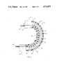
As shown in FIG. 2, the distal end of theinsertion tube 12 includes the noted viewing head 11 that is secured to thesteering unit 17. The steering unit is formed by a series offlat washers 27--27 that are stacked in a face-to-face relationship within theflexible sheath 28 of the insertion tube. Two pairs of steering cables, depicted as 29 and 30, are passed through suitable openings in the washers. Each cable is anchored at one end in the back of the viewing head and is attached to a suitable mechanism connected to the control knobs so that each cable has two opposed runs passing through the stack. Hemispherical-shaped beads 32--32 are disposed over the cables within the spaces separating the washers. The flat face of each bead rests against the end face of a washer while the spherical face of the bead rides in rolling contact with the spherical face of a companion bead to form a hinge set. Two hinge sets are positioned in the space separating the adjacent washers with the two sets being mounted on the opposed runs of the same cable. The hinge sets are mounted on opposite cables in alternate spaces so that the steering unit can be bent in two distinct lanes that are generally 90 degrees apart. As can be seen by manipulating the control knobs, the viewing head can be precisely turned about 180 degrees in a very tight radius.
As noted, the stacked washers in the steering unit are covered withflexible sheath 28 that forms the outer liner of the insertion tube. Each washer contains a central passage that allows various system-related components to freely pass through the steering section. These may include a light transmitting fiber bundle, video-related leads to and from the image sensor assembly and a biopsy channel for providing tool access to a target in the viewing region of the head. For the sake of clarity only, thebiopsy channel 39 is shown in FIG. 2. The biopsy channel extends the full length of the insertion tube and opens into the target region through thefront face 41 of the viewing head. The proximal end of the channel extends into the control housing and is coupled to a luer lock connecter (not shown) which, in turn, is closed by a penetratable seal 42 (FIG. 1) at the back of the housing. Abiopsy forcep 43, which is mounted upon the distal end of aflexible probe 44, is shown in FIG. 2 extended through the viewing head into the target region where it can take a tissue sample. Theprobe 44 is a hollow wound wire cable having anactuator wire 46 passing axially along its length for opening and closing the forceps. Although a biopsy forcep is shown in the present embodiment of the invention, it should be understood that any suitable tool as shown and used in the art can be used in the present invention.
Because the biopsy channel passes through the steering unit of the insertion tube, it will at certain times be subjected to severe bending and/or twisting as the head is being manipulated to maneuver or position the viewing head. These actions, alone or in combination, can restrict or even close the channel opening and thus prevent passage of a tool through this critical region. As will be explained below, the present biopsy channel is reinforced at least along the length of tubing that passes through the steering unit so that it resists both bending and torsional stress that might normally collapse or close off the biopsy channel opening.
FIG. 3 is a partial view of abiopsy channel 39 embodying the present invention. The channel includes a fronttubular section 47 that is bonded atseam 48 by any suitable means to a complementary reartubular section 49. Thefront section 47, in assembly, is situated inside the steering section and viewing head of the insertion tube and therefore exposed to higher stressing than the remainder of the channel. The front section is formed of a flexible thermoplastictubular substrate 50, that is preferably a heat softenable vinyl material. A knitted or braidedfabric 51 of open mesh construction encircles the front section of the channel and is thermally bonded to the tubing so that the fiber strands are at least partially and preferably fully embedded beneath the outer periphery of the tubing. Therear section 49 of the channel is formed from a single piece of stiffer plastic tubing, preferably Teflon, which passes back through the insertion tube into the control housing. The Teflon and vinyl tube sections coact to provide a highly lubricious channel through which a tool, such as a biopsy forceps, will freely slide as it is moved into or out of the target region of the instrument.
Turning now to FIG. 4 there is shown an extrusion die 56 used in the fabrication of the reinforcedfront section 47 of the channel. Initially, the heatsoftenable thermoplastic substrate 50 is passed over acylindrical mandrel 55. A close running fit is provided between the inside diameter of the tubing and the outside diameter of the mandrel so that the tubing is snugly seated on the mandrel. A knitted wire fabric similar to that used for shielding electrical cable is slipped over the tubing. The fabric is preferably cylindrical in form and contains an open weave which is used in many well known braids or weaves conventionally used in the art. One such fabric is described in U.S. Pat. No. 4,375,009. The fabric strands are woven so that the cylinder can be stretched axially while correspondingly reduced in diameter to accommodate for differences in tube sizes.
The mandrel, the tubing and the knitted fabric are drawn, as an assembly, through aheated die 56 having acircular opening 60 formed therein. A series of internalelectrical heating elements 59--59 are disposed throughout the die for raising the temperature at the die opening to a level sufficient to soften the outer portion of the tube passing therethrough. The heating elements are connected by leads to a suitable supply of electrical energy (not shown). The diameter of thedie opening 60 is set for the desired outside diameter of the biopsy channel which, in practice, is slightly less than the outside diameter of the thermoplastic tubing.
The entrance to the die opening has an expandedmouth 62 that guides the tubing and the reinforcing fabric into the opening. As the tubing is drawn into the die opening, the outer surface of the tubing is thermally softened so that the reinforcing fabric is forced inwardly into the softened material. At the same time, the displaced substrate material is forced outwardly through the mesh openings between the fabric strands thereby filling the mesh openings and embedding the wire in the tube. The reinforcing fabric and the tubing are both compressed slightly by the die into a composite structure with the fabric being either partially or completely embedded in the tube. Preferably, the fabric is embedded below the surface of the thermoplastic so that a low friction lubricious surface is presented to objects inside the insertion tube that it might come in contact with.
Upon removal from the mandrel, the reinforced section is joined to the stiffer rear section of the biopsy channel to complete the biopsy channel. The reinforced section is mounted within the insertion tube as shown in FIG. 2 so that it is situated inside the steering unit. The knitted wire fabric, because of its ability to stretch axially, permits the biopsy channel to follow the insertion tube through a small radius bend without collapsing or otherwise losing its circular configuration in the critical bend region. The fabric furthermore supports the reinforced section to prevent the tube from being torsionally deformed under stress.
Although the present invention has been described with reference to a two piece biopsy channel, it should be understood that the invention is not limited to a specific configuration. For example, the channel can be constructed from a single piece of heat softenable tubing having reinforcing fabric embedded only within that section that transcends the steering unit. In certain cases, it may be important to extend the fabric along the entire length of the channel. In any event, the biopsy channel of the invention will contain an open mesh fabric embedded in the tubular substrate in regions that are subjected to severe bending to insure that the channel opening will not collapse during bending thus rendering the channel unusable for its intended purpose.
While this invention has been described in detail with respect to a preferred embodiment, it should be understood that this invention is not limited to that embodiment, and that many modifications and variations thereof could be effected by those skilled in the art without departure from the scope and spirit of this invention, as defined in the appended claims.
Claims (4)
1. An endoscope including an insertion tube that is connected at its proximal end to a control housing and having a bendable steering unit for maneuvering a viewing head located at the distal end of the tube, the steering unit being located near the distal end of the insertion tube adjacent the viewing head, said endoscope further including
a lubricious biopsy channel passing through the inside of the insertion tube having a first tubular section contained within the steering unit that is joined to a second tubular section that passes back into the control housing,
said first section being formed of a bendable heat softenable thermoplastic material that is encircled by open mesh metal fabric,
said second section being formed of a stiffer plastic material that has a greater resistance to bending than the first section, and
the open mesh metal fabric having fibers that are at least partially embedded in the outer surface of the first section for reinforcing said section to prevent the section from closing when bent to a small radius.
2. The endoscope of claim 1 wherein said first section is formed of vinyl and the second section is formed of Teflon.
3. Th endoscope of claim 1 wherein the metal fabric is woven into a cylinder that substantially encloses the first section of the biopsy channel.
4. The endoscope of claim 1 wherein the strands of the metal fabric are completely embedded beneath the outer surface of the first section.
Priority Applications (1)
| Application Number | Priority Date | Filing Date | Title |
|---|---|---|---|
| US06/828,134US4714075A (en) | 1986-02-10 | 1986-02-10 | Biopsy channel for endoscope |
Applications Claiming Priority (1)
| Application Number | Priority Date | Filing Date | Title |
|---|---|---|---|
| US06/828,134US4714075A (en) | 1986-02-10 | 1986-02-10 | Biopsy channel for endoscope |
Publications (1)
| Publication Number | Publication Date |
|---|---|
| US4714075Atrue US4714075A (en) | 1987-12-22 |
Family
ID=25250997
Family Applications (1)
| Application Number | Title | Priority Date | Filing Date |
|---|---|---|---|
| US06/828,134Expired - LifetimeUS4714075A (en) | 1986-02-10 | 1986-02-10 | Biopsy channel for endoscope |
Country Status (1)
| Country | Link |
|---|---|
| US (1) | US4714075A (en) |
Cited By (59)
| Publication number | Priority date | Publication date | Assignee | Title |
|---|---|---|---|---|
| US4836189A (en)* | 1988-07-27 | 1989-06-06 | Welch Allyn, Inc. | Video hysteroscope |
| US4877016A (en)* | 1988-07-29 | 1989-10-31 | Kantor Edward A | Video endoscopic microscope |
| US4932394A (en)* | 1987-08-10 | 1990-06-12 | Kabushiki Kaisha Toshiba | Endoscope including scope terminal locking indicator |
| GB2226245A (en)* | 1988-11-18 | 1990-06-27 | Alan Crockard | Endoscope, remote actuator and aneurysm clip applicator. |
| DE4013653A1 (en)* | 1989-05-01 | 1990-11-08 | Machida Endoscope Co Ltd | ENDOSCOPE |
| US5015249A (en)* | 1989-12-26 | 1991-05-14 | Nakao Naomi L | Endoscopic stapling device and method |
| US5049153A (en)* | 1989-12-26 | 1991-09-17 | Nakao Naomi L | Endoscopic stapling device and method |
| WO1992001414A1 (en)* | 1990-07-20 | 1992-02-06 | W.L. Gore & Associates, Inc. | Invasive probe system |
| US5156609A (en)* | 1989-12-26 | 1992-10-20 | Nakao Naomi L | Endoscopic stapling device and method |
| US5222961A (en)* | 1989-12-26 | 1993-06-29 | Naomi Nakao | Endoscopic stapling device and related staple |
| US5329940A (en)* | 1990-02-14 | 1994-07-19 | Adair Edwin Lloyd | Endotracheal tube intubation assist device |
| US5407630A (en)* | 1989-03-21 | 1995-04-18 | Insituform (Netherlands) Bv | Lining of pipelines or passageways |
| EP0501648B1 (en)* | 1991-02-27 | 1997-10-22 | Electric Power Research Institute, Inc | In bundle foreign object search and retrieval apparatus |
| US5842971A (en)* | 1996-05-22 | 1998-12-01 | Yoon; Inbae | Optical endoscopic portals and methods of using the same to establish passages through cavity walls |
| US5885207A (en)* | 1996-11-01 | 1999-03-23 | Asahi Kogaku Kogyo Kabushiki Kaisha | Flexible tube of endoscope |
| US5938587A (en)* | 1996-04-25 | 1999-08-17 | Modified Polymer Components, Inc. | Flexible inner liner for the working channel of an endoscope |
| US6200311B1 (en) | 1998-01-20 | 2001-03-13 | Eclipse Surgical Technologies, Inc. | Minimally invasive TMR device |
| US6273903B1 (en) | 1999-11-08 | 2001-08-14 | Peter J. Wilk | Endoscopic stapling device and related staple |
| US6494886B1 (en) | 2000-06-22 | 2002-12-17 | Granit Medical Innovation, Inc. | Off-set clamp mechanism and associated method for minimally invasive surgery |
| WO2003057019A1 (en) | 2002-01-04 | 2003-07-17 | Vision Sciences, Inc. | Endoscope channel with reduced bending resistance. |
| US20030236549A1 (en)* | 2000-07-21 | 2003-12-25 | Frank Bonadio | Surgical instrument |
| US20040059253A1 (en)* | 2002-01-04 | 2004-03-25 | Stephen Martone | Endoscope sheath assemblies having an attached biopsy sampling device |
| US20040092978A1 (en)* | 2002-04-15 | 2004-05-13 | Surti Vihar C. | Clip device |
| US20050070754A1 (en)* | 2003-09-29 | 2005-03-31 | Rudolph Nobis | Actuation mechanism for flexible endoscopic device |
| US20050234512A1 (en)* | 2004-04-19 | 2005-10-20 | Nakao Naomi L | Endoscopic anchoring device and associated method |
| US20060069311A1 (en)* | 2004-09-30 | 2006-03-30 | Roy Sullivan | Manually controlled endoscope |
| US20070088319A1 (en)* | 2003-09-18 | 2007-04-19 | Vison-Sciences, Inc. | Braided minimally invasive channel |
| US7241263B2 (en) | 2004-09-30 | 2007-07-10 | Scimed Life Systems, Inc. | Selectively rotatable shaft coupler |
| US20070225078A1 (en)* | 2006-03-23 | 2007-09-27 | Wms Gaming Inc. | Gaming machine with modular actuator for remote door latch |
| US20080015416A1 (en)* | 2006-07-14 | 2008-01-17 | Wilson-Cook Medical, Inc | Papilla spreader |
| US7413543B2 (en) | 2003-04-01 | 2008-08-19 | Scimed Life Systems, Inc. | Endoscope with actively cooled illumination sources |
| US7479106B2 (en) | 2004-09-30 | 2009-01-20 | Boston Scientific Scimed, Inc. | Automated control of irrigation and aspiration in a single-use endoscope |
| US7578786B2 (en) | 2003-04-01 | 2009-08-25 | Boston Scientific Scimed, Inc. | Video endoscope |
| US7591783B2 (en) | 2003-04-01 | 2009-09-22 | Boston Scientific Scimed, Inc. | Articulation joint for video endoscope |
| US7597662B2 (en) | 2004-09-30 | 2009-10-06 | Boston Scientific Scimed, Inc. | Multi-fluid delivery system |
| US20090275857A1 (en)* | 2007-01-17 | 2009-11-05 | G.I. View Ltd. | Diagnostic or treatment tool for colonoscopy |
| US20100016873A1 (en)* | 2006-12-05 | 2010-01-21 | Gayzik Caroline M | Combination therapy hemostatic clip |
| US7846107B2 (en) | 2005-05-13 | 2010-12-07 | Boston Scientific Scimed, Inc. | Endoscopic apparatus with integrated multiple biopsy device |
| US7955255B2 (en) | 2006-04-20 | 2011-06-07 | Boston Scientific Scimed, Inc. | Imaging assembly with transparent distal cap |
| US7967759B2 (en) | 2006-01-19 | 2011-06-28 | Boston Scientific Scimed, Inc. | Endoscopic system with integrated patient respiratory status indicator |
| US8052597B2 (en) | 2005-08-30 | 2011-11-08 | Boston Scientific Scimed, Inc. | Method for forming an endoscope articulation joint |
| US8083671B2 (en) | 2004-09-30 | 2011-12-27 | Boston Scientific Scimed, Inc. | Fluid delivery system for use with an endoscope |
| US8097003B2 (en) | 2005-05-13 | 2012-01-17 | Boston Scientific Scimed, Inc. | Endoscopic apparatus with integrated variceal ligation device |
| US8118732B2 (en) | 2003-04-01 | 2012-02-21 | Boston Scientific Scimed, Inc. | Force feedback control system for video endoscope |
| US8199187B2 (en) | 2004-09-30 | 2012-06-12 | Boston Scientific Scimed, Inc. | Adapter for use with digital imaging medical device |
| US8202265B2 (en) | 2006-04-20 | 2012-06-19 | Boston Scientific Scimed, Inc. | Multiple lumen assembly for use in endoscopes or other medical devices |
| US20120296168A1 (en)* | 2003-01-29 | 2012-11-22 | Horne Jr Guy E | Composite Flexible Endoscope Insertion Shaft With Tubular Substructure |
| US20120323070A1 (en)* | 2004-11-23 | 2012-12-20 | Intuitive Surgical Operations, Inc. | Instrument Systems and Methods of Use |
| US8353860B2 (en) | 2004-09-30 | 2013-01-15 | Boston Scientific Scimed, Inc. | Device for obstruction removal with specific tip structure |
| US8357148B2 (en) | 2004-09-30 | 2013-01-22 | Boston Scientific Scimed, Inc. | Multi-functional endoscopic system for use in electrosurgical applications |
| US8419720B1 (en) | 2012-02-07 | 2013-04-16 | National Advanced Endoscopy Devices, Incorporated | Flexible laparoscopic device |
| US8535219B2 (en) | 2003-04-01 | 2013-09-17 | Boston Scientific Scimed, Inc. | Fluid manifold for endoscope system |
| US8764774B2 (en) | 2010-11-09 | 2014-07-01 | Cook Medical Technologies Llc | Clip system having tether segments for closure |
| US8888684B2 (en) | 2006-03-27 | 2014-11-18 | Boston Scientific Scimed, Inc. | Medical devices with local drug delivery capabilities |
| US20160310043A1 (en)* | 2015-04-26 | 2016-10-27 | Endochoice, Inc. | Endoscopic Polyp Measurement Tool and Method for Using the Same |
| US9713465B1 (en) | 2004-04-19 | 2017-07-25 | Granit Medical Innovation Llc | Surgical closure device and associated method |
| CN110897592A (en)* | 2019-12-31 | 2020-03-24 | 湖南省华芯医疗器械有限公司 | Endoscope instrument channel tube and endoscope for preventing collapse during bending |
| WO2020094191A1 (en)* | 2018-11-07 | 2020-05-14 | Richard Wolf Gmbh | Endoscopic instrument |
| DE102021126571A1 (en) | 2021-10-13 | 2023-04-13 | Ambu A/S | Reinforced working channel tubing for an endoscope |
Citations (7)
| Publication number | Priority date | Publication date | Assignee | Title |
|---|---|---|---|---|
| US3470876A (en)* | 1966-09-28 | 1969-10-07 | John Barchilon | Dirigible catheter |
| US3670721A (en)* | 1970-02-05 | 1972-06-20 | Olympus Optical Co | Endoscope |
| US3960143A (en)* | 1973-08-31 | 1976-06-01 | Olympus Optical Co., Ltd. | Endoscope with a tube for a medical treating instrument |
| US3998216A (en)* | 1973-10-04 | 1976-12-21 | Olympus Optical Co., Ltd. | Bending tube for endoscope |
| US4245624A (en)* | 1977-01-20 | 1981-01-20 | Olympus Optical Co., Ltd. | Endoscope with flexible tip control |
| US4327711A (en)* | 1979-11-16 | 1982-05-04 | Olympus Optical Co., Ltd. | Flexible tube for an endoscope |
| DE3242449A1 (en)* | 1981-11-17 | 1983-05-26 | Kabushiki Kaisha Medos Kenkyusho, Tokyo | FLEXIBLE TUBE FOR AN ENDOSCOPE AND METHOD FOR PRODUCING THIS TUBE |
- 1986
- 1986-02-10USUS06/828,134patent/US4714075A/ennot_activeExpired - Lifetime
Patent Citations (7)
| Publication number | Priority date | Publication date | Assignee | Title |
|---|---|---|---|---|
| US3470876A (en)* | 1966-09-28 | 1969-10-07 | John Barchilon | Dirigible catheter |
| US3670721A (en)* | 1970-02-05 | 1972-06-20 | Olympus Optical Co | Endoscope |
| US3960143A (en)* | 1973-08-31 | 1976-06-01 | Olympus Optical Co., Ltd. | Endoscope with a tube for a medical treating instrument |
| US3998216A (en)* | 1973-10-04 | 1976-12-21 | Olympus Optical Co., Ltd. | Bending tube for endoscope |
| US4245624A (en)* | 1977-01-20 | 1981-01-20 | Olympus Optical Co., Ltd. | Endoscope with flexible tip control |
| US4327711A (en)* | 1979-11-16 | 1982-05-04 | Olympus Optical Co., Ltd. | Flexible tube for an endoscope |
| DE3242449A1 (en)* | 1981-11-17 | 1983-05-26 | Kabushiki Kaisha Medos Kenkyusho, Tokyo | FLEXIBLE TUBE FOR AN ENDOSCOPE AND METHOD FOR PRODUCING THIS TUBE |
Cited By (97)
| Publication number | Priority date | Publication date | Assignee | Title |
|---|---|---|---|---|
| US4932394A (en)* | 1987-08-10 | 1990-06-12 | Kabushiki Kaisha Toshiba | Endoscope including scope terminal locking indicator |
| US4836189A (en)* | 1988-07-27 | 1989-06-06 | Welch Allyn, Inc. | Video hysteroscope |
| US4877016A (en)* | 1988-07-29 | 1989-10-31 | Kantor Edward A | Video endoscopic microscope |
| US5174276A (en)* | 1988-11-18 | 1992-12-29 | Hillway Surgical Limited | Endoscope device for applying an aneurysm clip |
| GB2226245A (en)* | 1988-11-18 | 1990-06-27 | Alan Crockard | Endoscope, remote actuator and aneurysm clip applicator. |
| US5407630A (en)* | 1989-03-21 | 1995-04-18 | Insituform (Netherlands) Bv | Lining of pipelines or passageways |
| DE4013653A1 (en)* | 1989-05-01 | 1990-11-08 | Machida Endoscope Co Ltd | ENDOSCOPE |
| US5156609A (en)* | 1989-12-26 | 1992-10-20 | Nakao Naomi L | Endoscopic stapling device and method |
| US5222961A (en)* | 1989-12-26 | 1993-06-29 | Naomi Nakao | Endoscopic stapling device and related staple |
| US5049153A (en)* | 1989-12-26 | 1991-09-17 | Nakao Naomi L | Endoscopic stapling device and method |
| US5015249A (en)* | 1989-12-26 | 1991-05-14 | Nakao Naomi L | Endoscopic stapling device and method |
| US5329940A (en)* | 1990-02-14 | 1994-07-19 | Adair Edwin Lloyd | Endotracheal tube intubation assist device |
| US5158086A (en)* | 1990-07-20 | 1992-10-27 | W. L. Gore & Associates, Inc. | Invasive probe system |
| WO1992001414A1 (en)* | 1990-07-20 | 1992-02-06 | W.L. Gore & Associates, Inc. | Invasive probe system |
| EP0501648B1 (en)* | 1991-02-27 | 1997-10-22 | Electric Power Research Institute, Inc | In bundle foreign object search and retrieval apparatus |
| US5938587A (en)* | 1996-04-25 | 1999-08-17 | Modified Polymer Components, Inc. | Flexible inner liner for the working channel of an endoscope |
| US5842971A (en)* | 1996-05-22 | 1998-12-01 | Yoon; Inbae | Optical endoscopic portals and methods of using the same to establish passages through cavity walls |
| US5885207A (en)* | 1996-11-01 | 1999-03-23 | Asahi Kogaku Kogyo Kabushiki Kaisha | Flexible tube of endoscope |
| US6200311B1 (en) | 1998-01-20 | 2001-03-13 | Eclipse Surgical Technologies, Inc. | Minimally invasive TMR device |
| US6273903B1 (en) | 1999-11-08 | 2001-08-14 | Peter J. Wilk | Endoscopic stapling device and related staple |
| US6494886B1 (en) | 2000-06-22 | 2002-12-17 | Granit Medical Innovation, Inc. | Off-set clamp mechanism and associated method for minimally invasive surgery |
| US20030236549A1 (en)* | 2000-07-21 | 2003-12-25 | Frank Bonadio | Surgical instrument |
| US8157817B2 (en) | 2000-07-21 | 2012-04-17 | Atropos Limited | Surgical instrument |
| US20060079735A1 (en)* | 2002-01-04 | 2006-04-13 | Stephen Martone | Endoscope assemblies having working channels with reduced bending and stretching resistance |
| WO2003057019A1 (en) | 2002-01-04 | 2003-07-17 | Vision Sciences, Inc. | Endoscope channel with reduced bending resistance. |
| US20040059253A1 (en)* | 2002-01-04 | 2004-03-25 | Stephen Martone | Endoscope sheath assemblies having an attached biopsy sampling device |
| US20040193007A1 (en)* | 2002-01-04 | 2004-09-30 | Stephen Martone | Endoscope assemblies having working channels with reduced bending and stretching resistance |
| US7081097B2 (en) | 2002-01-04 | 2006-07-25 | Vision Sciences, Inc. | Endoscope sheath assemblies having an attached biopsy sampling device |
| US7056284B2 (en) | 2002-01-04 | 2006-06-06 | Vision Sciences, Inc. | Endoscope assemblies having working channels with reduced bending and stretching resistance |
| US20040092978A1 (en)* | 2002-04-15 | 2004-05-13 | Surti Vihar C. | Clip device |
| US7122041B2 (en) | 2002-04-15 | 2006-10-17 | Wilson-Cook Medical Inc. | Clip device |
| US20120296168A1 (en)* | 2003-01-29 | 2012-11-22 | Horne Jr Guy E | Composite Flexible Endoscope Insertion Shaft With Tubular Substructure |
| US8535219B2 (en) | 2003-04-01 | 2013-09-17 | Boston Scientific Scimed, Inc. | Fluid manifold for endoscope system |
| US7591783B2 (en) | 2003-04-01 | 2009-09-22 | Boston Scientific Scimed, Inc. | Articulation joint for video endoscope |
| US11324395B2 (en) | 2003-04-01 | 2022-05-10 | Boston Scientific Scimed, Inc. | Endoscopic imaging system |
| US10765307B2 (en) | 2003-04-01 | 2020-09-08 | Boston Scientific Scimed, Inc. | Endoscopic imaging system |
| US9913573B2 (en) | 2003-04-01 | 2018-03-13 | Boston Scientific Scimed, Inc. | Endoscopic imaging system |
| US7413543B2 (en) | 2003-04-01 | 2008-08-19 | Scimed Life Systems, Inc. | Endoscope with actively cooled illumination sources |
| US8425408B2 (en) | 2003-04-01 | 2013-04-23 | Boston Scientific Scimed, Inc. | Articulation joint for video endoscope |
| US8622894B2 (en) | 2003-04-01 | 2014-01-07 | Boston Scientific Scimed, Inc. | Articulation joint |
| US7578786B2 (en) | 2003-04-01 | 2009-08-25 | Boston Scientific Scimed, Inc. | Video endoscope |
| US8118732B2 (en) | 2003-04-01 | 2012-02-21 | Boston Scientific Scimed, Inc. | Force feedback control system for video endoscope |
| US8608648B2 (en) | 2003-04-01 | 2013-12-17 | Boston Scientific Scimed, Inc. | Articulation joint |
| US8475366B2 (en) | 2003-04-01 | 2013-07-02 | Boston Scientific Scimed, Inc. | Articulation joint for a medical device |
| US20070088319A1 (en)* | 2003-09-18 | 2007-04-19 | Vison-Sciences, Inc. | Braided minimally invasive channel |
| US20050070754A1 (en)* | 2003-09-29 | 2005-03-31 | Rudolph Nobis | Actuation mechanism for flexible endoscopic device |
| US7708756B2 (en)* | 2003-09-29 | 2010-05-04 | Ethicon Endo-Surgery, Inc. | Actuation mechanism for flexible endoscopic device |
| US20100174311A1 (en)* | 2003-09-29 | 2010-07-08 | Rudolph Nobis | Actuation Apparatus and Method |
| US9713465B1 (en) | 2004-04-19 | 2017-07-25 | Granit Medical Innovation Llc | Surgical closure device and associated method |
| US7833238B2 (en) | 2004-04-19 | 2010-11-16 | Granit Medical Innovations, Llc | Endoscopic anchoring device and associated method |
| US20050234512A1 (en)* | 2004-04-19 | 2005-10-20 | Nakao Naomi L | Endoscopic anchoring device and associated method |
| US8357148B2 (en) | 2004-09-30 | 2013-01-22 | Boston Scientific Scimed, Inc. | Multi-functional endoscopic system for use in electrosurgical applications |
| US7479106B2 (en) | 2004-09-30 | 2009-01-20 | Boston Scientific Scimed, Inc. | Automated control of irrigation and aspiration in a single-use endoscope |
| US7241263B2 (en) | 2004-09-30 | 2007-07-10 | Scimed Life Systems, Inc. | Selectively rotatable shaft coupler |
| US8083671B2 (en) | 2004-09-30 | 2011-12-27 | Boston Scientific Scimed, Inc. | Fluid delivery system for use with an endoscope |
| USRE46007E1 (en) | 2004-09-30 | 2016-05-24 | Boston Scientific Scimed, Inc. | Automated control of irrigation and aspiration in a single-use endoscope |
| US7597662B2 (en) | 2004-09-30 | 2009-10-06 | Boston Scientific Scimed, Inc. | Multi-fluid delivery system |
| US8435172B2 (en) | 2004-09-30 | 2013-05-07 | Boston Scientific Scimed, Inc. | Automated control of irrigation and aspiration in a single-use endoscope |
| US20060069311A1 (en)* | 2004-09-30 | 2006-03-30 | Roy Sullivan | Manually controlled endoscope |
| US8197400B2 (en) | 2004-09-30 | 2012-06-12 | Boston Scientific Scimed, Inc. | Selectively rotatable shaft coupler |
| US8199187B2 (en) | 2004-09-30 | 2012-06-12 | Boston Scientific Scimed, Inc. | Adapter for use with digital imaging medical device |
| US7789826B2 (en) | 2004-09-30 | 2010-09-07 | Boston Scientific Scimed, Inc. | Manually controlled endoscope |
| US20110105844A1 (en)* | 2004-09-30 | 2011-05-05 | Boston Scientific Scimed | Manually controlled endoscope |
| US8366607B2 (en) | 2004-09-30 | 2013-02-05 | Boston Scientific Scimed, Inc. | Manually controlled endoscope |
| US8353860B2 (en) | 2004-09-30 | 2013-01-15 | Boston Scientific Scimed, Inc. | Device for obstruction removal with specific tip structure |
| US9155449B2 (en)* | 2004-11-23 | 2015-10-13 | Intuitive Surgical Operations Inc. | Instrument systems and methods of use |
| US20120323070A1 (en)* | 2004-11-23 | 2012-12-20 | Intuitive Surgical Operations, Inc. | Instrument Systems and Methods of Use |
| US8097003B2 (en) | 2005-05-13 | 2012-01-17 | Boston Scientific Scimed, Inc. | Endoscopic apparatus with integrated variceal ligation device |
| US8585715B2 (en) | 2005-05-13 | 2013-11-19 | Boston Scientific Scimed, Inc. | Endoscopic apparatus with integrated variceal ligation device |
| US7846107B2 (en) | 2005-05-13 | 2010-12-07 | Boston Scientific Scimed, Inc. | Endoscopic apparatus with integrated multiple biopsy device |
| US9439557B2 (en) | 2005-08-30 | 2016-09-13 | Boston Scientific Scimed, Inc. | Articulation joint |
| US11957312B2 (en) | 2005-08-30 | 2024-04-16 | Boston Scientific Scimed, Inc. | Method for forming an endoscope articulation joint |
| US8052597B2 (en) | 2005-08-30 | 2011-11-08 | Boston Scientific Scimed, Inc. | Method for forming an endoscope articulation joint |
| US11191424B2 (en) | 2005-08-30 | 2021-12-07 | Boston Scientific Scimed, Inc. | Method for forming an endoscope articulation joint |
| US10052013B2 (en) | 2005-08-30 | 2018-08-21 | Boston Scientific Scimed, Inc. | Medical device comprising segments |
| US7967759B2 (en) | 2006-01-19 | 2011-06-28 | Boston Scientific Scimed, Inc. | Endoscopic system with integrated patient respiratory status indicator |
| US7553237B2 (en)* | 2006-03-23 | 2009-06-30 | Wms Gaming Inc. | Gaming machine with modular actuator for remote door latch |
| US20070225078A1 (en)* | 2006-03-23 | 2007-09-27 | Wms Gaming Inc. | Gaming machine with modular actuator for remote door latch |
| US8888684B2 (en) | 2006-03-27 | 2014-11-18 | Boston Scientific Scimed, Inc. | Medical devices with local drug delivery capabilities |
| US8202265B2 (en) | 2006-04-20 | 2012-06-19 | Boston Scientific Scimed, Inc. | Multiple lumen assembly for use in endoscopes or other medical devices |
| US7955255B2 (en) | 2006-04-20 | 2011-06-07 | Boston Scientific Scimed, Inc. | Imaging assembly with transparent distal cap |
| US8870753B2 (en) | 2006-04-20 | 2014-10-28 | Boston Scientific Scimed, Inc. | Imaging assembly with transparent distal cap |
| US9358363B2 (en) | 2006-04-20 | 2016-06-07 | Boston Scientific Scimed, Inc. | Multiple lumen assembly for use in endoscopes or other medical devices |
| US8425412B2 (en) | 2006-07-14 | 2013-04-23 | Cook Medical Technologies Llc | Papilla spreader |
| US20080015416A1 (en)* | 2006-07-14 | 2008-01-17 | Wilson-Cook Medical, Inc | Papilla spreader |
| US8152822B2 (en) | 2006-12-05 | 2012-04-10 | Cook Medical Technologies Llc | Combination therapy hemostatic clip |
| US20100016873A1 (en)* | 2006-12-05 | 2010-01-21 | Gayzik Caroline M | Combination therapy hemostatic clip |
| US8876730B2 (en) | 2007-01-17 | 2014-11-04 | G. I. View Ltd. | Diagnostic or treatment tool for colonoscopy |
| US20090275857A1 (en)* | 2007-01-17 | 2009-11-05 | G.I. View Ltd. | Diagnostic or treatment tool for colonoscopy |
| US8764774B2 (en) | 2010-11-09 | 2014-07-01 | Cook Medical Technologies Llc | Clip system having tether segments for closure |
| US8419720B1 (en) | 2012-02-07 | 2013-04-16 | National Advanced Endoscopy Devices, Incorporated | Flexible laparoscopic device |
| US20160310043A1 (en)* | 2015-04-26 | 2016-10-27 | Endochoice, Inc. | Endoscopic Polyp Measurement Tool and Method for Using the Same |
| WO2020094191A1 (en)* | 2018-11-07 | 2020-05-14 | Richard Wolf Gmbh | Endoscopic instrument |
| CN110897592A (en)* | 2019-12-31 | 2020-03-24 | 湖南省华芯医疗器械有限公司 | Endoscope instrument channel tube and endoscope for preventing collapse during bending |
| WO2021136418A1 (en)* | 2019-12-31 | 2021-07-08 | 湖南省华芯医疗器械有限公司 | Endoscopic instrument channel tube that avoids collapsing during bending, and endoscope |
| DE102021126571A1 (en) | 2021-10-13 | 2023-04-13 | Ambu A/S | Reinforced working channel tubing for an endoscope |
| EP4166059A1 (en) | 2021-10-13 | 2023-04-19 | Ambu A/S | Reinforced working channel tube for an endoscope |
Similar Documents
| Publication | Publication Date | Title |
|---|---|---|
| US4714075A (en) | Biopsy channel for endoscope | |
| US4899732A (en) | Miniscope | |
| US3739770A (en) | Bendable tube of an endoscope | |
| US4676229A (en) | Biopsy channel for an endoscope | |
| US6984203B2 (en) | Endoscope with adjacently positioned guiding apparatus | |
| US6800056B2 (en) | Endoscope with guiding apparatus | |
| US6740030B2 (en) | Endoscope assemblies having working channels with reduced bending and stretching resistance | |
| US4745908A (en) | Inspection instrument fexible shaft having deflection compensation means | |
| US5299562A (en) | Endoscope having a controllable distal end piece | |
| EP1487318B1 (en) | Endoscope with guiding apparatus | |
| US4697576A (en) | Endoscope forceps elevator cable seal | |
| JPH01313038A (en) | Endoscope used along with disposable sheath | |
| US4871229A (en) | Method for assembling optical fiber bundles in an endoscope | |
| CN112788977B (en) | Endoscope bending part and endoscope | |
| JP3923701B2 (en) | Endoscope | |
| JP2022533178A (en) | Pull cable management for maneuverable catheters | |
| JPH0561605B2 (en) | ||
| JP2000185013A (en) | Endoscope | |
| JP3756874B2 (en) | Endoscope | |
| EP4355190B1 (en) | An endoscope | |
| US11304594B2 (en) | Articulating medical device | |
| JP3970057B2 (en) | Endoscope | |
| JP5996307B2 (en) | Endoscope | |
| JPH1099264A (en) | Endoscope | |
| JP4241969B2 (en) | Endoscope |
Legal Events
| Date | Code | Title | Description |
|---|---|---|---|
| AS | Assignment | Owner name:WELCH ALLYN, INC., 4341 STATE STREET RD., SKANEATE Free format text:ASSIGNMENT OF ASSIGNORS INTEREST.;ASSIGNORS:KRAUTER, ALLAN I.;VIVENZIO, ROBERT L.;REEL/FRAME:004552/0259 Effective date:19860204 Owner name:WELCH ALLYN, INC., NEW YORK Free format text:ASSIGNMENT OF ASSIGNORS INTEREST;ASSIGNORS:KRAUTER, ALLAN I.;VIVENZIO, ROBERT L.;REEL/FRAME:004552/0259 Effective date:19860204 | |
| STCF | Information on status: patent grant | Free format text:PATENTED CASE | |
| FPAY | Fee payment | Year of fee payment:4 | |
| FEPP | Fee payment procedure | Free format text:PAYOR NUMBER ASSIGNED (ORIGINAL EVENT CODE: ASPN); ENTITY STATUS OF PATENT OWNER: LARGE ENTITY | |
| FPAY | Fee payment | Year of fee payment:8 | |
| FPAY | Fee payment | Year of fee payment:12 |