US4713880A - Lead making machine - Google Patents
Lead making machineDownload PDFInfo
- Publication number
- US4713880A US4713880AUS07/024,887US2488787AUS4713880AUS 4713880 AUS4713880 AUS 4713880AUS 2488787 AUS2488787 AUS 2488787AUS 4713880 AUS4713880 AUS 4713880A
- Authority
- US
- United States
- Prior art keywords
- wire
- lead
- stripped
- gripping means
- cutting
- Prior art date
- Legal status (The legal status is an assumption and is not a legal conclusion. Google has not performed a legal analysis and makes no representation as to the accuracy of the status listed.)
- Expired - Fee Related
Links
- 238000009413insulationMethods0.000claimsabstractdescription19
- 238000007689inspectionMethods0.000claimsabstractdescription8
- 230000033001locomotionEffects0.000claimsdescription7
- 230000005484gravityEffects0.000claimsdescription3
- 230000003287optical effectEffects0.000claimsdescription3
- 238000011179visual inspectionMethods0.000claims2
- 239000002184metalSubstances0.000description2
- NJPPVKZQTLUDBO-UHFFFAOYSA-NnovaluronChemical compoundC1=C(Cl)C(OC(F)(F)C(OC(F)(F)F)F)=CC=C1NC(=O)NC(=O)C1=C(F)C=CC=C1FNJPPVKZQTLUDBO-UHFFFAOYSA-N0.000description2
- 230000035939shockEffects0.000description2
- 238000005452bendingMethods0.000description1
- 230000005540biological transmissionEffects0.000description1
- 238000010276constructionMethods0.000description1
- 230000000694effectsEffects0.000description1
- 238000003780insertionMethods0.000description1
- 230000037431insertionEffects0.000description1
- 230000007257malfunctionEffects0.000description1
- 230000000284resting effectEffects0.000description1
- 238000005476solderingMethods0.000description1
- 230000007723transport mechanismEffects0.000description1
- 239000002699waste materialSubstances0.000description1
Images


Classifications
- H—ELECTRICITY
- H01—ELECTRIC ELEMENTS
- H01R—ELECTRICALLY-CONDUCTIVE CONNECTIONS; STRUCTURAL ASSOCIATIONS OF A PLURALITY OF MUTUALLY-INSULATED ELECTRICAL CONNECTING ELEMENTS; COUPLING DEVICES; CURRENT COLLECTORS
- H01R43/00—Apparatus or processes specially adapted for manufacturing, assembling, maintaining, or repairing of line connectors or current collectors or for joining electric conductors
- H01R43/04—Apparatus or processes specially adapted for manufacturing, assembling, maintaining, or repairing of line connectors or current collectors or for joining electric conductors for forming connections by deformation, e.g. crimping tool
- H01R43/048—Crimping apparatus or processes
- H01R43/05—Crimping apparatus or processes with wire-insulation stripping
- Y—GENERAL TAGGING OF NEW TECHNOLOGICAL DEVELOPMENTS; GENERAL TAGGING OF CROSS-SECTIONAL TECHNOLOGIES SPANNING OVER SEVERAL SECTIONS OF THE IPC; TECHNICAL SUBJECTS COVERED BY FORMER USPC CROSS-REFERENCE ART COLLECTIONS [XRACs] AND DIGESTS
- Y10—TECHNICAL SUBJECTS COVERED BY FORMER USPC
- Y10T—TECHNICAL SUBJECTS COVERED BY FORMER US CLASSIFICATION
- Y10T29/00—Metal working
- Y10T29/51—Plural diverse manufacturing apparatus including means for metal shaping or assembling
- Y10T29/5136—Separate tool stations for selective or successive operation on work
- Y10T29/5137—Separate tool stations for selective or successive operation on work including assembling or disassembling station
- Y10T29/5139—Separate tool stations for selective or successive operation on work including assembling or disassembling station and means to sever work prior to disassembling
- Y10T29/514—Separate tool stations for selective or successive operation on work including assembling or disassembling station and means to sever work prior to disassembling comprising means to strip insulation from wire
Definitions
- This inventionrelates to machines for making electrical leads comprising a length of wire having a terminal at one or both ends, and in particular to lead making machines which automatically measure the length of the wires and cut them to length, strip the ends, and attach terminals thereto, all in a continuous and high-speed fashion.
- This type of machinehas been commonly employed to cut desired lengths of insulated wire from a continuous supply and to remove a small portion of insulation from one or both ends of the wire so that a terminal may be attached to the wire or a soldering operation performed thereon.
- Machines of this typeare particularly useful in rapidly cutting large numbers of wires to uniform desired lengths for use in wiring electric panels or other apparatus. Because of this usage, the speed and accuracy of operation of the wire cutting, stripping and terminating machine are primary considerations.
- This inventionrelates to improvements over the machines described above and to solutions to some of the problems raised thereby.
- the inventionincludes means for accurately measuring and drawing into the machine almost any desired predetermined length of insulated wire, means for cutting the wire to that length, means for stripping the insulation from the ends of the wire and means for attaching a terminal to one or both of the stripped ends.
- the wireis inserted at one end of the machine embodying the invention from an infinite source of insulated wire.
- the wirepasses through a metering means, which measures the amount of wire passing through it.
- This metering meansdoubles as an insertion means, inserting the wire into the machine to be processed.
- the metering meansis a pair of belts each reeved about a pair of pulleys. The outer surface of one flight of each belt bears on the facing surface of the opposing belt.
- the wireis threaded between the opposing faces of the two belts. From the metering means the wire passes through a flexible tube means and through two linearly aligned gripping means, separated by the cutting and stripping means. Once the wire is fed to the proper length, the two gripping means grip the wire, and the wire is cut by the cutting means, creating a lead of the predetermined length. At the same time, the stripping means also closes on the wire and lead near the point of the cut, and cuts through the insulation surrounding the wire. The lead and the wire are then drawn out of the stripping means by the gripping means, leaving behind the portions of the insulation cut off by the stripping means.
- the stripped endsmay be inspected by inspecting means to ensure that they are properly cut and stripped before electrical terminals are applied.
- Each of the two gripping meansthen rotates the same direction, that is, both clockwise or both counterclockwise, to align the respective end of the wire and the lead with a respective terminal attaching means.
- There an electrical terminalis attached to each end unless the inspecting means has determined that the end is not properly stripped, in which case the terminal attachment means is disabled from attaching a terminal.
- the gripping meansthen rotate back so as to align with each other again and the wire and lead are released.
- the leadis collected with other leads similarly manufactured.
- the wireis fed in further by the metering means until the predetermined length is attained, when the gripping means again grips the wire preparatory to cutting it to begin the cycle again.
- Another object of the inventionis to provide a lead making machine as described above wherein the means for measuring the predetermined length of the desired lead includes a pair of belts reeved about a pair of pulleys, the belts having flat outer surfaces which face each other, with the wire being fed between the facing belt surfaces, the pulleys being driven by control means so as to measure the amount of wire fed into the machine by the belts.
- Yet another object of the inventionis to provide a lead making machine as described above including gripping means for holding the wire and lead ends during the cutting and stripping operations and for moving the ends to the terminal attachment means to have terminals attached thereto.
- a more detailed object of the inventionis to provide a lead making machine as described above wherein the gripping means pivots on a generally vertical axis in order to move the ends to the terminal attachment means, that vertical axis passing through the approximate center of gravity of the gripping means.
- Another detailed object of the inventionis to provide a lead making machine as described above wherein the gripping means retracts to pull the insulation to be stripped off the wire. In one embodiment the gripping means then remains retracted until aligned with the terminal attachment means, whereupon the end is inserted into a barrel-type terminal and clamped. In another embodiment, the gripping means returns to its extended position simultaneously with moving into alignment with the terminal attachment means, and lowers the stripped end onto a stake-on terminal where it is clamped.
- Yet another detailed object of the inventionis to provide a lead making machine as described above having flexible tube means connecting the measuring means to the gripping means, with the wire passing through the flexible tube means, so as to ensure that the wire is properly fed to the gripping means regardless of the movement of the gripping means with respect to the measuring means.
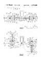
- FIG. 1is a side view of a lead making machine constructed according to one embodiment of the invention, with the terminal attachment presses removed for clarity;
- FIG. 2is an end view of the machine shown in FIG. 1, including the terminal attachment presses;
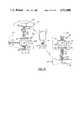
- FIG. 3is an enlarged side view of a portion of the machine shown in FIG. 1, partially in section along line 3--3 of FIG. 2, showing the cutting means and stripping means in the closed position;
- FIG. 4is a fragmentary view of the cutting means and the stripping means of FIG. 3, except shown in the open position;
- FIG. 5is a side view of the machine shown in FIG. 3, showing the gripping means in its retracted position after the wire has been cut and stripped;
- FIG. 6is a top view of the machine according to this invention showing the gripping means in its retracted and non-rotated position
- FIG. 7is an end view of the machine according to this invention showing the gripping means in its rotated position, aligning the wire end with the terminal attachment press preparatory to attachment of a terminal;
- FIG. 8is a view similar to FIG. 7 except that the terminal attachment means is shown clamping down on the terminal to attach it to a stripped wire end;
- FIG. 9is a top view, partially schematic, of the machine according to this invention showing the gripping means in its extended and rotated position;
- FIG. 10is a top view, partially schematic, of the machine according to this invention showing the gripping means in its extended and non-rotated position, with the extended and rotated position shown in phantom;
- FIG. 11is an end view of the gripping means, along line 11--11 of FIG. 5, shown in the closed position, with the open position shown in phantom;
- FIG. 12is a sectional view of the gripping means of FIG. 5, shown in the open position, and taken along line 12--12;
- FIG. 13is a side view of the machine according to the invention, showing the gripping means in its rotated position, aligning the wire end with the terminal attachment press for attachment of a terminal;
- FIG. 14is a top view, partially schematic, of the machine according to this invention showing the gripping means in its retracted and rotated position, with the extended and rotated position shown in phantom;
- FIG. 15is an exploded view of a stripped wire end with a stake-on terminal being applied thereto, while FIG. 16 is an assembled view thereof;
- FIG. 17is an exploded view of a stripped wire end with a barrel-type terminal being applied thereto, while FIG. 18 is an assembled view thereof.
- a machine 30is constructed according to the invention for making electrical leads with a terminal attached to at least one end thereof.
- a frame 40is supplied to provide support to the various components to be described below.
- frame 40includes a central, generally horizontally elongated and vertically arranged pedestal 42 resting lengthwise on a pair of elongated transverse bridges 44, one such bridge 44 supporting each end of the pedestal 42.
- frame 40supports a plurality of arms 46, each of which projects laterally outward from the sides of the frame 40.
- Each of the arms 46in turn supports a platform 48 at a height which is adjustable by means of a slider portion 48a below platform 48 itself, which slider 48a is slidably mounted and received in a tube 46a at the distal end of each arm 46.
- the actual heightmay be fixed by any suitable means such as a set screw 50 which is threaded through the tube 46a and contacts slider 48b to prevent relative movement between the slider 48 a and the tube 46a.
- a terminal attachment means 52rests on and is supported by each platform 48. These terminal attachment means 52 will be described in more detail subsequently.
- the lead making machine 30rests on and is supported by the frame 40.
- the lead making machine 30includes a metering means 54 which receives insulated wire 56 from a wire source (not shown).
- Metering means 54feeds a measured amount of wire 56 to a pair of gripping means 58 and 60 which oppose or face each other.
- Gripping means 58is a wire gripping means while gripping means 60 is a lead gripping means.
- the wire 56is fed by the metering means 54, via flexible tube means 62, to wire gripping means 58, through cutting and stripping means 64, and finally to lead gripping means 60.
- Flexible tube means 62may be any suitable elongated tube having sufficient smoothness and a sufficiently low coefficient of friction on its internal surface to allow wire to pass freely therethrough, and long enough to connect the metering means to the wire gripping means 58.
- the tube 62is a metal spring, which allows almost infinite transverse bending and flexing to accommodate the movement of the wire gripping means 58.
- Gripping means 58 and 60then close on and grip the wire 56 a small distance from each other, facing each other, with the cutting means and stripping means positioned therebetween, as shown in FIG. 4.
- the cutting and stripping means 64close on the wire 56, cutting it off at the location of the cutting means as shown in FIG. 3.
- the length of the lead 68 gripped by the lead gripping means 60is thus established.
- the cutting and stripping means 64cuts through the insulation surrounding the wire 56 a short distance from each side of the point of thw wire cut, without cutting the metal portion of either the wire 56 or lead 68.
- the next stepis that the gripping means 58 and 60 both retract axially from the cutting and stripping means 64, as shown in FIG. 5 and partially schematically in FIG.
- each gripping means 58 and 60rotates about its own generally vertical axis in the same direction as the opposite gripping means is rotating, that is, both may rotate counterclockwise as shown in FIGS. 7 and 8, and partially schematically in FIG. 9, or both may equally well rotate clockwise.
- the gripping means 58 and 60rotate so as to align wire end 56a and lead end 68a with the terminal attachment means 52 so that a terminal may be attached to one or both ends 56a and 68a. If the inspection means 170 determines that the stripped end does not fall within the predetermined parameters, the terminal attachment means 52 is prevented from attaching a terminal. Otherwise the attachment operation proceeds to completion. After terminal attachment means 52 have completed the attachment operation, the gripping means 58 and 60 rotate in the reverse direction so as to restore themselves to their original positions. The gripping means 58 and 60 then release the wire 56 and lead 68 respectively. The lead 68 is collected into a bin 69 (FIG. 1), supported by its own support frame 69a. The wire 56 is then fed into the gripping means 58 and 60 again, and the cycle begins anew.
- a bin 69FIG. 1
- the lead making machine 30includes a metering means 54 which receives insulated wire 56 from a wire source and feeds a measured amount thereof to gripping means 58 and 60.
- metering means 54includes a wire straightening means 70 for taking out all or at least most of the curl which the wire 56 accumulates in the course of storage, such as on a spool or in a barrel.
- Wire straightening means 70includes a plurality of rollers 72 (FIGS. 1 and 3) which are journaled to the frame 40. These rollers 72 force the wire 56 to traverse a path which is straight in at least one plane for a short distance so as to remove any curl in that plane.
- the metering means 54also includes a pair of endless belts 74, each reeved about a first pulley 76 and a second pulley 78 so that belts 74 are arranged coplanarly with each other.
- Each belt 74has a flat continuous outer surface 74a, which outer surfaces face each other for a distance of one flight of each belt 74.
- the second pulley 78is the drive pulley, connected to a prime mover such as an electric motor 80 (FIG.
- the first pulley 76is generally the metering pulley, to which instruments (not shown) are attached to monitor the number of revolutions thereof, and thereby measure the amount of wire 56 passing between the belts 74.
- the motor 80is a servo motor, with the instruments attached thereto for measuring the amount of wire 56 inserted into the machine, in which case the first pulley 76 is merely an idler pulley.
- first pulley 76 and second pulley 78are provided between first pulley 76 and second pulley 78. These rollers are also journaled to the frame 40, and bear on the flight of each belt 74 which faces the opposite belt, so as to ensure proper pressure between the two belts 74 to prevent slippage of the wire 56 with respect to the belts.
- the wire 56is threaded into the nip between the belts 74 and securely held there, without damage to the wire or insulation. Since the belts contact the wire for a distance, that is, the distance between the pulleys 76 and 78, the belts 74 also contribute to the wire straightening function of the wire straightening means 70.
- the beltsmay be toothed belts, with the pulleys and rollers also being toothed so as to mesh with the belts.
- wire 56is fed by the metering means 4, via flexible tube means 62, to wire gripping means 58, through cutting and stripping means 64, and finally to the lead gripping means 60.
- the wire gripping means 58is shown in more detail in FIGS. 3 and 5 through 16, while FIG. 4 shows the cutting and stripping means 64 in more detail.
- the lead gripping means 60is identical to the wire gripping means 58 except that the orientation is rotated 180 degrees about a vertical axis. Hence the wire gripping means 58 will be described in detail, with the description thereof being understood to also describe the lead gripping means 60.
- the wire gripping means 58includes a wire-holding head 90 attached at the distal end of a pair of horizontally oriented slider rods 92.
- Slider rods 92are axially slidably mounted in a sheath portion 94 of a gripping means body 96.
- Body 96is journaled to and supported overhead by a portion 40a of the frame 40. The action of the body 96 will be explained in more detail by reference to the terminal attachment means 52 below.
- Slider rods 92operate the wire-holding head 90 as follows with particular reference to FIGS. 11 and 12.
- FIG. 11is an end view of the wire-holding head 90 from the right end as shown in FIG. 5.
- FIG. 11is an end view of the wire-holding head 90 from the right end as shown in FIG. 5.
- FIG. 12is an end view of the body 96 from the left end as shown in FIG. 5. Also, the same view of the body 96 as shown in FIG. 12, except with the wire-holding head 90 closed, is shown in FIG. 13.
- a power cylinder 122is attached to bracket 102, with its piston 124 arranged to extend vertically downward therefrom.
- a crossbar 126To the end of the piston 124 is attached a crossbar 126.
- An elastomeric bumper means 128may be placed on piston 124 between crossbar 126 and cylinder 122 as a shock absorbing means.
- To each end of crossbar 126is pivotably connected one of two links 130, which in turn each have a lever arm 132 connected rotatably thereto.
- Each such lever arm 132is non-rotatably affixed to one respective slider rod 92.
- a C-shaped clamp means 134is non-rotatably attached to the opposite end of each slider rod 92.
- Slider rods 92are shown in FIG. 3 in their extended position, the position they are in when the wire 56 is fed into the gripping means 58. Slider rods 92 are slid backward (to the left in FIGS. 3 and 10) into a retracted position shown in FIG. 6 by a power cylinder 98, which cylinder 98 is oriented parallel to the slider rods 92. The rod 100 of cylinder 98 is attached to the slider rods 92, at the end opposite the wire-holding head 90, by any suitable means such as bracket 102. Although the cylinder 98 shown in the drawing figures is an air cylinder with a piston 103, the movement of rod 100 may be caused by any suitable means such as a solenoid or hydraulics. As shown in FIGS.
- bracket 104is attached adjustably to the distal end of the rod 100.
- the purpose of bracket 104is to contact a sensor means 106 with one leg 104a thereof so as to discontinue the retraction motion.
- the opposite leg 104bcontacts a shock absorbing means 108 so as to reduce routine impact loading of the assembly.
- the purpose of this retraction of the gripping means 58is to accomplish the stripping of the wire 56 by use of the cutting and stripping means 64 after the wire is cut.
- the cutting and stripping means 64include a pair of generally vertically oriented power cylinders 110 and 111, with cylinder 110 located above the wire 56 and cylinder 111 below.
- the cutting and stripping means 64also includes a pair of cutting knives 65, facing each other and arranged to pass by each other closely so as to shear anything between them in guillotine fashion.
- the upper cutting knife 65is attached to the upper power cylinder 110, while the lower cutting knife 65 is affixed to the power cylinder 111.
- Both cylinders 110 and 111are attached to and supported by a standard 116 which in turn is attached to and supported by the frame 40.
- the preferred embodiment of the cutting and stripping means 64includes a one pair of stripping knives 66 located on each side of cutting knives 65, and arranged parallel to and spaced apart from the cutting knives 65. While cutting knives 65 are attached to cylinders 110 and 111 so as to pass by each other and cut off the wire set between them, stripping knives 66 are on the other hand attached to cylinders 110 and 111 respectively so as to partially but not completely pass by each other, thereby cutting through the insulation surrounding the wire and holding the insulation without cutting or in any way damaging the wire 56.
- the cylinders 110 and 111force cutting knives 65 and stripping knives 66 together, thereby cutting through the wire 56 at one point and cutting through the insulation at a point on each side of the wire cut, without causing any interference with the passage of the wire 56 during loading or measuring.
- the gripping means 58 and 60then move from their extended position to their retracted position, pulling the wire 56 and lead 68 out of the insulation held by the cutting and stripping means 64, to the position shown in FIG. 5 and in top view in FIG. 6. The remaining insulation may then be removed by any suitable means.
- wire gripping means 58is rotatable about a generally vertical axis 136, the location of which coincides with a generally vertically oriented shaft 138.
- Shaft 138is joined to body 96 at the lower end of the shaft 138 and projects upward through frame portion 40a, journaled thereto and ending slightly thereabove.
- the axis of rotationpasses approximately through the center of gravity of the wire gripping means 58. The purpose of this centering of the axis of rotation is to reduce the swinging mass of the wire gripping means 58 during rotation, so as to allow an increase in speed and throughput over previously known machines.
- the rotation of the wire gripping means 58is accomplished as follows referring to FIG. 3.
- the upper frame portion 40asupports and has attached thereto a power cylinder 140 with a rod 142 extending to the right in that figure.
- the opposite end of that rod 142is rotatably connected to a pivot arm 144 which in turn is non-rotatably affixed to the shaft 138 so that, when the rod 142 is extended, the body 96 is positioned so as to align the wire-holding head 90 with the cutting means 66 and stripping means 64.
- the rod 142is drawn into the cylinder 140, the body is rotated so as to align the wire-holding head 90 with the terminal attachment means 52, as shown in FIG. 7 and in top view in FIG. 9. Notice also in FIG. 9 that the gripping means has returned to its extended position during the course of the rotation.
- Each terminal attachment means 52includes a generally conventional terminal attachment press 146 (FIG. 2) which is fed terminals attached together in a chain-like manner 148 from a reel or other source 150.
- the operation of terminal attachment means 52 and the cooperation thereof with the gripping means 58 in one mode of operationcan be seen by comparing FIG. 7 to FIG. 8.
- wire gripping means 58has already been simultaneously rotated and extended so as to align the wire end 56a over a typical stake-on type terminal 152.
- FIG. 15shows the relative orientation of the wire end 56a to the stake-on terminal 152.
- a tab 154is attached to the press 146, and protrudes laterally outward therefrom.
- a spring 156Suspended vertically downward from the tab 154 is a spring 156.
- Tab 154 and spring 156are located so as to be just above wire-holding head 90 when wire gripping means 58 has rotated to align stripped wire end 56a with the terminal attachment means 52. Then, when press 146 is lowered, spring 156 presses down on wire-holding head 90, causing gripping means body 96 to rotate slightly about a horizontally pivotable mounting axis 158, enough that the wire end 56a is lowered onto the terminal 152 before the die portion 160 of press 146 contacts the terminal. Biasing means 161 and stop means 163 (FIG.
- the wire gripping means 58is extended during the course of the rotation when a stake-on type terminal 152 is to be attached to the stripped wire end 56a. If on the other hand a barrel type terminal 164 (FIG. 17) is to be attached to the stripped wire end 56a, the wire gripping means 58 is not extended while it is being rotated. Rather, as shown in top view in FIG. 14, it is held in the retracted position until it is fully rotated. After the rotation is complete, the wire gripping means 58 is extended, sliding the stripped wire end 56a into the terminal 164 as shown in FIG. 17. As mentioned earlier, the height of the terminal attachment means 52 may be adjusted by use of tubes 46a, sliders 48a and set screws 50.
- the pressis then lowered and the terminal clamped to the wire end to produce the terminated wire end 166 shown in FIG. 18.
- the decision as to whether to extend the wire gripping means 58 concurrently with its rotation or to extend only after completion of the rotationis made by a human operator (not shown) and the order is given by use of a control means 168 (FIG. 1) supported by the frame 40 and electrically or otherwise connected to the various parts of the machine 30. Further, the wire gripping means 58 and the lead gripping means 60 may be controlled independently. There is thus no reason why a barrel-type terminal 164 could not be attached to one end of a lead and a stake-on type terminal 152 attached to the opposite end.
- FIG. 5Another advantageous feature of this invention is that it will readily receive an inspecting means 170 (FIG. 5) for inspecting the stripped wire end 56a and stripped lead end 68a for ensuring that the stripped ends meet certain predetermined parameters, and for preventing the terminal attachment means from attaching a terminal to the particular wire end if the end is outside those parameters.
- inspecting means 170FIG. 5
- the inspection means 170includes two illuminated fields 172, one located beneath the stripped wire end 56a and one located beneath the stripped lead end 68a, when both gripping means 58 and 60 are in their retracted and non-rotated positions.
- Each illuminated field 172includes a light source 174, and a translucent surface 176 located between the light source 174 and the respective wire end 56a or 68a.
- the gripping means 58 and 60pause for a short period (preferably on the order of 50 milliseconds) in this retracted and non-rotated position.
- An optical lens 178is located opposite the illuminated field 172 so that the respective stripped end 56a or 68a is located between the lens and the field during the pause.
- a control means(not shown) is located inside a control enclose 18, which enclosure is supported. by frame portion 40a.
- This control meansaccepts an optical image from the lens 178 during the pause, subsequently determines whether the parameters of the respective end fall within the predetermined parameters for a properly stripped end, and controls the terminal attachment means accordingly. If the end is proper, a terminal is attached thereto as if the inspection means 170 did not exist. If the end is not properly stripped, the terminal attachment means is disabled from attaching a terminal thereto.
- leads having improperly stripped endsmay be easily discovered and removed from the collection bin 69 before they are used in an electrical circuit where they could malfunction. This is true because improperly stripped leads are much more readily distinguished by not having terminals attached, rather than attaching the terminals to defectively stripped leads and later testing them to ensure quality. This has the effect of reducing overall waste.
Landscapes
- Engineering & Computer Science (AREA)
- Manufacturing & Machinery (AREA)
- Manufacturing Of Electrical Connectors (AREA)
Abstract
Description
Claims (11)
Priority Applications (1)
| Application Number | Priority Date | Filing Date | Title |
|---|---|---|---|
| US07/024,887US4713880A (en) | 1986-04-08 | 1987-03-11 | Lead making machine |
Applications Claiming Priority (2)
| Application Number | Priority Date | Filing Date | Title |
|---|---|---|---|
| US84956486A | 1986-04-08 | 1986-04-08 | |
| US07/024,887US4713880A (en) | 1986-04-08 | 1987-03-11 | Lead making machine |
Related Parent Applications (1)
| Application Number | Title | Priority Date | Filing Date |
|---|---|---|---|
| US84956486AContinuation | 1986-04-08 | 1986-04-08 |
Publications (1)
| Publication Number | Publication Date |
|---|---|
| US4713880Atrue US4713880A (en) | 1987-12-22 |
Family
ID=26698990
Family Applications (1)
| Application Number | Title | Priority Date | Filing Date |
|---|---|---|---|
| US07/024,887Expired - Fee RelatedUS4713880A (en) | 1986-04-08 | 1987-03-11 | Lead making machine |
Country Status (1)
| Country | Link |
|---|---|
| US (1) | US4713880A (en) |
Cited By (39)
| Publication number | Priority date | Publication date | Assignee | Title |
|---|---|---|---|---|
| DE3909093A1 (en)* | 1988-03-31 | 1989-10-12 | Artos Engineering Co | METHOD AND DEVICE FOR PROCESSING CABLE MATERIAL |
| US4873901A (en)* | 1988-09-16 | 1989-10-17 | Artos Engineering Company | Apparatus for cutting and stripping insulation from wire segments having different gauge conductors |
| JPH02214405A (en)* | 1988-12-22 | 1990-08-27 | Molex Inc | Method and device for peeling and termination treatment of multicore electric cable conductor |
| US5025549A (en)* | 1990-08-31 | 1991-06-25 | Amp Incorporated | Lead making machine having improved wire feeding system |
| US5027487A (en)* | 1990-06-26 | 1991-07-02 | Eubanks Engineering Company | Geneva mechanism control for wire displacement |
| US5038457A (en)* | 1988-04-27 | 1991-08-13 | Shin Meiwa Industry Co., Ltd. | Harness producing apparatus |
| US5109590A (en)* | 1989-12-21 | 1992-05-05 | Molex Incorporated | Multi core cable stripping |
| DE4127843A1 (en)* | 1991-08-22 | 1993-02-25 | Wallrabenstein Guenther Ing Gr | Automatic electrical cable preparation machine - feeds cable through guides to manipulator controlled to remove insulation and for connector before cutting to length |
| US5247732A (en)* | 1991-04-09 | 1993-09-28 | British Aerospace Public Limited Company | Cable handling and preparation apparatus |
| US5398573A (en)* | 1992-06-24 | 1995-03-21 | Artos Engineering Company | Adjustable wire cutting and stripping apparatus |
| US5402693A (en)* | 1990-11-09 | 1995-04-04 | Eubanks Engineering Company | Multiple blade set strip apparatus for cable and wire |
| US5412856A (en)* | 1991-09-26 | 1995-05-09 | Eubanks Engineering Company | Wire marking, cutting and stripping apparatus and method |
| WO1995013641A1 (en)* | 1993-11-08 | 1995-05-18 | Eubanks Engineering Company | Wire and cable processing system |
| US5456148A (en)* | 1990-11-09 | 1995-10-10 | Eubanks Engineering Company | Wire and cable drive apparatus in wire and cable cutting and stripping system |
| US5490316A (en)* | 1993-06-11 | 1996-02-13 | Sumitomo Wiring Systems Ltd (A Corp. Of Japan) | Continuous terminal crimping machine |
| EP0707365A1 (en)* | 1990-11-09 | 1996-04-17 | Eubanks Engineering Company | Multiple blade set strip apparatus for cable and wire |
| US5515602A (en)* | 1990-11-09 | 1996-05-14 | Eubanks Engineering Company | Multiple blade set strip apparatus for cable and wire |
| US5517882A (en)* | 1990-11-09 | 1996-05-21 | Eubanks Engineering Company | Wire and cable cutting and stripping using slidable interfitting blades with complementary configurations |
| US5528962A (en)* | 1990-11-09 | 1996-06-25 | Eubanks Engineering Company | Multiple blade set strip apparatus for cable and wire |
| US5582078A (en)* | 1992-05-18 | 1996-12-10 | Eubanks Engineering Company | Wire displacing and stripping apparatus and method |
| US5630341A (en)* | 1990-11-09 | 1997-05-20 | Eubanks Engineering Co. | Method for processing cable and wire |
| US5664324A (en)* | 1990-11-09 | 1997-09-09 | Eubanks Engineering Company | Wire and cable cutting and stripping using adjacent blades |
| US5689874A (en)* | 1996-09-20 | 1997-11-25 | The Whitaker Corporation | Wire cut and strip mechanism |
| EP0815982A3 (en)* | 1996-02-14 | 1998-01-28 | Metzner Maschinenbau GmbH | Wire guiding device for the treatment of wire ends |
| US5979272A (en)* | 1997-02-10 | 1999-11-09 | Artos Engineering Company | Device for gathering, cutting and stripping insulated wire |
| US6212757B1 (en)* | 1998-10-19 | 2001-04-10 | Yazaki Corporation | Automatic cutting and crimping apparatus |
| US6230386B1 (en)* | 1998-10-13 | 2001-05-15 | Yazaki Corporation | Automatic cutting and press-fitting apparatus for electric wire |
| US6266870B1 (en) | 1999-09-15 | 2001-07-31 | Autos Engineering Co. | Wire positioning mechanism for a terminal attaching apparatus |
| US6286393B1 (en)* | 1997-04-14 | 2001-09-11 | Schleuniger Holding Ag | Insulation device |
| US6289573B1 (en)* | 1998-09-21 | 2001-09-18 | Komax Holding Ag | Apparatus for making up a cable |
| WO2002089267A1 (en)* | 2001-05-02 | 2002-11-07 | Schleuniger Holding Ag | Device for treating and/or processing the ends of wires |
| US20030172529A1 (en)* | 2002-03-18 | 2003-09-18 | Alois Conte | Crimp press for the production of a crimping connection |
| EP1351349A1 (en)* | 2002-03-18 | 2003-10-08 | Komax Holding Ag | Crimping press for making crimp connections |
| US20030226426A1 (en)* | 2002-06-06 | 2003-12-11 | Komax Holding Ag | Method and device for processing cables |
| US20060230597A1 (en)* | 2005-04-14 | 2006-10-19 | Delphi Technologies, Inc. | Multiple wire feed machine and process for terminating electric cable |
| EP2590275A1 (en) | 2011-11-02 | 2013-05-08 | Schleuniger Holding AG | Circuit positioning device |
| US20150128399A1 (en)* | 2013-11-11 | 2015-05-14 | Schleuniger Holding Ag | Facility for the processing of a multi-core cable |
| US20170310092A1 (en)* | 2016-04-21 | 2017-10-26 | Komax Holding Ag | Method and device for stripping a cable |
| EP4084246A1 (en)* | 2021-04-26 | 2022-11-02 | Schäfer Werkzeug- und Sondermaschinenbau GmbH | Cable processing device |
Citations (9)
| Publication number | Priority date | Publication date | Assignee | Title |
|---|---|---|---|---|
| US2756619A (en)* | 1952-07-18 | 1956-07-31 | Herbert D Scharf | Wire cutting and stripping machines |
| US2954599A (en)* | 1956-09-18 | 1960-10-04 | Amp Inc | Lead making apparatus |
| US3019679A (en)* | 1958-07-15 | 1962-02-06 | Amp Inc | Lead making machine |
| US3155136A (en)* | 1960-12-29 | 1964-11-03 | Gen Electric | Apparatus for fabricating wireconnector assemblies |
| US3368428A (en)* | 1966-09-12 | 1968-02-13 | Artos Engineering Co | Wire cutting and stripping machine |
| US3612369A (en)* | 1969-11-14 | 1971-10-12 | Amp Inc | Wire feed for lead making machine |
| US4087908A (en)* | 1976-02-18 | 1978-05-09 | Molex Incorporated | Connector harness assembly machine |
| US4249433A (en)* | 1978-09-07 | 1981-02-10 | Osawa Press Mfg. Co., Ltd. | Sheathed wire end portion processing machine |
| US4454652A (en)* | 1978-09-29 | 1984-06-19 | Yazaki Corporation | Method of processing end portions of covered wires |
- 1987
- 1987-03-11USUS07/024,887patent/US4713880A/ennot_activeExpired - Fee Related
Patent Citations (9)
| Publication number | Priority date | Publication date | Assignee | Title |
|---|---|---|---|---|
| US2756619A (en)* | 1952-07-18 | 1956-07-31 | Herbert D Scharf | Wire cutting and stripping machines |
| US2954599A (en)* | 1956-09-18 | 1960-10-04 | Amp Inc | Lead making apparatus |
| US3019679A (en)* | 1958-07-15 | 1962-02-06 | Amp Inc | Lead making machine |
| US3155136A (en)* | 1960-12-29 | 1964-11-03 | Gen Electric | Apparatus for fabricating wireconnector assemblies |
| US3368428A (en)* | 1966-09-12 | 1968-02-13 | Artos Engineering Co | Wire cutting and stripping machine |
| US3612369A (en)* | 1969-11-14 | 1971-10-12 | Amp Inc | Wire feed for lead making machine |
| US4087908A (en)* | 1976-02-18 | 1978-05-09 | Molex Incorporated | Connector harness assembly machine |
| US4249433A (en)* | 1978-09-07 | 1981-02-10 | Osawa Press Mfg. Co., Ltd. | Sheathed wire end portion processing machine |
| US4454652A (en)* | 1978-09-29 | 1984-06-19 | Yazaki Corporation | Method of processing end portions of covered wires |
Non-Patent Citations (1)
| Title |
|---|
| Komax Model 40 Brochure, undated, Komax Corporation, Northbrook, Ill.* |
Cited By (62)
| Publication number | Priority date | Publication date | Assignee | Title |
|---|---|---|---|---|
| DE3909093A1 (en)* | 1988-03-31 | 1989-10-12 | Artos Engineering Co | METHOD AND DEVICE FOR PROCESSING CABLE MATERIAL |
| JPH0610937B2 (en) | 1988-03-31 | 1994-02-09 | アートス エンジニヤリング カンパニー | Wire processing method and apparatus |
| EP0365691A4 (en)* | 1988-04-27 | 1993-09-15 | Shin Meiwa Industry Co., Ltd. | Harness manufacturing apparatus |
| US5038457A (en)* | 1988-04-27 | 1991-08-13 | Shin Meiwa Industry Co., Ltd. | Harness producing apparatus |
| US4873901A (en)* | 1988-09-16 | 1989-10-17 | Artos Engineering Company | Apparatus for cutting and stripping insulation from wire segments having different gauge conductors |
| DE3928196A1 (en)* | 1988-09-16 | 1990-03-22 | Artos Engineering Co | DEVICE FOR CUTTING THE INSULATION AND STRIPING THE SAME OF LADDER CORES OF DIFFERENT DIAMETERS CONTAINING DIAMETERS |
| JPH02214405A (en)* | 1988-12-22 | 1990-08-27 | Molex Inc | Method and device for peeling and termination treatment of multicore electric cable conductor |
| JPH0785616B2 (en) | 1988-12-22 | 1995-09-13 | モレックス インコーポレーテッド | Equipment for stripping and terminating multiconductor electrical cable conductors |
| US5109590A (en)* | 1989-12-21 | 1992-05-05 | Molex Incorporated | Multi core cable stripping |
| US5027487A (en)* | 1990-06-26 | 1991-07-02 | Eubanks Engineering Company | Geneva mechanism control for wire displacement |
| US5025549A (en)* | 1990-08-31 | 1991-06-25 | Amp Incorporated | Lead making machine having improved wire feeding system |
| US6336267B1 (en) | 1990-11-09 | 2002-01-08 | Eubanks Engineering Co. | Wire and cable cutting and stripping apparatus using endless belt conveyors |
| US5528962A (en)* | 1990-11-09 | 1996-06-25 | Eubanks Engineering Company | Multiple blade set strip apparatus for cable and wire |
| US5402693A (en)* | 1990-11-09 | 1995-04-04 | Eubanks Engineering Company | Multiple blade set strip apparatus for cable and wire |
| US5937511A (en)* | 1990-11-09 | 1999-08-17 | Eubanks Engineering Co. | Wire and cable cutting and stripping using adjacent blades |
| US20020059720A1 (en)* | 1990-11-09 | 2002-05-23 | Hoffa Jack L. | Wire and cable cutting and stripping using adjacent blades |
| US5664324A (en)* | 1990-11-09 | 1997-09-09 | Eubanks Engineering Company | Wire and cable cutting and stripping using adjacent blades |
| US5456148A (en)* | 1990-11-09 | 1995-10-10 | Eubanks Engineering Company | Wire and cable drive apparatus in wire and cable cutting and stripping system |
| US5469763A (en)* | 1990-11-09 | 1995-11-28 | Eubanks Engineering Company | Wire and cable processing system |
| US5653016A (en)* | 1990-11-09 | 1997-08-05 | Eubanks Engineering Company | Wire and cable drive apparatus in wire and cable cutting and stripping system |
| EP0707365A1 (en)* | 1990-11-09 | 1996-04-17 | Eubanks Engineering Company | Multiple blade set strip apparatus for cable and wire |
| US5515602A (en)* | 1990-11-09 | 1996-05-14 | Eubanks Engineering Company | Multiple blade set strip apparatus for cable and wire |
| US5517882A (en)* | 1990-11-09 | 1996-05-21 | Eubanks Engineering Company | Wire and cable cutting and stripping using slidable interfitting blades with complementary configurations |
| US5526718A (en)* | 1990-11-09 | 1996-06-18 | Eubanks Engineering Company | Multiple blade set strip apparatus for cable and wire |
| US6854177B2 (en) | 1990-11-09 | 2005-02-15 | Eubanks Engineering Co. | Apparatus for processing wire |
| US5539967A (en)* | 1990-11-09 | 1996-07-30 | Eubanks Engineering Company | Multiple blade set strip apparatus for cable and wire |
| US6272740B1 (en) | 1990-11-09 | 2001-08-14 | Eubanks Engineering Co. | Wire and cable cutting and stripping using endless belt conveyors |
| US5630341A (en)* | 1990-11-09 | 1997-05-20 | Eubanks Engineering Co. | Method for processing cable and wire |
| US5640891A (en)* | 1990-11-09 | 1997-06-24 | Eubanks Engineering Co. | Wire and cable drive apparatus in wire and cable cutting and stripping system |
| US5247732A (en)* | 1991-04-09 | 1993-09-28 | British Aerospace Public Limited Company | Cable handling and preparation apparatus |
| DE4127843A1 (en)* | 1991-08-22 | 1993-02-25 | Wallrabenstein Guenther Ing Gr | Automatic electrical cable preparation machine - feeds cable through guides to manipulator controlled to remove insulation and for connector before cutting to length |
| US5412856A (en)* | 1991-09-26 | 1995-05-09 | Eubanks Engineering Company | Wire marking, cutting and stripping apparatus and method |
| US5787768A (en)* | 1992-05-18 | 1998-08-04 | Eubanks Engineering Co. | Wire displacing and stripping apparatus and method |
| US5582078A (en)* | 1992-05-18 | 1996-12-10 | Eubanks Engineering Company | Wire displacing and stripping apparatus and method |
| US5398573A (en)* | 1992-06-24 | 1995-03-21 | Artos Engineering Company | Adjustable wire cutting and stripping apparatus |
| US5490316A (en)* | 1993-06-11 | 1996-02-13 | Sumitomo Wiring Systems Ltd (A Corp. Of Japan) | Continuous terminal crimping machine |
| WO1995013641A1 (en)* | 1993-11-08 | 1995-05-18 | Eubanks Engineering Company | Wire and cable processing system |
| EP0815982A3 (en)* | 1996-02-14 | 1998-01-28 | Metzner Maschinenbau GmbH | Wire guiding device for the treatment of wire ends |
| US5689874A (en)* | 1996-09-20 | 1997-11-25 | The Whitaker Corporation | Wire cut and strip mechanism |
| US5979272A (en)* | 1997-02-10 | 1999-11-09 | Artos Engineering Company | Device for gathering, cutting and stripping insulated wire |
| US6286393B1 (en)* | 1997-04-14 | 2001-09-11 | Schleuniger Holding Ag | Insulation device |
| US6289573B1 (en)* | 1998-09-21 | 2001-09-18 | Komax Holding Ag | Apparatus for making up a cable |
| US6230386B1 (en)* | 1998-10-13 | 2001-05-15 | Yazaki Corporation | Automatic cutting and press-fitting apparatus for electric wire |
| US6212757B1 (en)* | 1998-10-19 | 2001-04-10 | Yazaki Corporation | Automatic cutting and crimping apparatus |
| US6266870B1 (en) | 1999-09-15 | 2001-07-31 | Autos Engineering Co. | Wire positioning mechanism for a terminal attaching apparatus |
| WO2002089267A1 (en)* | 2001-05-02 | 2002-11-07 | Schleuniger Holding Ag | Device for treating and/or processing the ends of wires |
| EP1351349A1 (en)* | 2002-03-18 | 2003-10-08 | Komax Holding Ag | Crimping press for making crimp connections |
| US20030172529A1 (en)* | 2002-03-18 | 2003-09-18 | Alois Conte | Crimp press for the production of a crimping connection |
| US7562441B2 (en) | 2002-03-18 | 2009-07-21 | Komax Holdings AG | Crimp press for the production of a crimping connection |
| US20030226426A1 (en)* | 2002-06-06 | 2003-12-11 | Komax Holding Ag | Method and device for processing cables |
| US7028384B2 (en)* | 2002-06-06 | 2006-04-18 | Komax Holding Ag | Method and device for processing cables |
| US20060230597A1 (en)* | 2005-04-14 | 2006-10-19 | Delphi Technologies, Inc. | Multiple wire feed machine and process for terminating electric cable |
| US7251876B2 (en)* | 2005-04-14 | 2007-08-07 | Delphi Technologies, Inc. | Multiple wire feed machine and process for terminating electric cable |
| EP2590275A1 (en) | 2011-11-02 | 2013-05-08 | Schleuniger Holding AG | Circuit positioning device |
| EP2590275B1 (en)* | 2011-11-02 | 2016-03-02 | Schleuniger Holding AG | Circuit positioning device |
| US20150128399A1 (en)* | 2013-11-11 | 2015-05-14 | Schleuniger Holding Ag | Facility for the processing of a multi-core cable |
| CN104638497A (en)* | 2013-11-11 | 2015-05-20 | 施洛伊尼格控股有限公司 | Facility for the processing of a multi-core cable |
| US9954346B2 (en)* | 2013-11-11 | 2018-04-24 | Schleuniger Holding Ag | Facility for the processing of a multi-core cable |
| CN104638497B (en)* | 2013-11-11 | 2019-08-20 | 施洛伊尼格控股有限公司 | Equipment for processing multi-core cables |
| US20170310092A1 (en)* | 2016-04-21 | 2017-10-26 | Komax Holding Ag | Method and device for stripping a cable |
| US10666028B2 (en)* | 2017-04-21 | 2020-05-26 | Komax Holding Ag | Method for stripping a cable |
| EP4084246A1 (en)* | 2021-04-26 | 2022-11-02 | Schäfer Werkzeug- und Sondermaschinenbau GmbH | Cable processing device |
Similar Documents
| Publication | Publication Date | Title |
|---|---|---|
| US4713880A (en) | Lead making machine | |
| CN109888591B (en) | Automatic harness assembling machine with double-end-beating and shell-inserting functions | |
| US4916811A (en) | Process and apparatus for automatically attaching terminals to cable ends | |
| US4493233A (en) | Apparatus for cutting and conveying segments of wire or cable | |
| US4164808A (en) | Apparatus for producing sets of accurately and identically sized wire leads | |
| CA1102661A (en) | Electric cable processing | |
| JP3633983B2 (en) | Needle-suture attachment station | |
| US4377898A (en) | Wire end processing apparatus | |
| JPS6034211A (en) | Electric wire sizing cutting device | |
| CN219303390U (en) | New energy automobile charging cable automatic processing equipment | |
| US4099428A (en) | Cutting and insulation stripping apparatus for twisted wire pair | |
| JPS6171575A (en) | One side end automatic pressure welding machine | |
| CN209896427U (en) | Line processing mechanism of DC terminal electric lead | |
| CN113933543B (en) | Communication pencil line order intellectual detection system equipment | |
| CN110718388A (en) | Winding device for producing NR inductor | |
| US4614135A (en) | Stripping device for stripping coated wire | |
| US5406692A (en) | Wire reversing apparatus in wire terminating equipment | |
| SU1134266A1 (en) | Device for cutting wire to length | |
| US4249433A (en) | Sheathed wire end portion processing machine | |
| US5842266A (en) | Apparatus for producing wire harnesses | |
| US6353993B1 (en) | Cable finishing and resistance testing machine | |
| EP0801826B1 (en) | Apparatus for producing wire harnesses | |
| CN219419795U (en) | Full-automatic processing equipment for two-core round sheath wire | |
| CN117614220A (en) | Efficient stator winding machine | |
| CN109904702B (en) | Full-automatic copper belt machine and operation method thereof |
Legal Events
| Date | Code | Title | Description |
|---|---|---|---|
| AS | Assignment | Owner name:FIRST BANK (N.A.), WISCONSIN Free format text:SECURITY INTEREST;ASSIGNOR:ARTOS ENGINEERING COMPANY;REEL/FRAME:005362/0428 Effective date:19900629 Owner name:FIRST WISCONSIN NATIONAL BANK OF MILWAUKEE, A NATI Free format text:SECURITY INTEREST;ASSIGNOR:ARTOS ENGINEERING COMPANY;REEL/FRAME:005362/0401 Effective date:19900629 Owner name:M & I MARSHALL & ILSLEY BANK, A NATIONAL BANKING A Free format text:SECURITY INTEREST;ASSIGNOR:ARTOS ENGINEERING COMPANY;REEL/FRAME:005362/0455 Effective date:19900629 | |
| FEPP | Fee payment procedure | Free format text:PAYOR NUMBER ASSIGNED (ORIGINAL EVENT CODE: ASPN); ENTITY STATUS OF PATENT OWNER: LARGE ENTITY | |
| FPAY | Fee payment | Year of fee payment:4 | |
| FEPP | Fee payment procedure | Free format text:PAYER NUMBER DE-ASSIGNED (ORIGINAL EVENT CODE: RMPN); ENTITY STATUS OF PATENT OWNER: LARGE ENTITY Free format text:PAYOR NUMBER ASSIGNED (ORIGINAL EVENT CODE: ASPN); ENTITY STATUS OF PATENT OWNER: LARGE ENTITY | |
| REMI | Maintenance fee reminder mailed | ||
| LAPS | Lapse for failure to pay maintenance fees | ||
| FP | Lapsed due to failure to pay maintenance fee | Effective date:19951227 | |
| STCH | Information on status: patent discontinuation | Free format text:PATENT EXPIRED DUE TO NONPAYMENT OF MAINTENANCE FEES UNDER 37 CFR 1.362 |