US4712969A - Expandable and contractable arms - Google Patents
Expandable and contractable armsDownload PDFInfo
- Publication number
- US4712969A US4712969AUS06/643,793US64379384AUS4712969AUS 4712969 AUS4712969 AUS 4712969AUS 64379384 AUS64379384 AUS 64379384AUS 4712969 AUS4712969 AUS 4712969A
- Authority
- US
- United States
- Prior art keywords
- links
- arm
- arm according
- secured
- unit
- Prior art date
- Legal status (The legal status is an assumption and is not a legal conclusion. Google has not performed a legal analysis and makes no representation as to the accuracy of the status listed.)
- Expired - Fee Related
Links
- 230000007246mechanismEffects0.000claimsabstractdescription20
- 239000002131composite materialSubstances0.000claimsdescription5
- 230000006835compressionEffects0.000claimsdescription3
- 238000007906compressionMethods0.000claimsdescription3
- 239000012530fluidSubstances0.000claimsdescription2
- 238000010438heat treatmentMethods0.000claimsdescription2
- 229910001285shape-memory alloyInorganic materials0.000claimsdescription2
- 238000005452bendingMethods0.000claims1
- 230000004048modificationEffects0.000description8
- 238000012986modificationMethods0.000description8
- 230000000712assemblyEffects0.000description5
- 238000000429assemblyMethods0.000description5
- 230000002441reversible effectEffects0.000description4
- 230000008878couplingEffects0.000description2
- 238000010168coupling processMethods0.000description2
- 238000005859coupling reactionMethods0.000description2
- 238000010276constructionMethods0.000description1
- 230000008602contractionEffects0.000description1
- 230000003247decreasing effectEffects0.000description1
- 230000000694effectsEffects0.000description1
- 238000000034methodMethods0.000description1
- 239000000941radioactive substanceSubstances0.000description1
Images


Classifications
- B—PERFORMING OPERATIONS; TRANSPORTING
- B25—HAND TOOLS; PORTABLE POWER-DRIVEN TOOLS; MANIPULATORS
- B25J—MANIPULATORS; CHAMBERS PROVIDED WITH MANIPULATION DEVICES
- B25J17/00—Joints
- B25J17/02—Wrist joints
- B25J17/0258—Two-dimensional joints
- B25J17/0266—Two-dimensional joints comprising more than two actuating or connecting rods
- B—PERFORMING OPERATIONS; TRANSPORTING
- B25—HAND TOOLS; PORTABLE POWER-DRIVEN TOOLS; MANIPULATORS
- B25J—MANIPULATORS; CHAMBERS PROVIDED WITH MANIPULATION DEVICES
- B25J18/00—Arms
- B25J18/06—Arms flexible
- B—PERFORMING OPERATIONS; TRANSPORTING
- B25—HAND TOOLS; PORTABLE POWER-DRIVEN TOOLS; MANIPULATORS
- B25J—MANIPULATORS; CHAMBERS PROVIDED WITH MANIPULATION DEVICES
- B25J9/00—Programme-controlled manipulators
- B25J9/003—Programme-controlled manipulators having parallel kinematics
- B25J9/0075—Truss
- B—PERFORMING OPERATIONS; TRANSPORTING
- B25—HAND TOOLS; PORTABLE POWER-DRIVEN TOOLS; MANIPULATORS
- B25J—MANIPULATORS; CHAMBERS PROVIDED WITH MANIPULATION DEVICES
- B25J9/00—Programme-controlled manipulators
- B25J9/06—Programme-controlled manipulators characterised by multi-articulated arms
- B—PERFORMING OPERATIONS; TRANSPORTING
- B25—HAND TOOLS; PORTABLE POWER-DRIVEN TOOLS; MANIPULATORS
- B25J—MANIPULATORS; CHAMBERS PROVIDED WITH MANIPULATION DEVICES
- B25J9/00—Programme-controlled manipulators
- B25J9/10—Programme-controlled manipulators characterised by positioning means for manipulator elements
- B25J9/1085—Programme-controlled manipulators characterised by positioning means for manipulator elements positioning by means of shape-memory materials
- Y—GENERAL TAGGING OF NEW TECHNOLOGICAL DEVELOPMENTS; GENERAL TAGGING OF CROSS-SECTIONAL TECHNOLOGIES SPANNING OVER SEVERAL SECTIONS OF THE IPC; TECHNICAL SUBJECTS COVERED BY FORMER USPC CROSS-REFERENCE ART COLLECTIONS [XRACs] AND DIGESTS
- Y10—TECHNICAL SUBJECTS COVERED BY FORMER USPC
- Y10T—TECHNICAL SUBJECTS COVERED BY FORMER US CLASSIFICATION
- Y10T403/00—Joints and connections
- Y10T403/32—Articulated members
- Y10T403/32008—Plural distinct articulation axes
- Y10T403/32057—Angular and linear
- Y10T403/32065—Screw and swivel
- Y—GENERAL TAGGING OF NEW TECHNOLOGICAL DEVELOPMENTS; GENERAL TAGGING OF CROSS-SECTIONAL TECHNOLOGIES SPANNING OVER SEVERAL SECTIONS OF THE IPC; TECHNICAL SUBJECTS COVERED BY FORMER USPC CROSS-REFERENCE ART COLLECTIONS [XRACs] AND DIGESTS
- Y10—TECHNICAL SUBJECTS COVERED BY FORMER USPC
- Y10T—TECHNICAL SUBJECTS COVERED BY FORMER US CLASSIFICATION
- Y10T403/00—Joints and connections
- Y10T403/32—Articulated members
- Y10T403/32114—Articulated members including static joint
- Y10T403/32196—Articulate joint is ball and socket
- Y10T403/32204—Articulate joint is ball and socket with threaded joint
- Y—GENERAL TAGGING OF NEW TECHNOLOGICAL DEVELOPMENTS; GENERAL TAGGING OF CROSS-SECTIONAL TECHNOLOGIES SPANNING OVER SEVERAL SECTIONS OF THE IPC; TECHNICAL SUBJECTS COVERED BY FORMER USPC CROSS-REFERENCE ART COLLECTIONS [XRACs] AND DIGESTS
- Y10—TECHNICAL SUBJECTS COVERED BY FORMER USPC
- Y10T—TECHNICAL SUBJECTS COVERED BY FORMER US CLASSIFICATION
- Y10T74/00—Machine element or mechanism
- Y10T74/18—Mechanical movements
- Y10T74/18568—Reciprocating or oscillating to or from alternating rotary
- Y10T74/18576—Reciprocating or oscillating to or from alternating rotary including screw and nut
- Y10T74/18624—Plural inputs, single output
- Y—GENERAL TAGGING OF NEW TECHNOLOGICAL DEVELOPMENTS; GENERAL TAGGING OF CROSS-SECTIONAL TECHNOLOGIES SPANNING OVER SEVERAL SECTIONS OF THE IPC; TECHNICAL SUBJECTS COVERED BY FORMER USPC CROSS-REFERENCE ART COLLECTIONS [XRACs] AND DIGESTS
- Y10—TECHNICAL SUBJECTS COVERED BY FORMER USPC
- Y10T—TECHNICAL SUBJECTS COVERED BY FORMER US CLASSIFICATION
- Y10T74/00—Machine element or mechanism
- Y10T74/18—Mechanical movements
- Y10T74/18568—Reciprocating or oscillating to or from alternating rotary
- Y10T74/18576—Reciprocating or oscillating to or from alternating rotary including screw and nut
- Y10T74/18672—Plural screws in series [e.g., telescoping, etc.]
- Y—GENERAL TAGGING OF NEW TECHNOLOGICAL DEVELOPMENTS; GENERAL TAGGING OF CROSS-SECTIONAL TECHNOLOGIES SPANNING OVER SEVERAL SECTIONS OF THE IPC; TECHNICAL SUBJECTS COVERED BY FORMER USPC CROSS-REFERENCE ART COLLECTIONS [XRACs] AND DIGESTS
- Y10—TECHNICAL SUBJECTS COVERED BY FORMER USPC
- Y10T—TECHNICAL SUBJECTS COVERED BY FORMER US CLASSIFICATION
- Y10T74/00—Machine element or mechanism
- Y10T74/20—Control lever and linkage systems
- Y10T74/20396—Hand operated
- Y10T74/20402—Flexible transmitter [e.g., Bowden cable]
Definitions
- This inventionrelates to an expandable, contractable and bendable arm.
- a manipulator or other operating deviceis mounted on a carriage which is controlled remotely and after bringing the carriage to a working place the manipulator is expanded or contracted to perform desired operation.
- an expandable and contractable armcomprising a plurality of expandable and contractable units and connecting means including universal joints for serially interconnecting the units into the arm, each of the units including at least three expandable and contractable members, and means for equally or unequally expanding and contracting the members so as to increase or decrease distances between the connecting members while maintaining them in parallel or inclined with respect to each other.
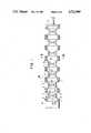
- FIG. 1is a longitudinal sectional view, taken along a line I--I in FIG. 2 showing one embodiment of the expandable and contractable arm according to this invention, the arm being in a contracted state;
- FIG. 2is a cross-sectional view taken along a line II--II in FIG. 1;
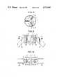
- FIG. 3is an enlarged sectional view of a portion shown in FIG. 1 bounded by a circle III;
- FIG. 4is a sectional view taken along a line IV--IV in FIG. 3;
- FIG. 5is a side view of the arm shown in FIG. 1 in its expanded state
- FIG. 6is a side view of the arm when it is bent in various directions
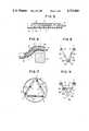
- FIG. 7is a cross-sectional view showing a modified embodiment of this invention in which three link mechanisms are arranged in an equilateral triangular configuration
- FIGS. 8, 9, 10a, 10b and 11show side views of other modifications of this invention.
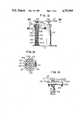
- FIG. 12is a side view, partly in section, showing a modified arm unit including three sets of double thread type expandable and contractable rods;
- FIG. 13is a sectional view taken along a line XIII--XIII. in FIG. 12;
- FIG. 14is a sectional view showing a universal joint utilized in the arm unit shown in FIG. 13;
- FIG. 15is an enlarged sectional view taken along a line XV--XV in FIG. 12;
- FIG. 16is a side view of the arm unit shown in FIG. 12 in which the upper base plate is inclined.
- FIGS. 1 through 6show a first embodiment of this invention.
- a plurality of (in this example 8) short cylindrical or annular members 1are arranged in an axial direction and adjacent annular members 1 are interconnected by at least 3 link mechanisms 2 which are equally spaced in the circumferential direction as shown in FIG. 2.
- Each link mechanism 2comprises a pair of links 2a pivotally connected by a pivot pin 2b so as to vary the angle between two links, in other words to expand and contract arm.
- the link mechanisms 2extend in the radial direction from the center of the annular member 1.
- the outer ends of respective links 2aare connected to the inner surface of respective annular members 1 through flexible or universal couplings 3.
- each flexible coupling 3is provided with a holder 4 projecting inwardly from the annular member 1 and criss-cross shaped pins 5 with their radial pins 5a pivotally connected to the holder 4.
- Connecting members 6 projecting from the ends of links 2aare pivotally connected to the circumferential pins 5b of the criss-cross shaped pins 5.
- each link 2acan incline in any direction.
- a piston-cylinder assembly 7is connected between two links 2a of each link mechanism through pivot pins 7a for expanding and contracting the link.
- the annular member 1 at one end of the armis secured to a stationary member 8, while the annular member 1 at the opposite end is secured to a detector 9 or any member to be manipulated by the arm.
- FIGS. 1-4operates as follows.
- the armcould be bent in any desired direction as shown in FIG. 6, whereby the arm can extend above an obstacle 10.
- the armcan be contracted by retracting pistons 7 of the piston-cylinder assemblies.
- the arm of this embodimentnot only can expand and contract straightforwardly but also can bend in any direction.
- FIG. 7shows a modified embodiment of this invention in which three link mechanisms are arranged in an equilateral triangle.
- each link mechanism 2is connected to each flexible joint 3 so as to form one side of the equilateral triangle.
- the armcan be contracted or expanded by actuating the pistons 7b of respective piston-cylinder assemblies.
- three link mechanisms 2are sufficient, but if desired, the number of the link mechanisms can be increased to four or more.
- FIG. 8shows another modification of the arm wherein an electric motor 12 is secured to an intermediate point of one link 2a, and a worm 13 secured to the motor shaft 12a is disposed to mesh with a worm wheel 14 mounted on one end of the other link 2a concentric with a pivot pin 2b.
- FIG. 9shows still another modification of the arm of this invention in which a threaded rod 15 is threaded through intermediate portions of respective links 2a.
- One end of the threaded rod 15is rotatably supported by a ball bearing 16 and the other end is threaded through a ball bearing shaped nut 17.
- a gear 18 secured to the threaded rod 15is driven by an electric motor 19 through the output shaft 19a thereof and a gear 20, the motor 19 being secured to link 2a.
- the angle subtended by links 2acan be varied by rotating the motor 19 in the forward or reverse direction.
- FIGS. 10a and 10bshow yet another embodiment of this invention in which a piston-cylinder assembly 7 is provided for a stationary member 8 and a flexible composite wire 21 is provided between the piston-cylinder assembly 7 and the links 2a. More particularly, the inner wire 21a of the composite wire is connected between the piston 7b and a far side link 2a while the outer wire 21b is connected between the stationary member 8 and the near link 2a. Furthermore, a compression spring 22 is interposed between the links 2a.
- a spring made of a shape memory alloyis connected between adjacent links 2a and the temperature of the spring is controlled by a heating element, not shown, to vary the length of the spring so as to open and close the links.
- FIG. 12shows one unit of a modified expandable and contractable arm of this invention.
- a plurality of unitsare connected in series to constitute an arm that can expand and contract straightforwardly or bend in any direction.
- the unit shown in FIG. 12comprises a circular base plate 101 and three or more sets of vertically extending double thread type expandable and contractable levers 102 are secured to the base plate 101 at equal circumferential spacings.
- Each lever 102comprises a stationary cylinder 103 secured to the lower base plate 101, a first threaded rod 104 and a second threaded rod 105.
- a circular upper base plate 107is pivotally connected to the upper end of the second threaded rod 105 through a flexible or universal joint 106.
- a mechanism 108 for expanding and contracting threaded rods 104 and 105is provided for the upper end of each lever 102.
- the first threaded rod 104takes the form of a hollow cylinder and its male thread 104a engages female thread 103a formed on the inside of the stationary cylinder 103.
- the male thread 105aengages the female thread 104b formed on the upper inner surface of the first threaded rod 104.
- an axial key slot 104cis provided for the first threaded rod 104.
- the drive mechanism 108comprises a worm wheel 109 surrounding the first threaded rod 104 with a small gap to rotate freely, a worm 110 meshing with the worm wheel 109 and a reversible motor 111. As shown in FIG.
- the flexible joint 106comprises a ball joint 106a secured to the upper end of the second threaded rod 105, a pin 106b slidably extending through the ball joint 106a, and L shaped flanges 106c depending from the lower surface of the upper base plate 107 to support the opposite ends of the pin 106b.
- three pins 106bare disposed in parallel and the uppermost pin 106b, as viewed in FIG. 15, is supported by a slot, not shown, of the flanges 106c to be movable in a direction perpendicular to the pin 106b.
- the upper and lower base plates 107 and 101 of adjacent arm unitsare connected together by suitable means to form an integral disc corresponding to the circular member 1 shown in FIG. 1, thus completing an expandable and contractable arm capable of operating in the same manner as that shown in FIG. 1.
- the motors 111 for respective unitsare operated for different times or at different speeds.
- the ball joint 106aslides along the pin 106b to absorb variation in the difference of the distance between the axes of pins 106b.
- this arrangementalso absorbs the variation in the distance between axes. In this manner, the arm can bend in any direction.
- the arm of this inventioncan not only expand and contract straightforwardly but also can bend in any direction, so that a detector or tool secured to the free end of the arm can readily be brought into its working position through a narrow passage.
Landscapes
- Engineering & Computer Science (AREA)
- Robotics (AREA)
- Mechanical Engineering (AREA)
- Manipulator (AREA)
- Jib Cranes (AREA)
- Tents Or Canopies (AREA)
Abstract
Description
This invention relates to an expandable, contractable and bendable arm.
In recent years, in nuclear reactors and many other industries, it has been desired to maintain, inspect and measure various parts from a remote place for avoiding danger of irradiation of radioactive substances, and for saving power.
To effect such remote operation, according to a prior art method, a manipulator or other operating device is mounted on a carriage which is controlled remotely and after bringing the carriage to a working place the manipulator is expanded or contracted to perform desired operation.
However, the carriage cannot approach an object beyond a limit because of the presence of obstacles in the working space. Moreover, as there is a limit for the length of the arm of the manipulator its workability is also limited. Further, prior art arms could not be contracted from the state in which the arm has been extended straightly, and cannot be bent.
One example of a manipulator arm which can be bent is disclosed in U.S.S.R. Inventor's Certificate No. 422580. The arm shown therein, however, cannot increase or decrease the length thereof.
It is an object of this invention to provide an improved expandable and contractable arm which can be expanded and contracted straightforwardly and can be bent in any direction.
According to this invention there is provided an expandable and contractable arm comprising a plurality of expandable and contractable units and connecting means including universal joints for serially interconnecting the units into the arm, each of the units including at least three expandable and contractable members, and means for equally or unequally expanding and contracting the members so as to increase or decrease distances between the connecting members while maintaining them in parallel or inclined with respect to each other.
In the accompanying drawings:
FIG. 1 is a longitudinal sectional view, taken along a line I--I in FIG. 2 showing one embodiment of the expandable and contractable arm according to this invention, the arm being in a contracted state;
FIG. 2 is a cross-sectional view taken along a line II--II in FIG. 1;
FIG. 3 is an enlarged sectional view of a portion shown in FIG. 1 bounded by a circle III;
FIG. 4 is a sectional view taken along a line IV--IV in FIG. 3;
FIG. 5 is a side view of the arm shown in FIG. 1 in its expanded state;
FIG. 6 is a side view of the arm when it is bent in various directions;
FIG. 7 is a cross-sectional view showing a modified embodiment of this invention in which three link mechanisms are arranged in an equilateral triangular configuration;
FIGS. 8, 9, 10a, 10b and 11 show side views of other modifications of this invention;
FIG. 12 is a side view, partly in section, showing a modified arm unit including three sets of double thread type expandable and contractable rods;
FIG. 13 is a sectional view taken along a line XIII--XIII. in FIG. 12;
FIG. 14 is a sectional view showing a universal joint utilized in the arm unit shown in FIG. 13;
FIG. 15 is an enlarged sectional view taken along a line XV--XV in FIG. 12; and
FIG. 16 is a side view of the arm unit shown in FIG. 12 in which the upper base plate is inclined.
FIGS. 1 through 6 show a first embodiment of this invention. As shown in FIGS. 1 and 2 according to this embodiment, a plurality of (in this example 8) short cylindrical or annular members 1 are arranged in an axial direction and adjacent annular members 1 are interconnected by at least 3link mechanisms 2 which are equally spaced in the circumferential direction as shown in FIG. 2. Eachlink mechanism 2 comprises a pair oflinks 2a pivotally connected by apivot pin 2b so as to vary the angle between two links, in other words to expand and contract arm. As shown in FIG. 2, thelink mechanisms 2 extend in the radial direction from the center of the annular member 1. The outer ends ofrespective links 2a are connected to the inner surface of respective annular members 1 through flexible oruniversal couplings 3. As shown in FIGS. 3 and 4, eachflexible coupling 3 is provided with aholder 4 projecting inwardly from the annular member 1 and criss-cross shapedpins 5 with theirradial pins 5a pivotally connected to theholder 4. Connectingmembers 6 projecting from the ends oflinks 2a are pivotally connected to thecircumferential pins 5b of the criss-cross shapedpins 5. With this construction, eachlink 2a can incline in any direction. A piston-cylinder assembly 7 is connected between twolinks 2a of each link mechanism through pivot pins 7a for expanding and contracting the link. The annular member 1 at one end of the arm is secured to astationary member 8, while the annular member 1 at the opposite end is secured to adetector 9 or any member to be manipulated by the arm.
The embodiment shown in FIGS. 1-4 operates as follows.
While the arm is in the contracted state as shown in FIG. 1, pressurized fluid is supplied to respective piston-cylinder assemblies 7 to cause theirpistons 7b to project wherebyrespective links 2a are gradually expanded to elongate the arm.
At this time, when three piston-cylinder assemblies 7 which are disposed at equal spacing in the circumferential direction are expanded by equal amount, the arm will be expanded linearly as shown in FIG. 5.
When the three piston-cylinder assemblies are expanded unequally the arm could be bent in any desired direction as shown in FIG. 6, whereby the arm can extend above anobstacle 10.
The arm can be contracted by retractingpistons 7 of the piston-cylinder assemblies.
As above described the arm of this embodiment not only can expand and contract straightforwardly but also can bend in any direction.
FIG. 7 shows a modified embodiment of this invention in which three link mechanisms are arranged in an equilateral triangle.
More particularly, threeflexible joints 3 are secured at an equal spacing to the inner surface of the annular member 1 throughbrackets 11 and eachlink mechanism 2 is connected to eachflexible joint 3 so as to form one side of the equilateral triangle. In this modification too, the arm can be contracted or expanded by actuating thepistons 7b of respective piston-cylinder assemblies. To relatively incline adjacent ring members 1, threelink mechanisms 2 are sufficient, but if desired, the number of the link mechanisms can be increased to four or more.
FIG. 8 shows another modification of the arm wherein anelectric motor 12 is secured to an intermediate point of onelink 2a, and aworm 13 secured to themotor shaft 12a is disposed to mesh with aworm wheel 14 mounted on one end of theother link 2a concentric with apivot pin 2b.
In this modification, as themotor 12 rotates in the forward or reverse direction, the worm wheel is rotated in the forward or reverse direction so as to change the angle subtended bylinks 2a, thus varying the spacing between adjacent annular members 1. Furthermore, according to this modification, the extent of expansion and contraction of the arm can be more finely adjusted than the previous embodiment by controlling the number of revolutions of themotor 12.
FIG. 9 shows still another modification of the arm of this invention in which a threadedrod 15 is threaded through intermediate portions ofrespective links 2a. One end of the threadedrod 15 is rotatably supported by a ball bearing 16 and the other end is threaded through a ball bearing shapednut 17. Agear 18 secured to the threadedrod 15 is driven by anelectric motor 19 through theoutput shaft 19a thereof and agear 20, themotor 19 being secured tolink 2a. In the same manner, the angle subtended bylinks 2a can be varied by rotating themotor 19 in the forward or reverse direction.
FIGS. 10a and 10b show yet another embodiment of this invention in which a piston-cylinder assembly 7 is provided for astationary member 8 and aflexible composite wire 21 is provided between the piston-cylinder assembly 7 and thelinks 2a. More particularly, the inner wire 21a of the composite wire is connected between thepiston 7b and a farside link 2a while the outer wire 21b is connected between thestationary member 8 and thenear link 2a. Furthermore, acompression spring 22 is interposed between thelinks 2a.
When thepiston 7b is retracted against the force of thecompression spring 22, the spacing between adjacent ring members 1 is decreased as shown in FIG. 10a, whereas when thepiston 7b is protruded, the spacing is increased as shown in FIG. 10b. In this modification, since the piston-cylinder assembly is secured to thestationary member 8, it is possible to decrease the weight of the arm than previous embodiments.
In another modification as shown in FIG. 11, a spring made of a shape memory alloy is connected betweenadjacent links 2a and the temperature of the spring is controlled by a heating element, not shown, to vary the length of the spring so as to open and close the links.
In the following embodiments double thread type expandable and contractable levers are substituted for the link mechanism for attaining the same object.
FIG. 12 shows one unit of a modified expandable and contractable arm of this invention. A plurality of units are connected in series to constitute an arm that can expand and contract straightforwardly or bend in any direction. The unit shown in FIG. 12 comprises acircular base plate 101 and three or more sets of vertically extending double thread type expandable andcontractable levers 102 are secured to thebase plate 101 at equal circumferential spacings. Eachlever 102 comprises astationary cylinder 103 secured to thelower base plate 101, a first threadedrod 104 and a second threadedrod 105. A circularupper base plate 107 is pivotally connected to the upper end of the second threadedrod 105 through a flexible oruniversal joint 106. Amechanism 108 for expanding and contracting threadedrods lever 102.
More particularly, the first threadedrod 104 takes the form of a hollow cylinder and itsmale thread 104a engagesfemale thread 103a formed on the inside of thestationary cylinder 103. Themale thread 105a engages thefemale thread 104b formed on the upper inner surface of the first threadedrod 104. As shown in FIG. 13, an axialkey slot 104c is provided for the first threadedrod 104. Thedrive mechanism 108 comprises aworm wheel 109 surrounding the first threadedrod 104 with a small gap to rotate freely, aworm 110 meshing with theworm wheel 109 and a reversible motor 111. As shown in FIG. 13 theworm wheel 109 and the first threadedrod 104 are coupled together by a key 112 received in thekey slot 104c. As shown in FIG. 14, the flexible joint 106 comprises a ball joint 106a secured to the upper end of the second threadedrod 105, apin 106b slidably extending through the ball joint 106a, and L shapedflanges 106c depending from the lower surface of theupper base plate 107 to support the opposite ends of thepin 106b. As shown in FIG. 15, threepins 106b are disposed in parallel and theuppermost pin 106b, as viewed in FIG. 15, is supported by a slot, not shown, of theflanges 106c to be movable in a direction perpendicular to thepin 106b.
The upper andlower base plates
More particularly, when themotors 110 ofrespective drive mechanism 108 are rotated in the same direction for the same time, all threadedrods 105 of respective arm units are elongated or contracted by the same amount so that the arm as a whole is expanded or contracted straightforwardly with upper andlower base plates
To incline theupper base plate 107, that is to bend the arm, the motors 111 for respective units are operated for different times or at different speeds. As theupper base plate 107 is inclined the ball joint 106a slides along thepin 106b to absorb variation in the difference of the distance between the axes ofpins 106b. As above described since eachpin 106b is slidably received in slots of theflanges 106c, this arrangement also absorbs the variation in the distance between axes. In this manner, the arm can bend in any direction.
As above described, the arm of this invention can not only expand and contract straightforwardly but also can bend in any direction, so that a detector or tool secured to the free end of the arm can readily be brought into its working position through a narrow passage.
Claims (10)
1. An expandable and contractable arm comprising:
a plurality of independently expandable and contractable units; and
connecting means including universal joints for serially interconnecting said units into said arm;
each of said units comprising a pair of disc members disposed at opposite ends of said unit, at least three link mechanisms each comprising two links, the inner ends of said links being connected together by a pin and the outer ends of said links being connected to said pair of disc members through said universal joints and means for relatively rotating said two links about said pin independently from the other said link mechanisms within said unit thereby expanding and contracting each unit independently from another unit when said at least three link mechanisms are operated equally, and bending each unit independently from another unit when said at least three link mechanisms are operated unequally.
2. The arm according to claim 1 wherein said unit comprises three link mechanisms disposed in an equilateral triangle.
3. The arm according to claim 1 wherein said at least three link mechanisms are provided to extend in the radial direction of said disc members.
4. The arm according to claim 1 wherein said rotating means comprises a motor secured to an intermediate point of a first one of said two links, and a worm wheel connected to the inner end of a second one of said two links concentric with said pin and meshing with a worm driven by said motor.
5. The arm according to claim 1 wherein said rotating means comprises a threaded rod having an end threaded through a first one of said two links, a gear secured to an other end of said threaded rod, and a motor secured to a second one of said two links, for driving said gear.
6. The arm according to claim 1 wherein said rotating means comprises a spring made of a shape memory alloy.
7. The arm according to claim 6, wherein said spring is secured to an intermediate point of each of said two connected links and the temperature of said spring is controlled by a heating element which regulates the length of said spring.
8. The arm according to claim 1, further comprising a stationary member secured to a first unit and a manipulatable member secured to an end unit.
9. The arm according to claim 1, wherein said rotating means comprises a piston-cylinder assembly activated by pressurized fluid.
10. The arm according to claim 9 wherein said rotating means comprises a compression spring interposed between said two links, and said piston-cylinder assembly further comprises a cylinder secured to a stationary member, and a flexible composite wire, one wire of said composite wire being connected between said stationary member and a first one of said two links and the other wire of said composite wire being connected between a piston of said piston-cylinder assembly and a second one of said two links.
Applications Claiming Priority (4)
| Application Number | Priority Date | Filing Date | Title |
|---|---|---|---|
| JP58-157475 | 1983-08-29 | ||
| JP15747583AJPS6048292A (en) | 1983-08-29 | 1983-08-29 | arm mechanism |
| JP6488084AJPS60208664A (en) | 1984-03-31 | 1984-03-31 | Arm mechanism |
| JP59-64880 | 1984-03-31 |
Related Child Applications (1)
| Application Number | Title | Priority Date | Filing Date |
|---|---|---|---|
| US06/940,941DivisionUS4818175A (en) | 1983-08-29 | 1986-12-12 | Expandable and contractible arms |
Publications (1)
| Publication Number | Publication Date |
|---|---|
| US4712969Atrue US4712969A (en) | 1987-12-15 |
Family
ID=26406006
Family Applications (2)
| Application Number | Title | Priority Date | Filing Date |
|---|---|---|---|
| US06/643,793Expired - Fee RelatedUS4712969A (en) | 1983-08-29 | 1984-08-24 | Expandable and contractable arms |
| US06/940,941Expired - Fee RelatedUS4818175A (en) | 1983-08-29 | 1986-12-12 | Expandable and contractible arms |
Family Applications After (1)
| Application Number | Title | Priority Date | Filing Date |
|---|---|---|---|
| US06/940,941Expired - Fee RelatedUS4818175A (en) | 1983-08-29 | 1986-12-12 | Expandable and contractible arms |
Country Status (4)
| Country | Link |
|---|---|
| US (2) | US4712969A (en) |
| DE (1) | DE3431453A1 (en) |
| FR (1) | FR2550985B1 (en) |
| GB (1) | GB2145691B (en) |
Cited By (61)
| Publication number | Priority date | Publication date | Assignee | Title |
|---|---|---|---|---|
| US4848179A (en)* | 1988-02-16 | 1989-07-18 | Trw Inc. | Flexidigit robotic manipulator |
| US4949585A (en)* | 1987-11-20 | 1990-08-21 | Rockwell-Cim | Telescopic screw jack for the adjustment of an element such as a vehicle seat |
| US5129279A (en)* | 1991-02-28 | 1992-07-14 | Rennex Brian G | Flexible robotic limb |
| US5297443A (en)* | 1992-07-07 | 1994-03-29 | Wentz John D | Flexible positioning appendage |
| US5312152A (en)* | 1991-10-23 | 1994-05-17 | Martin Marietta Corporation | Shape memory metal actuated separation device |
| US5344506A (en)* | 1991-10-23 | 1994-09-06 | Martin Marietta Corporation | Shape memory metal actuator and cable cutter |
| US5392663A (en)* | 1991-08-26 | 1995-02-28 | The Ingersoll Milling Machine Company | Octahedral machine tool frame |
| US5560258A (en)* | 1993-01-08 | 1996-10-01 | Fmc Corporation | Release mechanism for use with a remote tool |
| WO2001060214A2 (en) | 2000-02-15 | 2001-08-23 | The Procter & Gamble Company | Active change aids for external articles |
| US6316899B1 (en)* | 1994-09-07 | 2001-11-13 | Polytechnic University | Apparatus for reducing vibration inputs to a device and/or for micropositioning |
| US6575691B1 (en)* | 1998-07-22 | 2003-06-10 | Tokyo Electron Limited | Transfer arm |
| US20050028660A1 (en)* | 2003-08-06 | 2005-02-10 | Chang Chin-Chin | Circular sawing machine having a link mechanism |
| US6858005B2 (en) | 2000-04-03 | 2005-02-22 | Neo Guide Systems, Inc. | Tendon-driven endoscope and methods of insertion |
| US20060156851A1 (en)* | 2004-12-02 | 2006-07-20 | Jacobsen Stephen C | Mechanical serpentine device |
| US20080213077A1 (en)* | 2007-03-01 | 2008-09-04 | Honda Motor Co., Ltd. | Articulated robot |
| US20080302200A1 (en)* | 2007-06-06 | 2008-12-11 | Tobey Wayland E | Modular hybrid snake arm |
| US20090044654A1 (en)* | 2005-07-20 | 2009-02-19 | Lucio Vaccani | Module for the Manufacturing of Automated Moving Structures and Automated Moving Modular Structure |
| WO2010001124A3 (en)* | 2008-07-02 | 2010-05-06 | Oliver Crispin Robotics Limited | Release mechanism for robotic arms |
| US8002365B2 (en) | 2006-11-13 | 2011-08-23 | Raytheon Company | Conformable track assembly for a robotic crawler |
| US8002716B2 (en) | 2007-05-07 | 2011-08-23 | Raytheon Company | Method for manufacturing a complex structure |
| US8042630B2 (en) | 2006-11-13 | 2011-10-25 | Raytheon Company | Serpentine robotic crawler |
| US8062212B2 (en) | 2000-04-03 | 2011-11-22 | Intuitive Surgical Operations, Inc. | Steerable endoscope and improved method of insertion |
| US8083879B2 (en) | 2005-11-23 | 2011-12-27 | Intuitive Surgical Operations, Inc. | Non-metallic, multi-strand control cable for steerable instruments |
| US8185241B2 (en) | 2006-11-13 | 2012-05-22 | Raytheon Company | Tracked robotic crawler having a moveable arm |
| US8182418B2 (en) | 2008-02-25 | 2012-05-22 | Intuitive Surgical Operations, Inc. | Systems and methods for articulating an elongate body |
| US8317555B2 (en) | 2009-06-11 | 2012-11-27 | Raytheon Company | Amphibious robotic crawler |
| US8361090B2 (en) | 2002-01-09 | 2013-01-29 | Intuitive Surgical Operations, Inc. | Apparatus and method for endoscopic colectomy |
| US20130031764A1 (en)* | 2011-08-03 | 2013-02-07 | The Boeing Company | Robot including telescopic assemblies for positioning an end effector |
| US8392036B2 (en) | 2009-01-08 | 2013-03-05 | Raytheon Company | Point and go navigation system and method |
| US8393422B1 (en) | 2012-05-25 | 2013-03-12 | Raytheon Company | Serpentine robotic crawler |
| US8517923B2 (en) | 2000-04-03 | 2013-08-27 | Intuitive Surgical Operations, Inc. | Apparatus and methods for facilitating treatment of tissue via improved delivery of energy based and non-energy based modalities |
| DE102012008559A1 (en)* | 2012-04-04 | 2013-10-10 | Pi4_Robotics Gmbh | Robot arm module for robot arm, has module body, three articulated joint units on module body and three connection units which are arranged on module body by one of articulated joint units in pivotable manner |
| US8568299B2 (en) | 2006-05-19 | 2013-10-29 | Intuitive Surgical Operations, Inc. | Methods and apparatus for displaying three-dimensional orientation of a steerable distal tip of an endoscope |
| US8571711B2 (en) | 2007-07-10 | 2013-10-29 | Raytheon Company | Modular robotic crawler |
| CN103895012A (en)* | 2014-04-25 | 2014-07-02 | 清华大学 | Trunk-simulating mechanical arm unit device |
| US8845524B2 (en) | 2000-04-03 | 2014-09-30 | Intuitive Surgical Operations, Inc. | Steerable segmented endoscope and method of insertion |
| US8882657B2 (en) | 2003-03-07 | 2014-11-11 | Intuitive Surgical Operations, Inc. | Instrument having radio frequency identification systems and methods for use |
| US8888688B2 (en) | 2000-04-03 | 2014-11-18 | Intuitive Surgical Operations, Inc. | Connector device for a controllable instrument |
| US8935014B2 (en) | 2009-06-11 | 2015-01-13 | Sarcos, Lc | Method and system for deploying a surveillance network |
| US9031698B2 (en) | 2012-10-31 | 2015-05-12 | Sarcos Lc | Serpentine robotic crawler |
| US20150141756A1 (en)* | 2012-05-12 | 2015-05-21 | Massachusetts Institute Of Technology | Continuum style manipulator actuated with phase change media |
| FR3013586A1 (en)* | 2013-11-27 | 2015-05-29 | Assistive Robotic Technologies | ARTICULATED MOTORIZED MODULE, JOINT COMPRISING MULTIPLE MODULES AND EXOSQUELET COMPRISING SEVERAL ARTICULATIONS |
| US9220398B2 (en) | 2007-10-11 | 2015-12-29 | Intuitive Surgical Operations, Inc. | System for managing Bowden cables in articulating instruments |
| US9409292B2 (en) | 2013-09-13 | 2016-08-09 | Sarcos Lc | Serpentine robotic crawler for performing dexterous operations |
| CN106078691A (en)* | 2016-07-28 | 2016-11-09 | 长沙学院 | Flexible coding system wrist device and control method |
| US9566711B2 (en) | 2014-03-04 | 2017-02-14 | Sarcos Lc | Coordinated robotic control |
| US9919434B1 (en)* | 2012-11-14 | 2018-03-20 | Commissariat A L'energie Atomique Et Aux Energies Alternatives | Articulated arm |
| CN108356797A (en)* | 2018-02-02 | 2018-08-03 | 西安电子科技大学 | A kind of spring-rope drive lacking space mechanism arm device |
| US20190054637A1 (en)* | 2017-08-21 | 2019-02-21 | Massachusetts Institute Of Technology | Extending robotic arm |
| CN109476019A (en)* | 2016-07-26 | 2019-03-15 | Groove X 株式会社 | multi-joint robot |
| US20190120346A1 (en)* | 2016-07-06 | 2019-04-25 | Sony Corporation | Expansion/contraction mechanism and four-legged robot |
| EP2961577B1 (en)* | 2013-02-26 | 2019-11-06 | Ahmad Kamal Bakir | Manipulator arm module |
| US10512392B2 (en) | 2008-02-06 | 2019-12-24 | Intuitive Surgical Operations, Inc. | Segmented instrument having braking capabilities |
| CN111015645A (en)* | 2019-12-25 | 2020-04-17 | 中国科学院沈阳自动化研究所 | Rope-driven continuous flexible manipulator |
| US10730179B2 (en) | 2018-05-29 | 2020-08-04 | General Electric Company | Robotic arm assembly construction |
| US11096563B2 (en) | 2005-11-22 | 2021-08-24 | Intuitive Surgical Operations, Inc. | Method of determining the shape of a bendable instrument |
| CN113580195A (en)* | 2021-08-11 | 2021-11-02 | 上海大学 | Many closed loops of wire winding thin wall can open and receive arm |
| US20220040854A1 (en)* | 2020-04-01 | 2022-02-10 | Dalian University Of Technology | Multi-degree-of-freedom continuum robot with flexible target grasping function |
| US11331814B2 (en)* | 2018-09-13 | 2022-05-17 | Kinova Inc. | Articulated mechanism with protective sleeve at joint |
| US11491645B2 (en)* | 2019-06-07 | 2022-11-08 | Massachusetts Institute Of Technology | Scissor linkage design and method of operation |
| US12311550B2 (en) | 2020-12-31 | 2025-05-27 | Sarcos Corp. | Smart control system for a robotic device |
Families Citing this family (48)
| Publication number | Priority date | Publication date | Assignee | Title |
|---|---|---|---|---|
| EP0160305B1 (en)* | 1984-05-02 | 1989-10-25 | Kabushiki Kaisha Tokuda Seisakusho | Carrying device |
| DE8511727U1 (en)* | 1985-04-19 | 1986-05-22 | Krueger-Beuster, Helmut, 2420 Eutin | Joint element for manipulators |
| DE8511729U1 (en)* | 1985-04-19 | 1985-11-28 | Krueger-Beuster, Helmut, 2420 Eutin | Joint element for manipulators |
| CH672089A5 (en)* | 1985-12-16 | 1989-10-31 | Sogeva Sa | |
| CH668379A5 (en)* | 1986-08-07 | 1988-12-30 | Ernst Ochsner | HOLDING DEVICE FOR AN OBJECT TO BE TREATED ALL-SURFACE. |
| DE3738939A1 (en)* | 1987-11-17 | 1989-06-01 | Krueger Beuster Helmut | Joint element for manipulators or the like |
| JP2617530B2 (en)* | 1988-09-02 | 1997-06-04 | 学校法人早稲田大学 | Bulb flakes planting hand |
| FR2681806B1 (en)* | 1991-09-11 | 1993-12-31 | Maurice Gabillet | ARTICULATION FOR ROBOTIC ARMS. |
| US5263382A (en)* | 1992-04-13 | 1993-11-23 | Hughes Aircraft Company | Six Degrees of freedom motion device |
| US5692412A (en)* | 1993-11-15 | 1997-12-02 | Ross-Hime Designs, Incorporated | Robotic manipulator |
| US5722304A (en)* | 1994-03-01 | 1998-03-03 | Honeywell Inc. | Linear actuator |
| US5733096A (en)* | 1995-09-13 | 1998-03-31 | Silicon Valley Group, Inc. | Multi-stage telescoping structure |
| DE10151754B4 (en)* | 2001-10-19 | 2005-01-20 | Klaus Priv.-Doz. Dr. med. Seide | length adjusting |
| US7165620B2 (en)* | 2002-12-23 | 2007-01-23 | Fmc Technologies, Inc. | Wellhead completion system having a horizontal control penetrator and method of using same |
| DE102005040204A1 (en)* | 2005-08-19 | 2007-02-22 | Danaher Linear Gmbh | Ball screw and method for moving a threaded spindle in a ball screw |
| US20080215185A1 (en)* | 2006-11-13 | 2008-09-04 | Jacobsen Stephen C | Unmanned ground robotic vehicle having an alternatively extendible and retractable sensing appendage |
| EP2549165B1 (en)* | 2006-11-13 | 2014-03-12 | Raytheon Company | Serpentine robotic crawler |
| WO2008150630A2 (en)* | 2007-05-08 | 2008-12-11 | Raytheon Sarcos, Llc | Variable primitive mapping for a robotic crawler |
| CN101778756B (en)* | 2007-07-10 | 2013-01-23 | 雷神萨科斯公司 | Snake-like robotic crawler with continuous tracks |
| ES2387146B8 (en)* | 2010-06-21 | 2013-12-04 | Universidad Miguel Hernández De Elche | MECHANISM AND ARTICULATED MODULE |
| CN102092047A (en)* | 2010-12-24 | 2011-06-15 | 杭州厚达自动化系统有限公司 | Loading and unloading mechanical hand for kilowatt-hour meter |
| US9352185B2 (en)* | 2011-07-12 | 2016-05-31 | Icon Health & Fitness, Inc. | Exercise device with inclination adjusting mechanism |
| WO2014153158A1 (en) | 2013-03-14 | 2014-09-25 | Icon Health & Fitness, Inc. | Strength training apparatus with flywheel and related methods |
| CN105848733B (en) | 2013-12-26 | 2018-02-13 | 爱康保健健身有限公司 | Magnetic resistance mechanism in hawser apparatus |
| US10433612B2 (en) | 2014-03-10 | 2019-10-08 | Icon Health & Fitness, Inc. | Pressure sensor to quantify work |
| WO2015191445A1 (en) | 2014-06-09 | 2015-12-17 | Icon Health & Fitness, Inc. | Cable system incorporated into a treadmill |
| CN104476533B (en)* | 2014-11-27 | 2017-01-11 | 清华大学 | Master-slave control flexible continuum robot device and control method thereof |
| US10258828B2 (en) | 2015-01-16 | 2019-04-16 | Icon Health & Fitness, Inc. | Controls for an exercise device |
| US10071303B2 (en) | 2015-08-26 | 2018-09-11 | Malibu Innovations, LLC | Mobilized cooler device with fork hanger assembly |
| US10953305B2 (en) | 2015-08-26 | 2021-03-23 | Icon Health & Fitness, Inc. | Strength exercise mechanisms |
| US10493349B2 (en) | 2016-03-18 | 2019-12-03 | Icon Health & Fitness, Inc. | Display on exercise device |
| US10625137B2 (en) | 2016-03-18 | 2020-04-21 | Icon Health & Fitness, Inc. | Coordinated displays in an exercise device |
| US10293211B2 (en) | 2016-03-18 | 2019-05-21 | Icon Health & Fitness, Inc. | Coordinated weight selection |
| US10272317B2 (en) | 2016-03-18 | 2019-04-30 | Icon Health & Fitness, Inc. | Lighted pace feature in a treadmill |
| US10561894B2 (en) | 2016-03-18 | 2020-02-18 | Icon Health & Fitness, Inc. | Treadmill with removable supports |
| US10252109B2 (en) | 2016-05-13 | 2019-04-09 | Icon Health & Fitness, Inc. | Weight platform treadmill |
| US10807659B2 (en) | 2016-05-27 | 2020-10-20 | Joseph L. Pikulski | Motorized platforms |
| US10441844B2 (en) | 2016-07-01 | 2019-10-15 | Icon Health & Fitness, Inc. | Cooling systems and methods for exercise equipment |
| US10471299B2 (en) | 2016-07-01 | 2019-11-12 | Icon Health & Fitness, Inc. | Systems and methods for cooling internal exercise equipment components |
| US10500473B2 (en) | 2016-10-10 | 2019-12-10 | Icon Health & Fitness, Inc. | Console positioning |
| US10376736B2 (en) | 2016-10-12 | 2019-08-13 | Icon Health & Fitness, Inc. | Cooling an exercise device during a dive motor runway condition |
| US10661114B2 (en) | 2016-11-01 | 2020-05-26 | Icon Health & Fitness, Inc. | Body weight lift mechanism on treadmill |
| TWI646997B (en) | 2016-11-01 | 2019-01-11 | 美商愛康運動與健康公司 | Distance sensor for console positioning |
| TWI680782B (en) | 2016-12-05 | 2020-01-01 | 美商愛康運動與健康公司 | Offsetting treadmill deck weight during operation |
| CN107443364B (en)* | 2017-08-04 | 2023-08-01 | 涂超 | Scalable twistable modularization unit structure |
| US11451108B2 (en) | 2017-08-16 | 2022-09-20 | Ifit Inc. | Systems and methods for axial impact resistance in electric motors |
| US10729965B2 (en) | 2017-12-22 | 2020-08-04 | Icon Health & Fitness, Inc. | Audible belt guide in a treadmill |
| CN109262600B (en)* | 2018-10-17 | 2022-02-22 | 尉长虹 | Telescopic soft mechanical device |
Citations (32)
| Publication number | Priority date | Publication date | Assignee | Title |
|---|---|---|---|---|
| US2286571A (en)* | 1938-04-22 | 1942-06-16 | Willard L V Pollard | Position-controlling apparatus |
| FR1074805A (en)* | 1952-01-28 | 1954-10-08 | Lifting device | |
| US2725578A (en)* | 1952-03-28 | 1955-12-06 | Keller-Erne Lina | Transporting devices for invalids for use in bathtubs and like receptacles |
| GB797882A (en)* | 1955-05-26 | 1958-07-09 | Rolls Royce | Improvements in or relating to manipulating devices |
| GB879098A (en)* | 1957-10-10 | 1961-10-04 | Johann Wilhelm Ludowici | Improvements in and relating to lifting devices |
| US3034765A (en)* | 1957-07-24 | 1962-05-15 | Ludowici Johann Wilhelm | Lifting devices |
| US3160290A (en)* | 1963-03-19 | 1964-12-08 | Kentner B Wilson | Servo manipulator arm |
| US3261479A (en)* | 1962-12-26 | 1966-07-19 | Samuel W Baker | Manipulating devices |
| FR1500113A (en)* | 1966-07-13 | 1967-11-03 | Siersatom S A | Multi-orientation arm |
| US3580099A (en)* | 1969-09-24 | 1971-05-25 | Gen Electric | Articulating mechanism |
| US3631737A (en)* | 1970-09-18 | 1972-01-04 | Nasa | Remote control manipulator for zero gravity environment |
| SU393083A1 (en)* | 1971-06-14 | 1973-08-10 | Всесоюзный научно исследовательский институт монтажным , специальным строительным работам | MECHANISM OF THE HAMPER OF THE MANIPULATOR |
| SU422580A2 (en)* | 1972-05-04 | 1974-04-05 | В. Д. Абезгауз | MECHANISM OF THE HINGE OF MANIPULATORS P TB |
| SU528194A2 (en)* | 1975-04-10 | 1976-09-15 | Предприятие П/Я В-2190 | Manipulator |
| US4070807A (en)* | 1977-01-12 | 1978-01-31 | Smith Raymond E Jun | Aerial lift |
| US4088203A (en)* | 1976-11-03 | 1978-05-09 | Smith Raymond E Jun | Adjustable scaffold |
| FR2378612A1 (en)* | 1977-01-28 | 1978-08-25 | Renault | POLYARTICLE ARM FOR ROBOT OR AUTOMATE |
| GB1554738A (en)* | 1976-10-26 | 1979-10-31 | Delta Materials Research Ltd | Methods of and systems for environmental temperature control |
| SU697315A1 (en)* | 1978-05-30 | 1979-11-15 | Днепропетровское Отделение Института Механики Ан Украинской Сср | Manipulator arm |
| SU770779A1 (en)* | 1978-12-07 | 1980-10-15 | За витель Ю.В.Панов | Manipulator actuating member |
| SU837845A1 (en)* | 1974-09-30 | 1981-06-15 | Всесоюзный Проектно-Технологическийинститут Тяжелого Машиностроения | Manipulator's mechanical arm |
| SU861061A1 (en)* | 1979-11-11 | 1981-09-07 | Предприятие П/Я Р-6930 | Manipulator |
| SU946922A1 (en)* | 1979-12-10 | 1982-07-30 | Тбилисское Станкостроительное Производственное Объединение | Manipulator hinge |
| SU1007959A1 (en)* | 1981-07-17 | 1983-03-30 | Кишиневский политехнический институт им.С.Лазо | Manipulator arm |
| US4393728A (en)* | 1979-03-16 | 1983-07-19 | Robotgruppen Hb | Flexible arm, particularly a robot arm |
| SU1077780A1 (en)* | 1981-11-02 | 1984-03-07 | Институт Систем Управления Ан Гсср | Manipulator |
| GB2134483A (en)* | 1983-02-10 | 1984-08-15 | Atomic Energy Authority Uk | Manipulators |
| US4489826A (en)* | 1982-02-05 | 1984-12-25 | Philip Dubson | Adjustable apparatus |
| US4494417A (en)* | 1979-03-16 | 1985-01-22 | Robotgruppen Hb | Flexible arm, particularly a robot arm |
| US4551061A (en)* | 1983-04-18 | 1985-11-05 | Olenick Ralph W | Flexible, extensible robot arm |
| SU1194672A1 (en)* | 1983-11-23 | 1985-11-30 | Институт Машиноведения Им.А.А.Благонравова | Three-dimensional mechanism |
| US4566843A (en)* | 1982-09-22 | 1986-01-28 | Hitachi, Ltd. | Multiarticulated manipulator |
Family Cites Families (10)
| Publication number | Priority date | Publication date | Assignee | Title |
|---|---|---|---|---|
| US2766079A (en)* | 1952-05-09 | 1956-10-09 | William H Browne | Rod end bearing |
| US3395436A (en)* | 1964-03-23 | 1968-08-06 | Donald L. Sullivan | Art of rod-end bearing manufacture |
| US3438661A (en)* | 1966-07-08 | 1969-04-15 | Torrington Co | Ball bushing rod end and method of making same |
| US3371551A (en)* | 1966-09-01 | 1968-03-05 | Duff Norton Co | Nut and screw mechanism |
| US3404580A (en)* | 1967-04-18 | 1968-10-08 | Sargent Industries | Ball screw actuator |
| US3404581A (en)* | 1967-04-18 | 1968-10-08 | Sargent Industries | Ball screw actuator |
| GB1374997A (en)* | 1971-10-11 | 1974-11-20 | Int Research & Dev Co Ltd | Hydraulically-operated manipulators or actuators |
| PT77732B (en)* | 1982-12-16 | 1986-03-27 | Cyber Robotics Ltd | Robotic limb |
| DE3400362A1 (en)* | 1983-01-12 | 1984-09-13 | Helmut 2420 Eutin Krueger-Beuster | Hydraulic jointed arm |
| SU1222538A1 (en)* | 1984-06-15 | 1986-04-07 | Институт Машиноведения Им.А.А.Благонравова | Coordinate spatial mechanism (versions) |
- 1984
- 1984-08-22GBGB08421343Apatent/GB2145691B/ennot_activeExpired
- 1984-08-24USUS06/643,793patent/US4712969A/ennot_activeExpired - Fee Related
- 1984-08-27DEDE3431453Apatent/DE3431453A1/enactiveGranted
- 1984-08-27FRFR848413249Apatent/FR2550985B1/ennot_activeExpired - Lifetime
- 1986
- 1986-12-12USUS06/940,941patent/US4818175A/ennot_activeExpired - Fee Related
Patent Citations (32)
| Publication number | Priority date | Publication date | Assignee | Title |
|---|---|---|---|---|
| US2286571A (en)* | 1938-04-22 | 1942-06-16 | Willard L V Pollard | Position-controlling apparatus |
| FR1074805A (en)* | 1952-01-28 | 1954-10-08 | Lifting device | |
| US2725578A (en)* | 1952-03-28 | 1955-12-06 | Keller-Erne Lina | Transporting devices for invalids for use in bathtubs and like receptacles |
| GB797882A (en)* | 1955-05-26 | 1958-07-09 | Rolls Royce | Improvements in or relating to manipulating devices |
| US3034765A (en)* | 1957-07-24 | 1962-05-15 | Ludowici Johann Wilhelm | Lifting devices |
| GB879098A (en)* | 1957-10-10 | 1961-10-04 | Johann Wilhelm Ludowici | Improvements in and relating to lifting devices |
| US3261479A (en)* | 1962-12-26 | 1966-07-19 | Samuel W Baker | Manipulating devices |
| US3160290A (en)* | 1963-03-19 | 1964-12-08 | Kentner B Wilson | Servo manipulator arm |
| FR1500113A (en)* | 1966-07-13 | 1967-11-03 | Siersatom S A | Multi-orientation arm |
| US3580099A (en)* | 1969-09-24 | 1971-05-25 | Gen Electric | Articulating mechanism |
| US3631737A (en)* | 1970-09-18 | 1972-01-04 | Nasa | Remote control manipulator for zero gravity environment |
| SU393083A1 (en)* | 1971-06-14 | 1973-08-10 | Всесоюзный научно исследовательский институт монтажным , специальным строительным работам | MECHANISM OF THE HAMPER OF THE MANIPULATOR |
| SU422580A2 (en)* | 1972-05-04 | 1974-04-05 | В. Д. Абезгауз | MECHANISM OF THE HINGE OF MANIPULATORS P TB |
| SU837845A1 (en)* | 1974-09-30 | 1981-06-15 | Всесоюзный Проектно-Технологическийинститут Тяжелого Машиностроения | Manipulator's mechanical arm |
| SU528194A2 (en)* | 1975-04-10 | 1976-09-15 | Предприятие П/Я В-2190 | Manipulator |
| GB1554738A (en)* | 1976-10-26 | 1979-10-31 | Delta Materials Research Ltd | Methods of and systems for environmental temperature control |
| US4088203A (en)* | 1976-11-03 | 1978-05-09 | Smith Raymond E Jun | Adjustable scaffold |
| US4070807A (en)* | 1977-01-12 | 1978-01-31 | Smith Raymond E Jun | Aerial lift |
| FR2378612A1 (en)* | 1977-01-28 | 1978-08-25 | Renault | POLYARTICLE ARM FOR ROBOT OR AUTOMATE |
| SU697315A1 (en)* | 1978-05-30 | 1979-11-15 | Днепропетровское Отделение Института Механики Ан Украинской Сср | Manipulator arm |
| SU770779A1 (en)* | 1978-12-07 | 1980-10-15 | За витель Ю.В.Панов | Manipulator actuating member |
| US4393728A (en)* | 1979-03-16 | 1983-07-19 | Robotgruppen Hb | Flexible arm, particularly a robot arm |
| US4494417A (en)* | 1979-03-16 | 1985-01-22 | Robotgruppen Hb | Flexible arm, particularly a robot arm |
| SU861061A1 (en)* | 1979-11-11 | 1981-09-07 | Предприятие П/Я Р-6930 | Manipulator |
| SU946922A1 (en)* | 1979-12-10 | 1982-07-30 | Тбилисское Станкостроительное Производственное Объединение | Manipulator hinge |
| SU1007959A1 (en)* | 1981-07-17 | 1983-03-30 | Кишиневский политехнический институт им.С.Лазо | Manipulator arm |
| SU1077780A1 (en)* | 1981-11-02 | 1984-03-07 | Институт Систем Управления Ан Гсср | Manipulator |
| US4489826A (en)* | 1982-02-05 | 1984-12-25 | Philip Dubson | Adjustable apparatus |
| US4566843A (en)* | 1982-09-22 | 1986-01-28 | Hitachi, Ltd. | Multiarticulated manipulator |
| GB2134483A (en)* | 1983-02-10 | 1984-08-15 | Atomic Energy Authority Uk | Manipulators |
| US4551061A (en)* | 1983-04-18 | 1985-11-05 | Olenick Ralph W | Flexible, extensible robot arm |
| SU1194672A1 (en)* | 1983-11-23 | 1985-11-30 | Институт Машиноведения Им.А.А.Благонравова | Three-dimensional mechanism |
Non-Patent Citations (2)
| Title |
|---|
| Rosheim A New Pitch Yaw Roll Mechanical Robot Wrist Actuator Jun. 1985 21 pgs. Soc. of Manuf. Eng.* |
| Rosheim--"A New Pitch-Yaw-Roll Mechanical Robot Wrist Actuator"--Jun. 1985--21 pgs.--Soc. of Manuf. Eng. |
Cited By (108)
| Publication number | Priority date | Publication date | Assignee | Title |
|---|---|---|---|---|
| US4949585A (en)* | 1987-11-20 | 1990-08-21 | Rockwell-Cim | Telescopic screw jack for the adjustment of an element such as a vehicle seat |
| US4848179A (en)* | 1988-02-16 | 1989-07-18 | Trw Inc. | Flexidigit robotic manipulator |
| US5129279A (en)* | 1991-02-28 | 1992-07-14 | Rennex Brian G | Flexible robotic limb |
| US5392663A (en)* | 1991-08-26 | 1995-02-28 | The Ingersoll Milling Machine Company | Octahedral machine tool frame |
| US5312152A (en)* | 1991-10-23 | 1994-05-17 | Martin Marietta Corporation | Shape memory metal actuated separation device |
| US5344506A (en)* | 1991-10-23 | 1994-09-06 | Martin Marietta Corporation | Shape memory metal actuator and cable cutter |
| US5297443A (en)* | 1992-07-07 | 1994-03-29 | Wentz John D | Flexible positioning appendage |
| US5560258A (en)* | 1993-01-08 | 1996-10-01 | Fmc Corporation | Release mechanism for use with a remote tool |
| US6316899B1 (en)* | 1994-09-07 | 2001-11-13 | Polytechnic University | Apparatus for reducing vibration inputs to a device and/or for micropositioning |
| US6884019B2 (en) | 1998-07-22 | 2005-04-26 | Tokyo Electron Limited | Conveying arm |
| US6575691B1 (en)* | 1998-07-22 | 2003-06-10 | Tokyo Electron Limited | Transfer arm |
| WO2001060214A2 (en) | 2000-02-15 | 2001-08-23 | The Procter & Gamble Company | Active change aids for external articles |
| US10736490B2 (en) | 2000-04-03 | 2020-08-11 | Intuitive Surgical Operations, Inc. | Connector device for a controllable instrument |
| US8827894B2 (en) | 2000-04-03 | 2014-09-09 | Intuitive Surgical Operations, Inc. | Steerable endoscope and improved method of insertion |
| US8641602B2 (en) | 2000-04-03 | 2014-02-04 | Intuitive Surgical Operations, Inc. | Steerable endoscope and improved method of insertion |
| US12076102B2 (en) | 2000-04-03 | 2024-09-03 | Intuitive Surgical Operations, Inc. | Connector device for a controllable instrument |
| US8517923B2 (en) | 2000-04-03 | 2013-08-27 | Intuitive Surgical Operations, Inc. | Apparatus and methods for facilitating treatment of tissue via improved delivery of energy based and non-energy based modalities |
| US9427282B2 (en) | 2000-04-03 | 2016-08-30 | Intuitive Surgical Operations, Inc. | Apparatus and methods for facilitating treatment of tissue via improved delivery of energy based and non-energy based modalities |
| US11026564B2 (en) | 2000-04-03 | 2021-06-08 | Intuitive Surgical Operations, Inc. | Apparatus and methods for facilitating treatment of tissue via improved delivery of energy based and non-energy based modalities |
| US10327625B2 (en) | 2000-04-03 | 2019-06-25 | Intuitive Surgical Operations, Inc. | Apparatus and methods for facilitating treatment of tissue via improved delivery of energy based and non-energy based modalities |
| US9138132B2 (en) | 2000-04-03 | 2015-09-22 | Intuitive Surgical Operations, Inc. | Steerable endoscope and improved method of insertion |
| US8888688B2 (en) | 2000-04-03 | 2014-11-18 | Intuitive Surgical Operations, Inc. | Connector device for a controllable instrument |
| US10105036B2 (en) | 2000-04-03 | 2018-10-23 | Intuitive Surgical Operations, Inc. | Connector device for a controllable instrument |
| US9808140B2 (en) | 2000-04-03 | 2017-11-07 | Intuitive Surgical Operations, Inc. | Steerable segmented endoscope and method of insertion |
| US8062212B2 (en) | 2000-04-03 | 2011-11-22 | Intuitive Surgical Operations, Inc. | Steerable endoscope and improved method of insertion |
| US8845524B2 (en) | 2000-04-03 | 2014-09-30 | Intuitive Surgical Operations, Inc. | Steerable segmented endoscope and method of insertion |
| US8834354B2 (en) | 2000-04-03 | 2014-09-16 | Intuitive Surgical Operations, Inc. | Steerable endoscope and improved method of insertion |
| US6858005B2 (en) | 2000-04-03 | 2005-02-22 | Neo Guide Systems, Inc. | Tendon-driven endoscope and methods of insertion |
| US10893794B2 (en) | 2000-04-03 | 2021-01-19 | Intuitive Surgical Operations, Inc. | Steerable endoscope and improved method of insertion |
| US8721530B2 (en) | 2000-04-03 | 2014-05-13 | Intuitive Surgical Operations, Inc. | Tendon-driven endoscope and methods of use |
| US8361090B2 (en) | 2002-01-09 | 2013-01-29 | Intuitive Surgical Operations, Inc. | Apparatus and method for endoscopic colectomy |
| US10349816B2 (en) | 2002-01-09 | 2019-07-16 | Intuitive Surgical Operations, Inc. | Apparatus and method for endoscopic colectomy |
| US9421016B2 (en) | 2002-01-09 | 2016-08-23 | Intuitive Surgical Operations, Inc. | Apparatus and method for endoscopic colectomy |
| US8696694B2 (en) | 2002-01-09 | 2014-04-15 | Intuitive Surgical Operations, Inc. | Apparatus and method for endoscopic colectomy |
| US9980778B2 (en) | 2003-03-07 | 2018-05-29 | Intuitive Surgical Operations, Inc. | Instrument having radio frequency identification systems and methods for use |
| US8882657B2 (en) | 2003-03-07 | 2014-11-11 | Intuitive Surgical Operations, Inc. | Instrument having radio frequency identification systems and methods for use |
| US10959807B2 (en) | 2003-03-07 | 2021-03-30 | Intuitive Surgical Operations, Inc. | Systems and methods for determining the state of motion of an instrument |
| US20050028660A1 (en)* | 2003-08-06 | 2005-02-10 | Chang Chin-Chin | Circular sawing machine having a link mechanism |
| US6892618B2 (en)* | 2003-08-06 | 2005-05-17 | Chang Chin-Chin | Circular sawing machine having a link mechanism |
| US20060156851A1 (en)* | 2004-12-02 | 2006-07-20 | Jacobsen Stephen C | Mechanical serpentine device |
| US20090044654A1 (en)* | 2005-07-20 | 2009-02-19 | Lucio Vaccani | Module for the Manufacturing of Automated Moving Structures and Automated Moving Modular Structure |
| US11096563B2 (en) | 2005-11-22 | 2021-08-24 | Intuitive Surgical Operations, Inc. | Method of determining the shape of a bendable instrument |
| US11617499B2 (en) | 2005-11-22 | 2023-04-04 | Intuitive Surgical Operations, Inc. | System for determining the shape of a bendable instrument |
| US8083879B2 (en) | 2005-11-23 | 2011-12-27 | Intuitive Surgical Operations, Inc. | Non-metallic, multi-strand control cable for steerable instruments |
| US9357901B2 (en) | 2006-05-19 | 2016-06-07 | Intuitive Surgical Operations, Inc. | Methods and apparatus for displaying three-dimensional orientation of a steerable distal tip of an endoscope |
| US8568299B2 (en) | 2006-05-19 | 2013-10-29 | Intuitive Surgical Operations, Inc. | Methods and apparatus for displaying three-dimensional orientation of a steerable distal tip of an endoscope |
| US10426412B2 (en) | 2006-05-19 | 2019-10-01 | Intuitive Surgical Operations, Inc. | Methods and apparatus for displaying three-dimensional orientation of a steerable distal tip of an endoscope |
| US12256891B2 (en) | 2006-05-19 | 2025-03-25 | Intuitive Surgical Operations, Inc. | Methods and apparatus for displaying three-dimensional orientation of a steerable distal tip of an endoscope |
| US8205695B2 (en) | 2006-11-13 | 2012-06-26 | Raytheon Company | Conformable track assembly for a robotic crawler |
| US8185241B2 (en) | 2006-11-13 | 2012-05-22 | Raytheon Company | Tracked robotic crawler having a moveable arm |
| US8042630B2 (en) | 2006-11-13 | 2011-10-25 | Raytheon Company | Serpentine robotic crawler |
| US8002365B2 (en) | 2006-11-13 | 2011-08-23 | Raytheon Company | Conformable track assembly for a robotic crawler |
| US8079800B2 (en) | 2007-03-01 | 2011-12-20 | Honda Motor Co., Ltd. | Articulated robot |
| US20080213077A1 (en)* | 2007-03-01 | 2008-09-04 | Honda Motor Co., Ltd. | Articulated robot |
| US8434208B2 (en) | 2007-05-07 | 2013-05-07 | Raytheon Company | Two-dimensional layout for use in a complex structure |
| US8002716B2 (en) | 2007-05-07 | 2011-08-23 | Raytheon Company | Method for manufacturing a complex structure |
| US20080302200A1 (en)* | 2007-06-06 | 2008-12-11 | Tobey Wayland E | Modular hybrid snake arm |
| US8414246B2 (en) | 2007-06-06 | 2013-04-09 | Cycogs, Llc | Modular hybrid snake arm |
| US8571711B2 (en) | 2007-07-10 | 2013-10-29 | Raytheon Company | Modular robotic crawler |
| US9220398B2 (en) | 2007-10-11 | 2015-12-29 | Intuitive Surgical Operations, Inc. | System for managing Bowden cables in articulating instruments |
| US10952594B2 (en) | 2008-02-06 | 2021-03-23 | Intuitive Surgical Operations, Inc. | Segmented instrument having braking capabilities |
| US10512392B2 (en) | 2008-02-06 | 2019-12-24 | Intuitive Surgical Operations, Inc. | Segmented instrument having braking capabilities |
| US8608647B2 (en) | 2008-02-25 | 2013-12-17 | Intuitive Surgical Operations, Inc. | Systems and methods for articulating an elongate body |
| US8182418B2 (en) | 2008-02-25 | 2012-05-22 | Intuitive Surgical Operations, Inc. | Systems and methods for articulating an elongate body |
| US8245593B2 (en) | 2008-07-02 | 2012-08-21 | Oliver Crispin Robotics Limited | Release mechanism for robotic arms |
| US20110146441A1 (en)* | 2008-07-02 | 2011-06-23 | Andrew Crispin Graham | Release Mechanism For Robotic Arms |
| WO2010001124A3 (en)* | 2008-07-02 | 2010-05-06 | Oliver Crispin Robotics Limited | Release mechanism for robotic arms |
| US8392036B2 (en) | 2009-01-08 | 2013-03-05 | Raytheon Company | Point and go navigation system and method |
| US8935014B2 (en) | 2009-06-11 | 2015-01-13 | Sarcos, Lc | Method and system for deploying a surveillance network |
| US8317555B2 (en) | 2009-06-11 | 2012-11-27 | Raytheon Company | Amphibious robotic crawler |
| US10668616B2 (en) | 2011-08-03 | 2020-06-02 | The Boeing Company | Robot including telescopic assemblies for positioning an end effector |
| US20130031764A1 (en)* | 2011-08-03 | 2013-02-07 | The Boeing Company | Robot including telescopic assemblies for positioning an end effector |
| US9764464B2 (en)* | 2011-08-03 | 2017-09-19 | The Boeing Company | Robot including telescopic assemblies for positioning an end effector |
| DE102012008559A1 (en)* | 2012-04-04 | 2013-10-10 | Pi4_Robotics Gmbh | Robot arm module for robot arm, has module body, three articulated joint units on module body and three connection units which are arranged on module body by one of articulated joint units in pivotable manner |
| DE102012008559B4 (en) | 2012-04-04 | 2021-10-07 | Pi4_Robotics Gmbh | Robot arm module for a robot arm or robot arm |
| US20150141756A1 (en)* | 2012-05-12 | 2015-05-21 | Massachusetts Institute Of Technology | Continuum style manipulator actuated with phase change media |
| US9713873B2 (en)* | 2012-05-12 | 2017-07-25 | Massachusetts Institute Of Technology | Continuum style manipulator actuated with phase change media |
| US8393422B1 (en) | 2012-05-25 | 2013-03-12 | Raytheon Company | Serpentine robotic crawler |
| US9031698B2 (en) | 2012-10-31 | 2015-05-12 | Sarcos Lc | Serpentine robotic crawler |
| US9919434B1 (en)* | 2012-11-14 | 2018-03-20 | Commissariat A L'energie Atomique Et Aux Energies Alternatives | Articulated arm |
| EP2961577B1 (en)* | 2013-02-26 | 2019-11-06 | Ahmad Kamal Bakir | Manipulator arm module |
| US9409292B2 (en) | 2013-09-13 | 2016-08-09 | Sarcos Lc | Serpentine robotic crawler for performing dexterous operations |
| US10377036B2 (en)* | 2013-11-27 | 2019-08-13 | Assistive Robotic Technologies | Motor-driven articulated module, articulation including several modules, and exoskeleton including several articulations |
| FR3013586A1 (en)* | 2013-11-27 | 2015-05-29 | Assistive Robotic Technologies | ARTICULATED MOTORIZED MODULE, JOINT COMPRISING MULTIPLE MODULES AND EXOSQUELET COMPRISING SEVERAL ARTICULATIONS |
| WO2015078981A1 (en)* | 2013-11-27 | 2015-06-04 | Assistive Robotic Technologies | Motor-driven articulated module, articulation including several modules, and exoskeleton including several articulations |
| US9566711B2 (en) | 2014-03-04 | 2017-02-14 | Sarcos Lc | Coordinated robotic control |
| CN103895012A (en)* | 2014-04-25 | 2014-07-02 | 清华大学 | Trunk-simulating mechanical arm unit device |
| CN103895012B (en)* | 2014-04-25 | 2016-02-24 | 清华大学 | A kind of imitative trunk mechanical arm cell arrangement |
| US20190120346A1 (en)* | 2016-07-06 | 2019-04-25 | Sony Corporation | Expansion/contraction mechanism and four-legged robot |
| CN109476019B (en)* | 2016-07-26 | 2021-09-21 | Groove X 株式会社 | Multi-joint robot |
| CN109476019A (en)* | 2016-07-26 | 2019-03-15 | Groove X 株式会社 | multi-joint robot |
| CN106078691A (en)* | 2016-07-28 | 2016-11-09 | 长沙学院 | Flexible coding system wrist device and control method |
| US20190054637A1 (en)* | 2017-08-21 | 2019-02-21 | Massachusetts Institute Of Technology | Extending robotic arm |
| US10786910B2 (en)* | 2017-08-21 | 2020-09-29 | Massachusetts Institute Of Technology | Extending robotic arm |
| CN108356797B (en)* | 2018-02-02 | 2020-06-09 | 西安电子科技大学 | A spring-rope underactuated space manipulator device |
| CN108356797A (en)* | 2018-02-02 | 2018-08-03 | 西安电子科技大学 | A kind of spring-rope drive lacking space mechanism arm device |
| US10730179B2 (en) | 2018-05-29 | 2020-08-04 | General Electric Company | Robotic arm assembly construction |
| US11331814B2 (en)* | 2018-09-13 | 2022-05-17 | Kinova Inc. | Articulated mechanism with protective sleeve at joint |
| US20220241991A1 (en)* | 2018-09-13 | 2022-08-04 | Kinova Inc. | Articulated mechanism with protective sleeve at joint |
| US12186894B2 (en)* | 2018-09-13 | 2025-01-07 | Kinova Inc. | Articulated mechanism with protective sleeve at joint |
| US11491645B2 (en)* | 2019-06-07 | 2022-11-08 | Massachusetts Institute Of Technology | Scissor linkage design and method of operation |
| CN111015645A (en)* | 2019-12-25 | 2020-04-17 | 中国科学院沈阳自动化研究所 | Rope-driven continuous flexible manipulator |
| CN111015645B (en)* | 2019-12-25 | 2022-09-20 | 中国科学院沈阳自动化研究所 | Rope-driven continuous flexible mechanical arm |
| US20220040854A1 (en)* | 2020-04-01 | 2022-02-10 | Dalian University Of Technology | Multi-degree-of-freedom continuum robot with flexible target grasping function |
| US11945110B2 (en)* | 2020-04-01 | 2024-04-02 | Dalian University Of Technology | Multi-degree-of-freedom continuum robot with flexible target grasping function |
| US12311550B2 (en) | 2020-12-31 | 2025-05-27 | Sarcos Corp. | Smart control system for a robotic device |
| CN113580195B (en)* | 2021-08-11 | 2023-10-27 | 上海大学 | Coiled thin-wall multi-closed-loop foldable mechanical arm |
| CN113580195A (en)* | 2021-08-11 | 2021-11-02 | 上海大学 | Many closed loops of wire winding thin wall can open and receive arm |
Also Published As
| Publication number | Publication date |
|---|---|
| FR2550985B1 (en) | 1991-02-01 |
| DE3431453A1 (en) | 1985-03-14 |
| GB8421343D0 (en) | 1984-09-26 |
| DE3431453C2 (en) | 1990-08-02 |
| GB2145691A (en) | 1985-04-03 |
| FR2550985A1 (en) | 1985-03-01 |
| GB2145691B (en) | 1987-06-03 |
| US4818175A (en) | 1989-04-04 |
Similar Documents
| Publication | Publication Date | Title |
|---|---|---|
| US4712969A (en) | Expandable and contractable arms | |
| CN110900592B (en) | A Reconfigurable Redundant Manipulator Based on Rope Drive | |
| US4393728A (en) | Flexible arm, particularly a robot arm | |
| US4494417A (en) | Flexible arm, particularly a robot arm | |
| US3864983A (en) | Rotary-to-linear and linear-to-rotary motion converters | |
| US4133215A (en) | Linear-rotary converter | |
| CN105690378A (en) | Compact multi-joint-section snake arm driving mechanism easy to expand | |
| CN107186707B (en) | Mechanical structure of flexible arm | |
| CN111113390A (en) | Bionic snake robot and method | |
| CN110977953B (en) | Continuous mechanical arm device based on integral tensioning structure | |
| CN119427420B (en) | Rope traction flexible robot joint and mechanical arm with variable rigidity and robot | |
| DE102011121207B4 (en) | Deformable scissor construction | |
| CN108555894B (en) | Pipeline creeping robot | |
| CN116494217A (en) | Multistable super-redundant flexible mechanical arm | |
| CN113459155A (en) | Mechanical arm | |
| US4088007A (en) | Pipe bending mandrel | |
| CN114851178B (en) | Rope drives centrum structure snakelike robot | |
| CN117146101A (en) | A pipeline robot | |
| US20210285527A1 (en) | Assembly for converting motion | |
| KR102288174B1 (en) | Apparatus for converting linear motion into rotation motion and robot arm including the said apparatus | |
| CN210425602U (en) | Double-shaft tracking driving device for large heliostat | |
| US2814483A (en) | Means for the opening and closing of windows, vents or the like | |
| JPS6048292A (en) | arm mechanism | |
| CN221811127U (en) | Peristaltic robot supporting mechanism | |
| SU1218218A1 (en) | Motion converter |
Legal Events
| Date | Code | Title | Description |
|---|---|---|---|
| AS | Assignment | Owner name:KABUSHIKI KAISHA TOSHIBA 72, HORIKAWA-CHO, SAIWAI- Free format text:ASSIGNMENT OF ASSIGNORS INTEREST.;ASSIGNOR:KIMURA, MOTOHIKO;REEL/FRAME:004307/0278 Effective date:19840815 | |
| FEPP | Fee payment procedure | Free format text:PAYOR NUMBER ASSIGNED (ORIGINAL EVENT CODE: ASPN); ENTITY STATUS OF PATENT OWNER: LARGE ENTITY | |
| FPAY | Fee payment | Year of fee payment:4 | |
| REMI | Maintenance fee reminder mailed | ||
| LAPS | Lapse for failure to pay maintenance fees | ||
| FP | Lapsed due to failure to pay maintenance fee | Effective date:19951220 | |
| STCH | Information on status: patent discontinuation | Free format text:PATENT EXPIRED DUE TO NONPAYMENT OF MAINTENANCE FEES UNDER 37 CFR 1.362 |