US4712583A - Precision passive flat-top valve for medication infusion system - Google Patents
Precision passive flat-top valve for medication infusion systemDownload PDFInfo
- Publication number
- US4712583A US4712583AUS06/867,824US86782486AUS4712583AUS 4712583 AUS4712583 AUS 4712583AUS 86782486 AUS86782486 AUS 86782486AUS 4712583 AUS4712583 AUS 4712583A
- Authority
- US
- United States
- Prior art keywords
- valve
- valve disk
- housing portion
- disk
- support web
- Prior art date
- Legal status (The legal status is an assumption and is not a legal conclusion. Google has not performed a legal analysis and makes no representation as to the accuracy of the status listed.)
- Expired - Lifetime
Links
- 238000001802infusionMethods0.000titleclaimsabstractdescription20
- 239000003814drugSubstances0.000titleclaimsabstractdescription16
- 229940079593drugDrugs0.000titleclaimsabstractdescription16
- 241001270131Agaricus moelleriSpecies0.000titledescription3
- 239000012530fluidSubstances0.000claimsabstractdescription40
- 238000004519manufacturing processMethods0.000claimsabstractdescription5
- 238000007789sealingMethods0.000claimsdescription42
- 230000003068static effectEffects0.000claimsdescription35
- 239000013536elastomeric materialSubstances0.000claimsdescription4
- 238000009434installationMethods0.000claimsdescription4
- 229920002379silicone rubberPolymers0.000claimsdescription4
- 239000004945silicone rubberSubstances0.000claimsdescription4
- 230000001747exhibiting effectEffects0.000claimsdescription3
- 238000010276constructionMethods0.000abstractdescription11
- 238000013461designMethods0.000description12
- 238000000034methodMethods0.000description10
- 239000000463materialSubstances0.000description5
- 238000006073displacement reactionMethods0.000description4
- 229920001971elastomerPolymers0.000description4
- 239000000806elastomerSubstances0.000description4
- 238000002347injectionMethods0.000description3
- 239000007924injectionSubstances0.000description3
- 238000000465mouldingMethods0.000description3
- 230000009467reductionEffects0.000description3
- 230000009471actionEffects0.000description2
- 230000004075alterationEffects0.000description2
- 230000000903blocking effectEffects0.000description2
- 230000000694effectsEffects0.000description2
- 230000006872improvementEffects0.000description2
- 238000012986modificationMethods0.000description2
- 230000004048modificationEffects0.000description2
- 230000036316preloadEffects0.000description2
- 230000008569processEffects0.000description2
- 238000005086pumpingMethods0.000description2
- 230000009286beneficial effectEffects0.000description1
- 238000005336crackingMethods0.000description1
- 230000003247decreasing effectEffects0.000description1
- 238000010586diagramMethods0.000description1
- 230000003467diminishing effectEffects0.000description1
- 238000001746injection mouldingMethods0.000description1
- 231100000518lethalToxicity0.000description1
- 230000001665lethal effectEffects0.000description1
- 230000007246mechanismEffects0.000description1
- 238000002483medicationMethods0.000description1
- 230000003278mimic effectEffects0.000description1
- 239000000126substanceSubstances0.000description1
- 238000002560therapeutic procedureMethods0.000description1
- 238000001721transfer mouldingMethods0.000description1
Images


Classifications
- A—HUMAN NECESSITIES
- A61—MEDICAL OR VETERINARY SCIENCE; HYGIENE
- A61M—DEVICES FOR INTRODUCING MEDIA INTO, OR ONTO, THE BODY; DEVICES FOR TRANSDUCING BODY MEDIA OR FOR TAKING MEDIA FROM THE BODY; DEVICES FOR PRODUCING OR ENDING SLEEP OR STUPOR
- A61M39/00—Tubes, tube connectors, tube couplings, valves, access sites or the like, specially adapted for medical use
- A61M39/22—Valves or arrangement of valves
- A61M39/24—Check- or non-return valves
- A61M2039/242—Check- or non-return valves designed to open when a predetermined pressure or flow rate has been reached, e.g. check valve actuated by fluid
- A—HUMAN NECESSITIES
- A61—MEDICAL OR VETERINARY SCIENCE; HYGIENE
- A61M—DEVICES FOR INTRODUCING MEDIA INTO, OR ONTO, THE BODY; DEVICES FOR TRANSDUCING BODY MEDIA OR FOR TAKING MEDIA FROM THE BODY; DEVICES FOR PRODUCING OR ENDING SLEEP OR STUPOR
- A61M39/00—Tubes, tube connectors, tube couplings, valves, access sites or the like, specially adapted for medical use
- A61M39/22—Valves or arrangement of valves
- A61M39/24—Check- or non-return valves
- A61M2039/2433—Valve comprising a resilient or deformable element, e.g. flap valve, deformable disc
- A61M2039/2446—Flexible disc
- A61M2039/246—Flexible disc being fixed along all or a part of its periphery
- F—MECHANICAL ENGINEERING; LIGHTING; HEATING; WEAPONS; BLASTING
- F16—ENGINEERING ELEMENTS AND UNITS; GENERAL MEASURES FOR PRODUCING AND MAINTAINING EFFECTIVE FUNCTIONING OF MACHINES OR INSTALLATIONS; THERMAL INSULATION IN GENERAL
- F16K—VALVES; TAPS; COCKS; ACTUATING-FLOATS; DEVICES FOR VENTING OR AERATING
- F16K15/00—Check valves
- F16K15/14—Check valves with flexible valve members
- F16K15/144—Check valves with flexible valve members the closure elements being fixed along all or a part of their periphery
- Y—GENERAL TAGGING OF NEW TECHNOLOGICAL DEVELOPMENTS; GENERAL TAGGING OF CROSS-SECTIONAL TECHNOLOGIES SPANNING OVER SEVERAL SECTIONS OF THE IPC; TECHNICAL SUBJECTS COVERED BY FORMER USPC CROSS-REFERENCE ART COLLECTIONS [XRACs] AND DIGESTS
- Y10—TECHNICAL SUBJECTS COVERED BY FORMER USPC
- Y10T—TECHNICAL SUBJECTS COVERED BY FORMER US CLASSIFICATION
- Y10T137/00—Fluid handling
- Y10T137/7722—Line condition change responsive valves
- Y10T137/7781—With separate connected fluid reactor surface
- Y—GENERAL TAGGING OF NEW TECHNOLOGICAL DEVELOPMENTS; GENERAL TAGGING OF CROSS-SECTIONAL TECHNOLOGIES SPANNING OVER SEVERAL SECTIONS OF THE IPC; TECHNICAL SUBJECTS COVERED BY FORMER USPC CROSS-REFERENCE ART COLLECTIONS [XRACs] AND DIGESTS
- Y10—TECHNICAL SUBJECTS COVERED BY FORMER USPC
- Y10T—TECHNICAL SUBJECTS COVERED BY FORMER US CLASSIFICATION
- Y10T137/00—Fluid handling
- Y10T137/7722—Line condition change responsive valves
- Y10T137/7837—Direct response valves [i.e., check valve type]
- Y10T137/7879—Resilient material valve
- Y10T137/7888—With valve member flexing about securement
Definitions
- the present inventionrelates generally to a small, precision, passive one-way valve for medical applications which opens when a minimal pressure drop occurs across the valve, and more particularly to an improved valve for use in a medical infusion pump, which improved valve may be installed in a flat-top configuration allowing the portion of the housing on top of the valve to be flat rather than precision contoured, thereby allowing substantial reduction in the cost of the pump.
- the second techniqueinvolves administering a continuous flow of medication to the patient through an IV bottle.
- Medicationmay also be delivered through an IV system with an injection being made into a complex maze of IV tubes, hoses, and other paraphernalia.
- the recent addition of medication infusion pumpshas come as a welcome improvement.
- Infusion pumpsare utilized to administer drugs to a patient in small, metered doses at frequent intervals or, alternatively, in the case of some devices, at a low but essentially continuous rate.
- Infusion pump therapymay be electronically controlled to deliver precise, metered doses at exactly determined intervals, thereby providing a beneficial gradual infusion of medication to the patient.
- the infusion pumpis able to mimic the natural process whereby chemical balances are maintained precisely by operating on a continuous time basis.
- One of the essential elements of an infusion pumpis a one-way valve, one or more of which is required in virtually any design for an infusion pump.
- a valvemust be highly precise, operating in a passive manner to open with a relatively small break pressure or cracking pressure in the desired direction of flow through the valve.
- the valvemust also be resistant to a substantially higher reverse pressure, not opening or leaking at all, since any reverse flow in the opposite direction would result a reduction in the amount of medication being delivered, and an imprecise infusion pump which would be totally unacceptable.
- the valvemust be easily manufactured, and must have both an extended shelf life and a long operating life. It must also be made from a material which is of a medical grade, and which will not be affected by any of the numerous medications which may be administered by the infusion pump.
- the pump portion of the infusion pump devicebe disposable, and therefore the valve must in addition to all the requirements previously mentioned be inexpensive, and must also be installable in the pump easily. Since the inexpensive nature of the disposable pump mandates against expensive molding techniques, it is a primary object of the valve that it be installable in the pump with only one half of the housing containing the valve requiring a complex form. More specifically, the top or inlet portion of the housing will be flat save for an opening through which the medication being pumped may flow into contact with and through the valve.
- sealing meansbe included in the integral design of the pump.
- valve of unitary constructionhaving sealing means integrally included is taught which may be installed between two housing portions, one of which is essentially flat with an aperture therein from which fluid flows into contact with and through the valve.
- the valveis molded in unitary fashion of a medical grade elastomer such as silicone rubber.
- a circular valve diskhas on the top side thereof a protruding cylindrical dynamic sealing ridge, which is the actual valve element.
- a static seal ring having a larger inner diameter than the outer diameter of the valve discis located concentrically around the valve disk.
- the valve diskis supported from the static seal ring by a thin support web extending between the static support ring and the valve disk, which web has a plurality of holes therethrough to allow fluid passage.
- the valveis installed by locating it in a first housing portion which has provision for receiving the static seal ring, and also includes a web support structure for supporting portion of the web adjacent to the static seal ring.
- the first housing portionhas an aperture therein to allow fluid passing through the valve to exit, which aperture is located on the underside of the valve when it is installed in the first housing portion as described above.
- a second housing portionis then installed on top of the valve as previously installed in the first housing portion.
- the second housing portionwhich rests on top of the valve, is essentially flat, and has an aperture therein through which fluid may enter toward the valve. This aperture is located above the valve disk and concentrically within the dynamic sealing ridge.
- valveIn operation, when the pressure is greater on top of the valve disk than under the valve disk, the valve will tend to open, requiring only a small pressure to operate. However, when this small break pressure is not present, or when a reverse pressure is present, the valve will remain in a closed position. It may thereby be appreciated that the valve has a very positive sealing action when closed, and that it will open easily when the small break pressure (or a greater pressure in that direction) is present.
- valve as described hereinmay be simply constructed in a single molding operation in one piece, thereby minimizing both parts and costs.
- the valvemay be molded of a medical grade elastomer, which is acceptable for use in an infusion pump, as well as having excellent shelf life and operating life characteristics.
- the portion of the housing mounted on the top side of the valvemay be flat, and therefore of economical construction. Even so, an excellent seal is obtained, thereby preventing both leaks out of the pump and in either direction around the valve. Since the valve is highly precise and has only a small required break pressure to open it, it offers excellent operating characteristics. Finally, the economic construction of the valve and the resulting enablement of economic construction of the pump make the valve a valuable addition to the art, particularly for the construction of a disposable pump.
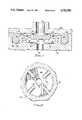
- FIG. 1is a plan view of the top side of the valve of the present invention
- FIG. 2is a cross-sectional view of the valve of FIG. 1 illustrating the configuration of the valve
- FIG. 3is a plan view of the bottom side of the valve shown in FIGS. 1 and 2;
- FIG. 4is a view of the valve shown in FIGS. 1-3 installed between first and second housing portions, with the valve in the closed position;
- FIG. 5is a view of the valve of FIGS. 1-3 installed as shown in FIG. 4 between the first and second housing portions, with the valve in an open position;
- FIG. 6is a schematic block diagram of the operation of a pump using two of the valves of the present invention.
- FIG. 7is a cross-sectional view of an alternate embodiment using valve stop ribs on the floor of the lower housing portion to prevent overtravel by the valve disk rather than using bumps on the bottom side of the valve disk;
- FIG. 8is a cross-sectional view of the top side of the lower housing portion shown in FIG. 7.
- FIG. 6A possible configuration for an infusion pump using two of the valves of the present invention is illustrated schematically in FIG. 6.
- Medication contained in a fluid source 10is to be provided to a patient via a catheter 12, which is of standard design and well known in the art.
- the fluid drivermay be generically described as a pump 14, which may be any of a number of different arrangements, the most common of which is a variable displacement piston and cylinder arrangement.
- the pump 14is driven by a pump driving mechanism 16, which may also be any of a number of different arrangements which are known for controlling an infusion pump.
- Two one-way valves 18A, 18Bare used to control the pumping force generated by the pump 14.
- the first one-way valve 18Ais located in the fluid path between the fluid source 10 and the pump 14, and will only allow fluid to pass from the fluid source 10 to the pump 14.
- the second one-way valve 18Bis located between the pump 14 and the catheter 12, and will only allow fluid to pass from the pump 14 to the catheter 12.
- valves 18A and 18B, and the pump 14would be the disposable components (presumably together with the associated tubing, the catheter, and the empty fluid source).
- the present inventionfocuses on the construction of the valves 18A and 18B, which are usually identical. It will be appreciated by one skilled in the art that the present invention may be adapted to have application in virtually any infusion pump conceivable.
- valve 20which is constructed according to the teachings of the present invention.
- the valve 20consists of three elements, the first of which is a rigid valve disk 22 which includes sealing means and which functions as the actual valve element.
- the second element of the valve 20is a static seal ring 24 which acts both as a seal between upper and lower housing elements (not shown in FIGS. 1 and 2) and as a rigid support structure from which the valve disk 22 may be suspended.
- the third elementis a thin support web 26 extending between the inner diameter of the static seal ring 24 and the outer diamerter of the valve disk 22. The support web is used both to support the valve disk 22 in the proper operating location within housing elements and to bias the valve disk 22 in a closed position which a preselected force in the proper direction may be overcome to open the valve 20.
- the valve 20is quite small, typically having a diameter of approximately 0.20-0.75 inches.
- a valve 20will be described herein which has a diameter of 0.33 inches. It will be recognized by those skilled in the art that the teachings of the present invention are equally applicable to valves of differing sizes for use in such medical devices.
- the valve disk 22is relatively thick to prevent it from exhibiting a significant amount of flexure, particularly under situations when a high pressure in the direction opposite flow would otherwise tend to cause a deflection. It will be appreciated by those skilled in the art that infusion pumps have a relatively small pump displacement, and therefore even a small amount of flexure by the valve disk 22 during pumping would result in both a significant reduction in volumetric efficiency and in an imprecise amount of medication being delivered, making the pump unsuitable for the medical use for which it is intended.
- the valve disk 22has a diameter of 0.12 inches, and a thickness of 0.025 inches.
- top of the valve 20shall be used to mean the side from which fluid originates
- bottom of the valve 20shall mean the side of the valve 20 from which fluid exits as it passes through the valve 20.
- the side shown in the plan view of FIG. 1is the top side of the valve 20, and the side shown in the plan view of FIG. 3 is the bottom side of the valve 20.
- the top sideis shown in FIG. 2 at the top of the figure when viewed in the conventional manner, and the bottom is likewise shown at the bottom of the figure.
- the valve 20has on the bottom side thereof four protruding circular ridges or bumps 28, as shown best in FIG. 3.
- the four bumps 28are mounted around and extend from the periphery of the valve disk 22 on the bottom side of the valve disk 22. They are evenly distributed around the bottom of the valve disk 22, at positions separated by ninety degrees. The purpose of the bumps 28 is to prevent the valve disk 22 from bottoming out and closing off the fluid path, as will be discussed later in this specification.
- the valve disk 22has on the top side of the valve 20 from which fluid originates a dynamic sealing ridge 30, shown best in FIGS. 1 and 2.
- the dynamic sealing ridge 30is cylindrical and extends upwardly from from the outside edge of the valve disk 22.
- the dynamic sealing ridge 30extends 0.01 inches above the surface of the valve disk 22 in the exemplar valve, and has a rounded top surface for enhanced sealing characteristics.
- valve disk 22may be other than circular as shown herein. Additionally, the configurations of the bumps 28 or the sealing ridge 30 may be different, the designs discussed above merely representing the preferred embodiment.
- the static seal ring 24is located concentrically around the valve disk 22, and functions to support and locate the valve disk 22 in position.
- the static seal ringalso functions as a gasket or an O-ring to seal the space between the two housing portions, as will become more evident below in conjunction with the discussion of FIGS. 3 and 4. It is important to note that while the cross-sectional configuration of the static seal ring 24 shown in FIG. 2 is the preferred embodiment, other configurations are possible.
- the static seal ringmust present both a conveniently sealing design and a structurally sound base from which the valve disk 22 is supported.
- the U-shaped cross-section static seal ring 24 shown in FIG. 2accomplishes both objectives admirably.
- the thin support web 26is used to support the valve disk 22 from the static seal ring 24, with the valve disk being capable of movement in essentially one direction only--up and down. Since the entire valve 20 is constructed of elastomeric material, it will be appreciated that the web 26 will tend to bias the valve disk 22 in the position shown in FIG. 2 when no outside forces are applied to the valve 20. In this position the top surface of the static seal ring 24 and the support web 26 are entirely planar, with the dynamic sealing ridge and a portion of the valve disk 22 protruding above this plane.
- the force, and hence the fluid pressure, required to displace the valve disk 22will be highly repeatable. Since the fluid pressure required to supply this force is to be very small, i.e. on the order of 0.1 PSI, it will be appreciated that the support web must be very thin.
- an additional factoris the use in the valve 20 of the present invention of a plurality of apertures 32 through the support web, the apertures 32 being arranged uniformly around the circumference of the valve disk 22.
- the apertures 32there are 10 apertures 32 in the support web 26, each aperture 32 having a diameter of 0.042 inches. Since the outer diameter of the support web 26 where it is connected to the static seal ring 24 is 0.25 inches in the preferred embodiment, the apertures remove a substantial portion of the support web 26, thereby diminishing the force and the fluid pressure necessary to displace the valve disk.
- the practical effect of the apertures 32is that the support web 26 may be made thicker, which in the manufacturing sense makes the valve 20 both easier and more inexpensive to fabricate.
- the apertures 32also serve the purpose of allowing the passage therethrough of fluid entering the valve 20 when the valve disk 22 is open.
- valve 20may be manufactured by molding procedures well known in the art, such as but not limited to injection molding or transfer molding, with the valve 20 illustrated being manufactured in one piece construction.
- the valveis typically molded of a medical grade elastomer such as silicone rubber.
- a critical design criteriais the hardness of the elastomer, which is a compromise between conflicting design considerations.
- the static seal ring 24must have a low stress relaxation characteristic in order to form a good seal after an extended shelf life.
- a durometer hardness of 30-70 on the Shore A scaleencompasses the outer limits on hardness of the material used for the valve 20, with the hardness in the preferred embodiment being between 40 and 50 on the Shore A scale.
- FIG. 4With the construction of the valve 20 being accomplished in sufficient detail, the installation of a valve 20 in the two housing portions is illustrated in FIG. 4.
- the static seal ring 24 of the valve 20is inserted into a circular seal retaining slot 40 in a lower housing portion 42.
- the retaining slot 40is of sufficient depth to accept the portion of the static seal ring 24 in a sealing manner.
- An upper housing portion 44is then lowered into position over the valve 20 and the lower housing portion 44, and secured in position by any of a number of techniques well known in the art, such as by snapping the upper housing portion 44 onto the lower housing portion 42.
- the installation of the upper housing portion 44 onto the lower housing portionwill also compress the static seal ring 24 to form an excellent seal between the upper housing portion 44 and the lower housing portion 42 at the location of the static seal ring 24.
- an optional circular protruding ridge 45which may be formed on the upper housing portion in a manner whereby the circular protruding ridge 45 will be located over a central portion of the top of the static seal ring 24 to ensure an even better seal. It should be noted that with the possible exception of the protruding ridge 45, the side of the upper housing portion 44 facing the valve 20 is flat, thereby accomplishing one of the objects of the present invention.
- an inlet aperture 46Centrally located above the valve disk 22 and within the dynamic sealing ridge 30 is an inlet aperture 46, through which fluid may be admitted to the valve. Since the side of the upper housing portion 44 facing the valve 20 is flat, it will be appreciated that the installation of the upper housing portion 44 over the valve 20 causes the dynamic sealing ridge 30 and the valve disk 22 to be moved downwardly, thereby prestressing the support web 26 and preloading the valve 20 in a closed position.
- the pressure differentialmust reach a threshold value in order to open the valve 20 by forcing the valve disk 22 and the dynamic sealing ridge 30 away from the upper housing portion 44.
- the preloadrequires only a minimal break pressure to open the valve, typically about 0.1 PSI. It is important that the material of the valve 20 have characteristics such that this prestressing of the valve 20 not result in stress relaxation by the material, as discussed above.
- valve 20 on the inlet siderequires and allows only a very small volume of fluid to be stored therein in the cavity formed between the top of the valve disk 22, the interior of the dynamic sealing ridge 30, and the side of the upper housing portion 44 facing the valve 20. This is important to minimize the volume contained within this area on the inlet side of the valve 20 when the valve 20 is used as the valve 18B at the outlet side of the pump 14 shown in FIG. 6.
- a web support 48is integrally fashioned in the lower housing portion radially inside the seal retaining slot 40, with the web support forming the interior side of the seal retaining slot 40. As its name implies, the web support also extends inwardly from the seal retaining slot slightly to support a small portion of the support web 26, in the process slightly increasing the force required to open the valve 20.
- An additional function of the web support 48is to minimize the volume in the chamber outside of the dynamic sealing ridge 30 and between the upper housing portion 44 and the lower housing portion 42, this chamber being on the outlet side of the valve 20.
- a valve chamber floor 50is located beneath the valve disk 22, and an outlet aperture 52 is located in the valve chamber floor 50.
- the web supportmay be larger than depicted in FIG. 4, so long as it does not obstruct the valve disk 22 or the flow of fluid through the apertures 32 and around the valve disk 22.
- the web support 48therefore minimizes the volume contained on the outlet side of the valve 20, which is important when the valve 20 is used as the 18A at the inlet side of the pump 14 shown in FIG. 6.
- the four protruding circular bumps 28, discussed above in conjunction with FIGS. 2 and 3,extend away from the bottom side of the valve disk 22 to prevent the valve disk 22 from blocking the outlet aperture 52 even under the conditions described above.
- the spaces between the bumps 28 and the facing surfaces of the valve disk 22 and the floor 50 of the lower housing portion 42thereby provide a fluid path even when the valve disk 22 is forced downwardly by excessive force.
- valve disk 22rather than having the bumps 28 molded into the bottom of the valve disk 22, apparatus for preventing the valve disk 22 from blocking the outlet aperture 52 under the conditions described above could be located on the floor 50 of the lower housing portion 42.
- the bottom side of the valve disk 22would not have the protruding bumps 28 but rather would be essentially flat with a rounded bottom edge.
- one or more valve stop ribs 54which protrude from the floor 50 of the lower support portion 42 prevent the valve disk 22 from bottoming out and obstructing the outlet aperture 52. The space between the valve stop ribs 54 would thereby provide a fluid path when the valve disk 22 is against the valve stop ribs 54.
- the spring action of the support web 26will maintain the dynamic sealing ridge 30 of the valve disk 26 against the upper housing portion 44 as shown in FIG. 4 when there is no fluid pressure, when the pressure differential across the valve is less than the break pressure, and when the pressure on the outlet side of the valve 20 is greater than the pressure on the inlet side of the valve 20.
- the valve 20will open as shown in FIG. 5, allowing fluid to flow in the inlet aperture 46, around the dynamic sealing ridge 30, through the apertures 32 in the support web 26, and out the outlet aperture 52.
- the support web 26will act to return the valve 20 to a closed position when the pressure across the valve 20 drops below the break pressure.
- the valve 20is highly resistant to reverse flow since the valve disk 22 is relatively thick to prevent substantial deflection therein, thereby maintaining the dynamic sealing ridge 30 tightly against the upper housing portion 44.
- the design of the valve 20 to have a desired break pressureis determined by three factors. First, the thicker the support web, the higher the spring rate and the greater the break pressure of the valve 20. Secondly, the apertures 32 in the support web act to reduce the spring rate and the break pressure of the valve 20 as the number and size of the apertures increase. Finally, the height by which the dynamic sealing ridge 30 projects above the support web 26 provides an offset which determines the preload of the valve disk 22 and the dynamic sealing ridge 30 against the upper housing portion 44.
- the valve 20 of the present inventionis highly precise, and may be economically manufactured. It is suitable for use in medical devices since it is precise, has good shelf and operating lives, and is made of medical grade materials.
- the valve 20has a very small break pressure, yet it seals tightly when this break pressure is not met. It may be used in conjunction with a flat top surface (the upper housing portion 44), thereby making construction of a more economical infusion pump possible and making practical an inexpensive disposable pump with positive valve operation.
- the present inventionthereby represents a valuable and highly desirable improvement in the art, while affording no relative disadvantages.
Landscapes
- Health & Medical Sciences (AREA)
- Engineering & Computer Science (AREA)
- Heart & Thoracic Surgery (AREA)
- Animal Behavior & Ethology (AREA)
- Anesthesiology (AREA)
- Biomedical Technology (AREA)
- Hematology (AREA)
- Life Sciences & Earth Sciences (AREA)
- Pulmonology (AREA)
- General Health & Medical Sciences (AREA)
- Public Health (AREA)
- Veterinary Medicine (AREA)
- General Engineering & Computer Science (AREA)
- Mechanical Engineering (AREA)
- Infusion, Injection, And Reservoir Apparatuses (AREA)
- Check Valves (AREA)
Abstract
Description
Claims (17)
Priority Applications (3)
| Application Number | Priority Date | Filing Date | Title |
|---|---|---|---|
| US06/867,824US4712583A (en) | 1986-05-27 | 1986-05-27 | Precision passive flat-top valve for medication infusion system |
| DE3751314TDE3751314T3 (en) | 1986-05-27 | 1987-05-26 | Valve for a medical infusion system. |
| EP19870304641EP0247824B2 (en) | 1986-05-27 | 1987-05-26 | Valve for medication infusion system |
Applications Claiming Priority (1)
| Application Number | Priority Date | Filing Date | Title |
|---|---|---|---|
| US06/867,824US4712583A (en) | 1986-05-27 | 1986-05-27 | Precision passive flat-top valve for medication infusion system |
Publications (1)
| Publication Number | Publication Date |
|---|---|
| US4712583Atrue US4712583A (en) | 1987-12-15 |
Family
ID=25350527
Family Applications (1)
| Application Number | Title | Priority Date | Filing Date |
|---|---|---|---|
| US06/867,824Expired - LifetimeUS4712583A (en) | 1986-05-27 | 1986-05-27 | Precision passive flat-top valve for medication infusion system |
Country Status (3)
| Country | Link |
|---|---|
| US (1) | US4712583A (en) |
| EP (1) | EP0247824B2 (en) |
| DE (1) | DE3751314T3 (en) |
Cited By (118)
| Publication number | Priority date | Publication date | Assignee | Title |
|---|---|---|---|---|
| US4769012A (en)* | 1984-11-02 | 1988-09-06 | Codan Medizinische Gerate Gmbh & Co. Kg | Gravity infusion and transfusion flow regulating device |
| US4915351A (en)* | 1989-06-30 | 1990-04-10 | Hoffman Albert R | Hose coupling valve |
| US4922947A (en)* | 1987-07-28 | 1990-05-08 | Abx | Automatic membrane drain device for pneumatic circuits |
| US4966185A (en)* | 1988-01-06 | 1990-10-30 | Henk Schram | Inflatable body with a valve and a packaging with such a body |
| US4986310A (en)* | 1990-01-22 | 1991-01-22 | Vernay Laboratories, Inc. | Low pressure check valve |
| US5025829A (en)* | 1990-01-29 | 1991-06-25 | Harmac Medical Products, Inc. | Parenteral check valve |
| US5053013A (en)* | 1990-03-01 | 1991-10-01 | The Regents Of The University Of Michigan | Implantable infusion device |
| US5057084A (en)* | 1990-03-01 | 1991-10-15 | The Regents Of The University Of Michigan | Implantable infusion device |
| US5093047A (en)* | 1990-01-18 | 1992-03-03 | Roediger Pittsburgh, Inc. | Gas diffuser |
| US5103854A (en)* | 1990-01-22 | 1992-04-14 | Vernay Laboratories, Inc. | Low pressure check valve for artificial respiration devices |
| US5176176A (en)* | 1991-11-14 | 1993-01-05 | Graco Inc. | Non-degrading back pressure regulator |
| US5180365A (en)* | 1990-03-01 | 1993-01-19 | Ensminger William D | Implantable infusion device |
| US5215538A (en)* | 1992-02-05 | 1993-06-01 | Abbott Laboratories | Connector-activated in-line valve |
| US5226886A (en)* | 1991-12-06 | 1993-07-13 | Baxter International, Inc. | Ambulatory tubing set with anti-siphon valve |
| US5226879A (en)* | 1990-03-01 | 1993-07-13 | William D. Ensminger | Implantable access device |
| US5263930A (en)* | 1990-03-01 | 1993-11-23 | William D. Ensminger | Implantable access devices |
| US5281199A (en)* | 1990-03-01 | 1994-01-25 | Michigan Transtech Corporation | Implantable access devices |
| US5348179A (en)* | 1992-05-11 | 1994-09-20 | Walker Stainless Equipment Company, Inc. | Venting cap assembly |
| US5350360A (en)* | 1990-03-01 | 1994-09-27 | Michigan Transtech Corporation | Implantable access devices |
| US5352204A (en)* | 1990-03-01 | 1994-10-04 | Ensminger William D | Implantable access devices |
| US5356381A (en)* | 1990-03-01 | 1994-10-18 | Ensminger William D | Implantable access devices |
| GB2295095A (en)* | 1994-11-19 | 1996-05-22 | Smiths Industries Plc | Medical apparatus with valved fluid supply means |
| US5520643A (en)* | 1990-03-01 | 1996-05-28 | Michigan Transtech Corporation | Implantable access devices |
| WO1996024791A1 (en)* | 1995-02-09 | 1996-08-15 | Pradip Choksi | Low actuation pressure unidirectional flow valve |
| US5585011A (en)* | 1993-10-04 | 1996-12-17 | Research International, Inc. | Methods for manufacturing a filter |
| US5617897A (en)* | 1993-02-18 | 1997-04-08 | Schawk, Inc | Nonreturn valve for medical fluid technologies |
| US5697770A (en)* | 1994-12-23 | 1997-12-16 | Robert Bosch Gmbh | Pump using a single diaphragm having preformed oppositely directed bulges forming inlet and outlet valve closing bodies |
| US5728078A (en)* | 1996-03-19 | 1998-03-17 | Powers Dental & Medical Technologies Inc. | Medical suctioning bacteria valve and related method |
| US5848605A (en)* | 1997-11-12 | 1998-12-15 | Cybor Corporation | Check valve |
| EP0934757A2 (en) | 1998-02-08 | 1999-08-11 | 3BY Limited | Check valve |
| US5992462A (en)* | 1998-10-28 | 1999-11-30 | Vernay Laboratories, Inc. | Disc type check valve |
| US6021961A (en)* | 1998-03-06 | 2000-02-08 | Flexible Products Company | Crossover-resistant plural component mixing nozzle |
| US6027097A (en)* | 1998-12-03 | 2000-02-22 | Lakeshore Automatic Products, Inc. | Water stop hose connector |
| US6039302A (en)* | 1996-11-18 | 2000-03-21 | Nypro Inc. | Swabbable luer-activated valve |
| US6106498A (en)* | 1995-07-06 | 2000-08-22 | Disetronic Licensing Ag | Disposable cassette for connection to a liquid drug infusion pump |
| US6148860A (en)* | 1993-09-09 | 2000-11-21 | Sealand Technology, Inc. | Low volume vacuum toilet assembly |
| US6162206A (en)* | 1997-12-23 | 2000-12-19 | Baxter International Inc. | Resealable access site |
| US6290682B1 (en) | 1997-02-13 | 2001-09-18 | Filterek Inc. | Infusion set |
| US6334761B1 (en)* | 2000-03-02 | 2002-01-01 | California Institute Of Technology | Check-valved silicon diaphragm pump and method of fabricating the same |
| US6345649B1 (en)* | 2000-08-10 | 2002-02-12 | Louis Dischler | Bi-stable valve especially useful for pressurizing pen refills |
| US6390120B1 (en)* | 1999-11-12 | 2002-05-21 | Industrie Borla S.P.A. | Check valve for medical infusion lines and the like |
| US6390130B1 (en)* | 1999-11-12 | 2002-05-21 | Industrie Borla Spa | Valve for medical infusion lines and the like |
| WO2002004046A3 (en)* | 2000-07-07 | 2002-06-13 | Fluidsense Corp | Infusion pump cassette |
| US6539987B1 (en) | 2000-08-10 | 2003-04-01 | Louis Dischler | Method of pressure processing enclosures having bi-stable valves |
| US6540262B1 (en) | 2000-01-10 | 2003-04-01 | James W. Humphreys | Ferrule-free hose fittings |
| US20030071235A1 (en)* | 2001-09-25 | 2003-04-17 | Randox Laboratories Limited | Passive microvalve |
| US20030085372A1 (en)* | 2001-10-09 | 2003-05-08 | Newton Brian L. | Medical valve and method of assembling the same |
| US20030089409A1 (en)* | 2001-11-14 | 2003-05-15 | Hirotaka Morimoto | Valve device with check valve, used for washer nozzle and hose joint |
| US20030201012A1 (en)* | 2002-04-30 | 2003-10-30 | Smc Kabushiki Kaisha | Check valve device |
| US20040007601A1 (en)* | 2002-06-26 | 2004-01-15 | Masatoshi Masuda | Valve mechanism for tube-type fluid container |
| US6755391B2 (en) | 2000-10-23 | 2004-06-29 | Nypro Inc. | Anti-drawback medical valve |
| US20040250864A1 (en)* | 2003-06-10 | 2004-12-16 | Zelson Larry Saul | Sanitary check valve |
| US20050016596A1 (en)* | 2002-05-03 | 2005-01-27 | Mijers Jan W. M. | Unidirectional valve appliance |
| US6869426B2 (en) | 2001-11-13 | 2005-03-22 | Nypro Inc. | Anti-drawback medical valve |
| US6883778B1 (en) | 1996-11-18 | 2005-04-26 | Nypro Inc. | Apparatus for reducing fluid drawback through a medical valve |
| US20050179748A1 (en)* | 2002-10-25 | 2005-08-18 | Craig Malik | Techniques for improving pressure sensor shock robustness in fluid containment devices |
| US20050270343A1 (en)* | 2002-10-25 | 2005-12-08 | Malik Craig L | Labyrinth seal structure |
| US20060177330A1 (en)* | 2003-07-23 | 2006-08-10 | Hargraves Technology Corporation | Pump valve with controlled stroke |
| US20070034272A1 (en)* | 2005-07-27 | 2007-02-15 | Aldo Nicolino | Valve assembly |
| USD541935S1 (en) | 2004-07-09 | 2007-05-01 | Filtertek Inc. | Valve for fluids, especially for the medical technique |
| US20070161970A1 (en)* | 2004-04-16 | 2007-07-12 | Medrad, Inc. | Fluid Delivery System, Fluid Path Set, and Pressure Isolation Mechanism with Hemodynamic Pressure Dampening Correction |
| US20070163664A1 (en)* | 2004-06-17 | 2007-07-19 | Mijers Jan W M | Check valve |
| US20070163599A1 (en)* | 2004-06-07 | 2007-07-19 | Mijers Jan W | Apparatus for connecting a respiratory device with a patient |
| US20070251591A1 (en)* | 2004-05-11 | 2007-11-01 | Occupational & Medical Innovations Ltd | One Way Valve That Uses Fluid Pressure to Open and Close the Valve |
| US7357792B2 (en) | 2002-10-29 | 2008-04-15 | Nypro Inc. | Positive push medical valve with internal seal |
| US20080154214A1 (en)* | 2006-12-22 | 2008-06-26 | Medrad, Inc. | Flow Based Pressure Isolation and Fluid Delivery System Including Flow Based Pressure Isolation |
| US20080156381A1 (en)* | 2006-12-27 | 2008-07-03 | Walter Tuymer | Compressor valve |
| US7396348B2 (en) | 2001-08-22 | 2008-07-08 | Nypro Inc. | Medical valve with expandable member |
| US20080172006A1 (en)* | 2007-01-15 | 2008-07-17 | Medrad, Inc. | Patency Check Compatible Check Valve And Fluid Delivery System Including The Patency Check Compatible Check Valve |
| US7516765B2 (en) | 2004-11-22 | 2009-04-14 | Filtertek Inc. | Air vent foil cutter |
| US20090173904A1 (en)* | 2004-10-26 | 2009-07-09 | Roberts James C | Channeled Shaft Check Valve Assemblies |
| US20090173391A1 (en)* | 2008-01-08 | 2009-07-09 | Pradip Choksi | Adjustable pressure relief valve |
| US20090273657A1 (en)* | 2008-05-01 | 2009-11-05 | Xerox Corporation | Rapid Response One-Way Valve for High Speed Solid Ink Delivery |
| US7753892B2 (en) | 2001-11-13 | 2010-07-13 | Nypro Inc. | Anti-drawback medical valve |
| US20100180971A1 (en)* | 2009-01-22 | 2010-07-22 | Liquid Molding Systems, Inc. | Apertured flow control element and housing structure therefor |
| US20100215522A1 (en)* | 2009-02-24 | 2010-08-26 | Murata Manufacturing Co., Ltd. | Check valve, fluid device, and pump |
| US20100217209A1 (en)* | 2009-02-20 | 2010-08-26 | University Of Southern California | Drug delivery device with in-plane bandpass regulation check valve in heat-shrink packaging |
| US20100222769A1 (en)* | 2009-02-20 | 2010-09-02 | University Of Southern California | Mems electrochemical bellows actuator |
| US7789864B2 (en) | 1996-11-18 | 2010-09-07 | Nypro Inc. | Luer-activated valve |
| US7815168B2 (en) | 2006-04-11 | 2010-10-19 | Nypro Inc. | Medical valve with rotating member and method |
| US20100274169A1 (en)* | 2009-04-23 | 2010-10-28 | Fresenius Medical Care Deutschland Gmbh | Valve device, valve insert, external functional means, treatment apparatus, and method |
| US7837658B2 (en) | 2001-11-13 | 2010-11-23 | Nypro Inc. | Anti-drawback medical valve |
| US7887519B2 (en) | 2005-01-14 | 2011-02-15 | Nypro Inc. | Valve with internal lifter |
| US7914502B2 (en) | 2003-07-31 | 2011-03-29 | Nypro Inc. | Anti-drawback medical valve |
| US20110168723A1 (en)* | 2006-10-25 | 2011-07-14 | Radek Malec | Reservoir for a fuel tank |
| US20110308650A1 (en)* | 2009-02-12 | 2011-12-22 | Farid Amirouche | Flow Control System for a Micropump |
| US8100869B2 (en) | 2006-08-11 | 2012-01-24 | Nypro Inc. | Medical valve with expandable member |
| CN102910357A (en)* | 2011-08-02 | 2013-02-06 | 萧兆维 | One-way valve and liquid container |
| US20130146166A1 (en)* | 2011-12-07 | 2013-06-13 | Serge Campeau | Auto shutoff device |
| US20130171537A1 (en)* | 2010-08-20 | 2013-07-04 | Murata Manufacturing Co., Ltd. | Forward check valve and fuel cell system |
| US8568371B2 (en) | 2009-06-22 | 2013-10-29 | Np Medical Inc. | Medical valve with improved back-pressure sealing |
| CN103703292A (en)* | 2011-07-13 | 2014-04-02 | 牛津楠路珀尔科技有限公司 | One-way valve |
| US8771229B2 (en) | 2011-12-01 | 2014-07-08 | Picolife Technologies, Llc | Cartridge system for delivery of medicament |
| US8790307B2 (en) | 2011-12-01 | 2014-07-29 | Picolife Technologies, Llc | Drug delivery device and methods therefor |
| US8925579B2 (en) | 2006-03-02 | 2015-01-06 | Pacific Bag, Inc. | Pressure relief valve |
| US20150159638A1 (en)* | 2012-05-22 | 2015-06-11 | Hitachi Automotive Systems, Ltd. | Pump Device |
| US9138572B2 (en) | 2010-06-24 | 2015-09-22 | Np Medical Inc. | Medical valve with fluid volume alteration |
| CN105190140A (en)* | 2013-03-15 | 2015-12-23 | 西港电力公司 | Check valve with improved response time |
| US9222819B2 (en) | 2009-02-20 | 2015-12-29 | University Of Southern California | Tracking and controlling fluid delivery from chamber |
| US20160144110A1 (en)* | 2013-07-31 | 2016-05-26 | Terumo Kabushiki Kaisha | Connector and transfustion set |
| US9423063B2 (en)* | 2014-11-07 | 2016-08-23 | Plum Industrial Co., Ltd | Oil pipe female coupler |
| KR20170131417A (en)* | 2015-03-25 | 2017-11-29 | 가부시끼가이샤 타쿠미나 | Non-return valve and valve body |
| US20180003309A1 (en)* | 2014-11-11 | 2018-01-04 | Kao Germany Gmbh | Valve, container for receiving and/or mixing fluids, use of a container and method for receiving and/or mixing fluids |
| US9883834B2 (en) | 2012-04-16 | 2018-02-06 | Farid Amirouche | Medication delivery device with multi-reservoir cartridge system and related methods of use |
| US10036065B2 (en) | 2010-10-01 | 2018-07-31 | Oxford Nanopore Technologies Limited | Biochemical analysis apparatus and rotary valve |
| US10094373B2 (en)* | 2011-08-24 | 2018-10-09 | Panasonic Corporation | Valve device of compressor, and sealed compressor including valve device |
| US10130759B2 (en) | 2012-03-09 | 2018-11-20 | Picolife Technologies, Llc | Multi-ported drug delivery device having multi-reservoir cartridge system |
| US10245420B2 (en) | 2012-06-26 | 2019-04-02 | PicoLife Technologies | Medicament distribution systems and related methods of use |
| AU2013398298B2 (en)* | 2013-10-18 | 2019-05-16 | Zammi Instrumental Ltda | Flow-control valve arrangements and improvements |
| US10342589B2 (en) | 2011-09-15 | 2019-07-09 | Oxford Nanopore Technologies Ltd. | Pump |
| US10653879B2 (en) | 2013-03-13 | 2020-05-19 | Carefusion 303, Inc. | Needleless connector with compressible valve |
| US11033726B2 (en)* | 2013-03-14 | 2021-06-15 | Carefusion 303, Inc. | Needleless connector with support member |
| US11187333B1 (en)* | 2020-09-29 | 2021-11-30 | Carefusion 303, Inc. | Color changing and pressure sensing check valves |
| US11428345B2 (en)* | 2017-07-11 | 2022-08-30 | Microfab Service Gmbh | Micro check valve and system with multiple micro check valves and method for the production thereof |
| US11441702B1 (en)* | 2019-05-09 | 2022-09-13 | Facebook Technologies, Llc | Fluidic valve |
| US20230058433A1 (en)* | 2020-01-23 | 2023-02-23 | Mcure Co. Ltd. | Gas and drug sequential injection module for skin treatment, and skin treatment device comprising same |
| US11607489B2 (en) | 2017-05-26 | 2023-03-21 | Bayer Healthcare Llc | Injector state logic with hemodynamic monitoring |
| US11662034B2 (en) | 2019-07-24 | 2023-05-30 | Quest Medical, Inc. | Filtered vacuum relief vent valve |
Families Citing this family (17)
| Publication number | Priority date | Publication date | Assignee | Title |
|---|---|---|---|---|
| FR2721216A1 (en)* | 1994-06-21 | 1995-12-22 | Bruno Chene | Drainage implant for treating hydrocephalus |
| GB2308424B (en)* | 1995-12-19 | 1999-09-29 | Mangar International Ltd | Pressure control valve |
| WO2004004807A1 (en) | 2002-07-09 | 2004-01-15 | Gambro Lundia Ab | An infusion device for medical use. |
| AU2007219646A1 (en)* | 2006-03-02 | 2007-09-07 | Global Valve Technology Limited | Dual seal valve |
| ES2401073T3 (en) | 2006-10-30 | 2013-04-16 | Gambro Lundia Ab | Air separator for extracorporeal fluid treatment sets |
| DE202007011811U1 (en)* | 2007-08-23 | 2007-11-08 | Filtertek B.V., Newcastle West | Check valve, in particular for medical applications |
| WO2009044221A1 (en) | 2007-10-04 | 2009-04-09 | Gambro Lundia Ab | An infusion apparatus |
| EP2307540B1 (en) | 2008-07-07 | 2017-04-19 | Oxford Nanopore Technologies Limited | Enzyme-pore constructs |
| US9205244B2 (en) | 2009-06-29 | 2015-12-08 | Cook Medical Technologies Llc | Haemostatic valve device |
| CN103237572A (en)* | 2010-11-11 | 2013-08-07 | 奇姆德恩医疗有限公司 | Valve used to prevent air from entering the IV circuit |
| CN103648543A (en)* | 2011-05-06 | 2014-03-19 | 赛诺菲-安万特德国有限公司 | Flexible valve geometry for the use of rigid materials |
| KR101682319B1 (en)* | 2012-09-28 | 2016-12-12 | 킴르 하이테크 인코퍼레이티드 | Electronic cigarette and electronic cigarette device thereof |
| GB2510093A (en) | 2012-10-04 | 2014-07-30 | Owen Mumford Ltd | Pen injector with a mechanism for expelling therapeutic material by negative pressure |
| DE102014210231A1 (en) | 2014-05-28 | 2015-12-03 | Robert Bosch Gmbh | Pressure compensation element with a membrane, housing, battery cell module and motor vehicle |
| GB2531991B (en)* | 2014-09-10 | 2020-07-22 | Mayborn Uk Ltd | Valve Assembly |
| EP3342449A1 (en)* | 2017-01-02 | 2018-07-04 | Fresenius Kabi Deutschland GmbH | Port device for injecting a medical fluid into a medical line |
| DE102017121334A1 (en)* | 2017-09-14 | 2019-03-14 | Danfoss Power Solution GmbH & Co OHG | Control disc with increased rigidity and method for producing such a control disc |
Citations (7)
| Publication number | Priority date | Publication date | Assignee | Title |
|---|---|---|---|---|
| US2467189A (en)* | 1947-03-03 | 1949-04-12 | Cohen Milton | Float operated switch |
| US2497906A (en)* | 1944-10-20 | 1950-02-21 | Peters & Russell Inc | Valved hose connection |
| US2758609A (en)* | 1953-05-06 | 1956-08-14 | Henry Flow Control Company | Check valve |
| US3190496A (en)* | 1963-10-14 | 1965-06-22 | Western Metal Specialty Divisi | Valve means for pressurized gas fuel |
| US4143853A (en)* | 1977-07-14 | 1979-03-13 | Metatech Corporation | Valve for use with a catheter or the like |
| US4355639A (en)* | 1980-05-21 | 1982-10-26 | Sis-Ter S.P.A. | Apparatus for the parenteral administration of liquids at a constant, adjustable flow rate |
| US4493339A (en)* | 1982-05-05 | 1985-01-15 | Porter Instrument Company, Inc. | Air valve for a breathing system |
Family Cites Families (3)
| Publication number | Priority date | Publication date | Assignee | Title |
|---|---|---|---|---|
| US2462189A (en)* | 1944-05-25 | 1949-02-22 | Trico Products Corp | Valve for windshield cleaners |
| US4405316A (en)* | 1978-04-03 | 1983-09-20 | Baxter Travenol Laboratories, Inc. | Injection site with check valve inlet |
| EP0031988A1 (en)* | 1980-01-04 | 1981-07-15 | Bruce De Lorenzo | Valve mechanism |
- 1986
- 1986-05-27USUS06/867,824patent/US4712583A/ennot_activeExpired - Lifetime
- 1987
- 1987-05-26EPEP19870304641patent/EP0247824B2/ennot_activeExpired - Lifetime
- 1987-05-26DEDE3751314Tpatent/DE3751314T3/ennot_activeExpired - Lifetime
Patent Citations (7)
| Publication number | Priority date | Publication date | Assignee | Title |
|---|---|---|---|---|
| US2497906A (en)* | 1944-10-20 | 1950-02-21 | Peters & Russell Inc | Valved hose connection |
| US2467189A (en)* | 1947-03-03 | 1949-04-12 | Cohen Milton | Float operated switch |
| US2758609A (en)* | 1953-05-06 | 1956-08-14 | Henry Flow Control Company | Check valve |
| US3190496A (en)* | 1963-10-14 | 1965-06-22 | Western Metal Specialty Divisi | Valve means for pressurized gas fuel |
| US4143853A (en)* | 1977-07-14 | 1979-03-13 | Metatech Corporation | Valve for use with a catheter or the like |
| US4355639A (en)* | 1980-05-21 | 1982-10-26 | Sis-Ter S.P.A. | Apparatus for the parenteral administration of liquids at a constant, adjustable flow rate |
| US4493339A (en)* | 1982-05-05 | 1985-01-15 | Porter Instrument Company, Inc. | Air valve for a breathing system |
Cited By (203)
| Publication number | Priority date | Publication date | Assignee | Title |
|---|---|---|---|---|
| US4769012A (en)* | 1984-11-02 | 1988-09-06 | Codan Medizinische Gerate Gmbh & Co. Kg | Gravity infusion and transfusion flow regulating device |
| US4922947A (en)* | 1987-07-28 | 1990-05-08 | Abx | Automatic membrane drain device for pneumatic circuits |
| US4966185A (en)* | 1988-01-06 | 1990-10-30 | Henk Schram | Inflatable body with a valve and a packaging with such a body |
| US4915351A (en)* | 1989-06-30 | 1990-04-10 | Hoffman Albert R | Hose coupling valve |
| US5093047A (en)* | 1990-01-18 | 1992-03-03 | Roediger Pittsburgh, Inc. | Gas diffuser |
| US4986310A (en)* | 1990-01-22 | 1991-01-22 | Vernay Laboratories, Inc. | Low pressure check valve |
| US5103854A (en)* | 1990-01-22 | 1992-04-14 | Vernay Laboratories, Inc. | Low pressure check valve for artificial respiration devices |
| US5025829A (en)* | 1990-01-29 | 1991-06-25 | Harmac Medical Products, Inc. | Parenteral check valve |
| WO1991011641A1 (en)* | 1990-01-29 | 1991-08-08 | Harmac Medical Products, Inc. | Parenteral check valve |
| US5607393A (en)* | 1990-03-01 | 1997-03-04 | Michigan Transtech Corporation | Implantable access devices |
| US5556381A (en)* | 1990-03-01 | 1996-09-17 | The Michigan Transtech Corporation | Implantable access devices |
| US5792123A (en)* | 1990-03-01 | 1998-08-11 | Michigan Transtech Corporation | Implantable access devices |
| US5180365A (en)* | 1990-03-01 | 1993-01-19 | Ensminger William D | Implantable infusion device |
| US5053013A (en)* | 1990-03-01 | 1991-10-01 | The Regents Of The University Of Michigan | Implantable infusion device |
| US5542923A (en)* | 1990-03-01 | 1996-08-06 | Michigan Transtech Corporation | Implantable access devices |
| US5226879A (en)* | 1990-03-01 | 1993-07-13 | William D. Ensminger | Implantable access device |
| US5263930A (en)* | 1990-03-01 | 1993-11-23 | William D. Ensminger | Implantable access devices |
| US5281199A (en)* | 1990-03-01 | 1994-01-25 | Michigan Transtech Corporation | Implantable access devices |
| US5057084A (en)* | 1990-03-01 | 1991-10-15 | The Regents Of The University Of Michigan | Implantable infusion device |
| US5350360A (en)* | 1990-03-01 | 1994-09-27 | Michigan Transtech Corporation | Implantable access devices |
| US5352204A (en)* | 1990-03-01 | 1994-10-04 | Ensminger William D | Implantable access devices |
| US5356381A (en)* | 1990-03-01 | 1994-10-18 | Ensminger William D | Implantable access devices |
| US5417656A (en)* | 1990-03-01 | 1995-05-23 | Michigan Transtech Corporation | Implantable access devices |
| US5503630A (en)* | 1990-03-01 | 1996-04-02 | Michigan Transtech Corporation | Inplantable access devices |
| US5554117A (en)* | 1990-03-01 | 1996-09-10 | Michigan Transtech Corporation | Implantable access devices |
| US5520643A (en)* | 1990-03-01 | 1996-05-28 | Michigan Transtech Corporation | Implantable access devices |
| US5527277A (en)* | 1990-03-01 | 1996-06-18 | Michigan Transtech Corporation | Implantable access devices |
| US5527278A (en)* | 1990-03-01 | 1996-06-18 | Michigan Transtech Corporation | Implantable access devices |
| US5531684A (en)* | 1990-03-01 | 1996-07-02 | Michigan Transtech Corporation | Implantable access devices |
| US5176176A (en)* | 1991-11-14 | 1993-01-05 | Graco Inc. | Non-degrading back pressure regulator |
| US5226886A (en)* | 1991-12-06 | 1993-07-13 | Baxter International, Inc. | Ambulatory tubing set with anti-siphon valve |
| US5215538A (en)* | 1992-02-05 | 1993-06-01 | Abbott Laboratories | Connector-activated in-line valve |
| US5348179A (en)* | 1992-05-11 | 1994-09-20 | Walker Stainless Equipment Company, Inc. | Venting cap assembly |
| US5617897A (en)* | 1993-02-18 | 1997-04-08 | Schawk, Inc | Nonreturn valve for medical fluid technologies |
| US6148860A (en)* | 1993-09-09 | 2000-11-21 | Sealand Technology, Inc. | Low volume vacuum toilet assembly |
| US5702618A (en)* | 1993-10-04 | 1997-12-30 | Research International, Inc. | Methods for manufacturing a flow switch |
| US5617632A (en)* | 1993-10-04 | 1997-04-08 | Research International, Inc. | Methods for forming a contoured regulator seat |
| US5660728A (en)* | 1993-10-04 | 1997-08-26 | Research International, Inc. | Micromachined fluid handling apparatus with filter |
| US5697153A (en)* | 1993-10-04 | 1997-12-16 | Research International, Inc. | Method for manufacturing a fluid flow regulator |
| US5705070A (en)* | 1993-10-04 | 1998-01-06 | Research International, Inc. | Micromachined filters |
| US5585011A (en)* | 1993-10-04 | 1996-12-17 | Research International, Inc. | Methods for manufacturing a filter |
| US5839467A (en)* | 1993-10-04 | 1998-11-24 | Research International, Inc. | Micromachined fluid handling devices |
| GB2295095A (en)* | 1994-11-19 | 1996-05-22 | Smiths Industries Plc | Medical apparatus with valved fluid supply means |
| GB2295095B (en)* | 1994-11-19 | 1998-07-15 | Smiths Industries Plc | Humidifier system with valved water supply |
| US5697770A (en)* | 1994-12-23 | 1997-12-16 | Robert Bosch Gmbh | Pump using a single diaphragm having preformed oppositely directed bulges forming inlet and outlet valve closing bodies |
| WO1996024791A1 (en)* | 1995-02-09 | 1996-08-15 | Pradip Choksi | Low actuation pressure unidirectional flow valve |
| US5727594A (en)* | 1995-02-09 | 1998-03-17 | Choksi; Pradip | Low actuation pressure unidirectional flow valve |
| US6106498A (en)* | 1995-07-06 | 2000-08-22 | Disetronic Licensing Ag | Disposable cassette for connection to a liquid drug infusion pump |
| US5868701A (en)* | 1996-03-19 | 1999-02-09 | Powers, Jr.; Carleton A. | Medical suctioning bacteria valve and related method |
| US5728078A (en)* | 1996-03-19 | 1998-03-17 | Powers Dental & Medical Technologies Inc. | Medical suctioning bacteria valve and related method |
| US7789864B2 (en) | 1996-11-18 | 2010-09-07 | Nypro Inc. | Luer-activated valve |
| US7100890B2 (en) | 1996-11-18 | 2006-09-05 | Nypro Inc. | Swabbable luer-activated valve |
| US6883778B1 (en) | 1996-11-18 | 2005-04-26 | Nypro Inc. | Apparatus for reducing fluid drawback through a medical valve |
| US6039302A (en)* | 1996-11-18 | 2000-03-21 | Nypro Inc. | Swabbable luer-activated valve |
| US6290682B1 (en) | 1997-02-13 | 2001-09-18 | Filterek Inc. | Infusion set |
| US5848605A (en)* | 1997-11-12 | 1998-12-15 | Cybor Corporation | Check valve |
| US6162206A (en)* | 1997-12-23 | 2000-12-19 | Baxter International Inc. | Resealable access site |
| US6089272A (en)* | 1998-02-08 | 2000-07-18 | 3By Ltd. | Check valve |
| EP0934757A2 (en) | 1998-02-08 | 1999-08-11 | 3BY Limited | Check valve |
| US6021961A (en)* | 1998-03-06 | 2000-02-08 | Flexible Products Company | Crossover-resistant plural component mixing nozzle |
| US5992462A (en)* | 1998-10-28 | 1999-11-30 | Vernay Laboratories, Inc. | Disc type check valve |
| US6027097A (en)* | 1998-12-03 | 2000-02-22 | Lakeshore Automatic Products, Inc. | Water stop hose connector |
| US6390120B1 (en)* | 1999-11-12 | 2002-05-21 | Industrie Borla S.P.A. | Check valve for medical infusion lines and the like |
| US6390130B1 (en)* | 1999-11-12 | 2002-05-21 | Industrie Borla Spa | Valve for medical infusion lines and the like |
| US6540262B1 (en) | 2000-01-10 | 2003-04-01 | James W. Humphreys | Ferrule-free hose fittings |
| US6334761B1 (en)* | 2000-03-02 | 2002-01-01 | California Institute Of Technology | Check-valved silicon diaphragm pump and method of fabricating the same |
| WO2002004046A3 (en)* | 2000-07-07 | 2002-06-13 | Fluidsense Corp | Infusion pump cassette |
| US6345649B1 (en)* | 2000-08-10 | 2002-02-12 | Louis Dischler | Bi-stable valve especially useful for pressurizing pen refills |
| US6539987B1 (en) | 2000-08-10 | 2003-04-01 | Louis Dischler | Method of pressure processing enclosures having bi-stable valves |
| US6755391B2 (en) | 2000-10-23 | 2004-06-29 | Nypro Inc. | Anti-drawback medical valve |
| US7014169B2 (en) | 2000-10-23 | 2006-03-21 | Nypro Inc. | Anti-drawback medical valve |
| US7396348B2 (en) | 2001-08-22 | 2008-07-08 | Nypro Inc. | Medical valve with expandable member |
| US20030071235A1 (en)* | 2001-09-25 | 2003-04-17 | Randox Laboratories Limited | Passive microvalve |
| US20030085372A1 (en)* | 2001-10-09 | 2003-05-08 | Newton Brian L. | Medical valve and method of assembling the same |
| US6892998B2 (en) | 2001-10-09 | 2005-05-17 | Nypro, Inc. | Medical valve and method of assembling the same |
| US9526829B2 (en) | 2001-10-18 | 2016-12-27 | Bayer Healthcare Llc | Flow based pressure isolation and fluid delivery system including flow based pressure isolation and flow initiating mechanism |
| US10137294B2 (en) | 2001-10-18 | 2018-11-27 | Bayer Healthcare Llc | Flow based pressure isolation and fluid delivery system including flow based pressure isolation and flow initiating mechanism |
| US8876784B2 (en) | 2001-11-13 | 2014-11-04 | Np Medical Inc. | Anti-drawback medical valve |
| US7837658B2 (en) | 2001-11-13 | 2010-11-23 | Nypro Inc. | Anti-drawback medical valve |
| US6869426B2 (en) | 2001-11-13 | 2005-03-22 | Nypro Inc. | Anti-drawback medical valve |
| US7753892B2 (en) | 2001-11-13 | 2010-07-13 | Nypro Inc. | Anti-drawback medical valve |
| US20030089409A1 (en)* | 2001-11-14 | 2003-05-15 | Hirotaka Morimoto | Valve device with check valve, used for washer nozzle and hose joint |
| US6948521B2 (en)* | 2002-04-30 | 2005-09-27 | Smc Kabushiki Kaisha | Check valve device |
| US20030201012A1 (en)* | 2002-04-30 | 2003-10-30 | Smc Kabushiki Kaisha | Check valve device |
| US20050016596A1 (en)* | 2002-05-03 | 2005-01-27 | Mijers Jan W. M. | Unidirectional valve appliance |
| US6932110B2 (en) | 2002-05-03 | 2005-08-23 | Filtertek Inc. | Unidirectional valve appliance |
| US20040007601A1 (en)* | 2002-06-26 | 2004-01-15 | Masatoshi Masuda | Valve mechanism for tube-type fluid container |
| US6968976B2 (en)* | 2002-06-26 | 2005-11-29 | Masatoshi Masuda | Valve mechanism for tube-type fluid container |
| US20050179748A1 (en)* | 2002-10-25 | 2005-08-18 | Craig Malik | Techniques for improving pressure sensor shock robustness in fluid containment devices |
| US20050270343A1 (en)* | 2002-10-25 | 2005-12-08 | Malik Craig L | Labyrinth seal structure |
| US7654655B2 (en)* | 2002-10-25 | 2010-02-02 | Hewlett-Packard Development Company, L.P. | Labyrinth seal structure |
| US7465040B2 (en)* | 2002-10-25 | 2008-12-16 | Hewlett-Packard Development Company, L.P. | Labyrinth seal structure with redundant fluid flow paths |
| US7357792B2 (en) | 2002-10-29 | 2008-04-15 | Nypro Inc. | Positive push medical valve with internal seal |
| US8919384B2 (en) | 2002-12-20 | 2014-12-30 | Bayer Medical Care Inc. | Flow based pressure isolation mechanism for a fluid delivery system |
| US7287545B2 (en)* | 2003-06-10 | 2007-10-30 | Larry Saul Zelson | Sanitary check valve |
| US20040250864A1 (en)* | 2003-06-10 | 2004-12-16 | Zelson Larry Saul | Sanitary check valve |
| US7762796B2 (en)* | 2003-07-23 | 2010-07-27 | Hargraves Technology Corporation | Pump valve with controlled stroke |
| US20060177330A1 (en)* | 2003-07-23 | 2006-08-10 | Hargraves Technology Corporation | Pump valve with controlled stroke |
| US9604047B2 (en) | 2003-07-31 | 2017-03-28 | Np Medical Inc. | Anti-drawback medical valve |
| US7914502B2 (en) | 2003-07-31 | 2011-03-29 | Nypro Inc. | Anti-drawback medical valve |
| US20070161970A1 (en)* | 2004-04-16 | 2007-07-12 | Medrad, Inc. | Fluid Delivery System, Fluid Path Set, and Pressure Isolation Mechanism with Hemodynamic Pressure Dampening Correction |
| US7610936B2 (en) | 2004-04-16 | 2009-11-03 | Medrad, Inc. | Flow based pressure isolation mechanism for a fluid delivery system |
| US7975722B2 (en)* | 2004-05-11 | 2011-07-12 | Just Innovative Layouts Pty Ltd | One way valve that uses fluid pressure to open and close the valve |
| US20070251591A1 (en)* | 2004-05-11 | 2007-11-01 | Occupational & Medical Innovations Ltd | One Way Valve That Uses Fluid Pressure to Open and Close the Valve |
| US20070163599A1 (en)* | 2004-06-07 | 2007-07-19 | Mijers Jan W | Apparatus for connecting a respiratory device with a patient |
| US7717116B2 (en) | 2004-06-07 | 2010-05-18 | Filtertek Inc. | Apparatus for connecting a respiratory device with a patient |
| USRE43886E1 (en) | 2004-06-07 | 2013-01-01 | Illinois Tool Works Inc. | Apparatus for connecting a respiratory device with a patient |
| US7673653B2 (en) | 2004-06-17 | 2010-03-09 | Filtertek Inc. | Check valve |
| US20070163664A1 (en)* | 2004-06-17 | 2007-07-19 | Mijers Jan W M | Check valve |
| USD564092S1 (en) | 2004-07-09 | 2008-03-11 | Filtertek Inc. | Valve for fluids, especially for the medical technique |
| USD541935S1 (en) | 2004-07-09 | 2007-05-01 | Filtertek Inc. | Valve for fluids, especially for the medical technique |
| US7971804B2 (en)* | 2004-10-26 | 2011-07-05 | Roberts James C | Channeled shaft check valve assemblies |
| US20090173904A1 (en)* | 2004-10-26 | 2009-07-09 | Roberts James C | Channeled Shaft Check Valve Assemblies |
| US7516765B2 (en) | 2004-11-22 | 2009-04-14 | Filtertek Inc. | Air vent foil cutter |
| US7887519B2 (en) | 2005-01-14 | 2011-02-15 | Nypro Inc. | Valve with internal lifter |
| US20070034272A1 (en)* | 2005-07-27 | 2007-02-15 | Aldo Nicolino | Valve assembly |
| US8925579B2 (en) | 2006-03-02 | 2015-01-06 | Pacific Bag, Inc. | Pressure relief valve |
| US7815168B2 (en) | 2006-04-11 | 2010-10-19 | Nypro Inc. | Medical valve with rotating member and method |
| US8968261B2 (en) | 2006-04-11 | 2015-03-03 | Np Medical Inc. | Medical valve with resilient biasing member |
| US7857284B2 (en) | 2006-04-11 | 2010-12-28 | Nypro Inc. | Medical valve with movable member |
| US7879012B2 (en) | 2006-04-11 | 2011-02-01 | Nypro Inc. | Medical valve with resilient sealing member |
| US8002755B2 (en) | 2006-04-11 | 2011-08-23 | Nypro Inc. | Anti-drawback medical valve and method |
| US8100869B2 (en) | 2006-08-11 | 2012-01-24 | Nypro Inc. | Medical valve with expandable member |
| US8777036B2 (en)* | 2006-10-25 | 2014-07-15 | Robert Bosch Gmbh | Reservoir for a fuel tank |
| US20110168723A1 (en)* | 2006-10-25 | 2011-07-14 | Radek Malec | Reservoir for a fuel tank |
| US20080154214A1 (en)* | 2006-12-22 | 2008-06-26 | Medrad, Inc. | Flow Based Pressure Isolation and Fluid Delivery System Including Flow Based Pressure Isolation |
| US8251092B2 (en) | 2006-12-22 | 2012-08-28 | Medrad, Inc. | Flow based pressure isolation mechanism for a fluid delivery system |
| US7540301B2 (en)* | 2006-12-27 | 2009-06-02 | Walter Tuymer | Compressor valve |
| US20080156381A1 (en)* | 2006-12-27 | 2008-07-03 | Walter Tuymer | Compressor valve |
| US20080172006A1 (en)* | 2007-01-15 | 2008-07-17 | Medrad, Inc. | Patency Check Compatible Check Valve And Fluid Delivery System Including The Patency Check Compatible Check Valve |
| US20090173391A1 (en)* | 2008-01-08 | 2009-07-09 | Pradip Choksi | Adjustable pressure relief valve |
| US7721763B2 (en) | 2008-01-08 | 2010-05-25 | Pradip Choksi | Adjustable pressure relief valve |
| US7883198B2 (en) | 2008-05-01 | 2011-02-08 | Xerox Corporation | Rapid response one-way valve for high speed solid ink delivery |
| US20090273657A1 (en)* | 2008-05-01 | 2009-11-05 | Xerox Corporation | Rapid Response One-Way Valve for High Speed Solid Ink Delivery |
| US8627852B2 (en)* | 2009-01-22 | 2014-01-14 | Aptargroup, Inc. | Apertured flow control element and housing structure therefor |
| US20100180971A1 (en)* | 2009-01-22 | 2010-07-22 | Liquid Molding Systems, Inc. | Apertured flow control element and housing structure therefor |
| US8764425B2 (en) | 2009-02-12 | 2014-07-01 | Picolife Technologies, Llc | Mold for making a membrane for use with a flow control system for a micropump |
| US8663538B2 (en) | 2009-02-12 | 2014-03-04 | Picolife Technologies, Llc | Method of making a membrane for use with a flow control system for a micropump |
| US20110308650A1 (en)* | 2009-02-12 | 2011-12-22 | Farid Amirouche | Flow Control System for a Micropump |
| US8807169B2 (en)* | 2009-02-12 | 2014-08-19 | Picolife Technologies, Llc | Flow control system for a micropump |
| US8579885B2 (en) | 2009-02-20 | 2013-11-12 | University Of Southern California | MEMS electrochemical bellows actuator |
| US9222819B2 (en) | 2009-02-20 | 2015-12-29 | University Of Southern California | Tracking and controlling fluid delivery from chamber |
| US20100217209A1 (en)* | 2009-02-20 | 2010-08-26 | University Of Southern California | Drug delivery device with in-plane bandpass regulation check valve in heat-shrink packaging |
| US20100222769A1 (en)* | 2009-02-20 | 2010-09-02 | University Of Southern California | Mems electrochemical bellows actuator |
| US8372046B2 (en)* | 2009-02-20 | 2013-02-12 | University Of Southern California | Drug delivery device with in-plane bandpass regulation check valve in heat-shrink packaging |
| US20100215522A1 (en)* | 2009-02-24 | 2010-08-26 | Murata Manufacturing Co., Ltd. | Check valve, fluid device, and pump |
| US8205640B2 (en)* | 2009-02-24 | 2012-06-26 | Murata Manufacturing Co., Ltd. | Check valve, fluid device, and pump |
| US9789300B2 (en)* | 2009-04-23 | 2017-10-17 | Fresenius Medical Care Deutschland Gmbh | Valve device, valve insert, external functional means, treatment apparatus, and method |
| US20100274169A1 (en)* | 2009-04-23 | 2010-10-28 | Fresenius Medical Care Deutschland Gmbh | Valve device, valve insert, external functional means, treatment apparatus, and method |
| US8568371B2 (en) | 2009-06-22 | 2013-10-29 | Np Medical Inc. | Medical valve with improved back-pressure sealing |
| US9849274B2 (en) | 2009-06-22 | 2017-12-26 | Np Medical Inc. | Medical valve with improved back-pressure sealing |
| US10744314B2 (en) | 2009-06-22 | 2020-08-18 | Np Medical Inc. | Medical valve with improved back-pressure sealing |
| US9259565B2 (en) | 2009-06-22 | 2016-02-16 | Np Medical Inc. | Medical valve with improved back-pressure sealing |
| US9138572B2 (en) | 2010-06-24 | 2015-09-22 | Np Medical Inc. | Medical valve with fluid volume alteration |
| US9169938B2 (en)* | 2010-08-20 | 2015-10-27 | Murata Manufacturing Co., Ltd. | Forward check valve and fuel cell system |
| US20130171537A1 (en)* | 2010-08-20 | 2013-07-04 | Murata Manufacturing Co., Ltd. | Forward check valve and fuel cell system |
| US10036065B2 (en) | 2010-10-01 | 2018-07-31 | Oxford Nanopore Technologies Limited | Biochemical analysis apparatus and rotary valve |
| US10054234B2 (en) | 2011-07-13 | 2018-08-21 | Oxford Nanopore Technologies Limited | One-way valve |
| CN103703292A (en)* | 2011-07-13 | 2014-04-02 | 牛津楠路珀尔科技有限公司 | One-way valve |
| US9708099B2 (en)* | 2011-08-02 | 2017-07-18 | Sam Siu Wai SIU | Check valve and fluid container comprising the same |
| US20140138342A1 (en)* | 2011-08-02 | 2014-05-22 | Sam Siu Wai SIU | Check valve and fluid container comprising the same |
| CN102910357A (en)* | 2011-08-02 | 2013-02-06 | 萧兆维 | One-way valve and liquid container |
| CN102910357B (en)* | 2011-08-02 | 2016-06-01 | 萧兆维 | Check valve and liquid container |
| US10094373B2 (en)* | 2011-08-24 | 2018-10-09 | Panasonic Corporation | Valve device of compressor, and sealed compressor including valve device |
| US10342589B2 (en) | 2011-09-15 | 2019-07-09 | Oxford Nanopore Technologies Ltd. | Pump |
| US10596322B2 (en) | 2011-09-15 | 2020-03-24 | Oxford Nanopore Technologies Ltd. | Pump |
| US10675412B2 (en) | 2011-09-15 | 2020-06-09 | Oxford Nanopore Technologies Limited | Piston seal |
| US9993592B2 (en) | 2011-12-01 | 2018-06-12 | Picolife Technologies, Llc | Cartridge system for delivery of medicament |
| US8790307B2 (en) | 2011-12-01 | 2014-07-29 | Picolife Technologies, Llc | Drug delivery device and methods therefor |
| US10213549B2 (en) | 2011-12-01 | 2019-02-26 | Picolife Technologies, Llc | Drug delivery device and methods therefor |
| US8771229B2 (en) | 2011-12-01 | 2014-07-08 | Picolife Technologies, Llc | Cartridge system for delivery of medicament |
| US20130146166A1 (en)* | 2011-12-07 | 2013-06-13 | Serge Campeau | Auto shutoff device |
| US10130759B2 (en) | 2012-03-09 | 2018-11-20 | Picolife Technologies, Llc | Multi-ported drug delivery device having multi-reservoir cartridge system |
| US9883834B2 (en) | 2012-04-16 | 2018-02-06 | Farid Amirouche | Medication delivery device with multi-reservoir cartridge system and related methods of use |
| US20150159638A1 (en)* | 2012-05-22 | 2015-06-11 | Hitachi Automotive Systems, Ltd. | Pump Device |
| US10087917B2 (en)* | 2012-05-22 | 2018-10-02 | Hitachi Automotive Systems, Ltd. | Pump device |
| US10245420B2 (en) | 2012-06-26 | 2019-04-02 | PicoLife Technologies | Medicament distribution systems and related methods of use |
| US11602626B2 (en) | 2013-03-13 | 2023-03-14 | Carefusion 303, Inc. | Needleless connector with compressible valve |
| US10653879B2 (en) | 2013-03-13 | 2020-05-19 | Carefusion 303, Inc. | Needleless connector with compressible valve |
| US11730944B2 (en) | 2013-03-14 | 2023-08-22 | Carefusion 303, Inc. | Needleless connector with support member |
| US11033726B2 (en)* | 2013-03-14 | 2021-06-15 | Carefusion 303, Inc. | Needleless connector with support member |
| US10274094B2 (en)* | 2013-03-15 | 2019-04-30 | Westport Power Inc. | Check valve with improved response time |
| CN105190140A (en)* | 2013-03-15 | 2015-12-23 | 西港电力公司 | Check valve with improved response time |
| US20160032920A1 (en)* | 2013-03-15 | 2016-02-04 | Westport Power Inc. | Check valve with improved response time |
| US20160144110A1 (en)* | 2013-07-31 | 2016-05-26 | Terumo Kabushiki Kaisha | Connector and transfustion set |
| US11065383B2 (en)* | 2013-07-31 | 2021-07-20 | Terumo Kabushiki Kaisha | Connector and transfusion set |
| AU2013398298B2 (en)* | 2013-10-18 | 2019-05-16 | Zammi Instrumental Ltda | Flow-control valve arrangements and improvements |
| US9423063B2 (en)* | 2014-11-07 | 2016-08-23 | Plum Industrial Co., Ltd | Oil pipe female coupler |
| US10458558B2 (en)* | 2014-11-11 | 2019-10-29 | Kao Germany Gmbh | Valve, container for receiving and/or mixing fluids, use of a container and method for receiving and/or mixing fluids |
| US20180003309A1 (en)* | 2014-11-11 | 2018-01-04 | Kao Germany Gmbh | Valve, container for receiving and/or mixing fluids, use of a container and method for receiving and/or mixing fluids |
| CN107429853A (en)* | 2015-03-25 | 2017-12-01 | 株式会社泰克米纳 | Check-valves and valve element |
| US10473224B2 (en)* | 2015-03-25 | 2019-11-12 | Tacmina Corporation | Check valve and valve body |
| US20180119833A1 (en)* | 2015-03-25 | 2018-05-03 | Tacmina Corporation | Check Valve and Valve Body |
| KR20170131417A (en)* | 2015-03-25 | 2017-11-29 | 가부시끼가이샤 타쿠미나 | Non-return valve and valve body |
| CN107429853B (en)* | 2015-03-25 | 2019-12-10 | 株式会社泰克米纳 | Check valve and valve core |
| US11607489B2 (en) | 2017-05-26 | 2023-03-21 | Bayer Healthcare Llc | Injector state logic with hemodynamic monitoring |
| US11428345B2 (en)* | 2017-07-11 | 2022-08-30 | Microfab Service Gmbh | Micro check valve and system with multiple micro check valves and method for the production thereof |
| US11441702B1 (en)* | 2019-05-09 | 2022-09-13 | Facebook Technologies, Llc | Fluidic valve |
| US11662034B2 (en) | 2019-07-24 | 2023-05-30 | Quest Medical, Inc. | Filtered vacuum relief vent valve |
| US20230058433A1 (en)* | 2020-01-23 | 2023-02-23 | Mcure Co. Ltd. | Gas and drug sequential injection module for skin treatment, and skin treatment device comprising same |
| US11560960B2 (en) | 2020-09-29 | 2023-01-24 | Carefusion 303, Inc. | Color changing and pressure sensing check valves |
| US11187333B1 (en)* | 2020-09-29 | 2021-11-30 | Carefusion 303, Inc. | Color changing and pressure sensing check valves |
| US11746913B2 (en) | 2020-09-29 | 2023-09-05 | Carefusion 303, Inc. | Color changing and pressure sensing check valves |
Also Published As
| Publication number | Publication date |
|---|---|
| DE3751314T2 (en) | 1996-04-11 |
| EP0247824B2 (en) | 1998-03-04 |
| EP0247824A3 (en) | 1990-11-22 |
| DE3751314D1 (en) | 1995-06-29 |
| EP0247824A2 (en) | 1987-12-02 |
| DE3751314T3 (en) | 1998-08-20 |
| EP0247824B1 (en) | 1995-05-24 |
Similar Documents
| Publication | Publication Date | Title |
|---|---|---|
| US4712583A (en) | Precision passive flat-top valve for medication infusion system | |
| US6089272A (en) | Check valve | |
| US5431634A (en) | Ambulatory pump | |
| EP0288716B1 (en) | Cassette for an infusion system | |
| US5025829A (en) | Parenteral check valve | |
| US5988211A (en) | I.V. flow controller | |
| US4548607A (en) | Implantable manually actuated medication dispensing system | |
| US4354492A (en) | Medical administration set with backflow check valve | |
| CA1176933A (en) | Diaphragm type blood pump for medical use | |
| US4141379A (en) | Check valve | |
| CA1152823A (en) | Implantable drug infusion regulator | |
| US4946448A (en) | Check valve for use with intravenous pump | |
| US4381005A (en) | Intravenous pump chamber | |
| US5433710A (en) | Medication infusion pump with fluoropolymer valve seat | |
| US5305795A (en) | Nonreturn valve, in particular for medical infusion appliances | |
| US4152098A (en) | Micropump | |
| CA1272921A (en) | Parenteral solution diaphragm pump | |
| RU2645362C2 (en) | One way valve | |
| US4898584A (en) | Implantable patient-activated fluid delivery device | |
| US8920386B2 (en) | Micro-valve | |
| RU2279898C2 (en) | Device for introducing liquid medicaments | |
| US5961305A (en) | Pump chamber and valve for a pump chamber | |
| US4827973A (en) | One way flow valve | |
| EP3010578B1 (en) | Bidirectional valve with improved threshold pressure accuracy | |
| JPS59111765A (en) | Injection pump apparatus |
Legal Events
| Date | Code | Title | Description |
|---|---|---|---|
| AS | Assignment | Owner name:PACESETTER INFUSION, LTD., D/B/A MINIMED TECHNOLOG Free format text:ASSIGNMENT OF ASSIGNORS INTEREST.;ASSIGNORS:PELMULDER, JOHN P.;GORTON, LANNY A.;GULESERIAN, ARMEN J.;AND OTHERS;REEL/FRAME:004559/0359 Effective date:19860527 Owner name:PACESETTER INFUSION, LTD., D/B/A MINIMED TECHNOLOG Free format text:ASSIGNMENT OF ASSIGNORS INTEREST;ASSIGNORS:PELMULDER, JOHN P.;GORTON, LANNY A.;GULESERIAN, ARMEN J.;AND OTHERS;REEL/FRAME:004559/0359 Effective date:19860527 | |
| STCF | Information on status: patent grant | Free format text:PATENTED CASE | |
| FEPP | Fee payment procedure | Free format text:PAT HLDR NO LONGER CLAIMS SMALL ENT STAT AS SMALL BUSINESS (ORIGINAL EVENT CODE: LSM2); ENTITY STATUS OF PATENT OWNER: LARGE ENTITY | |
| AS | Assignment | Owner name:SIEMENS CORPORATION, NEW YORK Free format text:SECURITY INTEREST;ASSIGNOR:PACESETTER INFUSION, LTD., D/B/A MINIMED TECHNOLOGIES;REEL/FRAME:005623/0607 Effective date:19910220 | |
| REMI | Maintenance fee reminder mailed | ||
| FPAY | Fee payment | Year of fee payment:4 | |
| SULP | Surcharge for late payment | ||
| FEPP | Fee payment procedure | Free format text:PAYOR NUMBER ASSIGNED (ORIGINAL EVENT CODE: ASPN); ENTITY STATUS OF PATENT OWNER: LARGE ENTITY | |
| AS | Assignment | Owner name:PACESETTER INFUSION, LTD., DBA MINIMED TECHNOLOGIE Free format text:RELEASED BY SECURED PARTY;ASSIGNOR:SIEMENS CORPORATION;REEL/FRAME:006213/0034 Effective date:19920610 | |
| FEPP | Fee payment procedure | Free format text:PAYER NUMBER DE-ASSIGNED (ORIGINAL EVENT CODE: RMPN); ENTITY STATUS OF PATENT OWNER: LARGE ENTITY | |
| AS | Assignment | Owner name:IVAC CORPORATION, CALIFORNIA Free format text:ASSIGNMENT OF ASSIGNORS INTEREST;ASSIGNOR:SIEMENS INFUSION SYSTEMS, LTD.;REEL/FRAME:006893/0197 Effective date:19930922 | |
| AS | Assignment | Owner name:SIEMENS INFUSION SYSTEMS LEGAL DEPARTMENT, CALIF Free format text:CHANGE OF NAME;ASSIGNOR:PACESETTER INFUSION LIMITED;REEL/FRAME:007046/0139 Effective date:19930127 | |
| FPAY | Fee payment | Year of fee payment:8 | |
| FEPP | Fee payment procedure | Free format text:PAYOR NUMBER ASSIGNED (ORIGINAL EVENT CODE: ASPN); ENTITY STATUS OF PATENT OWNER: LARGE ENTITY | |
| AS | Assignment | Owner name:IVAC MEDICAL SYSTEMS, INC., CALIFORNIA Free format text:CHANGE OF NAME;ASSIGNOR:IVAC CORPORATION;REEL/FRAME:007986/0971 Effective date:19960125 | |
| AS | Assignment | Owner name:BANKERS TRUST COMPANY, NEW YORK Free format text:SECURITY INTEREST;ASSIGNOR:IVAC HOLDINGS, INC.;REEL/FRAME:008568/0540 Effective date:19961126 | |
| AS | Assignment | Owner name:ALARIS MEDICAL SYSTEMS, INC., CALIFORNIA Free format text:CHANGE OF NAME;ASSIGNOR:IVAC HOLDINGS, INC.;REEL/FRAME:008621/0107 Effective date:19970429 Owner name:IVAC HOLDINGS, INC., CALIFORNIA Free format text:MERGER;ASSIGNOR:IVAC MEDICAL SYSTEMS, INC.;REEL/FRAME:008621/0113 Effective date:19961126 | |
| FPAY | Fee payment | Year of fee payment:12 | |
| AS | Assignment | Owner name:IISBC BANK USA, NEW YORK Free format text:SECURITY INTEREST;ASSIGNOR:ALARIS MEDICAL SYSTEMS, INC.;REEL/FRAME:013403/0338 Effective date:20011016 | |
| AS | Assignment | Owner name:ALARIS MEDICAL SYSTEMS, INC., CALIFORNIA Free format text:CHANGE OF NAME;ASSIGNOR:ALARIS MEDICAL, INC.;REEL/FRAME:014201/0592 Effective date:20030630 Owner name:ALARIS MEDICAL SYSTEMS, INC., CALIFORNIA Free format text:SECURITY AGREEMENT;ASSIGNOR:HSBC BANK USA;REEL/FRAME:014220/0171 Effective date:20030630 Owner name:ALARIS MEDICAL, INC., CALIFORNIA Free format text:MERGER;ASSIGNOR:ALARIS MEDICAL SYSTEMS, INC.;REEL/FRAME:014220/0417 Effective date:20030630 Owner name:CITICORP NORTH AMERICA, INC., NEW YORK Free format text:SECURITY AGREEMENT;ASSIGNOR:ALARIS MEDICAL SYSTEMS, INC.;REEL/FRAME:014220/0315 Effective date:20030630 | |
| AS | Assignment | Owner name:ALARIS MEDICAL SYSTEMS, INC., CALIFORNIA Free format text:RELEASE OF SECURITY AGREEMENT;ASSIGNOR:CITICORP NORTH AMERICA, INC.;REEL/FRAME:015703/0127 Effective date:20040707 |