US4712160A - Power supply module - Google Patents
Power supply moduleDownload PDFInfo
- Publication number
- US4712160A US4712160AUS06/880,315US88031586AUS4712160AUS 4712160 AUS4712160 AUS 4712160AUS 88031586 AUS88031586 AUS 88031586AUS 4712160 AUS4712160 AUS 4712160A
- Authority
- US
- United States
- Prior art keywords
- primary
- secondary circuit
- circuit boards
- converter transformer
- circuit board
- Prior art date
- Legal status (The legal status is an assumption and is not a legal conclusion. Google has not performed a legal analysis and makes no representation as to the accuracy of the status listed.)
- Expired - Lifetime
Links
Images


Classifications
- H—ELECTRICITY
- H05—ELECTRIC TECHNIQUES NOT OTHERWISE PROVIDED FOR
- H05K—PRINTED CIRCUITS; CASINGS OR CONSTRUCTIONAL DETAILS OF ELECTRIC APPARATUS; MANUFACTURE OF ASSEMBLAGES OF ELECTRICAL COMPONENTS
- H05K1/00—Printed circuits
- H05K1/02—Details
- H05K1/14—Structural association of two or more printed circuits
- H05K1/144—Stacked arrangements of planar printed circuit boards
- H—ELECTRICITY
- H05—ELECTRIC TECHNIQUES NOT OTHERWISE PROVIDED FOR
- H05K—PRINTED CIRCUITS; CASINGS OR CONSTRUCTIONAL DETAILS OF ELECTRIC APPARATUS; MANUFACTURE OF ASSEMBLAGES OF ELECTRICAL COMPONENTS
- H05K5/00—Casings, cabinets or drawers for electric apparatus
- H05K5/0091—Housing specially adapted for small components
Definitions
- the present inventionrelates to a modular construction of a power circuit and converter transformer of a switching power supply unit.
- the integrated module disclosed in Japanese Laid-Open Patent Application No. 44-21621(U.S. Pat. No. 3,359,461) has provided a solution to the conventional problems.
- This modulecomprises power devices and a converter transformer housed in a hollow prism container surrounded by electroconductive side walls.
- the modulehas the following problems:
- the converter transformer in the moduleis susceptible to heat radiation from surrounding power devices.
- a primary circuit board, on one side of which a part of the primary circuit of a switching power supply unit is integrated, and/or a secondary circuit board, on one side of which a part of the secondary circuit of the switching power supply unit is integrated, and a converter transformerare three-dimensionally joined into an integral module using a resin of good thermal conductance and electrical insulation.
- the primary and secondary circuit boardsare arranged so that the device-mounted sides face each other, with the converter transformer placed between them.
- the primary and secondary circuit boardsmay be arranged with the device-mounted sides facing each other and the converter transformer placed in parallel and adjacent to the primary and secondary circuit boards.
- metal substratessuch as aluminum
- FIGS. 1(A), 1(B), 3(A), 3(B), 5(A), 5(B), 7(A), 7(B), 7(C), 8(A), 8(B), 8(C), 10(A), 10(B), 10(C), 12(A), 12(B), 12(C), 13(A), and 13(B)are top and sectional views of embodiments of a power module of the present invention
- FIGS. 4, 6, 9 and 11are top views of embodiments of a power module of the present invention.
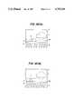
- FIG. 2is a conventional circuit diagram, for reference, of a switching power supply suitable to the power module of the present invention.
- FIGS. 14(A), 14(B), 15(A), 15(B), 16(A), 16(B), 17(A), 17(B), 18(A) and 18(B)are other possible module constructions, modifications of the embodiments of the present invention.
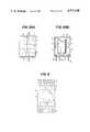
- FIGS. 1(A) and 1(B)show top and sectional views of a power module, a first embodiment of the invention.
- the DC to DC flyback converter circuitis composed of a DC power source (13), a power load (21), a switching transistor (15), a control circuit (14) for controlling ON/OFF operation of the switching transistor (15) to stabilize the voltage output of the power load (21), snubber circuits (16) and (18) added to the switching transistor (15) and a rectifier diode (19), respectively, a converter transformer (3) and a smoothing capacitor (20).
- the operation of the flyback converteris not described here since it is so well known.
- (1)is a primary circuit board on which the components of group A of FIG. 2 are integrated on one side; (2) is a secondary circuit board on which the components of group B of FIG. 2 are integrated on one side; (3) is a converter transformer; (4) is an electrical insulation material for joining the entire module.
- the insulatormay be polyester resin, epoxy resin or other resin which provides high electrical insulation and heat radiation. (Hereinafter, the electrical insulation material is referred to as "resin".)
- Numerals (5) and (6)are devices in component groups A and B, respectively; (7a) is a terminal of circuit board (1) or (2); and (7b) is a terminal of the transformer (3).
- circuit boards (1) and (2)are arranged so that the sides on which devices (5) and (6) are mounted, respectively, face each other, and transformer (3) is placed between circuit boards (1) and (2). Circuit boards (1) and (2) and the transformer (3), thus arranged, are entirely and three-dimensionally joined by the resin (4) into an integral module.
- the power circuitwhose assembly is conventionally discrete, can be assembled into a compact module with the primary and secondary circuits electrically separated.
- FIGS. 3(A) and 3(B)show a second embodiment of the present invention in which radiation from circuit boards (1) and (2) is further improved over the first embodiment.
- FIGS. 3(A) and 3(B)are a top view and a sectional view, respectively, of the second embodiment of the power module of the present invention. Components identical to those in the first embodiment are identified by the same numerals.
- circuit boards (1) and (2) and the converter transformer (3)are entirely and three-dimensionally combined by the resin (4) into an integral module in such a manner that the sides with no devices, i.e., the heat radiating sides of circuit boards (1) and (2), define outer walls of the module.
- the second embodiment with the above constructionprovides the same effects as the first. If metal substrates with good heat radiation properties (such as aluminum substrates) are used for circuit boards (1) and (2), efficiency of heat release through the radiating sides is further improved.
- metal substrates with good heat radiation propertiessuch as aluminum substrates
- Heat sinks (8) mounted on the radiating sides of circuit boards (1) and (2), respectively, as shown in FIG. 4,can increase the heat radiation performance of the power module of the second embodiment.
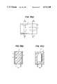
- FIGS. 5(A) and 5(B)are a top view and a sectional view, respectively, of the third embodiment of the power module of the present invention.
- the components identical to those in the second embodimentare designated by the same numerals.
- circuit boards (1) and (2) and the converter transformer (3) of the third embodimentis the same as that, of the second embodiment, except that clearances or empty spaces are provided between the resin (4) and the device-mounted sides of circuit boards (1) and (2), for thermal insulation.
- the clearances (9) between the resin (4) and circuit boards (1) and (2)serve to reduce thermal transmission from circuit boards (1) and (2) to the transformer (3), i.e., prevent heat generated by the devices on circuit boards (1) and (2) from being transmitted to the transformer (3). Simultaneously, the thermal conduction between the two circuit boards is also reduced by the clearances (9). With such thermal insulation, the heat of the entire module can be released outside the module without accumulating inside.
- Heat sinks (8) mounted on circuit boards (1) and (2), as shown in FIG. 6,can further increase the thermal radiation from circuit boards (1) and (2).
- the clearances (9)may be provided between the resin (4) and either of circuit boards (1) and (2) or between the transformer (3) and circuit boards (1) and (2).
- the clearances (9)may be filled with air or resin of good insulation property and low thermal conductance.
- a fourth embodiment, described below,realizes more effective thermal insulation of the transformer (3) from circuit boards (1) and (2).
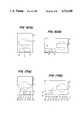
- FIGS. 7(A), 7(B) and 7(C)are top and sectional views, respectively, of the fourth embodiment of the power module of the present invention.
- the components identical to those in the first embodimentare designated by the same numerals.
- circuit boards (1) and (2)are arranged with the device-mounted sides facing each other, and the converter transformer (3) placed in parallel and adjacent to one end of the circuit boards (1) and (2) such that the converter transformer is not between the circuit boards.
- Circuit boards (1) and (2) and the transformer (3) thus arrangedare entirely and three-dimensionally joined by the resin (4) into an integral module.
- the fourth embodiment with the above constructionprovides the same effects as the first embodiment. Compared to the first embodiment, the fourth is superior, in thermal insulation because of the parallel out offset arrangement of the transformer (3) to circuit boards (1) and (2). Accordingly, heat from the transformer (3) is more easily released from the resin (4) in the fourth embodiment than in the first embodiment.
- a fifth embodimentwhich is more advantageous vis-a-vis heat radiation from circuit boards (1) and (2) than the fourth embodiment, will now be described.
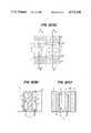
- FIGS. 8(A), 8(B) and 8(C)are top and sectional views, respectively, of the fifth embodiment of the power module of the present invention.
- the components identical to those in the fourth embodimentare designated by the same numerals.
- circuit boards (1) and (2) and the converter transformer (3)are entirely and three-dimensionally joined by the resin (4) into an integral module having the same layout as the fourth embodiment, excepting that the radiating sides of the circuit boards with no device thereon define the outer walls of the module.
- the fifth embodimentadds the advantage of the fourth embodiment to that of the second.
- Heat sinks (8) mounted on circuit boards (1) and (2) of the fifth embodiment, as shown in FIG. 9,further improve the efficiency in heat radiation.
- a sixth embodimentwhich is superior in thermal insulation to the fifth embodiment of the present invention, will now be described.
- FIGS. 10(A), 10(B) and 10(C)are top and sectional views, respectively, of the sixth embodiment of the power module of the present invention.
- the components identical to those in the fifth embodimentare designated by the same numerals.
- circuit boards (1) and (2) and the converter transformer (3) in the sixth embodimentis the same as that in the fifth embodiment, except that clearances (9) are provided between the resin (4) and circuit boards (1) and (2), for thermal insulation.
- the sixth embodimentadds the advantage of the fifth embodiment to that of the third.
- the clearance (9)can be provided between the resin (4) and either of the circuit boards (1) and (2) or between the converter transformer (3) and circuit boards (1) and (2) without losing the effect mentioned above.
- the same effectcan be also expected if the clearance (9) is filled with resin of high insulation and low conductance, in place of air.
- FIGS. 12(A), 12(B) and 12(C)are top sectional views, respectively, of a seventh embodiment of the power module of the present invention.
- the components identical to those in the sixth embodimentare designated by the same numerals.
- the layout of circuit boards (1) and (2) and the converter transformer (3)is the same as the sixth embodiment, except that clearances (10a) are provided between the converter transformer (3) and the heat sinks (8) for the same reason as clearances (9) are provided between circuit boards (1) and (2) and the resin (4) in the fifth embodiment.
- the clearances (10a)serve to reduce thermal transmission from circuit boards (1) and (2) to the converter transformer (3) by hindering transmission of heat from the devices on circuit boards (1) and (2) via the heat sinks (8) to the transformer (3).
- This thermal separation between the heat sinks (8) and the resin (4)allows the heat of the entire module to be released outside the module, without accumulating inside.
- clearances (10a) between the heat sinks (8) and the converter transformer (3)instead of providing the clearances (10a) between the heat sinks (8) and the converter transformer (3), clearances (10b) may be formed in the heat sinks (8) by machining them as shown in FIG. 13. This modification yields the same effect as in the seventh embodiment.
- Embodiments of the present inventionwhich contain either the primary or secondary circuit board will now be described with reference to FIGS. 14 through 18.
- (11)is a primary or secondary circuit board and (12) is a device mounted on the circuit board (11).
- FIGS. 14(A) and 14(B)correspond to those of FIGS. 1 and 4, respectively.
- the embodiments of FIGS. 15(A) and 15(B)correspond to those of FIGS. 2 and 5, respectively.
- the embodiments of FIGS. 16(A), 16(B), 17(A) and 17(B)correspond to those of FIGS. 3 and 6, respectively.
- the embodiments of FIGS. 18(A) and 18(B)correspond to those of FIG. 7.
- the inventionis applied to a flyback switching power supply.
- a power module of the same construction as the above embodimentscan be realized with a switching power supply of another type.
- Circuit boards (1) and (2)may contain control circuits and auxiliary power circuits in addition to the power circuits of the above embodiments.
- the snubber circuitmay be eliminated from the power circuits mounted on the circuit boards.
- circuit boards (1) and (2) and the converter transformer (3)may be three-dimensionally joined by the resin (4) as a unit or, alternatively, circuit boards (1) and (2) and the converter transformer (3) may be independently molded in resin (4) before they are joined.
Landscapes
- Engineering & Computer Science (AREA)
- Microelectronics & Electronic Packaging (AREA)
- Dc-Dc Converters (AREA)
Abstract
Description
1. Field of the Invention
The present invention relates to a modular construction of a power circuit and converter transformer of a switching power supply unit.
2. Description of the Prior Art
In recent years, the development of smaller and lighter low power systems has been progressing remarkably to meet the demand for smaller electronic equipment. As for high power systems, however, particularly power circuits, reduction in size and weight has not yet been realized.
In fact, the mounting technology developed for low power systems is virtually useless for high power systems, due to heat radiation from high power devices and the constructional requirement that high power devices be placed close to one another. Accordingly, in view of the electrical separation between primary and secondary circuits and the heat radiation requirement, a large heat sink is mounted on each semiconductor device of a power system, as a method employed at present.
The integrated module disclosed in Japanese Laid-Open Patent Application No. 44-21621 (U.S. Pat. No. 3,359,461) has provided a solution to the conventional problems. This module comprises power devices and a converter transformer housed in a hollow prism container surrounded by electroconductive side walls. However, the module has the following problems:
(1) It involves many assembly processes because of its complicated structure.
(2) Since the entire module is electroconductive, insulation from surrounding structures is difficult.
(3) The converter transformer in the module is susceptible to heat radiation from surrounding power devices.
(4) Since the power devices are mounted on the side walls, electrical separation between the primary and secondary circuits, essential in power equipment, is difficult.
In short, defective spatial layout of primary and secondary circuits and converter transformers has resulted in the above problems.
It is an object of the present invention to provide a power module which ensures electrical separation between the primary and secondary circuits as well as thermal insulation of the converter transformer from the primary and secondary circuits, and which effectively releases heat.
To achieve the above object, according to the present invention, a primary circuit board, on one side of which a part of the primary circuit of a switching power supply unit is integrated, and/or a secondary circuit board, on one side of which a part of the secondary circuit of the switching power supply unit is integrated, and a converter transformer are three-dimensionally joined into an integral module using a resin of good thermal conductance and electrical insulation.
In the above module of the present invention, the primary and secondary circuit boards are arranged so that the device-mounted sides face each other, with the converter transformer placed between them. Alternatively, the primary and secondary circuit boards may be arranged with the device-mounted sides facing each other and the converter transformer placed in parallel and adjacent to the primary and secondary circuit boards.
Owing to the above construction, it is possible to effectively release heat generated by the power devices on the primary and secondary circuit boards and by the converter transformer, the primary and secondary circuits being electrically separated from each other.
Accordingly, it is possible to realize a small power module which is also simple in assembly.
It is preferable to use metal substrates (such as aluminum) for the primary and secondary circuit boards to achieve better heat radiation.
FIGS. 1(A), 1(B), 3(A), 3(B), 5(A), 5(B), 7(A), 7(B), 7(C), 8(A), 8(B), 8(C), 10(A), 10(B), 10(C), 12(A), 12(B), 12(C), 13(A), and 13(B) are top and sectional views of embodiments of a power module of the present invention;
FIGS. 4, 6, 9 and 11 are top views of embodiments of a power module of the present invention;
FIG. 2 is a conventional circuit diagram, for reference, of a switching power supply suitable to the power module of the present invention; and
FIGS. 14(A), 14(B), 15(A), 15(B), 16(A), 16(B), 17(A), 17(B), 18(A) and 18(B) are other possible module constructions, modifications of the embodiments of the present invention.
Throughout the specification, the following reference numerals will be used in common.
1 . . . Primary circuit board
2 . . . Secondary circuit board
3 . . . Converter transformer
4 . . . Electrical insulation material
5 . . . Power device on the primary side
6 . . . Power device on the secondary side
7a . . . Lead terminal of the circuit board
7b . . . Lead terminal of the converter transformer
8 . . .Heat sink
9, 10a and 10b . . . Clearance
11 . . . Primary or secondary circuit board
12 . . . Power device on the primary or secondary circuit board
13 . . . DC power source
14 . . . Control circuit
15 . . . Switching transistor
16 and 18 . . . Snubber circuit
19 . . . Rectifier diode
20 . . . Smoothing capacitor
21 . . . Load
Some embodiments of a power module of the present invention will be described below, with reference to the accompanying drawings.
FIGS. 1(A) and 1(B) show top and sectional views of a power module, a first embodiment of the invention.
First, a power circuit to which the power module of the present invention is applicable is briefly described with reference to FIG. 2, which shows the well-known circuit of a DC to DC flyback converter. Referring to FIG. 2, the DC to DC flyback converter circuit is composed of a DC power source (13), a power load (21), a switching transistor (15), a control circuit (14) for controlling ON/OFF operation of the switching transistor (15) to stabilize the voltage output of the power load (21), snubber circuits (16) and (18) added to the switching transistor (15) and a rectifier diode (19), respectively, a converter transformer (3) and a smoothing capacitor (20). The operation of the flyback converter is not described here since it is so well known.
In FIG. 2, components which generate heat on the primary circuit are enclosed by dashed line A (group A); those generating heat on the secondary circuit are enclosed by dashed line B (group B). For noise prevention, the wire length between the transformer (3) and component groups A and B should be as short as possible. In addition, it is necessary to electrically separate the circuit of group A from that of group B to ensure insulation.
Referring to FIGS. 1(A) and 1(B): (1) is a primary circuit board on which the components of group A of FIG. 2 are integrated on one side; (2) is a secondary circuit board on which the components of group B of FIG. 2 are integrated on one side; (3) is a converter transformer; (4) is an electrical insulation material for joining the entire module. The insulator may be polyester resin, epoxy resin or other resin which provides high electrical insulation and heat radiation. (Hereinafter, the electrical insulation material is referred to as "resin".) Numerals (5) and (6) are devices in component groups A and B, respectively; (7a) is a terminal of circuit board (1) or (2); and (7b) is a terminal of the transformer (3). In this embodiment, circuit boards (1) and (2) are arranged so that the sides on which devices (5) and (6) are mounted, respectively, face each other, and transformer (3) is placed between circuit boards (1) and (2). Circuit boards (1) and (2) and the transformer (3), thus arranged, are entirely and three-dimensionally joined by the resin (4) into an integral module.
With the above construction, heat generated by circuit boards (1) and (2) and by the transformer (3) is released throughout the resin, so that it is not necessary to provide special radiation measures for each power device. In addition, it is possible to connect the transformer (3) with the circuit boards (1) and (2) by short wire; and since component groups A and B are mounted on separate substrates, the two circuits can be electrically separated.
Thus the power circuit, whose assembly is conventionally discrete, can be assembled into a compact module with the primary and secondary circuits electrically separated.
FIGS. 3(A) and 3(B) show a second embodiment of the present invention in which radiation from circuit boards (1) and (2) is further improved over the first embodiment.
FIGS. 3(A) and 3(B) are a top view and a sectional view, respectively, of the second embodiment of the power module of the present invention. Components identical to those in the first embodiment are identified by the same numerals.
In the second embodiment, circuit boards (1) and (2) and the converter transformer (3) are entirely and three-dimensionally combined by the resin (4) into an integral module in such a manner that the sides with no devices, i.e., the heat radiating sides of circuit boards (1) and (2), define outer walls of the module.
The second embodiment with the above construction provides the same effects as the first. If metal substrates with good heat radiation properties (such as aluminum substrates) are used for circuit boards (1) and (2), efficiency of heat release through the radiating sides is further improved.
Heat sinks (8) mounted on the radiating sides of circuit boards (1) and (2), respectively, as shown in FIG. 4, can increase the heat radiation performance of the power module of the second embodiment.
Now, a third embodiment, superior in thermal insulation to the second embodiment, will be described.
FIGS. 5(A) and 5(B) are a top view and a sectional view, respectively, of the third embodiment of the power module of the present invention. In these figures, the components identical to those in the second embodiment are designated by the same numerals.
The layout of circuit boards (1) and (2) and the converter transformer (3) of the third embodiment is the same as that, of the second embodiment, except that clearances or empty spaces are provided between the resin (4) and the device-mounted sides of circuit boards (1) and (2), for thermal insulation.
The clearances (9) between the resin (4) and circuit boards (1) and (2) serve to reduce thermal transmission from circuit boards (1) and (2) to the transformer (3), i.e., prevent heat generated by the devices on circuit boards (1) and (2) from being transmitted to the transformer (3). Simultaneously, the thermal conduction between the two circuit boards is also reduced by the clearances (9). With such thermal insulation, the heat of the entire module can be released outside the module without accumulating inside.
Heat sinks (8) mounted on circuit boards (1) and (2), as shown in FIG. 6, can further increase the thermal radiation from circuit boards (1) and (2).
The clearances (9) may be provided between the resin (4) and either of circuit boards (1) and (2) or between the transformer (3) and circuit boards (1) and (2).
The clearances (9) may be filled with air or resin of good insulation property and low thermal conductance. A fourth embodiment, described below, realizes more effective thermal insulation of the transformer (3) from circuit boards (1) and (2).
FIGS. 7(A), 7(B) and 7(C) are top and sectional views, respectively, of the fourth embodiment of the power module of the present invention. In the figures, the components identical to those in the first embodiment are designated by the same numerals.
In this embodiment, circuit boards (1) and (2) are arranged with the device-mounted sides facing each other, and the converter transformer (3) placed in parallel and adjacent to one end of the circuit boards (1) and (2) such that the converter transformer is not between the circuit boards. Circuit boards (1) and (2) and the transformer (3) thus arranged are entirely and three-dimensionally joined by the resin (4) into an integral module.
The fourth embodiment with the above construction provides the same effects as the first embodiment. Compared to the first embodiment, the fourth is superior, in thermal insulation because of the parallel out offset arrangement of the transformer (3) to circuit boards (1) and (2). Accordingly, heat from the transformer (3) is more easily released from the resin (4) in the fourth embodiment than in the first embodiment.
A fifth embodiment, which is more advantageous vis-a-vis heat radiation from circuit boards (1) and (2) than the fourth embodiment, will now be described.
FIGS. 8(A), 8(B) and 8(C) are top and sectional views, respectively, of the fifth embodiment of the power module of the present invention. In the figures, the components identical to those in the fourth embodiment are designated by the same numerals.
In this embodiment as well, circuit boards (1) and (2) and the converter transformer (3) are entirely and three-dimensionally joined by the resin (4) into an integral module having the same layout as the fourth embodiment, excepting that the radiating sides of the circuit boards with no device thereon define the outer walls of the module.
The fifth embodiment, with the above construction, adds the advantage of the fourth embodiment to that of the second. Heat sinks (8) mounted on circuit boards (1) and (2) of the fifth embodiment, as shown in FIG. 9, further improve the efficiency in heat radiation.
A sixth embodiment, which is superior in thermal insulation to the fifth embodiment of the present invention, will now be described.
FIGS. 10(A), 10(B) and 10(C) are top and sectional views, respectively, of the sixth embodiment of the power module of the present invention. In the figures, the components identical to those in the fifth embodiment are designated by the same numerals.
The layout of circuit boards (1) and (2) and the converter transformer (3) in the sixth embodiment is the same as that in the fifth embodiment, except that clearances (9) are provided between the resin (4) and circuit boards (1) and (2), for thermal insulation.
The sixth embodiment, with the above construction, adds the advantage of the fifth embodiment to that of the third. Heat sinks (8) mounted on circuit boards (1) and (2) of the sixth embodiment, as shown in FIG. 11, further improve the efficiency in heat radiation from circuit boards (1) and (2).
As in the third embodiment, the clearance (9) can be provided between the resin (4) and either of the circuit boards (1) and (2) or between the converter transformer (3) and circuit boards (1) and (2) without losing the effect mentioned above.
Furthermore, the same effect can be also expected if the clearance (9) is filled with resin of high insulation and low conductance, in place of air.
The most preferable embodiment will be described below, in which the thermal insulation of heat sinks and the converter transformer from the resin is improved beyond that of the sixth embodiment.
FIGS. 12(A), 12(B) and 12(C) are top sectional views, respectively, of a seventh embodiment of the power module of the present invention. The components identical to those in the sixth embodiment are designated by the same numerals.
In this embodiment, the layout of circuit boards (1) and (2) and the converter transformer (3) is the same as the sixth embodiment, except that clearances (10a) are provided between the converter transformer (3) and the heat sinks (8) for the same reason as clearances (9) are provided between circuit boards (1) and (2) and the resin (4) in the fifth embodiment.
The clearances (10a) serve to reduce thermal transmission from circuit boards (1) and (2) to the converter transformer (3) by hindering transmission of heat from the devices on circuit boards (1) and (2) via the heat sinks (8) to the transformer (3). This thermal separation between the heat sinks (8) and the resin (4) allows the heat of the entire module to be released outside the module, without accumulating inside.
As a modified embodiment of the seventh embodiment, instead of providing the clearances (10a) between the heat sinks (8) and the converter transformer (3), clearances (10b) may be formed in the heat sinks (8) by machining them as shown in FIG. 13. This modification yields the same effect as in the seventh embodiment.
All of the above-mentioned, embodiments of the present invention involve both the primary and secondary circuit boards. The same effects as achieved in these embodiments are realized if the module contains either of the primary and secondary circuit boards, as shown in the following embodiments.
Embodiments of the present invention which contain either the primary or secondary circuit board will now be described with reference to FIGS. 14 through 18.
In these figures, (11) is a primary or secondary circuit board and (12) is a device mounted on the circuit board (11).
The embodiments of FIGS. 14(A) and 14(B) correspond to those of FIGS. 1 and 4, respectively. The embodiments of FIGS. 15(A) and 15(B) correspond to those of FIGS. 2 and 5, respectively. The embodiments of FIGS. 16(A), 16(B), 17(A) and 17(B) correspond to those of FIGS. 3 and 6, respectively. And the embodiments of FIGS. 18(A) and 18(B) correspond to those of FIG. 7.
In all of the above embodiments, the invention is applied to a flyback switching power supply. A power module of the same construction as the above embodiments can be realized with a switching power supply of another type.
Only the power circuit parts are mounted on circuit boards (1) and (2) in the above embodiments of the invention. Circuit boards (1) and (2) may contain control circuits and auxiliary power circuits in addition to the power circuits of the above embodiments. Alternatively, the snubber circuit may be eliminated from the power circuits mounted on the circuit boards.
In producing the power module of the present invention, circuit boards (1) and (2) and the converter transformer (3), appropriately arranged, may be three-dimensionally joined by the resin (4) as a unit or, alternatively, circuit boards (1) and (2) and the converter transformer (3) may be independently molded in resin (4) before they are joined.
Claims (8)
1. A power module comprising:
a primary circuit board one major surface of which is an element mounting surface on which circuit elements of a primary circuit of a power circuit are mounted, the other major surface of said primary circuit board being a heat radiating surface on which no circuit element is mounted;
a secondary circuit board one major surface of which is an element mounting surface on which circuit elements of a secondary circuit of said power circuit are mounted, the other major surface of said secondary circuit board being a heat radiating surface on which no circuit element is mounted, said primary and secondary circuit boards being spaced apart from each other and disposed so that the respective element mounting surfaces face each other;
a converter transformer disposed in parallel with and adjacent to said primary and secondary circuit boards; and
a resin body of electrically insulating and thermally conductive resin embedding therein said primary and secondary circuit boards and said converter transformer so that said primary and secondary circuit boards and said converter transformer are three-dimensionally joined only with said resin body, said heat radiating surfaces of said primary and secondary circuit boards being exposed outside to form parts of opposite outer walls of said power module,
wherein a clearance is provided within said resin body along each of said element mounting surfaces of said primary and secondary circuit boards, said clearance being filled with an electrically insulating and thermally low conductive material for preventing heat generated on each of said primary and secondary circuit boards from being transmitted through said resin body to said converter transformer.
2. A power module as claimed in claim 1, further comprising heat sinks provided on said opposite outer walls of said power module for enhancing heat radiation.
3. A power module as claimed in claim 2, wherein an additional clearance is provided within said resin body along a part of each of said heat sinks closer to said converter transformer for preventing heat generated on each of said primary and secondary circuit boards and transmitted to said part of each of said heat sinks from being further transmitted through said resin body to said converter transformer.
4. A power module comprising:
a primary circuit board having a first major surface which is an element mounting surface on which circuit elements of a primary circuit of a power circuit are mounted, said primary circuit board having a second major surface which is a heat radiating surface on which no circuit element is mounted;
a secondary circuit board having a first major surface which is an element mounting surface on which circuit elements of a secondary circuit of said power circuit are mounted, said secondary circuit board having a second major surface which is a heat radiating surface on which no circuit element is mounted, said primary and secondary circuit boards being spaced apart from each other with said first major surface of said primary circuit board facing said first major surface of said secondary circuit board;
a converter transformer disposed between a plane containing said first major surface of said primary circuit board and a plane containing said first major surface of said secondary circuit board;
means joining said primary circuit board, said secondary circuit board and said converter transformer together, said means comprising a resin body of electrically insulating and thermally conductive resin embedding therein said primary and secondary circuit boards with said second major surfaces uncovered by said resin body and said resin body embedding therein said converter transformer so that said primary and secondary circuit boards and said converter transformer are three-dimensionally joined solely by means of said resin body, said heat radiating second major surfaces of said primary and secondary circuit boards being exposed to form parts of opposite outer walls of said power module.
5. The power module of claim 4, wherein a clearance is provided within said resin body along each of said element mounting first major surfaces of said primary and secondary circuit boards, each said clearance being filled with an electrically insulating and thermally low conductive material for preventing heat generated on each of said primary and secondary circuit boards from being transmitted through said resin body to said converter transformer.
6. The power module of claim 4, further comprising heat sinks provided on said opposite outer walls of said power module for enhancing heat radiation.
7. The power module of claim 6, wherein said resin body fills a space between said first major surfaces of said primary and secondary circuit boards and said converter transformer is disposed outside said space with one end of said converter transformer adjacent said space, said resin body including an additional clearance along a part of each of said heat sinks facing said converte transformer for preventing heat generated on each of said primary and secondary circuit boards and transmitted to said part of each of said heat sinks from being further transmitted through said resin body to said converter transformer.
8. The power module of claim 4, wherein said converter transformer is disposed between said first major surfaces of said primary and secondary circuit boards.
Applications Claiming Priority (4)
| Application Number | Priority Date | Filing Date | Title |
|---|---|---|---|
| JP60-145559 | 1985-07-02 | ||
| JP60145559AJPS625696A (en) | 1985-07-02 | 1985-07-02 | power module |
| JP60-150738 | 1985-07-09 | ||
| JP15073885AJPH0632410B2 (en) | 1985-07-09 | 1985-07-09 | Power module |
Publications (1)
| Publication Number | Publication Date |
|---|---|
| US4712160Atrue US4712160A (en) | 1987-12-08 |
Family
ID=26476636
Family Applications (1)
| Application Number | Title | Priority Date | Filing Date |
|---|---|---|---|
| US06/880,315Expired - LifetimeUS4712160A (en) | 1985-07-02 | 1986-06-30 | Power supply module |
Country Status (1)
| Country | Link |
|---|---|
| US (1) | US4712160A (en) |
Cited By (90)
| Publication number | Priority date | Publication date | Assignee | Title |
|---|---|---|---|---|
| US4868732A (en)* | 1987-10-28 | 1989-09-19 | International Business Machines Corporation | Pluggable power system having magnetic flux coupled power transformer and inductive filter components |
| US4899256A (en)* | 1988-06-01 | 1990-02-06 | Chrysler Motors Corporation | Power module |
| US4908734A (en)* | 1986-11-12 | 1990-03-13 | Fanuc Ltd. | Housing for motor control unit |
| US4939491A (en)* | 1988-08-01 | 1990-07-03 | Westinghouse Electric Corp. | Combination barrier and auxiliary CT board |
| US5087932A (en)* | 1989-05-23 | 1992-02-11 | Ricoh Company, Ltd. | Electrophotographic image forming terminal having an improved arrangement of electrical parts |
| AU621907B2 (en)* | 1988-08-01 | 1992-03-26 | Westinghouse Electric Corporation | A circuit breaker having a combination barrier and auxiliary current transformer board |
| US5184281A (en)* | 1992-03-03 | 1993-02-02 | Digital Equipment Corporation | Heat dissipation apparatus |
| US5323295A (en)* | 1992-07-21 | 1994-06-21 | P & P Marketing, Inc. | Assembly for integrating heat generating electronic device with nonheat generating devices |
| US5621635A (en)* | 1995-03-03 | 1997-04-15 | National Semiconductor Corporation | Integrated circuit packaged power supply |
| WO1997034364A1 (en)* | 1995-03-03 | 1997-09-18 | National Semiconductor Corporation | Integrated circuit packaged power supply |
| US5825107A (en)* | 1997-06-13 | 1998-10-20 | General Electric Company | Drive package for a dynamoelectric machine |
| EP0801460A3 (en)* | 1996-04-12 | 1999-04-21 | Lucent Technologies Inc. | Encapsulated, integrated power magnetic device and method of manufacture therefor |
| WO2001020955A1 (en)* | 1999-09-13 | 2001-03-22 | Commergy Technologies Limited | A printed circuit board assembly |
| US6208531B1 (en) | 1993-06-14 | 2001-03-27 | Vlt Corporation | Power converter having magnetically coupled control |
| US20040070946A1 (en)* | 2002-08-21 | 2004-04-15 | Mitsuhiro Matsuo | Power module and production method thereof |
| EP1480500A1 (en)* | 2003-05-16 | 2004-11-24 | Friwo Mobile Power GmbH | Power supply circuit with three dimensionally arranged circuit boards and method of manufacture |
| US6984724B2 (en) | 2001-08-14 | 2006-01-10 | Clariant Gmbh | Pigmented 1-naphtholsulphonic acid-based monoazo pigments |
| US20060076124A1 (en)* | 2004-09-07 | 2006-04-13 | Bahman Sharifipour | Apparatus for and method of cooling molded electronic circuits |
| US7236086B1 (en) | 1993-06-14 | 2007-06-26 | Vlt, Inc. | Power converter configuration, control, and construction |
| US20070159795A1 (en)* | 2006-01-12 | 2007-07-12 | Jui-Kai Tseng | Linear power supply |
| US20070190848A1 (en)* | 2006-02-02 | 2007-08-16 | Xiaoyang Zhang | Power adaptor and storage unit for portable devices |
| US20070263415A1 (en)* | 2006-02-14 | 2007-11-15 | Arian Jansen | Two terminals quasi resonant tank circuit |
| US20080074095A1 (en)* | 2006-09-25 | 2008-03-27 | Telefus Mark D | Bi-directional regulator |
| US20080180909A1 (en)* | 2007-01-30 | 2008-07-31 | Diehl Ako Stiftung & Co. Kg | Mount Module for an Inverter and Inverter Having a Plurality of Mount Modules |
| US20080239760A1 (en)* | 2007-03-29 | 2008-10-02 | Mark Telefus | Primary only constant voltage/constant current (CVCC) control in quasi resonant convertor |
| US20080238379A1 (en)* | 2007-03-29 | 2008-10-02 | Mark Telefus | Pulse frequency to voltage conversion |
| US20080238600A1 (en)* | 2007-03-29 | 2008-10-02 | Olson Bruce D | Method of producing a multi-turn coil from folded flexible circuitry |
| US20080238389A1 (en)* | 2007-03-29 | 2008-10-02 | Mark Telefus | Primary only control quasi resonant convertor |
| US20090079528A1 (en)* | 2007-09-25 | 2009-03-26 | Flextronics Ap, Llc | Thermally enhanced magnetic transformer |
| US20090231810A1 (en)* | 2008-03-11 | 2009-09-17 | Zhenxian Liang | Direct dipping cooled power module and packaging |
| US20090290384A1 (en)* | 2008-05-21 | 2009-11-26 | Flextronics, Ap, Llc | High power factor isolated buck-type power factor correction converter |
| US20090290385A1 (en)* | 2008-05-21 | 2009-11-26 | Flextronics Ap, Llc | Resonant power factor correction converter |
| US20090295531A1 (en)* | 2008-05-28 | 2009-12-03 | Arturo Silva | Optimized litz wire |
| US20090310384A1 (en)* | 2008-06-12 | 2009-12-17 | Bahman Sharifipour | AC-DC input adapter |
| US20100127737A1 (en)* | 2008-11-21 | 2010-05-27 | Flextronics Ap, Llc | Variable PFC and grid-tied bus voltage control |
| US20100142230A1 (en)* | 2007-01-16 | 2010-06-10 | Schroeder Genannt Berghegger Ralf | Simplified primary triggering circuit for the switch in a switched-mode power supply |
| US20100289466A1 (en)* | 2009-05-15 | 2010-11-18 | Flextronics Ap, Llc | Closed loop negative feedback system with low frequency modulated gain |
| US20100315839A1 (en)* | 2009-05-07 | 2010-12-16 | Zaohong Yang | Energy recovery snubber circuit for power converters |
| US20100322441A1 (en)* | 2009-06-23 | 2010-12-23 | Flextronics Ap, Llc | Notebook power supply with integrated subwoofer |
| US20110025286A1 (en)* | 2007-10-17 | 2011-02-03 | Power Systems Technologies Gmbh | Control Circuit For a Primary Controlled Switched Mode Power Supply with Improved Accuracy of the Voltage Control and Primary Controlled Switched Mode Power Supply |
| US7978489B1 (en) | 2007-08-03 | 2011-07-12 | Flextronics Ap, Llc | Integrated power converters |
| US20110170325A1 (en)* | 2010-01-14 | 2011-07-14 | Flextronics Ap, Llc | Line switcher for power converters |
| US20110203840A1 (en)* | 2010-02-23 | 2011-08-25 | Flextronics Ap, Llc | Test point design for a high speed bus |
| WO2012034190A1 (en)* | 2010-09-17 | 2012-03-22 | Intervention Technology Pty Ltd | A power supply device and components thereof |
| US8279646B1 (en) | 2007-12-14 | 2012-10-02 | Flextronics Ap, Llc | Coordinated power sequencing to limit inrush currents and ensure optimum filtering |
| US20130077276A1 (en)* | 2011-09-23 | 2013-03-28 | Astec International Limited | Compact isolated switching power converters |
| US8441810B2 (en) | 2010-11-09 | 2013-05-14 | Flextronics Ap, Llc | Cascade power system architecture |
| US8488340B2 (en) | 2010-08-27 | 2013-07-16 | Flextronics Ap, Llc | Power converter with boost-buck-buck configuration utilizing an intermediate power regulating circuit |
| US8520410B2 (en) | 2010-11-09 | 2013-08-27 | Flextronics Ap, Llc | Virtual parametric high side MOSFET driver |
| US8654553B1 (en) | 2013-03-15 | 2014-02-18 | Flextronics Ap, Llc | Adaptive digital control of power factor correction front end |
| US8743565B2 (en) | 2012-07-27 | 2014-06-03 | Flextronics Ap, Llc | High power converter architecture |
| US8842450B2 (en) | 2011-04-12 | 2014-09-23 | Flextronics, Ap, Llc | Power converter using multiple phase-shifting quasi-resonant converters |
| US8964413B2 (en) | 2010-04-22 | 2015-02-24 | Flextronics Ap, Llc | Two stage resonant converter enabling soft-switching in an isolated stage |
| US9019726B2 (en) | 2012-07-13 | 2015-04-28 | Flextronics Ap, Llc | Power converters with quasi-zero power consumption |
| US9019724B2 (en) | 2012-07-27 | 2015-04-28 | Flextronics Ap, Llc | High power converter architecture |
| US9093911B2 (en) | 2013-03-15 | 2015-07-28 | Flextronics Ap, Llc | Switching mode power converter using coded signal control |
| US9092712B2 (en) | 2012-11-02 | 2015-07-28 | Flextronics Ap, Llc | Embedded high frequency RFID |
| US9118253B2 (en) | 2012-08-15 | 2015-08-25 | Flextronics Ap, Llc | Energy conversion architecture with secondary side control delivered across transformer element |
| US9117991B1 (en) | 2012-02-10 | 2015-08-25 | Flextronics Ap, Llc | Use of flexible circuits incorporating a heat spreading layer and the rigidizing specific areas within such a construction by creating stiffening structures within said circuits by either folding, bending, forming or combinations thereof |
| US9136769B2 (en) | 2012-10-10 | 2015-09-15 | Flextronics Ap, Llc | Load change detection for switched mode power supply with low no load power |
| US9171809B2 (en) | 2013-03-05 | 2015-10-27 | Flextronics Ap, Llc | Escape routes |
| US9182177B2 (en) | 2011-07-12 | 2015-11-10 | Flextronics Ap, Llc | Heat transfer system with integrated evaporator and condenser |
| US9184668B2 (en) | 2013-03-15 | 2015-11-10 | Flextronics Ap, Llc | Power management integrated circuit partitioning with dedicated primary side control winding |
| US9203293B2 (en) | 2012-06-11 | 2015-12-01 | Power Systems Technologies Ltd. | Method of suppressing electromagnetic interference emission |
| US9203292B2 (en) | 2012-06-11 | 2015-12-01 | Power Systems Technologies Ltd. | Electromagnetic interference emission suppressor |
| US9276460B2 (en) | 2012-05-25 | 2016-03-01 | Flextronics Ap, Llc | Power converter with noise immunity |
| US9287792B2 (en) | 2012-08-13 | 2016-03-15 | Flextronics Ap, Llc | Control method to reduce switching loss on MOSFET |
| US9323267B2 (en) | 2013-03-14 | 2016-04-26 | Flextronics Ap, Llc | Method and implementation for eliminating random pulse during power up of digital signal controller |
| US9366394B2 (en) | 2012-06-27 | 2016-06-14 | Flextronics Ap, Llc | Automotive LED headlight cooling system |
| US9397065B1 (en) | 2013-08-27 | 2016-07-19 | Flextronics Ap, Llc | Fixture design for pre-attachment package on package component assembly |
| US9494658B2 (en) | 2013-03-14 | 2016-11-15 | Flextronics Ap, Llc | Approach for generation of power failure warning signal to maximize useable hold-up time with AC/DC rectifiers |
| US9521754B1 (en) | 2013-08-19 | 2016-12-13 | Multek Technologies Limited | Embedded components in a substrate |
| US9549463B1 (en) | 2014-05-16 | 2017-01-17 | Multek Technologies, Ltd. | Rigid to flexible PC transition |
| US9565748B2 (en) | 2013-10-28 | 2017-02-07 | Flextronics Ap, Llc | Nano-copper solder for filling thermal vias |
| US9605860B2 (en) | 2012-11-02 | 2017-03-28 | Flextronics Ap, Llc | Energy saving-exhaust control and auto shut off system |
| US9621053B1 (en) | 2014-08-05 | 2017-04-11 | Flextronics Ap, Llc | Peak power control technique for primary side controller operation in continuous conduction mode |
| US9661738B1 (en) | 2014-09-03 | 2017-05-23 | Flextronics Ap, Llc | Embedded coins for HDI or SEQ laminations |
| US9660540B2 (en) | 2012-11-05 | 2017-05-23 | Flextronics Ap, Llc | Digital error signal comparator |
| US9661743B1 (en) | 2013-12-09 | 2017-05-23 | Multek Technologies, Ltd. | Flexible circuit board and method of fabricating |
| US9668336B1 (en) | 2012-05-18 | 2017-05-30 | Flextronics Ap, Llc | Inlay PCB with embedded coin board |
| US9711990B2 (en) | 2013-03-15 | 2017-07-18 | Flextronics Ap, Llc | No load detection and slew rate compensation |
| US9723713B1 (en) | 2014-05-16 | 2017-08-01 | Multek Technologies, Ltd. | Flexible printed circuit board hinge |
| GB2547087A (en)* | 2015-12-17 | 2017-08-09 | Bosch Gmbh Robert | Converter circuit |
| US9862561B2 (en) | 2012-12-03 | 2018-01-09 | Flextronics Ap, Llc | Driving board folding machine and method of using a driving board folding machine to fold a flexible circuit |
| US10064292B2 (en) | 2016-03-21 | 2018-08-28 | Multek Technologies Limited | Recessed cavity in printed circuit board protected by LPI |
| US10123603B1 (en) | 2015-03-27 | 2018-11-13 | Multek Technologies Limited | Diffuse fiber optic lighting for luggage |
| US10154583B1 (en) | 2015-03-27 | 2018-12-11 | Flex Ltd | Mechanical strain reduction on flexible and rigid-flexible circuits |
| US10321560B2 (en) | 2015-11-12 | 2019-06-11 | Multek Technologies Limited | Dummy core plus plating resist restrict resin process and structure |
| US10645807B1 (en) | 2013-08-27 | 2020-05-05 | Flextronics Ap, Llc. | Component attach on metal woven mesh |
| US10712398B1 (en) | 2016-06-21 | 2020-07-14 | Multek Technologies Limited | Measuring complex PCB-based interconnects in a production environment |
Citations (5)
| Publication number | Priority date | Publication date | Assignee | Title |
|---|---|---|---|---|
| US3359461A (en)* | 1967-02-15 | 1967-12-19 | Powercube Corp | Modular circuit package |
| US3582714A (en)* | 1969-07-24 | 1971-06-01 | Lambda Electronics Corp | Multiple-output chassis-less power supply having a heat dissipating housing of unitary construction |
| US3699394A (en)* | 1971-11-01 | 1972-10-17 | Powercube Corp | Modular circuit package with enhanced heat dissipation |
| US3934177A (en)* | 1975-01-09 | 1976-01-20 | Stephen Horbach | Heat sink casing for circuit board components |
| US4218724A (en)* | 1978-11-21 | 1980-08-19 | Kaufman Lance R | Compact circuit package having improved circuit connectors |
- 1986
- 1986-06-30USUS06/880,315patent/US4712160A/ennot_activeExpired - Lifetime
Patent Citations (5)
| Publication number | Priority date | Publication date | Assignee | Title |
|---|---|---|---|---|
| US3359461A (en)* | 1967-02-15 | 1967-12-19 | Powercube Corp | Modular circuit package |
| US3582714A (en)* | 1969-07-24 | 1971-06-01 | Lambda Electronics Corp | Multiple-output chassis-less power supply having a heat dissipating housing of unitary construction |
| US3699394A (en)* | 1971-11-01 | 1972-10-17 | Powercube Corp | Modular circuit package with enhanced heat dissipation |
| US3934177A (en)* | 1975-01-09 | 1976-01-20 | Stephen Horbach | Heat sink casing for circuit board components |
| US4218724A (en)* | 1978-11-21 | 1980-08-19 | Kaufman Lance R | Compact circuit package having improved circuit connectors |
Cited By (130)
| Publication number | Priority date | Publication date | Assignee | Title |
|---|---|---|---|---|
| US4908734A (en)* | 1986-11-12 | 1990-03-13 | Fanuc Ltd. | Housing for motor control unit |
| US4868732A (en)* | 1987-10-28 | 1989-09-19 | International Business Machines Corporation | Pluggable power system having magnetic flux coupled power transformer and inductive filter components |
| US4899256A (en)* | 1988-06-01 | 1990-02-06 | Chrysler Motors Corporation | Power module |
| US4939491A (en)* | 1988-08-01 | 1990-07-03 | Westinghouse Electric Corp. | Combination barrier and auxiliary CT board |
| AU621907B2 (en)* | 1988-08-01 | 1992-03-26 | Westinghouse Electric Corporation | A circuit breaker having a combination barrier and auxiliary current transformer board |
| US5087932A (en)* | 1989-05-23 | 1992-02-11 | Ricoh Company, Ltd. | Electrophotographic image forming terminal having an improved arrangement of electrical parts |
| US5184281A (en)* | 1992-03-03 | 1993-02-02 | Digital Equipment Corporation | Heat dissipation apparatus |
| US5323295A (en)* | 1992-07-21 | 1994-06-21 | P & P Marketing, Inc. | Assembly for integrating heat generating electronic device with nonheat generating devices |
| US6208531B1 (en) | 1993-06-14 | 2001-03-27 | Vlt Corporation | Power converter having magnetically coupled control |
| US7236086B1 (en) | 1993-06-14 | 2007-06-26 | Vlt, Inc. | Power converter configuration, control, and construction |
| US5621635A (en)* | 1995-03-03 | 1997-04-15 | National Semiconductor Corporation | Integrated circuit packaged power supply |
| WO1997034364A1 (en)* | 1995-03-03 | 1997-09-18 | National Semiconductor Corporation | Integrated circuit packaged power supply |
| EP0801460A3 (en)* | 1996-04-12 | 1999-04-21 | Lucent Technologies Inc. | Encapsulated, integrated power magnetic device and method of manufacture therefor |
| US5825107A (en)* | 1997-06-13 | 1998-10-20 | General Electric Company | Drive package for a dynamoelectric machine |
| WO2001020955A1 (en)* | 1999-09-13 | 2001-03-22 | Commergy Technologies Limited | A printed circuit board assembly |
| US6982876B1 (en) | 1999-09-13 | 2006-01-03 | Commergy Technologies Limited | Printed circuit board assembly |
| US6984724B2 (en) | 2001-08-14 | 2006-01-10 | Clariant Gmbh | Pigmented 1-naphtholsulphonic acid-based monoazo pigments |
| US7057896B2 (en)* | 2002-08-21 | 2006-06-06 | Matsushita Electric Industrial Co., Ltd. | Power module and production method thereof |
| US20040070946A1 (en)* | 2002-08-21 | 2004-04-15 | Mitsuhiro Matsuo | Power module and production method thereof |
| US7688597B2 (en)* | 2003-05-16 | 2010-03-30 | Power Systems Technologies Gmbh | Power supply circuit with three-dimensionally arranged circuit carriers, and production method |
| EP1480500A1 (en)* | 2003-05-16 | 2004-11-24 | Friwo Mobile Power GmbH | Power supply circuit with three dimensionally arranged circuit boards and method of manufacture |
| US20050047103A1 (en)* | 2003-05-16 | 2005-03-03 | Friwo Mobile Power Gmbh | Power supply circuit with three-dimensionally arranged circuit carriers, and production method |
| US20110103119A1 (en)* | 2004-09-07 | 2011-05-05 | Flextronics Ap, Llc | Apparatus for and method of cooling electronic circuits |
| US20060076124A1 (en)* | 2004-09-07 | 2006-04-13 | Bahman Sharifipour | Apparatus for and method of cooling molded electronic circuits |
| US8295048B2 (en) | 2004-09-07 | 2012-10-23 | Flextronics Ap, Llc | Apparatus for and method of cooling electronic circuits |
| US7885076B2 (en)* | 2004-09-07 | 2011-02-08 | Flextronics Ap, Llc | Apparatus for and method of cooling molded electronic circuits |
| US20070159795A1 (en)* | 2006-01-12 | 2007-07-12 | Jui-Kai Tseng | Linear power supply |
| US20070190848A1 (en)* | 2006-02-02 | 2007-08-16 | Xiaoyang Zhang | Power adaptor and storage unit for portable devices |
| US7989981B2 (en) | 2006-02-02 | 2011-08-02 | Flextronics Ap, Llc | Power adaptor and storage unit for portable devices |
| US20100061123A1 (en)* | 2006-02-14 | 2010-03-11 | Flextronics Ap, Llc | Two terminals quasi resonant tank circuit |
| US7924577B2 (en) | 2006-02-14 | 2011-04-12 | Flextronics Ap, Llc | Two terminals quasi resonant tank circuit |
| US20100067276A1 (en)* | 2006-02-14 | 2010-03-18 | Flextronics Ap, Llc | Two terminals quasi resonant tank circuit |
| US7924578B2 (en) | 2006-02-14 | 2011-04-12 | Flextronics Ap, Llc | Two terminals quasi resonant tank circuit |
| US7764515B2 (en) | 2006-02-14 | 2010-07-27 | Flextronics Ap, Llc | Two terminals quasi resonant tank circuit |
| US20070263415A1 (en)* | 2006-02-14 | 2007-11-15 | Arian Jansen | Two terminals quasi resonant tank circuit |
| US8223522B2 (en) | 2006-09-25 | 2012-07-17 | Flextronics Ap, Llc | Bi-directional regulator for regulating power |
| US20080074095A1 (en)* | 2006-09-25 | 2008-03-27 | Telefus Mark D | Bi-directional regulator |
| US8467201B2 (en) | 2007-01-16 | 2013-06-18 | Flextronics GmbH & Co KG | Simplified primary triggering circuit for the switch in a switched-mode power supply |
| US20100142230A1 (en)* | 2007-01-16 | 2010-06-10 | Schroeder Genannt Berghegger Ralf | Simplified primary triggering circuit for the switch in a switched-mode power supply |
| US7667963B2 (en)* | 2007-01-30 | 2010-02-23 | Diehl Ako Stiftung & Co. Kg | Mount module for an inverter and inverter having a plurality of mount modules |
| US20080180909A1 (en)* | 2007-01-30 | 2008-07-31 | Diehl Ako Stiftung & Co. Kg | Mount Module for an Inverter and Inverter Having a Plurality of Mount Modules |
| US20080238379A1 (en)* | 2007-03-29 | 2008-10-02 | Mark Telefus | Pulse frequency to voltage conversion |
| US7755914B2 (en) | 2007-03-29 | 2010-07-13 | Flextronics Ap, Llc | Pulse frequency to voltage conversion |
| US7760519B2 (en) | 2007-03-29 | 2010-07-20 | Flextronics Ap, Llc | Primary only control quasi resonant convertor |
| US20080239760A1 (en)* | 2007-03-29 | 2008-10-02 | Mark Telefus | Primary only constant voltage/constant current (CVCC) control in quasi resonant convertor |
| US7830676B2 (en) | 2007-03-29 | 2010-11-09 | Flextronics Ap, Llc | Primary only constant voltage/constant current (CVCC) control in quasi resonant convertor |
| US8191241B2 (en) | 2007-03-29 | 2012-06-05 | Flextronics Ap, Llc | Method of producing a multi-turn coil from folded flexible circuitry |
| US8387234B2 (en) | 2007-03-29 | 2013-03-05 | Flextronics Ap, Llc | Multi-turn coil device |
| US20080238600A1 (en)* | 2007-03-29 | 2008-10-02 | Olson Bruce D | Method of producing a multi-turn coil from folded flexible circuitry |
| US20080238389A1 (en)* | 2007-03-29 | 2008-10-02 | Mark Telefus | Primary only control quasi resonant convertor |
| US20110050381A1 (en)* | 2007-03-29 | 2011-03-03 | Flextronics Ap, Llc | Method of producing a multi-turn coil from folded flexible circuitry |
| US7978489B1 (en) | 2007-08-03 | 2011-07-12 | Flextronics Ap, Llc | Integrated power converters |
| US7920039B2 (en) | 2007-09-25 | 2011-04-05 | Flextronics Ap, Llc | Thermally enhanced magnetic transformer |
| US20090079528A1 (en)* | 2007-09-25 | 2009-03-26 | Flextronics Ap, Llc | Thermally enhanced magnetic transformer |
| US8582323B2 (en) | 2007-10-17 | 2013-11-12 | Flextronics Ap, Llc | Control circuit for a primary controlled switched mode power supply with improved accuracy of the voltage control and primary controlled switched mode power supply |
| US20110025286A1 (en)* | 2007-10-17 | 2011-02-03 | Power Systems Technologies Gmbh | Control Circuit For a Primary Controlled Switched Mode Power Supply with Improved Accuracy of the Voltage Control and Primary Controlled Switched Mode Power Supply |
| US8279646B1 (en) | 2007-12-14 | 2012-10-02 | Flextronics Ap, Llc | Coordinated power sequencing to limit inrush currents and ensure optimum filtering |
| US20090231810A1 (en)* | 2008-03-11 | 2009-09-17 | Zhenxian Liang | Direct dipping cooled power module and packaging |
| US7911792B2 (en)* | 2008-03-11 | 2011-03-22 | Ford Global Technologies Llc | Direct dipping cooled power module and packaging |
| US8693213B2 (en) | 2008-05-21 | 2014-04-08 | Flextronics Ap, Llc | Resonant power factor correction converter |
| US8102678B2 (en) | 2008-05-21 | 2012-01-24 | Flextronics Ap, Llc | High power factor isolated buck-type power factor correction converter |
| US20090290385A1 (en)* | 2008-05-21 | 2009-11-26 | Flextronics Ap, Llc | Resonant power factor correction converter |
| US20090290384A1 (en)* | 2008-05-21 | 2009-11-26 | Flextronics, Ap, Llc | High power factor isolated buck-type power factor correction converter |
| US8975523B2 (en) | 2008-05-28 | 2015-03-10 | Flextronics Ap, Llc | Optimized litz wire |
| US20090295531A1 (en)* | 2008-05-28 | 2009-12-03 | Arturo Silva | Optimized litz wire |
| US8531174B2 (en) | 2008-06-12 | 2013-09-10 | Flextronics Ap, Llc | AC-DC input adapter |
| US20090310384A1 (en)* | 2008-06-12 | 2009-12-17 | Bahman Sharifipour | AC-DC input adapter |
| US8081019B2 (en) | 2008-11-21 | 2011-12-20 | Flextronics Ap, Llc | Variable PFC and grid-tied bus voltage control |
| US20100127737A1 (en)* | 2008-11-21 | 2010-05-27 | Flextronics Ap, Llc | Variable PFC and grid-tied bus voltage control |
| US8787044B2 (en) | 2009-05-07 | 2014-07-22 | Flextronics Ap, Llc | Energy recovery snubber circuit for power converters |
| US20100315839A1 (en)* | 2009-05-07 | 2010-12-16 | Zaohong Yang | Energy recovery snubber circuit for power converters |
| US20100289466A1 (en)* | 2009-05-15 | 2010-11-18 | Flextronics Ap, Llc | Closed loop negative feedback system with low frequency modulated gain |
| US8040117B2 (en) | 2009-05-15 | 2011-10-18 | Flextronics Ap, Llc | Closed loop negative feedback system with low frequency modulated gain |
| US8891803B2 (en) | 2009-06-23 | 2014-11-18 | Flextronics Ap, Llc | Notebook power supply with integrated subwoofer |
| US20100322441A1 (en)* | 2009-06-23 | 2010-12-23 | Flextronics Ap, Llc | Notebook power supply with integrated subwoofer |
| US8289741B2 (en) | 2010-01-14 | 2012-10-16 | Flextronics Ap, Llc | Line switcher for power converters |
| US20110170325A1 (en)* | 2010-01-14 | 2011-07-14 | Flextronics Ap, Llc | Line switcher for power converters |
| US20110203840A1 (en)* | 2010-02-23 | 2011-08-25 | Flextronics Ap, Llc | Test point design for a high speed bus |
| US8586873B2 (en) | 2010-02-23 | 2013-11-19 | Flextronics Ap, Llc | Test point design for a high speed bus |
| US8964413B2 (en) | 2010-04-22 | 2015-02-24 | Flextronics Ap, Llc | Two stage resonant converter enabling soft-switching in an isolated stage |
| US8488340B2 (en) | 2010-08-27 | 2013-07-16 | Flextronics Ap, Llc | Power converter with boost-buck-buck configuration utilizing an intermediate power regulating circuit |
| WO2012034190A1 (en)* | 2010-09-17 | 2012-03-22 | Intervention Technology Pty Ltd | A power supply device and components thereof |
| US8520410B2 (en) | 2010-11-09 | 2013-08-27 | Flextronics Ap, Llc | Virtual parametric high side MOSFET driver |
| US8441810B2 (en) | 2010-11-09 | 2013-05-14 | Flextronics Ap, Llc | Cascade power system architecture |
| US8842450B2 (en) | 2011-04-12 | 2014-09-23 | Flextronics, Ap, Llc | Power converter using multiple phase-shifting quasi-resonant converters |
| US9182177B2 (en) | 2011-07-12 | 2015-11-10 | Flextronics Ap, Llc | Heat transfer system with integrated evaporator and condenser |
| US8897029B2 (en)* | 2011-09-23 | 2014-11-25 | Astec International Limited | Compact isolated switching power converters |
| US20130077276A1 (en)* | 2011-09-23 | 2013-03-28 | Astec International Limited | Compact isolated switching power converters |
| US9117991B1 (en) | 2012-02-10 | 2015-08-25 | Flextronics Ap, Llc | Use of flexible circuits incorporating a heat spreading layer and the rigidizing specific areas within such a construction by creating stiffening structures within said circuits by either folding, bending, forming or combinations thereof |
| US9668336B1 (en) | 2012-05-18 | 2017-05-30 | Flextronics Ap, Llc | Inlay PCB with embedded coin board |
| US9276460B2 (en) | 2012-05-25 | 2016-03-01 | Flextronics Ap, Llc | Power converter with noise immunity |
| US9203293B2 (en) | 2012-06-11 | 2015-12-01 | Power Systems Technologies Ltd. | Method of suppressing electromagnetic interference emission |
| US9203292B2 (en) | 2012-06-11 | 2015-12-01 | Power Systems Technologies Ltd. | Electromagnetic interference emission suppressor |
| US9366394B2 (en) | 2012-06-27 | 2016-06-14 | Flextronics Ap, Llc | Automotive LED headlight cooling system |
| US9019726B2 (en) | 2012-07-13 | 2015-04-28 | Flextronics Ap, Llc | Power converters with quasi-zero power consumption |
| US9019724B2 (en) | 2012-07-27 | 2015-04-28 | Flextronics Ap, Llc | High power converter architecture |
| US8743565B2 (en) | 2012-07-27 | 2014-06-03 | Flextronics Ap, Llc | High power converter architecture |
| US9287792B2 (en) | 2012-08-13 | 2016-03-15 | Flextronics Ap, Llc | Control method to reduce switching loss on MOSFET |
| US9118253B2 (en) | 2012-08-15 | 2015-08-25 | Flextronics Ap, Llc | Energy conversion architecture with secondary side control delivered across transformer element |
| US9312775B2 (en) | 2012-08-15 | 2016-04-12 | Flextronics Ap, Llc | Reconstruction pulse shape integrity in feedback control environment |
| US9318965B2 (en) | 2012-10-10 | 2016-04-19 | Flextronics Ap, Llc | Method to control a minimum pulsewidth in a switch mode power supply |
| US9136769B2 (en) | 2012-10-10 | 2015-09-15 | Flextronics Ap, Llc | Load change detection for switched mode power supply with low no load power |
| US9605860B2 (en) | 2012-11-02 | 2017-03-28 | Flextronics Ap, Llc | Energy saving-exhaust control and auto shut off system |
| US9092712B2 (en) | 2012-11-02 | 2015-07-28 | Flextronics Ap, Llc | Embedded high frequency RFID |
| US9660540B2 (en) | 2012-11-05 | 2017-05-23 | Flextronics Ap, Llc | Digital error signal comparator |
| US9862561B2 (en) | 2012-12-03 | 2018-01-09 | Flextronics Ap, Llc | Driving board folding machine and method of using a driving board folding machine to fold a flexible circuit |
| US9171809B2 (en) | 2013-03-05 | 2015-10-27 | Flextronics Ap, Llc | Escape routes |
| US9323267B2 (en) | 2013-03-14 | 2016-04-26 | Flextronics Ap, Llc | Method and implementation for eliminating random pulse during power up of digital signal controller |
| US9494658B2 (en) | 2013-03-14 | 2016-11-15 | Flextronics Ap, Llc | Approach for generation of power failure warning signal to maximize useable hold-up time with AC/DC rectifiers |
| US9843212B2 (en) | 2013-03-15 | 2017-12-12 | Flextronics Ap, Llc | No load detection |
| US8654553B1 (en) | 2013-03-15 | 2014-02-18 | Flextronics Ap, Llc | Adaptive digital control of power factor correction front end |
| US9711990B2 (en) | 2013-03-15 | 2017-07-18 | Flextronics Ap, Llc | No load detection and slew rate compensation |
| US9093911B2 (en) | 2013-03-15 | 2015-07-28 | Flextronics Ap, Llc | Switching mode power converter using coded signal control |
| US9806553B2 (en) | 2013-03-15 | 2017-10-31 | Flextronics Ap, Llc | Depletion MOSFET driver |
| US9184668B2 (en) | 2013-03-15 | 2015-11-10 | Flextronics Ap, Llc | Power management integrated circuit partitioning with dedicated primary side control winding |
| US9521754B1 (en) | 2013-08-19 | 2016-12-13 | Multek Technologies Limited | Embedded components in a substrate |
| US10645807B1 (en) | 2013-08-27 | 2020-05-05 | Flextronics Ap, Llc. | Component attach on metal woven mesh |
| US9397065B1 (en) | 2013-08-27 | 2016-07-19 | Flextronics Ap, Llc | Fixture design for pre-attachment package on package component assembly |
| US9565748B2 (en) | 2013-10-28 | 2017-02-07 | Flextronics Ap, Llc | Nano-copper solder for filling thermal vias |
| US9661743B1 (en) | 2013-12-09 | 2017-05-23 | Multek Technologies, Ltd. | Flexible circuit board and method of fabricating |
| US9549463B1 (en) | 2014-05-16 | 2017-01-17 | Multek Technologies, Ltd. | Rigid to flexible PC transition |
| US9723713B1 (en) | 2014-05-16 | 2017-08-01 | Multek Technologies, Ltd. | Flexible printed circuit board hinge |
| US9621053B1 (en) | 2014-08-05 | 2017-04-11 | Flextronics Ap, Llc | Peak power control technique for primary side controller operation in continuous conduction mode |
| US9661738B1 (en) | 2014-09-03 | 2017-05-23 | Flextronics Ap, Llc | Embedded coins for HDI or SEQ laminations |
| US10123603B1 (en) | 2015-03-27 | 2018-11-13 | Multek Technologies Limited | Diffuse fiber optic lighting for luggage |
| US10154583B1 (en) | 2015-03-27 | 2018-12-11 | Flex Ltd | Mechanical strain reduction on flexible and rigid-flexible circuits |
| US10321560B2 (en) | 2015-11-12 | 2019-06-11 | Multek Technologies Limited | Dummy core plus plating resist restrict resin process and structure |
| GB2547087A (en)* | 2015-12-17 | 2017-08-09 | Bosch Gmbh Robert | Converter circuit |
| US10064292B2 (en) | 2016-03-21 | 2018-08-28 | Multek Technologies Limited | Recessed cavity in printed circuit board protected by LPI |
| US10712398B1 (en) | 2016-06-21 | 2020-07-14 | Multek Technologies Limited | Measuring complex PCB-based interconnects in a production environment |
Similar Documents
| Publication | Publication Date | Title |
|---|---|---|
| US4712160A (en) | Power supply module | |
| US6469486B1 (en) | Flux equalized transformer circuit | |
| US6900986B2 (en) | Power module | |
| US6466454B1 (en) | Component transformer | |
| US20030227222A1 (en) | Machine integrated power | |
| US6560167B1 (en) | Thermoelectric generation unit and portable electronic device using the unit | |
| JP4418208B2 (en) | DC-DC converter device | |
| JP3851138B2 (en) | Power semiconductor device | |
| US12183498B2 (en) | Power conversion device | |
| US10756002B2 (en) | Packaged power device having improved heat dissipation capacity and better thermal performances | |
| JPH07106721A (en) | Printed circuit board and heat radiating method | |
| JPS625695A (en) | Power module | |
| JPH0481333B2 (en) | ||
| JP2019102533A (en) | Circuit device and power converter | |
| JP2002369528A (en) | Dc-dc converter | |
| JPS62176196A (en) | power module | |
| US6215663B1 (en) | Printed circuit board assembly with improved thermal performance | |
| JPS62176197A (en) | Power module | |
| JPH0748946B2 (en) | Switching power supply | |
| EP1018146B1 (en) | Package for electrical components | |
| JPS62176194A (en) | Power module | |
| JPS62176195A (en) | Power module | |
| GB2403354A (en) | Electric machine with integrated power electronics | |
| JPS62169400A (en) | power module | |
| JPS625697A (en) | power module |
Legal Events
| Date | Code | Title | Description |
|---|---|---|---|
| AS | Assignment | Owner name:MATSUSHITA ELECTRIC INDUSTRIAL CO., LTD., 1006, KA Free format text:ASSIGNMENT OF ASSIGNORS INTEREST.;ASSIGNORS:SATO, TOSHIAKI;MORI, HISAKO;HORIO, YASHUHIKO;AND OTHERS;REEL/FRAME:004571/0713 Effective date:19860610 | |
| STCF | Information on status: patent grant | Free format text:PATENTED CASE | |
| FEPP | Fee payment procedure | Free format text:PAYOR NUMBER ASSIGNED (ORIGINAL EVENT CODE: ASPN); ENTITY STATUS OF PATENT OWNER: LARGE ENTITY | |
| FPAY | Fee payment | Year of fee payment:4 | |
| FEPP | Fee payment procedure | Free format text:PAYOR NUMBER ASSIGNED (ORIGINAL EVENT CODE: ASPN); ENTITY STATUS OF PATENT OWNER: LARGE ENTITY Free format text:PAYER NUMBER DE-ASSIGNED (ORIGINAL EVENT CODE: RMPN); ENTITY STATUS OF PATENT OWNER: LARGE ENTITY | |
| FPAY | Fee payment | Year of fee payment:8 | |
| FPAY | Fee payment | Year of fee payment:12 |