US4710708A - Method and apparatus employing received independent magnetic field components of a transmitted alternating magnetic field for determining location - Google Patents
Method and apparatus employing received independent magnetic field components of a transmitted alternating magnetic field for determining locationDownload PDFInfo
- Publication number
- US4710708A US4710708AUS06/401,267US40126782AUS4710708AUS 4710708 AUS4710708 AUS 4710708AUS 40126782 AUS40126782 AUS 40126782AUS 4710708 AUS4710708 AUS 4710708A
- Authority
- US
- United States
- Prior art keywords
- transmitter
- magnetic field
- station
- location
- receiver
- Prior art date
- Legal status (The legal status is an assumption and is not a legal conclusion. Google has not performed a legal analysis and makes no representation as to the accuracy of the status listed.)
- Expired - Lifetime
Links
Images


Classifications
- G—PHYSICS
- G01—MEASURING; TESTING
- G01B—MEASURING LENGTH, THICKNESS OR SIMILAR LINEAR DIMENSIONS; MEASURING ANGLES; MEASURING AREAS; MEASURING IRREGULARITIES OF SURFACES OR CONTOURS
- G01B7/00—Measuring arrangements characterised by the use of electric or magnetic techniques
- G01B7/004—Measuring arrangements characterised by the use of electric or magnetic techniques for measuring coordinates of points
- E—FIXED CONSTRUCTIONS
- E21—EARTH OR ROCK DRILLING; MINING
- E21B—EARTH OR ROCK DRILLING; OBTAINING OIL, GAS, WATER, SOLUBLE OR MELTABLE MATERIALS OR A SLURRY OF MINERALS FROM WELLS
- E21B47/00—Survey of boreholes or wells
- E21B47/02—Determining slope or direction
- E21B47/022—Determining slope or direction of the borehole, e.g. using geomagnetism
- E21B47/0228—Determining slope or direction of the borehole, e.g. using geomagnetism using electromagnetic energy or detectors therefor
- E21B47/0232—Determining slope or direction of the borehole, e.g. using geomagnetism using electromagnetic energy or detectors therefor at least one of the energy sources or one of the detectors being located on or above the ground surface
- G—PHYSICS
- G01—MEASURING; TESTING
- G01S—RADIO DIRECTION-FINDING; RADIO NAVIGATION; DETERMINING DISTANCE OR VELOCITY BY USE OF RADIO WAVES; LOCATING OR PRESENCE-DETECTING BY USE OF THE REFLECTION OR RERADIATION OF RADIO WAVES; ANALOGOUS ARRANGEMENTS USING OTHER WAVES
- G01S5/00—Position-fixing by co-ordinating two or more direction or position line determinations; Position-fixing by co-ordinating two or more distance determinations
- G01S5/02—Position-fixing by co-ordinating two or more direction or position line determinations; Position-fixing by co-ordinating two or more distance determinations using radio waves
- G01S5/0205—Details
- G—PHYSICS
- G01—MEASURING; TESTING
- G01V—GEOPHYSICS; GRAVITATIONAL MEASUREMENTS; DETECTING MASSES OR OBJECTS; TAGS
- G01V3/00—Electric or magnetic prospecting or detecting; Measuring magnetic field characteristics of the earth, e.g. declination, deviation
- G01V3/08—Electric or magnetic prospecting or detecting; Measuring magnetic field characteristics of the earth, e.g. declination, deviation operating with magnetic or electric fields produced or modified by objects or geological structures or by detecting devices
Definitions
- the present inventionrelates in general to method and apparatus for determining relative location of one object relative to another and, more particularly, to a method employing an alternating low frequency magnetic field transmitted from one location and received at another.
- the received signalsare analyzed to determine the relative locations of the transmitting and receiving stations.
- Another method for locating the transmitting stationuses a two or three-axis transmitter which transmits to a two or three-axis receiver at an unknown location.
- the received signalsare analyzed to give information on bearing but not range unless the transmitter moment is precisely known.
- This systemis disclosed in U.S. Pat. No. 3,868,565 issued Feb. 25, 1975 and U.S. Pat. No. 3,983,474 issued Sept. 28, 1976. This method is not feasible for many applications because the antenna dimensions for a practical three-axis transmitter are too large and the power requirements are too large for most borehole applications.
- Another prior art systemrequires a relatively large linear scale dipole and quadrupole antenna loop operating with a three-axis receiving station located in a subterranean burrowing device.
- a three-axis receiving stationlocated in a subterranean burrowing device.
- Such a systemis disclosed in U.S. Pat. No. 3,529,682 issued Sept. 22, 1970.
- the problem with this systemis that the large scale transmitting antenna loops are always cumbersome to deploy and impossible to use in many applications such as underground or where obstacles are present.
- the single three-axis receiver located in the burrowing deviceis subject to considerable electric noise induced by motion in the earth's field caused by vibration.
- the location method described in U.S. Pat. No. 3,900,878uses two meter diameter horizontal surface loop antennas to sense the magnetic field signals generated by an underground horizontal loop for mine rescue.
- the phase of the signals detected by portable and reference receiversare compared to determine the point of maximum phase lead which theoretically occurs directly over the underground transmitter.
- the accuracywill be limited by field scattering in an inhomogeneous medium at the relatively high frequency used for the communication function. Further limitations are an orthogonal relationship between the transmitting and receiving loops is required and range cannot be determined unless the transmitter moment is known and the signal amplitude is measured by a different method. Therefore, this method will provide the correct horizontal location, but not the depth, only if the transmitter moment is exactly vertical and the geology is horizontally stratified.
- the principal object of the present inventionis the provision of an improved method and apparatus employing the transmission of alternating magnetic fields through the earth for determining the previously unknown position and orientation of a remote object.
- alternating magnetic fields transmitted from a transmitter station or stationsare received at a receiving station or stations to derive a set of signals containing a plurality of magnetic field components specifying the total complex vector of the a.c. magnetic vector field or fields being received.
- These received field componentsare quantified and employed either in a graphical method or in a method of successive approximations to determine the relative locations of the transmitting station or stations relative to the receiving stations.
- the transmitting stationemploys a single axis magnetic dipole transmitting antenna and the receiving station uses a three-axis receiver in a known orientation and at a known location and is employed for determining the relative position of the transmitting station relative to the receiving station.
- This arrangementis particularly suited for locating a remote or buried object at the transmitting station.
- the location of a remote or buried receiving station or stationsis determined by locating the transmitting station at a known orientation and at a known location and measuring the resulting a.c. magnetic field at the receiving station or stations to derive a relative location of the receiving station or stations relative to the transmitting station.
- one single axis transmitter of unknown magnetic moment or orientationis located by employing a pair of three-axis magnetic field receivers at a pair of known receiver stations.
- a third known receiver stationcan be added if the transmitter is expected to be near a locus that produces ambiguities when only two receiver stations are used. This method is particularly useful for borehole surveying, river crossing, drill guidance, pipeline tunnelling guidance, mine surveying and shaft location.
- the location of one single axis receiveris determined relative to the position of two three-axis transmitter stations by analyzing the received a.c. magnetic field and calculating the relative location of the transmitting and receiving stations.
- This methodis particularly suited for location of a trapped miner, who can deploy a wire loop receiving antenna (of unknown size or axis orientation, due to the tunnel size restrictions, floor irregularites, rock falls, etc.).
- the receiving antennais connected to a battery powered electronic system capable of receiving and measuring the received field signals and relaying the information to the surface.
- a single axis transmitting stationis moved to two or more related but unknown locations, i.e., lowered in known steps down a borehole, and a single three-axis receiving station is employed at a known location for analyzing the received signals and determining the relative location of the transmitting station relative to the receiving location.
- a pair of single axis transmitters at transmitting stations of known location, orientation and relative momentare employed for transmitting low frequency magnetic fields to a three-axis receiving station of unknown location or orientation.
- the received signalsare analyzed to determine the position of the receiving station relative to the known transmitting stations.
- a single-axis transmitting station of known location, orientation and momentis employed for transmitting alternating magnetic field signals to a three-axis receiver station of known orientation and unknown location.
- the received signalsare analyzed to determine the location of the receiving station relative to the transmitting station.
- This methodis particularly useful for deep hole surveying and the orientation of the receiving antenna is conveniently obtained by including a tiltmeter and magnetic compass at the receiving station.
- This systemis particularly useful by using all available real estate for one large transmitting loop for extremely deep holes or restricted access on the surface.
- a two-axis transmitting station of known location and magnetic momentis employed for transmitting an alternating magnetic field to a three-axis receiving station of unknown location or orientation.
- the received signalsare analyzed to determine the relative location of the three-axis receiver sensor, or knowing its location the orientation of the receiver sensor.
- a quasi-static alternating magnetic field or fieldsis transmitted from essentially only a single axis transmitter movable along a course.
- a three-axis receiverreceives the transmitted magnetic field and a steering signal is derived from the received fields for guiding the course of the transmitter relative to the receiver station.
- quasi-static alternating magnetic fieldsare transmitted from a plurality of single axis colinear transmitter stations of known separation.
- the transmitted fieldsare received at essentially only a single three-axis receiver station of known location and known orientation relative to the transmitter axes.
- the location of the transmitting stations relative to the receiver stationis derived from the received magnetic fields.
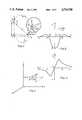
- FIG. 1is a schematic line diagram including an enlarged detail portion depicting certain parameters associated with a transmitter and receiver location system employing features of the present invention
- FIG. 2is a plot of received normalized vertical magnetic field intensity Hv vs distance in the Z direction of FIG. 1,
- FIG. 3is a plot similar to that of FIG. 2 depicting the horizontal magnetic field component
- FIG. 4is a cartesian coordinate plot depicting a magnetic moment M and specifying certain parameters of the resulting magnetic field
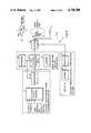
- FIG. 5is a schematic block diagram of a magnetic field transmitter (source) incorporating features of the present invention
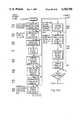
- FIG. 6is a schematic block diagram of a magnetic field receiver (sensor) incorporating features of the present invention
- FIGS. 7-14are schematic line diagrams depicting various arrangements of transmitter and receiver stations for practicing the present invention.
- FIG. 15is a computer program logic flow diagram depicting the logic of a portion of a program employed for practicing the present invention.
- FIG. 16is a computer program logic flow diagram depicting the logic for a second portion of a program used in practicing the present invention.
- FIGS. 17A-17Bis a computer program logic flow diagram depicting the logic for a gradient calculation subroutine of a program used in practicing the present invention.
- FIG. 18is a diagram similar to that of FIG. 4 depicting a two pole flux source.
- the transmitter locationmay be determined from coded or uncoded propagating electromagnetic waves.
- a conducting mediumsuch as the earth or water
- rapid exponential signal attenuationresults from energy dissipated through currents generated in the medium. It has been shown in the aforecited U.S. Pat. No. 3,967,201 that low frequency magnetic fields are a very effective means for communicating in a lossy medium. If appropriate total complex vector measurements are made of these magnetic fields, the relative position and orientation of the transmitter and receiver can be calculated.
- the radial and tangential magnetic field strength (Hr and H0 in polar coordinates) components at the receiverwhich result from a small magnetic dipole antenna, with a moment m, operating through a steel casing, with an attenuation A, located in the earth, with absorption parameter ⁇ , are as follows:
- low frequencies F(below 1 kHz and generally 1-100 Hz) are typically used so that for typical values of earth's conductivity, (0.001-0.1 S/m) the ranges, r, of interest (less than a few 1000 m) are significantly less than the earth's skin depth, ⁇ , so the absorption in the earth is negligible.
- the presence of an intervening metal structuresuch as steel casing, can result in appreciable attenuation A. It can be shown that the effect is equivalent to that of a source with the same location but smaller amplitude than without the casing.
- the relative location of the transmitter(s) and receiver(s)can be calculated without any knowledge of the attenuation, or even the dipole moment magnitude, if it is uniform over the paths of interest. Multiple frequencies may be used to resolve the attenuation in those cases where attenuation is nonuniform. By using relatively low operating frequencies, the attenuation can be minimized so that it does not seriously deteriorate system performance.
- the magnetospheric or "micropulsation” noisethat is generally predominate only below 2 Hz, should be added to the atmospheric noise model.
- magnetospheric noiseeven though it rises very rapidly below 2 Hz, is only of concern in very special cases since the optimum frequency for most location problems is generally above this value.
- the low-frequency end of the "1/f' modelshould be modified to incorporate the Schumann resonances. As illustrated by Evans and Griffiths in the reference cited above, the first three modal peaks at 8, 14, and 20 Hz would be somewhat above the "1/f' model, while the troughs at 5, 11, and 17 Hz would be well below it.
- the vertical component of noiseis generally considerably smaller than the horizontal component, typically by 10 to 20 dB.
- the application of frequency selection, impulse noise processing, and possibly long baseline cancellationmight lower the "1/f' model by 20 dB.
- the location errorsare a function of the signal-to-noise ratio (SNR) of the magnetic field strength measurements and the field distortions caused by inhomogeneous conditions.
- SNRsignal-to-noise ratio
- the preferred frequency for locationin such that the earth's skin depth is on the order of or greater than the operating path length at the maximum operating frequency to minimize attenuation and distortion effects due to the conducting medium.
- the operating frequencyis increased significantly above this point, the attenuation in the conducting earth increases rapidly. Although the most common noise conditions tend to decrease with increasing frequency, the rate is lower than the signal reduction.
- the optimum frequencyis essentially that which maximizes the ratio of received signal-to-noise density for the given (or assumed) profile of transmitter moment vs. frequency, propagation loss, and noise model as shown in the aforecited Pat. No. 3,967,201.
- accuracyis constrained by the same signal-to-noise ratio as for communication, although a much higher value (approximately 40 dB compared to approximately 10 dB) is required.
- the same optimum frequencywill result. In the real world, inhomogeneities and scattering obstacles could modify this choice in a very complicated manner.
- the optimum frequencywill always be reduced to a value where the unpredictable scattering is comparable to the additive noise.
- the frequencymay have to be increased to reduce scattering.
- the optimum frequencywill depend on the magnitude of the transmitting moment as well as on the noise spectrum, since scattering "noise" is multiplicative rather than additive.
- the optimum frequency for scattering alonemay not occur at zero frequency. In practice, however, a frequency of a few hertz is sufficient to greatly reduce ferromagnetic concentration effects, at least in the mines where this technique has been employed.
- the specific operating frequencyis chosen to minimize the effects of the ambient noise, the conducting medium and inhomogeneities in the medium.
- Any signal acquisition methodmay be used which minimizes noise effects and produces an accurate measurement of the signed signal amplitude.
- the exact signal phase angle, as distinct from polarity,is often determined to achieve the advantages of synchronous detection but it is not necessary for the calculation of location.
- One example of a cross-correlation methodis described in the following but there are many others.
- Suitable processing of noisy datashould be employed in order to achieve satisfactory location accuracies for practical applications.
- the data processing steps for the problemcan be divided into two general categories:
- the signal to be processedis provided as a sequence of amplitude samples taken at times t n and can be represented in the form
- v(t n )the sample value at time t n
- n(t n )additive noise value at t n
- ⁇phase of desired signal with respect to arbitrary time epoch established by the sampling
- ⁇signal frequency--presumed known.
- an estimate for the two parameters A and ⁇can be obtained. This can be done by fitting a sinusoid to the samples, and determining the sinusoid parameters that lead to a minimum squared error fit. (This process is equivalent to synchronous detection followed by an integrating filter). The error of the fit for each sample is expressed by
- Two data collection approachesare possible (1) Collect and sum into an array of storage registers the samples from corresponding points on each successive sample, and in a second array the number of samples deleted from each sampling point.
- Nthe total number of samples
- (2)multiply each sample by the appropriate trig values as the sample is taken, and form the sums a, b, c, d directly.
- the trade-offis that (1) requires more memory while (2) requires more computing time per sample.
- the a.c. field components observed as a function of the linear displacement of the moving (or multiple) itemwill always be a linear combination of three basic forms, known as the Anderson functions, regardless of the direction of motion or orientation. Two of these functions, normalized to unit moment and unit distance of closest approach, are illustrated in FIGS. 2 and 3.
- the process of computing the transmitter locus from datathen reduces to correlating data from each axis with these three functions, for various trials of vector moment and closest approach distance and time (position), until maximum correlations are found.
- the mechanisms of this processrequire an initial estimate of all parameters, then iteration of trials varying each of the parameters for a best fit.
- the direction, or bearing azimuth ( ⁇ ), of the transmitter locus from the receiveris given directly by the direction of the horizontal field
- Quadrant resolutionmust be determined by observation of the relative polarity of the three field components with respect to the antenna phase.
- the distance D, or range, of the transmitter locus from the receivercan be determined in several ways.
- the valuecould be obtained from the derivative of the horizontal field at its peak, as inferred above, but the peak is too broad to permit any more than a rough estimate in practice.
- the rangecan be determined from the field zeroes, that occur at Z A , Z B , Z 0 using the relationships ##EQU12##
- An iterative calculation procedurecan be used to improve the accuracy by correlating data points to find a best fit with the theoretical curve and to automate the entire data reduction process.
- This methodcan also be used to solve for the locus of a linear bore of unknown inclination if the transmitter moment and direction remains constant, and a curved bore by assuming it consists of segments of a circular arc.
- Inclinometerscan be used when it is not possible to control the vertical orientation of the transmitter or receiver.
- the locuscan be determined from the data after the fact.
- the receivermust be located ahead of the transmitter, within the core having an angle of 54.7° with respect to the transmitter axis, to avoid unresolvable ambiguities for steering.
- the steering direction to an intercept point at the receiver locationcan be determined from the ratio of the measured fields, appropriate for the geometry, as suggested by Equation 14. Although some combinations of offset and orientation will cancel at a given range, the process will converge as drilling progresses. If the receiver is offset from the planned locus, but still within the core of unambiguous operation, or a specific steering radius is required, the steering direction to stay on track can be determined by a combination of the received fields and an independent measurement of transmitter inclination and/or azimuth depending on the geometry.
- Transmitter locationcan be determined from calculations using measurements of the total complex vector field from at least two stationary receiver (or transmitter) stations. Although the computations are very involved, particularly when dealing with low quality data, they can readily be done by using integrated circuit microprocessors in equipment that is designed for easy field use.
- the methodis based on the fact that the vector properties of the magnetic field generated by a dipole transmitter can be used to locate the transmitter directly, without requiring any sort of search pattern. Assuming a rectangular coordinate frame, and a transmitter within that frame located at x, y, z, and generating a magnetic dipole moment with components m x , m y , m z , then the components of the magnetic field vector at any point 1 in the space can be written
- Measuring (receiving, detecting and quantifying) the magnetic field in two distinct locations or from two sourcesgenerates two such sets of equations, resulting in six simultaneous equations in the six unknowns x, y, z, m x , m y , m z .
- this setcould then be solved to yield not only the position of the transmitting antenna but its orientation and signal strength as well.
- the functions fare highly nonlinear, the six simultaneous equations cannot be solved directly.
- a number of iterative solution techniquescan be used to solve this set of equations that are suitable for use by a programmable calculator. In each case the computation begins with an initial estimate of the solution, which need not be accurate, and then converges toward the correct solution of the given set of equations.
- the primary advantage of this approachis that it gives both the location and orientation of the transmitter with a minimum number of measurements. More than two measurements may be desirable under poor conditions in order to minimize uncertainty by doing a best fit analysis or to eliminate ambiguities for certain loci of transmitter position.
- a dipole source model of the magnetic field transmitting antennais often used for computation in applications where the distances to the sensor are large compared to the dimensions of the transmitting antenna.
- mdipole moment
- ⁇azimuth
- ⁇elevation
- x,y,zposition
- f ijwhile all of the same form, will be parametized by x i , y i , z i . If a fit error defined as the sum square error of each component is established at each sensor then ##EQU13## where H ij is the measured value at the i th sensor in the j th direction and f ij is the predicted value for a given set of six source parameters. (A weighting function can be added to the fit error by multiplying each term of the summation by an arbitrarily selected constant A ij .) This can be minimized by simultaneously setting to zero
- the Gradient Projection method of sucessive approximationsis applied directly to the expression for ⁇ . Constraints, based on a priori knowledge of where the solution cannot lie, may be incorporated to limit the field of search.
- Convergence of the procedurecan be detected either by noting that each of the gradient vector components is acceptably close to zero, or by noting that the value of ⁇ is changing by only an infinitesimal amount on each iteration indicating its arrival at its asymptotic value.
- a constraint prohibiting the solution from lying in some area of the state spacecan be specified in the form of an inequality like
- Iis the six by six identity matrix and the matrix N is composed of those column vectors N i corresponding to the constraint surfaces we have hit. (In most cases the matrix N will have only one column corresponding to only one constraint surface.)
- FIG. 18there is shown an alternative method using two magnetic poles (plus and minus) instead of a dipole transmitter antenna model for computation of location. This method reduces errors at a short range.
- the model of FIG. 18 and the method of using the two magnetic poles instead of the dipoleis described as follows:
- the magnetic flux sourceis of magnitude ⁇ (webers) and is assumed to radiate isotropically.
- the pole separationis 2D, a known quantity, and leads to the expression
- the Initialization Routinepermits the entry of a number of values which define the system geometry and control parameters as follows:
- SNRMinimum signal-to-noise ratio
- the operatoris able to command a Verify Routine which allows the review and modification of previously entered data.
- the programmay also be restarted or terminated at this point.
- the programUpon entry of a Continue command, the program initializes information for a Data Acquisition Routine. This information includes the number of sensors and previously determined information such as system gains, number of samples per signal period and the number of signal periods to be measured. The Data Acquisition Routine then accumulates data as instructed and processes it to compute signal amplitude, phase and signal-to-noise ratio. (Note that manual entry of data is an alternative procedure.) If the SNR is below the specified level, additional data is accumulated and added to the previous data. When the SNR threshold is reached, the process of computing the transmitting source location and orientation can begin.
- the location and orientation calculationis an iterative process where one or more of the six source parameters (X, Y, Z, Az, El, m) are adjusted on each iteration.
- An output of the computationcalled EPSILON, is an error function which is a measure of how well a set of predicted measurements computed from the estimated source parameters fit the measured data. This process is repeated until the error function is reduced to the specified level.
- the computed "best fit" source location and orientationis displayed.
- a tolerance on each source parametercan also be determined as a function of the final error value and geometry.
- the programre-enters a command mode where the present data may be processed with revised limits or a new set of data may be taken and processed.
- GRDCALGradient Calculation
- this subroutineWhen this subroutine is called, it first computes the sin and cos functions of the source azimuth and elevation from the source data (either first best estimate or last iteration) and frequently used products of these trigonometric functions.
- the X, Y and Z components of the field vectorare computed from the source amplitude, azimuth and elevation and the 6 error slope accumulators are cleared.
- a "DOLOOP"is then entered which is executed once for each sensor in the system.
- Rangethe Range
- FX, FY, FZthe field values for each axis
- the first derivatives of each field component with respect to each of the six source parametersare computed, followed by computing the differences in measured fields and computed fields for each axis (HXMFX, HYMFY, HZMFZ).
- the contributions of that sensor to the six error slopesare determined and added to the error slope accumulators.
- the error value for that sensoris determined and stored.
- the total field erroris computed by summing the field error of each sensor. This value is then compared to the field error from the last iteration. If the new error is larger, the new error is replaced by the old error times a factor where the factor is less than 1.0 to prevent error oscillation and thus solution oscillation.
- the error slopes for elevation and azimuthare then weighted to make them comparable to the slopes for X, Y, and Z in terms of relative contribution to the error.
- the delta values for those slopes less than the maximum slope by some factorare set to 0.
- the delta values for the remaining slopesare, in this particular example, set as follows:
- Each ⁇ Vis then multiplies by its respective gain and divided by the number of nonzero deltas. Dividing by the number of nonzero deltas simply reduces the gain when more than one change is made, preventing large overshoots.
- Apprendix BA specific example of a solution of the field equations of Eqs. (17) for the case of FIG. 7 using the computer program of Appendix A is given in Apprendix B.
- the program of Appendix A and FIGS. 15-17is entered at the point of the functional box labeled "input control parameters" of FIG. 15 at which point the real data from the sensors, etc., is inputted manually and the program bypasses that portion of the flow diagram intervening between that functional point and "CALL GRDCAL" of FIG. 16 so that, the program listing picks up again at "CALL GRDCAL".
- the fields entered as dataare those calculated from these parameters.
- the initial trial parameters given the computerare:
- the location equipment of the present inventionincludes one or more transmitters 11 of the type shown in FIG. 5 which serve as the source of the oscillating magnetic field H, and one or more receivers 12 shown in FIG. 6 which serve to measure the resulting magnetic fields.
- the transmitter 11consists of a magnetic field antenna 16 along with the electronics and power source to drive it.
- the antenna 16may be an air core loop 16a, e.g., in planar form or a ferromagnetic core loop 16, e.g., in solenoid form as described in the aforecited U.S. Pat. No. 3,967,201. These loops each produce a magnetic field pattern equivalent to those for an infinitesimal dipole at distances that are large compared to the antenna dimensions.
- a measure of the transmitter source field strength and field directionis given by the equivalent magnetic dipole moment in terms of Ampere ⁇ Turn ⁇ Meter 2 and a vector direction normal to the plane of the loop.
- a slightly different field modelis useful such as two opposite monopoles separated by a distance, d, when working relatively close to a long solenoid (see FIG. 18).
- the primary advantage of the ferromagnetic core antenna 16is that it produces a relatively large dipole moment in a compact solenoid configuration that is ideal for borehole use, and it is the only practical way to generate sufficiently large signals in the majority of underground applications.
- the transmitter 11includes an oscillator 13 which, in a preferred embodiment, includes a crystal for precisely controlling the operating frequency to parts per million per degree centigrade.
- the oscillator output frequencyis preferably within the range of 1 to 1000 Hz and its output is fed to a high efficiency transmitter drive 14, the output of which is coupled via coupler 15 into transmitting antenna 16.
- the inductive antennais driven with an alternating current by the high efficiency electronics 14 that may be of the direct switching, resonant capacitor storage or other type depending on the application.
- the efficiencycan be optimized by tailoring the drive voltage and current, the winding loss, the ferromagnetic core loss, and the other electronic loss to suit a given application.
- One or more antennas 16may be coupled to the output of the coupler 15.
- the antennas 16may have their axes oriented in a certain relationship, i.e., orthogonal, depending upon the particular circumstances of the location system being employed.
- accessory navigation componentsi.e., tiltmeters, magnetic compass, etc.
- communication functionsmay be employed with the transmitter to provide that such accessory information is either superimposed upon the transmitted magnetic fields as by modulation or the accessory information may be fed from the respective function generators via a separate communication link to the receivers 12 or to a central location where the location computations are to be performed.
- the accessory navigation of uplinked communication functionsinclude a two or three-axis tiltmeter, the outputs of which are fed into a multiplexer and A to D converter 17 and thence into the input of a modulator 18 which serves to modulate the phase of the transmitted oscillating magnetic field.
- Other monitoring and logging functionssuch as temperature sensing, static magnetic (earth) field direction, etc., may have their inputs fed into the multiplexer and A to D converter 17 and similarly modulated onto the transmitted magnetic field. (This information can be communicated directly when a wireline is used to drive the antenna.) The information may be digitized and encoded in a pseudo noise format for efficient communication under poor signal to noise conditions.
- Batteries 19may be employed at the transmitter station for suplying power to the various power consuming units or, as an alternative, power may be supplied from a central source via a wire or cable.
- the transmitting antenna 16may also be operated by wireline from some remote location.
- an auxiliary down-link command or communication functionmay be performed by means of a receiver 21 coupled to the antenna 16 via coupler 15 and the output of the receiver being fed to a decoder 20 which decodes the information received by the antenna.
- the decoderoutputs the decoded information to the appropriate circuit functions.
- the receiver 12includes the basic magnetic field sensor 22 such as a one to three-axis magnetic field vector sensor 22.
- a sensormay comprise, for example, a magnetometer of some type such as a flux gate, superconducting etc., or a search coil, i.e., loops of conductors.
- the magnetic field sensor 22may include a one to three-axis tiltmeter coupled thereto and tiltable with the field sensor 22 so as to derive the orientation of the field sensor relative to the earth's gravitational field.
- the output of the magnetic field sensor 22is fed to a wide band filter and amplifier 23 for filtering and amplification and the output of the amplifier is fed to a multiplexer and analog-to-digital converter 24 for quantifying the tiltmeter readings, if present.
- the transmitter 11 and receiver 12 operating frequency stabilityis controlled to permit coherent (amplitude and phase) detection under noisy signal conditions.
- the digitized and multiplexed outputs from the multiplexer 24are fed to the input of a data transmission system such as a wireline, radio frequency transmitter or the like 26 for transmission to the data reduction equipment including a digital processor 27.
- a data transmission systemsuch as a wireline, radio frequency transmitter or the like 26 for transmission to the data reduction equipment including a digital processor 27.
- more than one set of magnetic field sensors 22are employed in which case the outputs from the other sensors 22 are fed into the digital processor 27 via a digital multiplexer 28 which multiplexes all information derived from the various sensors.
- the digital processor 27includes a microprocessor, APU, ROM, RAM, etc.
- a keyboard and display 29is interactively coupled with the digital processor 27 and a printer or graphic plotter 31 is interactively coupled with the keyboard and display 29 for printing out and plotting data derived from the keyboard 29 and digital processor 27.
- the weak fields measured by the sensor 22undergo some filtering, amplification (with automatic gain control to track varying conditions) and digitizing right at the remote detector location prior to communication with the main portion of the receiver or data reduction equipment.
- the various channels of informationare multiplexed into a digital processor 27 such as a microprocessor based computing system.
- the important signal processing functions of impulse noise editing, filtering the signals to suitable quality, noise evaluation, coherent detection to determine phase and amplitude, and decoding any information transmittedare then performed digitally from software programs prior to doing the location calculations.
- the location calculationsare performed after the receiver (or transmitter) location and alignment reference information is entered with the keyboard 29 or alternatively in fixed installations, with a programmable read only memory (PROM). The results are presented on the display 29, printer 31 or graphics plotter 31.
- a microprocessor right at the remote sensor(s)for doing all of the signal processing prior to transmission to the central computer 27 (or for doing the entire location calculation) and transmitting only the results when communication channel capacity is limited.
- the basic receiver 12can also be implemented by using conventional hardware techniques for the filtering and coherent detection functions, etc., and the location calculations can be done using a programmable hand calculator.
- the data reduction functionsare often included in the sensor data unit.
- the computed steering or location informationmay then be transmitted to a remote display 32.
- Either the transmitter(s) or the receiver(s)may be the unknown (u) with the other being the known (k).
- one single axis transmitting antenna 16is usually used at the unknown location (u), e.g., in a borehole or at a drill bit.
- the receiver 12is usually located for direct operator access since it is easier to very precisely align the relatively small receiver sensors and to limit noise induced by mechanical motion of the sensor 22 in the earth's field.
- the rolescan be reversed, through appropriate system design, to suit the needs of specific applications.
- an array of some appropriate combination of transmitter and receiver elements 11 and 12is used to obtain enough information for calculating the relative orientation and position of the array elements.
- the two three-axis receivers 12, of known orientation and location (k)may be used to determine the orientation and location of an unknown single axis transmitter T(u).
- Other combinationsare possible as described below.
- the best accuracywill be achieved when the span between the known array elements (e.g., receiver or transmitter stations) is on the order of the distance between the known array and the unknown.
- one or more three-axis sensors 22are used to measure total vector field and are positioned and aligned with respect to some surveyed reference location. This may be accomplished manually by using a transit or automatically by using techniques described below. Two or more sensors 22 may also be pre-mounted on a rigid beam, when the practical spans are adequate, to maintain accurate relative alignment or simplify field set-up. This also facilitates the use of two or more sensors 22 as the unknowns R(u) in inaccessable locations.
- Various featurescan be incorporated to simplify or automate the alignment process or to aid the location calculation process.
- sensitive two or three-axis tiltmeterscan be used to eliminate the need for manual leveling, and the information used to calculate vertical orientation with respect to any set of reference coordinates.
- the earth's magnetic fieldcan be used to determine azimuth for automatic correction of rotation. In both of these cases it is still desirable to accurately measure position when the receiver 12 is the known reference R(k).
- R(k)the known reference
- two or more reference transmitters T1(k), T2(k)can be installed at a convenient and precisely surveyed location or locations which will permit automatic calculation of receiver position and orientation.
- the receiver(s)can then be located as the unknown then used to determine the position of another, unknown transmitter.
- the orientation of the transmitting antenna's major axis (loop axis) and the antenna locationcan be determined from the field measurements.
- the rotation of the antenna about its major axis(commonly referred to as the tool face angle in drilling) cannot be directly determined. Except in near vertical holes, rotation may be determined when necessary by adding a two or three-axis tiltmeter to measure orientation with respect to vertical and transmitting this information to the receiver 12 by means described above.
- Integral tiltmeterscan also be used as a cnvenient accessory in certain applications such as aiding the calculation of the unknown transmitter location under very noisy conditions or for determining vertical profile with a single sensor or in aligning the transmitter when it is used as a known reference T(k).
- Co-located two and three-axis transmitting dipolesare an alternative method for determining rotation as well as being useful in other applications described below.
- the mechanical factors involvedprimarily have to do with the alignment and location survey precision of the basic reference used whether it's the receiver(s) or transmitter(s) in the particular application. Mechanical factors can generally be controlled to achieve sufficiently accurate measurements, in practical applications, unless initial hardware cost is a major consideration in which case performance tradeoffs may be necessary.
- the electrical factors involvedare much more diverse and uncontrollable. The effects of attenuation, scattering in a highly inhomogenous conducting medium, distortion by magnetic materials and mechanically induced noise have already been mentioned. Magnetic noise from extraterrestrial sources, worldwide thunderstorm activity and electric power line transients is also one of the major functions which limit system performance. The effects of these factors are minimized through suitable choice of operating frequency, signal processing methods and control or measurement of the reference set-up.
- someare capable of the complete solution for six unknowns.
- Othersrequire either specification of some parameters (e.g. moment, one component of transmitter orientation, one component of transmitter position) or some constraint, such as the assumption that the axis orientation of a moving transmitter, although unknown, is invariant or follows a known constraint such as a circular arc.
- Some casesmay be overspecified, that is, more measurements are obtained than there are degrees of freedom.
- a best fit to the known constraintsshould be applied to make use of all available data, since the measurements are known to be noisy. Even in cases that are not overspecified (measurements match unknowns), due to the inevitable errors in data, a best fit approach is employed rather than seeking an exact solution, which may not exist.
- FIGS. 7-9there is shown a class of cases utilizing one single axis transmitter and plural three-axis receivers. This is an important case, as it is a method useful in borehole surveying, river crossing drill guidance, pipeline tunneling guidance, mine surveying, and shaft location.
- the solutionis generally completely specified by the data, meaning, that the six measurements of field (3 axes ⁇ 2 locations) allow simultaneous solution of six equations (three for each receiver) of the type of Eqs. (17) for all six unknowns by the field calculation method described herein.
- a ferromagnetic-cored solenoid 16is capable of generating a much larger magnetic moment in the axial direction than in the radial directions, and a very much larger axial moment than any nonmagnetic-cored coil 16a, for the same power input.
- the magnitude of the transmitter magnetic momentneed not be known a priori to complete the solution, which includes computation of the moment from the data. This is important for use in cased holes, where the effective moment "seen" outside the casing by the receiver 12 is an attenuated version of the moment actually produced by the transmitter 11 inside the casing. This attenuation is a function of the diameter, thickness, electrical conductivity, and magnetic permeability of the casing, and of the frequency and position of the transmitter inside it. In some applications, such as a transmitter fixed inside a drill head which will be beyond the casing in operation, the attenuation can be calibrated by measurement and then considered invariant. In other cases, such as surveying an already cased hole, the attenuation is not only unpredictable but may vary along the length of the hole due to multiple casings, different materials used in different sections, corrosion, etc.
- the orientation of the transmitter magnetic momentneed not be known a priori to complete the solution, which includes computation of this orientation from the data. This is important in cased holes, where the effective moment orientation may be distorted by non-uniform attenuation, or by the position of the transmitter within the casing. It also provides a by-product of direct measurement of the drill orientation in casing-free operation.
- Computation for this general caserequires knowledge of the (relative) position of the two receiver sensors 22, and the orientation of their axes with respect to their baseline (the line connecting the centers of the sensors) and one other independent direction, such as the vertical, which together define a sensor coordinate base.
- the position and orientation of the transmitterare then calculated in this sensor (receiver) coordinate base; to the extent that the sensor coordinate base origin and orientation are known in some other reference coordinates, to within the additional accuracy of the location system.
- This accuracyis in turn determined by the magnitudes of the moment and the local noise level; the time available for measurement; the geometry (spacing between sensors 22 and from each sensor 22 to the source 16); and the accuracy with which the gain and orientation (within the sensor coordinate base) of each sensor axis are known.
- the location of the transmitter Tmay be unknown (u) and computed, given the known location (k) of the receivers R 1 and R 2 .
- the location of the receivers R 1 and R 2may be computed from knowledge of the known position (k) of the transmitter T and measurements of the magnetic field components derived from the receivers R 1 and R 2 and the coordinate system defined by R 1 and R 2 .
- the reciprocal arrangement of FIG. 8is also useful, i.e., the location of the T(u) can be computed from data derived from the known location of the receivers R 1 and R 2 .
- FIG. 10there is shown a class of cases which can be considered the reciprocal of the case for FIGS. 7-9 and, more particularly, a class of cases wherein one single axis receiver is utilized with a pair of three-axis transmitters.
- This exampleis particularly useful in mining and relies upon the fact that the position of the first transmitter T 1 is known relative to the position of the second transmitter (T 2 ) to define a coordinate system for determining the relative location of a receiver at an unknown (U) location.
- the position of the transmitters relative to the receivermay be calculated, again assuming that the position of one transmitter relative to the other is known such as the transmitter being co-located on a single beam or structure, the axes of the first and second transmitters being known relative to each other.
- FIG. 11there is shown a class of cases employing a pair of distinctively encoded (e.g. time shared, frequency separated or otherwise encoded) single-axis transmitters and one three-axis receiver.
- the relative position of the two transmitters T 1 and T 2is known to define a reference set of coordinates.
- the location of the transmitter stationsmay be known to derive the unknown location of the three axes receiver or, in the alternative, the position of the three axes receiver may be known to determine the location of the single axis transmitters, T 1 and T 2 .
- FIG. 11is particularly applicable to surveying deep boreholes by deploying two separated transmitting loops 16a on the surface or sea floor, capable of producing the very large moments needed for deep penetration.
- the source locations, moments, and orientationswill be determined by measuring their fields at multiple known locations, as in the cases of FIGS. 7-9.
- This methodusually results in complete specification of the problem in six unknowns, e.g., both source loops 16a and the sensor 22 location all co-planar, with unknown attenuation.
- the location and orientation of a three-axis receiver sensor 22 in a boreholemay be determined by transmission of received or processed data from the receiver 12 to the surface either by wireline or by telemetry.
- the location of the transmitters T 1 and T 2can be calculated from the field measurements derived from the three axes receiver sensor 22.
- FIG. 12there is shown a case employing a single, distinctively encoded, two-axis transmitter and a single three-axis receiver for determining relative location of the transmitter station relative to the receiver station.
- the orientation of the transmitteris known and the moment of the transmitter is known.
- the unknown position of the three-axis receiver (R)can be calculated from the field measurements derived from the receiver.
- the location of the two-axis transmittercan be calculated from field signals derived from the receiver.
- the two axes of the transmitterare preferably nearly perpendicular and the transmitting antennas 16 are co-located.
- FIGS. 13 and 14there is shown a class of cases employing only one single-axis transmitter and one three-axis receiver.
- FIG. 13a case is shown wherein the single-axis transmitter T is moved to two or more unknown locations, e.g., lowered in known steps down a borehole and a single three-axis receiver sensor 22 is positioned at a known location.
- FIG. 13The case of FIG. 13 is useful for locating cased vertical shafts relative to drifts.
- An iron-cored solenoid transmitter antenna 16, driven by wireline from the surface,is lowered in measured steps down the shaft, and three axes field measurements are made by a fixed receiver sensor 22 in the drift for each transmitter location, T, T', etc.
- the casing attenuation and, therefore, the effective transmitter moment,are unknown.
- the transmitter antenna orientationto be known (vertical)
- no single location of the transmitteris completely specified, since there are four unknowns (3 in position; 1 in moment) and only three measurements.
- it is assumed that the transmitter momentis constant, vertical, and moved in known steps on a vertical axis.
- FIG. 14athere is shown a special case for the class of FIGS. 13 and 14 wherein a single axis transmitter T of known location, T(k) orientation and moment is employed with a three-axis receiver sensor 22 of know orientation.
- This methodis particularly suitable for deep hole surveying, similar to the embodiment of FIG. 13, but when the receiver sensor orientation is known, such as by incorporation of tiltmeters and a magnetic compass at the receiver location (which may use the same magnetic sensor as the location system) in the downhole tool.
- the receiver sensor orientationis known, such as by incorporation of tiltmeters and a magnetic compass at the receiver location (which may use the same magnetic sensor as the location system) in the downhole tool.
- only a single transmitting antenna 16is required allowing the dedication of all available real estate to one large loop 16a for extremely deep holes, or restricted access on the surface.
- the position of the receiveris calculated from the magnetic field components received at the receiver station and the sensor orientation information.
- a single-axis transmitter (T) of unknown (u) locationis employed in a drilling assembly and a single three-axis receiver sensor 22 is positioned within a core (eg 45° half angle) ahead of the drill at a known (k) location (e.g., on the surface or in a tunnel or borehole) and generally in the plane of the hole being drilled.
- a calibrated transmitter moment and continuous measure of its inclination (by wireline on modulation of the navigation signal) or length of the drill string in the holea predetermined vertical profile can be followed by calculating the depth and steering accordingly.
- An alternativeis to use the inclination and length of drill string only for vertical steering.
- Horizontal steeringcan be achieved by using a magnetic compass or the horizontal magnetic field components received at the sensor station. If the sensor is at the final target location, the received fields can be used to steer the drill straight toward an aligned sensor or in an arc toward an inclined sensor (mechanically or electrically rotated) without knowledge of moment, inclination or pipe length.
- the locus of the final boreholecan be calculated by the iterative "best fit" process using data collected during drilling.
- FIG. 14cAn alternative is shown in FIG. 14c in which the single three-axis receiver sensor 22 is at the unknown (u) location in the drill assembly and a single-axis transmitter is positioned at the known (k) location.
- This configurationhas advantages when it is desired to use the sensor as a magnetic compass and a receiver but vibration-induced noise will usually preclude its use while actually drilling.
- more than one transmitter frequencymay be employed to resolve propagation attenuation problems.
- the transmittersmay be switched in an unambiguous sequence (e.g. off, A, B) to provide reference information to the receiver sensor 22.
- the receiver sensor 22may be adapted for sensing the static magnetic (earth) field to define receiver sensor orientation. This information may be utilized in the calculations deriving the position of the unknown transmitter or receiver stations. Also with regard to the receiver station, the receiver sensors 22 may be mounted on a common beam to control relative alignment and spacing therebetween. ##SPC1## ##SPC2## ##SPC3##
Landscapes
- Physics & Mathematics (AREA)
- Engineering & Computer Science (AREA)
- Life Sciences & Earth Sciences (AREA)
- Geology (AREA)
- Remote Sensing (AREA)
- General Physics & Mathematics (AREA)
- General Life Sciences & Earth Sciences (AREA)
- Mining & Mineral Resources (AREA)
- Environmental & Geological Engineering (AREA)
- Geophysics (AREA)
- Electromagnetism (AREA)
- Fluid Mechanics (AREA)
- Geochemistry & Mineralogy (AREA)
- Radar, Positioning & Navigation (AREA)
- Geophysics And Detection Of Objects (AREA)
Abstract
Description
H.sub.r =(Am/2πr.sup.3)Γ.sub.r cos θ Eq. (1)
H.sub.θ =(Am/4πr.sup.3)Γ.sub.θ sin θEq. (2) ##EQU1## and the skin depth δ=(πfμ.sub.o σ).sup.-1/2 ; in MKS units μ.sub.o =4π×10.sup.-7 H/m.
v(t.sub.n)=A sin (ωt.sub.n +φ)+n(t.sub.n) Eq. (3)
ε.sub.n =v(t.sub.n)-A sin (ωt+φ) Eq. (4)
sin (a+b)=sin a cos b+cos a sin b
ε.sup.2 =f-2A(b cos φ+a sin φ)+(A.sup.2 /2)[(N-K)+c cos 2φ-d sin 2φ]
∂ε.sup.2 /∂A=-2(b cos φ+a sin φ)+A[(N-K)+c cos 2φ-d sin 2φ]
∂ε.sup.2 /∂φ=2A b sin φ-2A a cos φ-A.sup.2 c sin 2φ-A.sup.2 d cos 2φ
2(b sin φ-a cos φ)=A(c sin 2φ+d cos 2φ)
[-b(N-K)-ad+bc] sin φ=-[a(N-K)+ac+bd] cos φ
φ=arc tan (H.sub.y /H.sub.x) Eq. (14)
H.sub.1x =f.sub.1x (x, y, z, m.sub.x, m.sub.y, m.sub.z)
H.sub.1y =f.sub.1y (x, y, z, m.sub.x, m.sub.y, m.sub.z)
H.sub.1z =f.sub.1z (x, y, z, m.sub.x, m.sub.y, m.sub.z) Eqs. (16)
H.sub.ix =(1/4πr.sub.i.sup.5){m.sub.x (2x.sub.I.sup.2 -y.sub.I.sup.2 -z.sub.I.sup.2)+m.sub.y 3x.sub.I y.sub.I +m.sub.z 3x.sub.I z.sub.I }=f.sub.ixH.sub.iy =(1/4πr.sub.i.sup.5){m.sub.x 3x.sub.I y.sub.I +m.sub.y (2y.sub.I.sup.2 -z.sub.I.sup.2 -x.sub.I.sup.2)+m.sub.z 3y.sub.I z.sub.I }=f.sub.iyH.sub.iz =(1/4πr.sub.i.sup.5){m.sub.x 3x.sub.I z.sub.I +m.sub.y 3y.sub.I z.sub.I +m.sub.z (2z.sub.I.sup.2 -x.sub.I.sup.2 -y.sub.I.sup.2)}=f.sub.iz Eq. (17)r.sub.i =[x.sub.I.sup.2 +y.sub.I.sup.2 +z.sub.I.sup.2 ].sup.1/2
x.sub.I =x-x.sub.i y.sub.I =y-y.sub.i z.sub.I =z-z.sub.i
m.sub.x =m cos α cos β
m.sub.y =m sin β
m.sub.z =m sin α cos β Eqs. (18)
H.sub.ij =f.sub.ij (m, α, β, x, y, z) Eq. (19)
∂ε/∂m=∂ε/.differential.α=∂ε/∂β=∂.epsilon./∂x=∂ε/∂y=∂ε/∂z=0
∂f.sub.ix ∂x=(1/4πr.sub.i.sup.5){m.sub.x 4x.sub.I +m.sub.y 3y.sub.I +m.sub.z 3z.sub.I }-(5x.sub.I /r.sub.i.sup.2)f.sub.ix∂f.sub.ix /∂y=(1/4πr.sub.i.sup.5){-m.sub.x 2y.sub.I +m.sub.y 3x.sub.I }-(5y.sub.I /r.sub.i.sup.2)f.sub.ix∂f.sub.ix /∂z=(1/4πr.sub.i.sup.5){-m.sub.x 2z.sub.I +m.sub.z 3x.sub.I }-(5z.sub.I /r.sub.i.sup.2)f.sub.ix∂f.sub.ix /∂α=1/4πr.sub.i.sup.5 {-m sin α cos β(2x.sub.I.sup.2 -y.sub.I.sup.2 -z.sub.I.sup.2)+m cos α cos β 3x.sub.I z.sub.I }∂f.sub.ix /∂β=1/4πr.sub.i.sup.5 {-m cos α sin β(2x.sub.I.sup.2 -y.sub.I.sup.2 -z.sub.I.sup.2)+m cos β3x.sub.I y.sub.I -m sin α sin β3x.sub.I z.sub.I }Eqs. (23) ##EQU15##f.sub.1 (m, α, β, x, y, z)≦0
f.sub.1 (m.sub.n, α.sub.n, . . . z.sub.n)≦0
f.sub.2 (m.sub.n, α.sub.n, . . . z.sub.n)≦0 Eq. (25)
Q=I-N(N.sup.T N).sup.-1 N.sup.T Eq. (27)
Δx.sup.2 +Δy.sup.2 +Δz.sup.2 =D.sup.2 Eq. (29)
B.sub.i± =±φ/4πr.sub.i±.sup.2) Eq. (30)
r.sub.i±.sup.2 =[x.sub.i -(x±Δx)].sup.2 +[y.sub.i -(y±Δy)].sup.2 +[z.sub.i -(z±Δz)].sup.2 Eq. (31)
V=E.sup.P /SLOPE
Claims (20)
Priority Applications (1)
| Application Number | Priority Date | Filing Date | Title |
|---|---|---|---|
| US06/401,267US4710708A (en) | 1981-04-27 | 1982-07-23 | Method and apparatus employing received independent magnetic field components of a transmitted alternating magnetic field for determining location |
Applications Claiming Priority (2)
| Application Number | Priority Date | Filing Date | Title |
|---|---|---|---|
| US25764581A | 1981-04-27 | 1981-04-27 | |
| US06/401,267US4710708A (en) | 1981-04-27 | 1982-07-23 | Method and apparatus employing received independent magnetic field components of a transmitted alternating magnetic field for determining location |
Related Parent Applications (1)
| Application Number | Title | Priority Date | Filing Date |
|---|---|---|---|
| US25764581AContinuation-In-Part | 1981-04-27 | 1981-04-27 |
Publications (1)
| Publication Number | Publication Date |
|---|---|
| US4710708Atrue US4710708A (en) | 1987-12-01 |
Family
ID=26946096
Family Applications (1)
| Application Number | Title | Priority Date | Filing Date |
|---|---|---|---|
| US06/401,267Expired - LifetimeUS4710708A (en) | 1981-04-27 | 1982-07-23 | Method and apparatus employing received independent magnetic field components of a transmitted alternating magnetic field for determining location |
Country Status (1)
| Country | Link |
|---|---|
| US (1) | US4710708A (en) |
Cited By (304)
| Publication number | Priority date | Publication date | Assignee | Title |
|---|---|---|---|---|
| US4806869A (en)* | 1986-05-22 | 1989-02-21 | Flow Industries, Inc. | An above-ground arrangement for and method of locating a discrete in ground boring device |
| US4814768A (en)* | 1987-09-28 | 1989-03-21 | The United States Of America As Represented By The United States Department Of Energy | Downhole pulse radar |
| US4847773A (en)* | 1985-02-25 | 1989-07-11 | Industrial Contractors Holland B.V. | System for navigating a free ranging vehicle |
| US4875014A (en)* | 1988-07-20 | 1989-10-17 | Tensor, Inc. | System and method for locating an underground probe having orthogonally oriented magnetometers |
| US4881083A (en)* | 1986-10-02 | 1989-11-14 | Flowmole Corporation | Homing technique for an in-ground boring device |
| GB2243693A (en)* | 1990-05-04 | 1991-11-06 | Baroid Technology Inc | Guiding a tool along a subterranean path |
| US5065098A (en)* | 1990-06-18 | 1991-11-12 | The Charles Machine Works, Inc. | System for locating concealed underground objects using digital filtering |
| US5126654A (en)* | 1989-02-10 | 1992-06-30 | New York Gas Group | Non-invasive, high resolution detection of electrical currents and electrochemical impedances at spaced localities along a pipeline |
| US5133417A (en)* | 1990-06-18 | 1992-07-28 | The Charles Machine Works, Inc. | Angle sensor using thermal conductivity for a steerable boring tool |
| EP0481077A4 (en)* | 1989-06-30 | 1992-10-21 | Kabushiki Kaisha Komatsu Seisakusho | Device for measuring position of underground excavator |
| US5160925A (en)* | 1991-04-17 | 1992-11-03 | Smith International, Inc. | Short hop communication link for downhole mwd system |
| FR2679514A1 (en)* | 1991-07-23 | 1993-01-29 | Thomson Csf | PORTABLE STATION FOR MEASURING AND ADJUSTING THE MAGNETIC SIGNATURE OF A NAVAL VESSEL. |
| US5231355A (en)* | 1990-06-18 | 1993-07-27 | The Charles Machine Works, Inc. | Locator transmitter having an automatically tuned antenna |
| US5239474A (en)* | 1990-11-20 | 1993-08-24 | Hughes Aircraft Company | Dipole moment detection and localization |
| US5264795A (en)* | 1990-06-18 | 1993-11-23 | The Charles Machine Works, Inc. | System transmitting and receiving digital and analog information for use in locating concealed conductors |
| US5264793A (en)* | 1991-04-11 | 1993-11-23 | Hughes Aircraft Company | Split array dipole moment detection and localization |
| WO1994004938A1 (en)* | 1992-08-14 | 1994-03-03 | British Telecommunications Public Limited Company | Position location system |
| US5307072A (en)* | 1992-07-09 | 1994-04-26 | Polhemus Incorporated | Non-concentricity compensation in position and orientation measurement systems |
| EP0433407B1 (en)* | 1989-06-09 | 1994-05-11 | British Gas plc | Moling system |
| US5337259A (en)* | 1993-03-01 | 1994-08-09 | Hughes Aircraft Company | Dipole detection and localization processing |
| US5387863A (en)* | 1992-04-14 | 1995-02-07 | Hughes Aircraft Company | Synthetic aperture array dipole moment detector and localizer |
| US5453686A (en)* | 1993-04-08 | 1995-09-26 | Polhemus Incorporated | Pulsed-DC position and orientation measurement system |
| US5477210A (en)* | 1993-04-30 | 1995-12-19 | Harris Corporation | Proximity monitoring apparatus employing encoded, sequentially generated, mutually orthogonally polarized magnetic fields |
| US5485089A (en)* | 1992-11-06 | 1996-01-16 | Vector Magnetics, Inc. | Method and apparatus for measuring distance and direction by movable magnetic field source |
| US5512830A (en)* | 1993-11-09 | 1996-04-30 | Vector Magnetics, Inc. | Measurement of vector components of static field perturbations for borehole location |
| US5513710A (en)* | 1994-11-07 | 1996-05-07 | Vector Magnetics, Inc. | Solenoid guide system for horizontal boreholes |
| US5558091A (en)* | 1993-10-06 | 1996-09-24 | Biosense, Inc. | Magnetic determination of position and orientation |
| US5585790A (en)* | 1995-05-16 | 1996-12-17 | Schlumberger Technology Corporation | Method and apparatus for determining alignment of borehole tools |
| US5589775A (en)* | 1993-11-22 | 1996-12-31 | Vector Magnetics, Inc. | Rotating magnet for distance and direction measurements from a first borehole to a second borehole |
| US5640170A (en)* | 1995-06-05 | 1997-06-17 | Polhemus Incorporated | Position and orientation measuring system having anti-distortion source configuration |
| US5659985A (en)* | 1995-06-19 | 1997-08-26 | Vermeer Manufacturing Company | Excavator data acquisition and control system and process |
| US5720354A (en)* | 1996-01-11 | 1998-02-24 | Vermeer Manufacturing Company | Trenchless underground boring system with boring tool location |
| US5729129A (en)* | 1995-06-07 | 1998-03-17 | Biosense, Inc. | Magnetic location system with feedback adjustment of magnetic field generator |
| US5744953A (en)* | 1996-08-29 | 1998-04-28 | Ascension Technology Corporation | Magnetic motion tracker with transmitter placed on tracked object |
| US5787997A (en)* | 1995-11-21 | 1998-08-04 | Shell Oil Company | Method of qualifying a borehole survey |
| US5828219A (en)* | 1996-08-22 | 1998-10-27 | Radiodetection, Ltd. | Method of detecting faults in the insulation layer of an insulated concealed conductor |
| US5917325A (en)* | 1995-03-21 | 1999-06-29 | Radiodetection Limited | Method for locating an inaccessible object having a magnetic field generating solenoid |
| US5952958A (en)* | 1996-04-05 | 1999-09-14 | Discovision Associates | Positioning system and method |
| US5960370A (en)* | 1996-08-14 | 1999-09-28 | Scientific Drilling International | Method to determine local variations of the earth's magnetic field and location of the source thereof |
| FR2778746A1 (en)* | 1988-03-22 | 1999-11-19 | Crouzet Sa | Detection, location and identification of magnetic objects, using transducer in relative motion |
| US5990683A (en)* | 1991-03-01 | 1999-11-23 | Digital Control Incorporated | Method and arrangement for locating a boring tool using a three-antennae vector sum |
| US6035951A (en)* | 1997-04-16 | 2000-03-14 | Digital Control Incorporated | System for tracking and/or guiding an underground boring tool |
| US6054951A (en)* | 1995-08-28 | 2000-04-25 | Sypniewski; Jozef | Multi-dimensional tracking sensor |
| US6073043A (en)* | 1997-12-22 | 2000-06-06 | Cormedica Corporation | Measuring position and orientation using magnetic fields |
| US6147480A (en)* | 1997-10-23 | 2000-11-14 | Biosense, Inc. | Detection of metal disturbance |
| US6177792B1 (en) | 1996-03-26 | 2001-01-23 | Bisense, Inc. | Mutual induction correction for radiator coils of an objects tracking system |
| US6203493B1 (en) | 1996-02-15 | 2001-03-20 | Biosense, Inc. | Attachment with one or more sensors for precise position determination of endoscopes |
| US6211666B1 (en) | 1996-02-27 | 2001-04-03 | Biosense, Inc. | Object location system and method using field actuation sequences having different field strengths |
| US6223066B1 (en) | 1998-01-21 | 2001-04-24 | Biosense, Inc. | Optical position sensors |
| US6250402B1 (en) | 1997-04-16 | 2001-06-26 | Digital Control Incorporated | Establishing positions of locating field detectors and path mappings in underground boring tool applications |
| US6253770B1 (en) | 1996-02-15 | 2001-07-03 | Biosense, Inc. | Catheter with lumen |
| US6266551B1 (en) | 1996-02-15 | 2001-07-24 | Biosense, Inc. | Catheter calibration and usage monitoring system |
| US6285190B1 (en) | 1999-06-01 | 2001-09-04 | Digital Control Incorporated | Skin depth compensation in underground boring applications |
| US6316934B1 (en) | 1998-09-17 | 2001-11-13 | Netmor Ltd. | System for three dimensional positioning and tracking |
| US6321109B2 (en) | 1996-02-15 | 2001-11-20 | Biosense, Inc. | Catheter based surgery |
| US6332089B1 (en) | 1996-02-15 | 2001-12-18 | Biosense, Inc. | Medical procedures and apparatus using intrabody probes |
| US6335617B1 (en) | 1996-05-06 | 2002-01-01 | Biosense, Inc. | Method and apparatus for calibrating a magnetic field generator |
| US6341231B1 (en) | 1994-09-15 | 2002-01-22 | Visualization Technology, Inc. | Position tracking and imaging system for use in medical applications |
| EP1174082A1 (en)* | 2000-07-20 | 2002-01-23 | Biosense, Inc. | Electromagnetic position single axis system |
| US6366799B1 (en) | 1996-02-15 | 2002-04-02 | Biosense, Inc. | Movable transmit or receive coils for location system |
| US6373240B1 (en) | 1998-10-15 | 2002-04-16 | Biosense, Inc. | Metal immune system for tracking spatial coordinates of an object in the presence of a perturbed energy field |
| US20020075001A1 (en)* | 2000-08-30 | 2002-06-20 | Goodman William L. | Multi-axis locator for detection of buried targets |
| US6411094B1 (en) | 1997-12-30 | 2002-06-25 | The Charles Machine Works, Inc. | System and method for determining orientation to an underground object |
| US20020098868A1 (en)* | 1999-05-25 | 2002-07-25 | Meiksin Zvi H. | Through-the-earth communication system |
| US6427079B1 (en) | 1999-08-09 | 2002-07-30 | Cormedica Corporation | Position and orientation measuring with magnetic fields |
| US6427784B1 (en) | 1997-01-16 | 2002-08-06 | Mclaughlin Manufacturing Company, Inc. | Bore location system having mapping capability |
| US20020105331A1 (en)* | 1999-06-01 | 2002-08-08 | Brune Guenter W. | Multi-frequency boring tool locating system and method |
| US6445943B1 (en) | 1994-09-15 | 2002-09-03 | Visualization Technology, Inc. | Position tracking and imaging system for use in medical applications |
| US6453190B1 (en) | 1996-02-15 | 2002-09-17 | Biosense, Inc. | Medical probes with field transducers |
| US6459266B1 (en)* | 1999-01-26 | 2002-10-01 | Radiodetection Limited | Sonde locator |
| US6466020B2 (en) | 2001-03-19 | 2002-10-15 | Vector Magnetics, Llc | Electromagnetic borehole surveying method |
| US6487516B1 (en) | 1998-10-29 | 2002-11-26 | Netmor Ltd. | System for three dimensional positioning and tracking with dynamic range extension |
| US6498477B1 (en) | 1999-03-19 | 2002-12-24 | Biosense, Inc. | Mutual crosstalk elimination in medical systems using radiator coils and magnetic fields |
| US20030023161A1 (en)* | 1999-03-11 | 2003-01-30 | Assaf Govari | Position sensing system with integral location pad and position display |
| US6534982B1 (en) | 1998-12-23 | 2003-03-18 | Peter D. Jakab | Magnetic resonance scanner with electromagnetic position and orientation tracking device |
| US20030058108A1 (en)* | 2001-08-01 | 2003-03-27 | Radiodetection Limited | Method and system for producing a magnetic field signal usable for locating an underground object |
| US6543550B2 (en)* | 2000-01-31 | 2003-04-08 | Utilx Corporation | Long range electronic guidance system for locating a discrete in-ground boring device |
| US20030090424A1 (en)* | 2001-11-15 | 2003-05-15 | Brune Guenter W. | Locating technique and apparatus using an approximated dipole signal |
| US6615155B2 (en) | 2000-03-09 | 2003-09-02 | Super Dimension Ltd. | Object tracking using a single sensor or a pair of sensors |
| US6618612B1 (en) | 1996-02-15 | 2003-09-09 | Biosense, Inc. | Independently positionable transducers for location system |
| US6626252B1 (en) | 2002-04-03 | 2003-09-30 | Vector Magnetics Llc | Two solenoid guide system for horizontal boreholes |
| US6653837B2 (en) | 2000-08-17 | 2003-11-25 | Merlin Technology, Inc. | Dipole field locate point determination using a horizontal flux vector |
| US20040008030A1 (en)* | 1996-05-03 | 2004-01-15 | Mercer John E. | Tracking the positional relationship between a boring tool and one or more buried lines using a composite magnetic signal |
| EP1184684A3 (en)* | 2000-07-20 | 2004-02-04 | Biosense, Inc. | Calibration of positioning system in a medical system with static metal compensation |
| US6690963B2 (en) | 1995-01-24 | 2004-02-10 | Biosense, Inc. | System for determining the location and orientation of an invasive medical instrument |
| US6691074B1 (en) | 2001-02-08 | 2004-02-10 | Netmore Ltd. | System for three dimensional positioning and tracking |
| US6717410B2 (en) | 2000-09-08 | 2004-04-06 | Merlin Technology, Inc. | Bore location system |
| US20040070535A1 (en)* | 2002-10-09 | 2004-04-15 | Olsson Mark S. | Single and multi-trace omnidirectional sonde and line locators and transmitter used therewith |
| US20040070399A1 (en)* | 2002-10-09 | 2004-04-15 | Olsson Mark S. | Omnidirectional sonde and line locator |
| RU2230343C2 (en)* | 2001-08-14 | 2004-06-10 | Открытое акционерное общество "Сургутнефтегаз" | Method of geonavigation of horizontal wells |
| US6757557B1 (en) | 1992-08-14 | 2004-06-29 | British Telecommunications | Position location system |
| US20040222892A1 (en)* | 2003-05-06 | 2004-11-11 | University Of Pittsburgh Of The Commonwealth System Of Higher Education | Apparatus and method for postural assessment while performing cognitive tasks |
| US20040239314A1 (en)* | 2003-05-29 | 2004-12-02 | Assaf Govari | Hysteresis assessment for metal immunity |
| US20050003757A1 (en)* | 2003-07-01 | 2005-01-06 | Anderson Peter Traneus | Electromagnetic tracking system and method using a single-coil transmitter |
| US20050012597A1 (en)* | 2003-07-02 | 2005-01-20 | Anderson Peter Traneus | Wireless electromagnetic tracking system using a nonlinear passive transponder |
| US20050024043A1 (en)* | 2003-07-31 | 2005-02-03 | Assaf Govari | Detection of metal disturbance in a magnetic tracking system |
| US20050023036A1 (en)* | 2003-06-17 | 2005-02-03 | Cole Scott B. | System and method for tracking and communicating with a boring tool |
| US6871712B2 (en) | 2001-07-18 | 2005-03-29 | The Charles Machine Works, Inc. | Remote control for a drilling machine |
| US6873161B1 (en)* | 2000-05-20 | 2005-03-29 | Ellenberger & Poensgen Gmbh | Method and device for detecting accidental arcs |
| US20050104776A1 (en)* | 2003-11-14 | 2005-05-19 | Anderson Peter T. | Electromagnetic tracking system and method using a three-coil wireless transmitter |
| US20050183887A1 (en)* | 2004-02-23 | 2005-08-25 | Halliburton Energy Services, Inc. | Downhole positioning system |
| US20050189143A1 (en)* | 2004-02-26 | 2005-09-01 | Cole Scott B. | Multiple antenna system for horizontal directional drilling |
| US20060025668A1 (en)* | 2004-08-02 | 2006-02-02 | Peterson Thomas H | Operating table with embedded tracking technology |
| US20060106292A1 (en)* | 2003-09-24 | 2006-05-18 | General Electric Company | System and method for employing multiple coil architectures simultaneously in one electromagnetic tracking system |
| US20070049846A1 (en)* | 2005-08-24 | 2007-03-01 | C.R.Bard, Inc. | Stylet Apparatuses and Methods of Manufacture |
| US7217276B2 (en) | 1999-04-20 | 2007-05-15 | Surgical Navigational Technologies, Inc. | Instrument guidance method and system for image guided surgery |
| US20070129629A1 (en)* | 2005-11-23 | 2007-06-07 | Beauregard Gerald L | System and method for surgical navigation |
| US20070129434A1 (en)* | 2002-08-29 | 2007-06-07 | Richard Smith-Carliss | Analgesics and methods of use |
| US20070167744A1 (en)* | 2005-11-23 | 2007-07-19 | General Electric Company | System and method for surgical navigation cross-reference to related applications |
| US20070203651A1 (en)* | 2004-10-22 | 2007-08-30 | Baker Hughes Incorporated | Magnetic measurements while rotating |
| US20070208251A1 (en)* | 2006-03-02 | 2007-09-06 | General Electric Company | Transformer-coupled guidewire system and method of use |
| WO2006114561A3 (en)* | 2005-03-14 | 2007-09-07 | Mtem Ltd | True amplitude transient electromagnetic system response measurement |
| US20070244666A1 (en)* | 2006-04-17 | 2007-10-18 | General Electric Company | Electromagnetic Tracking Using a Discretized Numerical Field Model |
| US7313430B2 (en) | 2003-08-28 | 2007-12-25 | Medtronic Navigation, Inc. | Method and apparatus for performing stereotactic surgery |
| US7366562B2 (en) | 2003-10-17 | 2008-04-29 | Medtronic Navigation, Inc. | Method and apparatus for surgical navigation |
| US7373271B1 (en) | 2004-09-20 | 2008-05-13 | Ascension Technology Corporation | System and method for measuring position and orientation using distortion-compensated magnetic fields |
| US20080121430A1 (en)* | 2003-02-24 | 2008-05-29 | The Charles Machine Works, Inc. | Configurable Beacon And Method |
| US20080154120A1 (en)* | 2006-12-22 | 2008-06-26 | General Electric Company | Systems and methods for intraoperative measurements on navigated placements of implants |
| US20080177203A1 (en)* | 2006-12-22 | 2008-07-24 | General Electric Company | Surgical navigation planning system and method for placement of percutaneous instrumentation and implants |
| US20080174303A1 (en)* | 2007-01-18 | 2008-07-24 | General Electric Company | Anti-distortion electromagnetic sensor method and system |
| US20080174304A1 (en)* | 2007-01-18 | 2008-07-24 | General Electric Company | Coil arrangement for electromagnetic tracker method and system |
| US20080186018A1 (en)* | 2007-02-05 | 2008-08-07 | General Electric Company | Electromagnetic tracking method and system |
| US20080204004A1 (en)* | 2007-02-23 | 2008-08-28 | General Electric Company | Coil arrangement for electromagnetic tracking method and system |
| US20080238413A1 (en)* | 2007-03-26 | 2008-10-02 | General Electric Company | Electromagnetic tracking method and system |
| US7433728B2 (en) | 2003-05-29 | 2008-10-07 | Biosense, Inc. | Dynamic metal immunity by hysteresis |
| US7471202B2 (en) | 2006-03-29 | 2008-12-30 | General Electric Co. | Conformal coil array for a medical tracking system |
| US20090027055A1 (en)* | 2001-11-15 | 2009-01-29 | Brune Guenter W | Locating Technique and Apparatus Using an Approximated Dipole Signal |
| US20090062739A1 (en)* | 2007-08-31 | 2009-03-05 | General Electric Company | Catheter Guidewire Tracking System and Method |
| US20090079426A1 (en)* | 2007-09-25 | 2009-03-26 | General Electric Company, A New York Corporation | Electromagnetic tracking employing scalar-magnetometer |
| US20090096443A1 (en)* | 2007-10-11 | 2009-04-16 | General Electric Company | Coil arrangement for an electromagnetic tracking system |
| US20090095530A1 (en)* | 2007-10-11 | 2009-04-16 | General Electric Company | Systems and methods for guiding the drilling of a horizontal well |
| US7525309B2 (en) | 2005-12-30 | 2009-04-28 | Depuy Products, Inc. | Magnetic sensor array |
| US20090120691A1 (en)* | 2004-11-30 | 2009-05-14 | General Electric Company | Systems and methods for guiding the drilling of a horizontal well |
| US7542791B2 (en) | 2003-01-30 | 2009-06-02 | Medtronic Navigation, Inc. | Method and apparatus for preplanning a surgical procedure |
| US20090146864A1 (en)* | 2005-05-27 | 2009-06-11 | Zank Paul A | Loran-based underground geolocation, navigation and communication system |
| US20090153141A1 (en)* | 1991-03-01 | 2009-06-18 | Mercer John E | Flux Orientation Locating in a Drilling System |
| US7549960B2 (en) | 1999-03-11 | 2009-06-23 | Biosense, Inc. | Implantable and insertable passive tags |
| US7558616B2 (en) | 1999-03-11 | 2009-07-07 | Biosense, Inc. | Guidance of invasive medical procedures using implantable tags |
| US20090178850A1 (en)* | 2004-11-30 | 2009-07-16 | General Electric Company | Method and system for precise drilling guidance of twin wells |
| US7567834B2 (en) | 2004-05-03 | 2009-07-28 | Medtronic Navigation, Inc. | Method and apparatus for implantation between two vertebral bodies |
| US7570791B2 (en) | 2003-04-25 | 2009-08-04 | Medtronic Navigation, Inc. | Method and apparatus for performing 2D to 3D registration |
| US7575550B1 (en) | 1999-03-11 | 2009-08-18 | Biosense, Inc. | Position sensing based on ultrasound emission |
| US20090222208A1 (en)* | 2005-12-29 | 2009-09-03 | Neil Speck | Magnetic Beacon Guidance System |
| US7590441B2 (en) | 1999-03-11 | 2009-09-15 | Biosense, Inc. | Invasive medical device with position sensing and display |
| US7599730B2 (en) | 2002-11-19 | 2009-10-06 | Medtronic Navigation, Inc. | Navigation system for cardiac therapies |
| US7606613B2 (en) | 1999-03-23 | 2009-10-20 | Medtronic Navigation, Inc. | Navigational guidance via computer-assisted fluoroscopic imaging |
| US7630753B2 (en) | 2002-02-28 | 2009-12-08 | Medtronic Navigation, Inc. | Method and apparatus for perspective inversion |
| US20090308657A1 (en)* | 2008-06-13 | 2009-12-17 | Schlumberger Technology Corporation | Magnetic ranging and controlled earth borehole drilling |
| US7636595B2 (en) | 2004-10-28 | 2009-12-22 | Medtronic Navigation, Inc. | Method and apparatus for calibrating non-linear instruments |
| US7657300B2 (en) | 1999-10-28 | 2010-02-02 | Medtronic Navigation, Inc. | Registration of human anatomy integrated for electromagnetic localization |
| US7660623B2 (en) | 2003-01-30 | 2010-02-09 | Medtronic Navigation, Inc. | Six degree of freedom alignment display for medical procedures |
| US7697972B2 (en) | 2002-11-19 | 2010-04-13 | Medtronic Navigation, Inc. | Navigation system for cardiac therapies |
| US20100094116A1 (en)* | 2008-10-07 | 2010-04-15 | Lucent Medical Systems, Inc. | Percutaneous magnetic gastrostomy |
| US7763035B2 (en) | 1997-12-12 | 2010-07-27 | Medtronic Navigation, Inc. | Image guided spinal surgery guide, system and method for use thereof |
| US20100204569A1 (en)* | 2007-11-26 | 2010-08-12 | C. R. Bard, Inc. | System for placement of a catheter including a signal-generating stylet |
| US7797032B2 (en) | 1999-10-28 | 2010-09-14 | Medtronic Navigation, Inc. | Method and system for navigating a catheter probe in the presence of field-influencing objects |
| US7794407B2 (en) | 2006-10-23 | 2010-09-14 | Bard Access Systems, Inc. | Method of locating the tip of a central venous catheter |
| US20100259268A1 (en)* | 2009-04-10 | 2010-10-14 | Hong Zhang | Electromagnetic logging between a cased borehole and surface |
| US7831082B2 (en) | 2000-06-14 | 2010-11-09 | Medtronic Navigation, Inc. | System and method for image based sensor calibration |
| US7835778B2 (en) | 2003-10-16 | 2010-11-16 | Medtronic Navigation, Inc. | Method and apparatus for surgical navigation of a multiple piece construct for implantation |
| US7835784B2 (en) | 2005-09-21 | 2010-11-16 | Medtronic Navigation, Inc. | Method and apparatus for positioning a reference frame |
| US7840253B2 (en) | 2003-10-17 | 2010-11-23 | Medtronic Navigation, Inc. | Method and apparatus for surgical navigation |
| US20100311325A1 (en)* | 2009-06-03 | 2010-12-09 | Marshall Radio Telemetry, Inc. | Systems and methods for through-the-earth communications |
| US7853305B2 (en) | 2000-04-07 | 2010-12-14 | Medtronic Navigation, Inc. | Trajectory storage apparatus and method for surgical navigation systems |
| US20100318026A1 (en)* | 2009-06-12 | 2010-12-16 | Romedex International Srl | Devices and Methods for Endovascular Electrography |
| US20100317981A1 (en)* | 2009-06-12 | 2010-12-16 | Romedex International Srl | Catheter Tip Positioning Method |
| US20110015533A1 (en)* | 2007-11-26 | 2011-01-20 | C.R. Bard, Inc. | Stylets for use with apparatus for intravascular placement of a catheter |
| US7881770B2 (en) | 2000-03-01 | 2011-02-01 | Medtronic Navigation, Inc. | Multiple cannula image guided tool for image guided procedures |
| USRE42194E1 (en) | 1997-09-24 | 2011-03-01 | Medtronic Navigation, Inc. | Percutaneous registration apparatus and method for use in computer-assisted surgical navigation |
| US7945309B2 (en) | 2002-11-22 | 2011-05-17 | Biosense, Inc. | Dynamic metal immunity |
| US20110133741A1 (en)* | 2008-06-25 | 2011-06-09 | Brian Clark | System and method for employing alternating regions of magnetic and non-magnetic casing in magnetic ranging applications |
| US20110156720A1 (en)* | 2008-06-11 | 2011-06-30 | Antonio Di Stefano | Portable partial discharge detection device |
| US20110196248A1 (en)* | 2009-06-12 | 2011-08-11 | Bard Access Systems, Inc. | Apparatus and method for catheter navigation and tip location |
| US7998062B2 (en) | 2004-03-29 | 2011-08-16 | Superdimension, Ltd. | Endoscope structures and techniques for navigating to a target in branched structure |
| EP2031422A3 (en)* | 2006-04-06 | 2011-08-31 | Baker Hughes Incorporated | Correction of cross-component induction measurements for misalignment using comparison of the XY formation response |
| US8057407B2 (en) | 1999-10-28 | 2011-11-15 | Medtronic Navigation, Inc. | Surgical sensor |
| US8068648B2 (en) | 2006-12-21 | 2011-11-29 | Depuy Products, Inc. | Method and system for registering a bone of a patient with a computer assisted orthopaedic surgery system |
| US8074662B2 (en) | 1999-10-28 | 2011-12-13 | Medtronic Navigation, Inc. | Surgical communication and power system |
| CH703352A1 (en)* | 2010-06-30 | 2011-12-30 | Infrasurvey Sarl | underground beacon positioning method. |
| WO2012006711A1 (en)* | 2010-07-16 | 2012-01-19 | Vital Alert Communication | Portable through-the-earth radio |
| US8112292B2 (en) | 2006-04-21 | 2012-02-07 | Medtronic Navigation, Inc. | Method and apparatus for optimizing a therapy |
| US8131342B2 (en) | 2004-08-24 | 2012-03-06 | General Electric Company | Method and system for field mapping using integral methodology |
| EP2191769A4 (en)* | 2007-09-25 | 2012-03-14 | Olympus Medical Systems Corp | POSITION SENSOR |
| USRE43328E1 (en) | 1997-11-20 | 2012-04-24 | Medtronic Navigation, Inc | Image guided awl/tap/screwdriver |
| US8165658B2 (en) | 2008-09-26 | 2012-04-24 | Medtronic, Inc. | Method and apparatus for positioning a guide relative to a base |
| US8175681B2 (en) | 2008-12-16 | 2012-05-08 | Medtronic Navigation Inc. | Combination of electromagnetic and electropotential localization |
| US20120161024A1 (en)* | 2010-12-22 | 2012-06-28 | Electronics And Telecommunications Research Institute | Electro-magnetic tomography using modulated signal |
| US8239001B2 (en) | 2003-10-17 | 2012-08-07 | Medtronic Navigation, Inc. | Method and apparatus for surgical navigation |
| US8264226B1 (en) | 2006-07-06 | 2012-09-11 | Seektech, Inc. | System and method for locating buried pipes and cables with a man portable locator and a transmitter in a mesh network |
| USRE43952E1 (en) | 1989-10-05 | 2013-01-29 | Medtronic Navigation, Inc. | Interactive system for local intervention inside a non-homogeneous structure |
| US8388541B2 (en) | 2007-11-26 | 2013-03-05 | C. R. Bard, Inc. | Integrated system for intravascular placement of a catheter |
| US8388546B2 (en) | 2006-10-23 | 2013-03-05 | Bard Access Systems, Inc. | Method of locating the tip of a central venous catheter |
| US20130114901A1 (en)* | 2009-09-16 | 2013-05-09 | Yang Li | Gesture Recognition On Computing Device Correlating Input to a Template |
| US8452068B2 (en) | 2008-06-06 | 2013-05-28 | Covidien Lp | Hybrid registration method |
| US8473032B2 (en) | 2008-06-03 | 2013-06-25 | Superdimension, Ltd. | Feature-based registration method |
| US8478382B2 (en) | 2008-02-11 | 2013-07-02 | C. R. Bard, Inc. | Systems and methods for positioning a catheter |
| US8494613B2 (en) | 2009-08-31 | 2013-07-23 | Medtronic, Inc. | Combination localization system |
| US8494614B2 (en) | 2009-08-31 | 2013-07-23 | Regents Of The University Of Minnesota | Combination localization system |
| US8611984B2 (en) | 2009-04-08 | 2013-12-17 | Covidien Lp | Locatable catheter |
| US20140012505A1 (en)* | 2011-03-31 | 2014-01-09 | Laurentian University Of Sudbury | Multi-component electromagnetic prospecting apparatus and method of use thereof |
| US8644907B2 (en) | 1999-10-28 | 2014-02-04 | Medtronic Navigaton, Inc. | Method and apparatus for surgical navigation |
| USD699359S1 (en) | 2011-08-09 | 2014-02-11 | C. R. Bard, Inc. | Ultrasound probe head |
| US8660635B2 (en) | 2006-09-29 | 2014-02-25 | Medtronic, Inc. | Method and apparatus for optimizing a computer assisted surgical procedure |
| US8663088B2 (en) | 2003-09-15 | 2014-03-04 | Covidien Lp | System of accessories for use with bronchoscopes |
| US8764725B2 (en) | 2004-02-09 | 2014-07-01 | Covidien Lp | Directional anchoring mechanism, method and applications thereof |
| US8768437B2 (en) | 1998-08-20 | 2014-07-01 | Sofamor Danek Holdings, Inc. | Fluoroscopic image guided surgery system with intraoperative registration |
| US8775083B2 (en) | 2000-06-14 | 2014-07-08 | Vermeer Manufacturing Company | Utility mapping and data distribution system and method |
| US8781739B1 (en)* | 2013-12-09 | 2014-07-15 | Google Inc. | Systems and methods for using magnetic field readings to refine device location estimates |
| EA019885B1 (en)* | 2011-07-11 | 2014-07-30 | Федеральное Государственное Автономное Образовательное Учреждение Высшего Профессионального Образования "Сибирский Федеральный Университет" | Apparatus for surveying excavated sections |
| US8801693B2 (en) | 2010-10-29 | 2014-08-12 | C. R. Bard, Inc. | Bioimpedance-assisted placement of a medical device |
| US8838199B2 (en) | 2002-04-04 | 2014-09-16 | Medtronic Navigation, Inc. | Method and apparatus for virtual digital subtraction angiography |
| US8849382B2 (en) | 2007-11-26 | 2014-09-30 | C. R. Bard, Inc. | Apparatus and display methods relating to intravascular placement of a catheter |
| US8862200B2 (en) | 2005-12-30 | 2014-10-14 | DePuy Synthes Products, LLC | Method for determining a position of a magnetic source |
| US8905920B2 (en) | 2007-09-27 | 2014-12-09 | Covidien Lp | Bronchoscope adapter and method |
| US8932207B2 (en) | 2008-07-10 | 2015-01-13 | Covidien Lp | Integrated multi-functional endoscopic tool |
| US8952700B2 (en) | 2011-01-28 | 2015-02-10 | Precision Energy Services, Inc. | Method for minimizing delays while drilling using a magnetic ranging apparatus |
| USD724745S1 (en) | 2011-08-09 | 2015-03-17 | C. R. Bard, Inc. | Cap for an ultrasound probe |
| US9055881B2 (en) | 2004-04-26 | 2015-06-16 | Super Dimension Ltd. | System and method for image-based alignment of an endoscope |
| US9107057B2 (en) | 2013-03-15 | 2015-08-11 | Cornerturn Llc | Methods, apparatuses, systems and computer readable mediums for determining location of assets |
| US9170112B2 (en) | 2013-02-08 | 2015-10-27 | Google Inc. | Mobile device position and orientation from multiple unsurveyed magnetic sources |
| US9168102B2 (en) | 2006-01-18 | 2015-10-27 | Medtronic Navigation, Inc. | Method and apparatus for providing a container to a sterile environment |
| US9211107B2 (en) | 2011-11-07 | 2015-12-15 | C. R. Bard, Inc. | Ruggedized ultrasound hydrogel insert |
| US9348020B2 (en) | 2012-03-12 | 2016-05-24 | Vermeer Manufacturing Company | Offset frequency homodyne ground penetrating radar |
| US9456766B2 (en) | 2007-11-26 | 2016-10-04 | C. R. Bard, Inc. | Apparatus for use with needle insertion guidance system |
| EP2941534A4 (en)* | 2012-12-23 | 2016-10-05 | Halliburton Energy Services Inc | SYSTEMS AND METHODS FOR DETERMINING DEEP TRAINING |
| US9492097B2 (en) | 2007-11-26 | 2016-11-15 | C. R. Bard, Inc. | Needle length determination and calibration for insertion guidance system |
| WO2016182561A1 (en)* | 2015-05-12 | 2016-11-17 | Purdue Research Foundation | Wireless position sensing using magnetic field of two transmitters |
| US9521961B2 (en) | 2007-11-26 | 2016-12-20 | C. R. Bard, Inc. | Systems and methods for guiding a medical instrument |
| US9532724B2 (en) | 2009-06-12 | 2017-01-03 | Bard Access Systems, Inc. | Apparatus and method for catheter navigation using endovascular energy mapping |
| US9551561B2 (en) | 2013-12-04 | 2017-01-24 | Google Inc. | Determining location using magnetic fields from AC power lines |
| US9554716B2 (en) | 2007-11-26 | 2017-01-31 | C. R. Bard, Inc. | Insertion guidance system for needles and medical components |
| US9575140B2 (en) | 2008-04-03 | 2017-02-21 | Covidien Lp | Magnetic interference detection system and method |
| US9649048B2 (en) | 2007-11-26 | 2017-05-16 | C. R. Bard, Inc. | Systems and methods for breaching a sterile field for intravascular placement of a catheter |
| US9675424B2 (en) | 2001-06-04 | 2017-06-13 | Surgical Navigation Technologies, Inc. | Method for calibrating a navigation system |
| WO2017116422A1 (en)* | 2015-12-29 | 2017-07-06 | Halliburton Energy Services, Inc. | Methods for multiplexing electromagnetic transmitters for monitoring of permanent reservoir |
| US9739133B2 (en) | 2013-03-15 | 2017-08-22 | Vermeer Corporation | Imaging underground objects using spatial sampling customization |
| CN107100617A (en)* | 2017-04-20 | 2017-08-29 | 中国石油大学(北京) | A kind of method for simulating compact reservoir horizontal cementing defect inducing casing deformation |
| US9839372B2 (en) | 2014-02-06 | 2017-12-12 | C. R. Bard, Inc. | Systems and methods for guidance and placement of an intravascular device |
| US9861076B2 (en) | 2013-04-30 | 2018-01-09 | Radio Systems Corporation | Systems and methods of defining boundary regions for animals |
| US9891291B2 (en) | 2011-08-01 | 2018-02-13 | Soreq Nuclear Research Center | Magnetic tracking system |
| US9901714B2 (en) | 2008-08-22 | 2018-02-27 | C. R. Bard, Inc. | Catheter assembly including ECG sensor and magnetic assemblies |
| EP2519839A4 (en)* | 2009-12-31 | 2018-03-28 | Optimal Ranging, Inc. | Precise positioning using a distributed sensor network |
| US9939546B2 (en)* | 2014-03-17 | 2018-04-10 | Fuji Tecom Inc. | Detection method and detection device of buried metal |
| IT201600108740A1 (en)* | 2016-10-27 | 2018-04-27 | Eureka Srls | DRILLING HEAD WITH DETECTION SENSOR AND DRILL PERFORMANCE METHOD |
| US20180155985A1 (en)* | 2016-12-02 | 2018-06-07 | Earth Tool Company Llc | Steerable Downhole Hammer Bit |
| US10031153B2 (en) | 2014-06-27 | 2018-07-24 | Schlumberger Technology Corporation | Magnetic ranging to an AC source while rotating |
| US10047562B1 (en) | 2017-10-10 | 2018-08-14 | Martin Cherrington | Horizontal directional drilling tool with return flow and method of using same |
| US10046139B2 (en) | 2010-08-20 | 2018-08-14 | C. R. Bard, Inc. | Reconfirmation of ECG-assisted catheter tip placement |
| US10094850B2 (en) | 2014-06-27 | 2018-10-09 | Schlumberger Technology Corporation | Magnetic ranging while rotating |
| US10114082B1 (en)* | 2016-03-03 | 2018-10-30 | Honeywell Federal Manufacturing & Technologies, Llc | System and method using hybrid magnetic field model for imaging magnetic field sources |
| US10113414B2 (en) | 2008-06-13 | 2018-10-30 | Schlumberger Technology Corporation | Multiple magnetic sensor ranging method and system |
| US10119837B2 (en) | 2016-07-06 | 2018-11-06 | Biosense Webster (Israel) Ltd. | Magnetic-field generating circuit for a tracking system |
| US20180375516A1 (en)* | 2015-09-11 | 2018-12-27 | Balluff Gmbh | Sensor apparatus for detecting a target object and a method for operating a sensor apparatus for detecting a target object |
| US20190035248A1 (en)* | 2017-07-27 | 2019-01-31 | Kutta Radios, Inc. | Remote communication system |
| EP2820405B1 (en) | 2012-03-02 | 2019-05-08 | Speir Hunter Ltd | Fault detection for pipelines |
| US10349890B2 (en) | 2015-06-26 | 2019-07-16 | C. R. Bard, Inc. | Connector interface for ECG-based catheter positioning system |
| CN110130876A (en)* | 2019-05-10 | 2019-08-16 | 中国石油大学(北京) | Downhole staggered casing head azimuth detection device and method |
| US10393909B2 (en)* | 2016-10-11 | 2019-08-27 | Arizona Board Of Regents On Behalf Of The University Of Arizona | Differential target antenna coupling (“DTAC”) data corrections |
| US10413272B2 (en) | 2016-03-08 | 2019-09-17 | Covidien Lp | Surgical tool with flex circuit ultrasound sensor |
| US10418705B2 (en) | 2016-10-28 | 2019-09-17 | Covidien Lp | Electromagnetic navigation antenna assembly and electromagnetic navigation system including the same |
| US10426555B2 (en) | 2015-06-03 | 2019-10-01 | Covidien Lp | Medical instrument with sensor for use in a system and method for electromagnetic navigation |
| US10446931B2 (en) | 2016-10-28 | 2019-10-15 | Covidien Lp | Electromagnetic navigation antenna assembly and electromagnetic navigation system including the same |
| US10449330B2 (en) | 2007-11-26 | 2019-10-22 | C. R. Bard, Inc. | Magnetic element-equipped needle assemblies |
| US10478254B2 (en) | 2016-05-16 | 2019-11-19 | Covidien Lp | System and method to access lung tissue |
| US10517505B2 (en) | 2016-10-28 | 2019-12-31 | Covidien Lp | Systems, methods, and computer-readable media for optimizing an electromagnetic navigation system |
| US10524691B2 (en) | 2007-11-26 | 2020-01-07 | C. R. Bard, Inc. | Needle assembly including an aligned magnetic element |
| US10582834B2 (en) | 2010-06-15 | 2020-03-10 | Covidien Lp | Locatable expandable working channel and method |
| US10606271B2 (en) | 2017-07-17 | 2020-03-31 | The Boeing Company | Magnetic navigation and positioning system |
| US10615500B2 (en) | 2016-10-28 | 2020-04-07 | Covidien Lp | System and method for designing electromagnetic navigation antenna assemblies |
| US10638952B2 (en) | 2016-10-28 | 2020-05-05 | Covidien Lp | Methods, systems, and computer-readable media for calibrating an electromagnetic navigation system |
| US10639008B2 (en) | 2009-10-08 | 2020-05-05 | C. R. Bard, Inc. | Support and cover structures for an ultrasound probe head |
| WO2020129050A1 (en)* | 2018-12-16 | 2020-06-25 | Magnisity Ltd | Magnetic localization using a dc magnetometer |
| US10722311B2 (en) | 2016-10-28 | 2020-07-28 | Covidien Lp | System and method for identifying a location and/or an orientation of an electromagnetic sensor based on a map |
| US10751126B2 (en) | 2016-10-28 | 2020-08-25 | Covidien Lp | System and method for generating a map for electromagnetic navigation |
| US10751509B2 (en) | 2007-11-26 | 2020-08-25 | C. R. Bard, Inc. | Iconic representations for guidance of an indwelling medical device |
| WO2020198714A1 (en)* | 2019-03-27 | 2020-10-01 | SeeScan, Inc. | Low cost, high performance signal processing in a magnetic-field sensing buried utility locator system |
| US10792106B2 (en) | 2016-10-28 | 2020-10-06 | Covidien Lp | System for calibrating an electromagnetic navigation system |
| US10820885B2 (en) | 2012-06-15 | 2020-11-03 | C. R. Bard, Inc. | Apparatus and methods for detection of a removable cap on an ultrasound probe |
| US10830918B2 (en) | 2018-07-09 | 2020-11-10 | Wisconsin Alumni Research Foundation | Magneto-inductive transmitter with electrically modulated reluctance |
| US10869650B2 (en) | 2014-11-06 | 2020-12-22 | Covidien Lp | System for tracking and imaging a treatment probe |
| US10874327B2 (en) | 2017-05-19 | 2020-12-29 | Covidien Lp | Systems and methods for tracking and imaging a treatment probe having an integrated sensor |
| CN112417587A (en)* | 2020-10-22 | 2021-02-26 | 东风汽车集团有限公司 | Design method of three-way air conditioner pipeline of automobile |
| US10952593B2 (en) | 2014-06-10 | 2021-03-23 | Covidien Lp | Bronchoscope adapter |
| US10973584B2 (en) | 2015-01-19 | 2021-04-13 | Bard Access Systems, Inc. | Device and method for vascular access |
| US10992079B2 (en) | 2018-10-16 | 2021-04-27 | Bard Access Systems, Inc. | Safety-equipped connection systems and methods thereof for establishing electrical connections |
| US11000207B2 (en) | 2016-01-29 | 2021-05-11 | C. R. Bard, Inc. | Multiple coil system for tracking a medical device |
| US11006914B2 (en) | 2015-10-28 | 2021-05-18 | Medtronic Navigation, Inc. | Apparatus and method for maintaining image quality while minimizing x-ray dosage of a patient |
| US11022421B2 (en) | 2016-01-20 | 2021-06-01 | Lucent Medical Systems, Inc. | Low-frequency electromagnetic tracking |
| US11103213B2 (en) | 2009-10-08 | 2021-08-31 | C. R. Bard, Inc. | Spacers for use with an ultrasound probe |
| US11119243B2 (en) | 2019-04-16 | 2021-09-14 | Vale S.A. | Tracking and spatial location system of magnetic sensors and tracking and location method |
| US11219489B2 (en) | 2017-10-31 | 2022-01-11 | Covidien Lp | Devices and systems for providing sensors in parallel with medical tools |
| US20220120929A1 (en)* | 2018-08-02 | 2022-04-21 | Scientific Drilling International, Inc. | Buried wellbore location from surface magnetic measurements |
| US11331150B2 (en) | 1999-10-28 | 2022-05-17 | Medtronic Navigation, Inc. | Method and apparatus for surgical navigation |
| US11712309B2 (en) | 2019-09-09 | 2023-08-01 | Magnisity Ltd. | Magnetic flexible catheter tracking system and method using digital magnetometers |
| US11802900B2 (en) | 2009-07-06 | 2023-10-31 | Merlin Technology Inc. | Portable device with removably attachable measuring leg |
| US11852012B2 (en) | 2017-06-28 | 2023-12-26 | Merlin Technology, Inc. | Advanced passive interference management in directional drilling system, apparatus and methods |
| US11891172B2 (en) | 2018-06-21 | 2024-02-06 | Sierra Nevada Corporation | Devices and methods to attach a composite core to a surrounding structure |
| RU2814649C1 (en)* | 2023-03-29 | 2024-03-04 | Акционерное общество "Научно-исследовательский институт микроэлектронной аппаратуры "Прогресс" (АО "НИИМА "Прогресс") | Method for navigating transport and technological machine via single-wire radio transmission line |
| US12029545B2 (en)* | 2017-05-30 | 2024-07-09 | Biosense Webster (Israel) Ltd. | Catheter splines as location sensors |
| CN118504806A (en)* | 2024-07-10 | 2024-08-16 | 中南大学 | Complex mountain railway tunnel site selection and line optimization method, medium and equipment |
| US12089902B2 (en) | 2019-07-30 | 2024-09-17 | Coviden Lp | Cone beam and 3D fluoroscope lung navigation |
| CN119223285A (en)* | 2024-09-27 | 2024-12-31 | 西北工业大学 | A fast measurement method of electromagnetic track for high-speed UUV based on signal amplitude and time difference |
| US12275525B2 (en) | 2018-06-21 | 2025-04-15 | Sierra Nevada Corporation | Net edge composite core splices for aircraft wing |
| US12369981B2 (en) | 2023-02-07 | 2025-07-29 | Depuy Ireland Unlimited Company | Systems and methods for bone model registration with adaptive soft tissue thickness |
Citations (13)
| Publication number | Priority date | Publication date | Assignee | Title |
|---|---|---|---|---|
| US3453624A (en)* | 1968-02-20 | 1969-07-01 | Hughes Aircraft Co | System for determining craft position |
| US3715758A (en)* | 1969-07-10 | 1973-02-06 | Prakla Gmbh | Methods and apparatus for precise positioning of locations |
| US3828867A (en)* | 1972-05-15 | 1974-08-13 | A Elwood | Low frequency drill bit apparatus and method of locating the position of the drill head below the surface of the earth |
| US3868565A (en)* | 1973-07-30 | 1975-02-25 | Jack Kuipers | Object tracking and orientation determination means, system and process |
| US3900878A (en)* | 1973-02-14 | 1975-08-19 | Raytheon Co | Mine rescue system |
| US3922677A (en)* | 1972-11-20 | 1975-11-25 | Siemens Ag | Method and apparatus for determining the position of surface vehicles |
| US3967201A (en)* | 1974-01-25 | 1976-06-29 | Develco, Inc. | Wireless subterranean signaling method |
| US3983474A (en)* | 1975-02-21 | 1976-09-28 | Polhemus Navigation Sciences, Inc. | Tracking and determining orientation of object using coordinate transformation means, system and process |
| US4023093A (en)* | 1975-10-20 | 1977-05-10 | The Narda Microwave Corporation | Magnetic field radiation detector |
| US4054881A (en)* | 1976-04-26 | 1977-10-18 | The Austin Company | Remote object position locater |
| US4163977A (en)* | 1977-12-21 | 1979-08-07 | Polstorff Jurgen K | Double loop receiver-transmitter combination |
| US4247869A (en)* | 1979-04-16 | 1981-01-27 | Tektronix, Inc. | Method and apparatus for improving resolution and linearity in a beam-index display system |
| US4314251A (en)* | 1979-07-30 | 1982-02-02 | The Austin Company | Remote object position and orientation locater |
- 1982
- 1982-07-23USUS06/401,267patent/US4710708A/ennot_activeExpired - Lifetime
Patent Citations (13)
| Publication number | Priority date | Publication date | Assignee | Title |
|---|---|---|---|---|
| US3453624A (en)* | 1968-02-20 | 1969-07-01 | Hughes Aircraft Co | System for determining craft position |
| US3715758A (en)* | 1969-07-10 | 1973-02-06 | Prakla Gmbh | Methods and apparatus for precise positioning of locations |
| US3828867A (en)* | 1972-05-15 | 1974-08-13 | A Elwood | Low frequency drill bit apparatus and method of locating the position of the drill head below the surface of the earth |
| US3922677A (en)* | 1972-11-20 | 1975-11-25 | Siemens Ag | Method and apparatus for determining the position of surface vehicles |
| US3900878A (en)* | 1973-02-14 | 1975-08-19 | Raytheon Co | Mine rescue system |
| US3868565A (en)* | 1973-07-30 | 1975-02-25 | Jack Kuipers | Object tracking and orientation determination means, system and process |
| US3967201A (en)* | 1974-01-25 | 1976-06-29 | Develco, Inc. | Wireless subterranean signaling method |
| US3983474A (en)* | 1975-02-21 | 1976-09-28 | Polhemus Navigation Sciences, Inc. | Tracking and determining orientation of object using coordinate transformation means, system and process |
| US4023093A (en)* | 1975-10-20 | 1977-05-10 | The Narda Microwave Corporation | Magnetic field radiation detector |
| US4054881A (en)* | 1976-04-26 | 1977-10-18 | The Austin Company | Remote object position locater |
| US4163977A (en)* | 1977-12-21 | 1979-08-07 | Polstorff Jurgen K | Double loop receiver-transmitter combination |
| US4247869A (en)* | 1979-04-16 | 1981-01-27 | Tektronix, Inc. | Method and apparatus for improving resolution and linearity in a beam-index display system |
| US4314251A (en)* | 1979-07-30 | 1982-02-02 | The Austin Company | Remote object position and orientation locater |
Cited By (651)
| Publication number | Priority date | Publication date | Assignee | Title |
|---|---|---|---|---|
| US4847773A (en)* | 1985-02-25 | 1989-07-11 | Industrial Contractors Holland B.V. | System for navigating a free ranging vehicle |
| US4806869A (en)* | 1986-05-22 | 1989-02-21 | Flow Industries, Inc. | An above-ground arrangement for and method of locating a discrete in ground boring device |
| US4881083A (en)* | 1986-10-02 | 1989-11-14 | Flowmole Corporation | Homing technique for an in-ground boring device |
| US4814768A (en)* | 1987-09-28 | 1989-03-21 | The United States Of America As Represented By The United States Department Of Energy | Downhole pulse radar |
| FR2778746A1 (en)* | 1988-03-22 | 1999-11-19 | Crouzet Sa | Detection, location and identification of magnetic objects, using transducer in relative motion |
| US4875014A (en)* | 1988-07-20 | 1989-10-17 | Tensor, Inc. | System and method for locating an underground probe having orthogonally oriented magnetometers |
| WO1990001104A1 (en)* | 1988-07-20 | 1990-02-08 | Tensor, Inc. | A system and method for locating an underground probe |
| US5126654A (en)* | 1989-02-10 | 1992-06-30 | New York Gas Group | Non-invasive, high resolution detection of electrical currents and electrochemical impedances at spaced localities along a pipeline |
| EP0433407B1 (en)* | 1989-06-09 | 1994-05-11 | British Gas plc | Moling system |
| EP0481077A4 (en)* | 1989-06-30 | 1992-10-21 | Kabushiki Kaisha Komatsu Seisakusho | Device for measuring position of underground excavator |
| USRE43952E1 (en) | 1989-10-05 | 2013-01-29 | Medtronic Navigation, Inc. | Interactive system for local intervention inside a non-homogeneous structure |
| FR2661712A1 (en)* | 1990-05-04 | 1991-11-08 | Baroid Technology Inc | IMPROVEMENT CONCERNING THE GUIDANCE OF A TOOL FOLLOWING AN UNDERGROUND ROUTE. |
| GB2243693A (en)* | 1990-05-04 | 1991-11-06 | Baroid Technology Inc | Guiding a tool along a subterranean path |
| US5133417A (en)* | 1990-06-18 | 1992-07-28 | The Charles Machine Works, Inc. | Angle sensor using thermal conductivity for a steerable boring tool |
| US5065098A (en)* | 1990-06-18 | 1991-11-12 | The Charles Machine Works, Inc. | System for locating concealed underground objects using digital filtering |
| US5231355A (en)* | 1990-06-18 | 1993-07-27 | The Charles Machine Works, Inc. | Locator transmitter having an automatically tuned antenna |
| US5264795A (en)* | 1990-06-18 | 1993-11-23 | The Charles Machine Works, Inc. | System transmitting and receiving digital and analog information for use in locating concealed conductors |
| US5239474A (en)* | 1990-11-20 | 1993-08-24 | Hughes Aircraft Company | Dipole moment detection and localization |
| US5990683A (en)* | 1991-03-01 | 1999-11-23 | Digital Control Incorporated | Method and arrangement for locating a boring tool using a three-antennae vector sum |
| US7345486B2 (en) | 1991-03-01 | 2008-03-18 | Merlin Technology, Inc. | Position and orientation locator/monitor |
| US20040140810A1 (en)* | 1991-03-01 | 2004-07-22 | Mercer John E. | Position and orientation locator/monitor |
| US20080129299A1 (en)* | 1991-03-01 | 2008-06-05 | Mercer John E | Position and Orientation Locator/Monitor |
| US7521933B2 (en) | 1991-03-01 | 2009-04-21 | Merlin Technology, Inc. | Position and orientation locator/monitor |
| US20090153141A1 (en)* | 1991-03-01 | 2009-06-18 | Mercer John E | Flux Orientation Locating in a Drilling System |
| US6924645B2 (en) | 1991-03-01 | 2005-08-02 | Merlin Technology, Inc. | Position and orientation locator/monitor |
| US7167005B2 (en) | 1991-03-01 | 2007-01-23 | Merlin Technology, Inc. | Position and orientation locator/monitor |
| US6525538B1 (en)* | 1991-03-01 | 2003-02-25 | Digital Control Incorporated | Position and orientation locator/monitor |
| US6756784B2 (en) | 1991-03-01 | 2004-06-29 | Merlin Technology, Inc. | Orientation sensor arrangement and method for use in a system for monitoring the orientation of an underground boring tool |
| US20030076106A1 (en)* | 1991-03-01 | 2003-04-24 | Mercer John E. | Orientation sensor arrangement and method for use in a system for monitoring the orientation of an underground boring tool |
| US20070030006A1 (en)* | 1991-03-01 | 2007-02-08 | Mercer John E | Position and orientation locator/monitor |
| US20050073313A1 (en)* | 1991-03-01 | 2005-04-07 | Mercer John E. | Position and orientation locator/monitor |
| US5264793A (en)* | 1991-04-11 | 1993-11-23 | Hughes Aircraft Company | Split array dipole moment detection and localization |
| US5160925A (en)* | 1991-04-17 | 1992-11-03 | Smith International, Inc. | Short hop communication link for downhole mwd system |
| FR2679514A1 (en)* | 1991-07-23 | 1993-01-29 | Thomson Csf | PORTABLE STATION FOR MEASURING AND ADJUSTING THE MAGNETIC SIGNATURE OF A NAVAL VESSEL. |
| WO1993001971A1 (en)* | 1991-07-23 | 1993-02-04 | Thomson-Csf | Portable station for the measurement and adjustment of the magnetic signature of a naval vessel |
| US5387863A (en)* | 1992-04-14 | 1995-02-07 | Hughes Aircraft Company | Synthetic aperture array dipole moment detector and localizer |
| US5307072A (en)* | 1992-07-09 | 1994-04-26 | Polhemus Incorporated | Non-concentricity compensation in position and orientation measurement systems |
| US6516212B1 (en) | 1992-08-14 | 2003-02-04 | British Telecommunications Public Limited Company | Three dimensional mapping |
| US6757557B1 (en) | 1992-08-14 | 2004-06-29 | British Telecommunications | Position location system |
| US8200314B2 (en) | 1992-08-14 | 2012-06-12 | British Telecommunications Public Limited Company | Surgical navigation |
| AU675077B2 (en)* | 1992-08-14 | 1997-01-23 | British Telecommunications Public Limited Company | Position location system |
| US6374134B1 (en) | 1992-08-14 | 2002-04-16 | British Telecommunications Public Limited Company | Simultaneous display during surgical navigation |
| JP3432825B2 (en) | 1992-08-14 | 2003-08-04 | ブリテイッシュ・テレコミュニケーションズ・パブリック・リミテッド・カンパニー | Positioning system |
| US7174202B2 (en) | 1992-08-14 | 2007-02-06 | British Telecommunications | Medical navigation apparatus |
| US5913820A (en)* | 1992-08-14 | 1999-06-22 | British Telecommunications Public Limited Company | Position location system |
| US6522907B1 (en) | 1992-08-14 | 2003-02-18 | British Telecommunications Public Limited Company | Surgical navigation |
| WO1994004938A1 (en)* | 1992-08-14 | 1994-03-03 | British Telecommunications Public Limited Company | Position location system |
| EP0669007A4 (en)* | 1992-11-06 | 1996-09-18 | Vector Magnetics Inc | Movable solenoid source in target well for location measurement. |
| USRE36569E (en)* | 1992-11-06 | 2000-02-15 | Vector Magnetics, Inc. | Method and apparatus for measuring distance and direction by movable magnetic field source |
| US5485089A (en)* | 1992-11-06 | 1996-01-16 | Vector Magnetics, Inc. | Method and apparatus for measuring distance and direction by movable magnetic field source |
| US5337259A (en)* | 1993-03-01 | 1994-08-09 | Hughes Aircraft Company | Dipole detection and localization processing |
| SG85618A1 (en)* | 1993-03-01 | 2002-01-15 | Raytheon Co | Improvements to dipole detection and localization processing |
| EP0811856A3 (en)* | 1993-03-01 | 1998-01-14 | HE HOLDINGS, INC. dba HUGHES ELECTRONICS | Improvements to dipole detection and localization processing |
| EP0614095A3 (en)* | 1993-03-01 | 1995-01-25 | Hughes Aircraft Co | Improvements to dipole detection and localization processing. |
| US5453686A (en)* | 1993-04-08 | 1995-09-26 | Polhemus Incorporated | Pulsed-DC position and orientation measurement system |
| US5477210A (en)* | 1993-04-30 | 1995-12-19 | Harris Corporation | Proximity monitoring apparatus employing encoded, sequentially generated, mutually orthogonally polarized magnetic fields |
| US5558091A (en)* | 1993-10-06 | 1996-09-24 | Biosense, Inc. | Magnetic determination of position and orientation |
| US5512830A (en)* | 1993-11-09 | 1996-04-30 | Vector Magnetics, Inc. | Measurement of vector components of static field perturbations for borehole location |
| US5589775A (en)* | 1993-11-22 | 1996-12-31 | Vector Magnetics, Inc. | Rotating magnet for distance and direction measurements from a first borehole to a second borehole |
| US6934575B2 (en) | 1994-09-15 | 2005-08-23 | Ge Medical Systems Global Technology Company, Llc | Position tracking and imaging system for use in medical applications |
| US6694167B1 (en) | 1994-09-15 | 2004-02-17 | Ge Medical Systems Global Technology Company, Llc | System for monitoring a position of a medical instrument with respect to a patient's head |
| US6687531B1 (en) | 1994-09-15 | 2004-02-03 | Ge Medical Systems Global Technology Company, Llc | Position tracking and imaging system for use in medical applications |
| US6341231B1 (en) | 1994-09-15 | 2002-01-22 | Visualization Technology, Inc. | Position tracking and imaging system for use in medical applications |
| US8473026B2 (en) | 1994-09-15 | 2013-06-25 | Ge Medical Systems Global Technology Company | System for monitoring a position of a medical instrument with respect to a patient's body |
| US6738656B1 (en) | 1994-09-15 | 2004-05-18 | Ge Medical Systems Global Technology Company, Llc | Automatic registration system for use with position tracking an imaging system for use in medical applications |
| US6445943B1 (en) | 1994-09-15 | 2002-09-03 | Visualization Technology, Inc. | Position tracking and imaging system for use in medical applications |
| US5513710A (en)* | 1994-11-07 | 1996-05-07 | Vector Magnetics, Inc. | Solenoid guide system for horizontal boreholes |
| US6690963B2 (en) | 1995-01-24 | 2004-02-10 | Biosense, Inc. | System for determining the location and orientation of an invasive medical instrument |
| US5917325A (en)* | 1995-03-21 | 1999-06-29 | Radiodetection Limited | Method for locating an inaccessible object having a magnetic field generating solenoid |
| US5585790A (en)* | 1995-05-16 | 1996-12-17 | Schlumberger Technology Corporation | Method and apparatus for determining alignment of borehole tools |
| US5640170A (en)* | 1995-06-05 | 1997-06-17 | Polhemus Incorporated | Position and orientation measuring system having anti-distortion source configuration |
| US5729129A (en)* | 1995-06-07 | 1998-03-17 | Biosense, Inc. | Magnetic location system with feedback adjustment of magnetic field generator |
| US5659985A (en)* | 1995-06-19 | 1997-08-26 | Vermeer Manufacturing Company | Excavator data acquisition and control system and process |
| US5704142A (en)* | 1995-06-19 | 1998-01-06 | Vermeer Manufacturing Company | Excavator data acquisition and control system and process |
| US6477795B1 (en) | 1995-06-19 | 2002-11-12 | Vermeer Manufacturing Company | Excavator data acquisition and control system and process |
| US6195922B1 (en) | 1995-06-19 | 2001-03-06 | Vermeer Manufacturing Company | Excavator data acquisition and control system and process |
| US6119376A (en)* | 1995-06-19 | 2000-09-19 | Vermeer Manufacturing Company | Excavator data acquisition and control system and process |
| US6701647B2 (en) | 1995-06-19 | 2004-03-09 | Vermeer Manufacturing Company | Subsurface imaging system and method |
| US6054951A (en)* | 1995-08-28 | 2000-04-25 | Sypniewski; Jozef | Multi-dimensional tracking sensor |
| US5787997A (en)* | 1995-11-21 | 1998-08-04 | Shell Oil Company | Method of qualifying a borehole survey |
| US6161630A (en)* | 1996-01-11 | 2000-12-19 | Vermeer Manufacturing Company | Apparatus and method for controlling an underground boring tool |
| US7182151B2 (en) | 1996-01-11 | 2007-02-27 | Vermeer Manufacturing Company | Apparatus and method for horizontal drilling |
| US6886644B2 (en) | 1996-01-11 | 2005-05-03 | Vermeer Manufacturing Company | Apparatus and method for horizontal drilling |
| US5819859A (en)* | 1996-01-11 | 1998-10-13 | Vermeer Manufacturing Company | Apparatus and method for detecting an underground structure |
| US20050199424A1 (en)* | 1996-01-11 | 2005-09-15 | Vermeer Manufacturing Company, Pella, Ia. | Apparatus and method for horizontal drilling |
| US5720354A (en)* | 1996-01-11 | 1998-02-24 | Vermeer Manufacturing Company | Trenchless underground boring system with boring tool location |
| US5904210A (en)* | 1996-01-11 | 1999-05-18 | Vermeer Manufacturing Company | Apparatus and method for detecting a location and an orientation of an underground boring tool |
| US6435286B1 (en) | 1996-01-11 | 2002-08-20 | Vermeer Manufacturing Company, Inc. | Apparatus and method for detecting a location and an orientation of an underground boring tool |
| US6453190B1 (en) | 1996-02-15 | 2002-09-17 | Biosense, Inc. | Medical probes with field transducers |
| US6253770B1 (en) | 1996-02-15 | 2001-07-03 | Biosense, Inc. | Catheter with lumen |
| US6266551B1 (en) | 1996-02-15 | 2001-07-24 | Biosense, Inc. | Catheter calibration and usage monitoring system |
| US6321109B2 (en) | 1996-02-15 | 2001-11-20 | Biosense, Inc. | Catheter based surgery |
| US6332089B1 (en) | 1996-02-15 | 2001-12-18 | Biosense, Inc. | Medical procedures and apparatus using intrabody probes |
| US6203493B1 (en) | 1996-02-15 | 2001-03-20 | Biosense, Inc. | Attachment with one or more sensors for precise position determination of endoscopes |
| US6366799B1 (en) | 1996-02-15 | 2002-04-02 | Biosense, Inc. | Movable transmit or receive coils for location system |
| US6618612B1 (en) | 1996-02-15 | 2003-09-09 | Biosense, Inc. | Independently positionable transducers for location system |
| US6211666B1 (en) | 1996-02-27 | 2001-04-03 | Biosense, Inc. | Object location system and method using field actuation sequences having different field strengths |
| US6177792B1 (en) | 1996-03-26 | 2001-01-23 | Bisense, Inc. | Mutual induction correction for radiator coils of an objects tracking system |
| US5952958A (en)* | 1996-04-05 | 1999-09-14 | Discovision Associates | Positioning system and method |
| US7403014B2 (en) | 1996-04-18 | 2008-07-22 | Merlin Technology, Inc. | Tracking the positional relationship between a boring tool and one or more buried lines using a composite magnetic signal |
| US20070247162A1 (en)* | 1996-04-18 | 2007-10-25 | Mercer John E | Tracking the Positional Relationship Between a Boring Tool and One or More Buried Lines using a Composite Magnetic Signal |
| US8188746B2 (en) | 1996-05-03 | 2012-05-29 | Merlin Technology, Inc. | Tracking the positional relationship between a boring tool and at least one buried lines |
| US20060214663A1 (en)* | 1996-05-03 | 2006-09-28 | Mercer John E | Tracking the positional relationship between a boring tool and one or more buried lines using a composite magnetic signal |
| US7071695B2 (en) | 1996-05-03 | 2006-07-04 | Merlin Technology, Inc. | Tracking the positional relationship between a boring tool and one or more buried lines using a composite magnetic signal |
| US7888939B2 (en) | 1996-05-03 | 2011-02-15 | Merlin Technology, Inc. | Tracking the positional relationship between a boring tool and one or more buried lines using a composite magnetic signal |
| US8786285B2 (en) | 1996-05-03 | 2014-07-22 | Merlin Technology Inc. | Apparatus for monitoring a positional relationship between a boring tool and an inground line |
| US20040008030A1 (en)* | 1996-05-03 | 2004-01-15 | Mercer John E. | Tracking the positional relationship between a boring tool and one or more buried lines using a composite magnetic signal |
| US20050162169A1 (en)* | 1996-05-03 | 2005-07-28 | Mercer John E. | Tracking the positional relationship between a boring tool and one or more buried lines using a composite magnetic signal |
| US7253628B2 (en) | 1996-05-03 | 2007-08-07 | Merlin Technology, Inc. | Tracking the positional relationship between a boring tool and one or more buried lines using a composite magnetic signal |
| US6882154B2 (en)* | 1996-05-03 | 2005-04-19 | Merlin Technology, Inc. | Tracking the positional relationship between a boring tool and one or more buried lines using a composite magnetic signal |
| US20110101985A1 (en)* | 1996-05-03 | 2011-05-05 | Mercer John E | Tracking the positional relationship between a boring tool and one or more buried lines using a composite magnetic signal |
| US7786732B2 (en) | 1996-05-03 | 2010-08-31 | Merlin Technology Inc. | Apparatus for monitoring a positional relationship between a boring tool and an inground line |
| US6335617B1 (en) | 1996-05-06 | 2002-01-01 | Biosense, Inc. | Method and apparatus for calibrating a magnetic field generator |
| US5960370A (en)* | 1996-08-14 | 1999-09-28 | Scientific Drilling International | Method to determine local variations of the earth's magnetic field and location of the source thereof |
| US5828219A (en)* | 1996-08-22 | 1998-10-27 | Radiodetection, Ltd. | Method of detecting faults in the insulation layer of an insulated concealed conductor |
| US5744953A (en)* | 1996-08-29 | 1998-04-28 | Ascension Technology Corporation | Magnetic motion tracker with transmitter placed on tracked object |
| US6427784B1 (en) | 1997-01-16 | 2002-08-06 | Mclaughlin Manufacturing Company, Inc. | Bore location system having mapping capability |
| US6364035B2 (en) | 1997-04-16 | 2002-04-02 | Digital Control Incorporated | Establishing positions of locating field detectors and path mapping in underground boring tool applications |
| US20040045739A1 (en)* | 1997-04-16 | 2004-03-11 | Mercer John E. | Mapping tool for tracking and/or guiding an underground boring tool |
| US6035951A (en)* | 1997-04-16 | 2000-03-14 | Digital Control Incorporated | System for tracking and/or guiding an underground boring tool |
| US6668944B2 (en) | 1997-04-16 | 2003-12-30 | Merlin Technology, Inc. | Path mapping in underground boring tool applications |
| US6536538B2 (en) | 1997-04-16 | 2003-03-25 | Digital Control Incorporated | Establishing positions of locating field detectors and path mapping in underground boring tool applications |
| US20090255730A1 (en)* | 1997-04-16 | 2009-10-15 | Brune Guenter W | Establishing Positions of Locating Field Detectors and Path Mapping in Underground Boring Tool Applications |
| US8025109B2 (en) | 1997-04-16 | 2011-09-27 | Merlin Technology, Inc. | Method for establishing the positions of a transmitter and detector in a region |
| US7562722B2 (en) | 1997-04-16 | 2009-07-21 | Merlin Technology, Inc. | Method and apparatus for establishing the position of a sonde in a region using a single detector |
| US20050236185A1 (en)* | 1997-04-16 | 2005-10-27 | Mercer John E | Mapping tool for tracking and/or guiding an underground boring tool |
| US6920943B2 (en)* | 1997-04-16 | 2005-07-26 | Merlin Technology, Inc. | Mapping tool for tracking and/or guiding an underground boring tool |
| US20060225921A1 (en)* | 1997-04-16 | 2006-10-12 | Mercer John E | Mapping tool for tracking and/or guiding an underground boring tool |
| US7021403B2 (en)* | 1997-04-16 | 2006-04-04 | Merlin Technology, Inc. | Method of establishing positions of locating field detectors and path mapping in underground boring tool applications |
| US7080698B2 (en) | 1997-04-16 | 2006-07-25 | Merlin Technology, Inc. | Mapping tool for tracking and/or guiding an underground boring tool |
| US6640907B2 (en) | 1997-04-16 | 2003-11-04 | Merlin Technology, Inc | Mapping tool for tracking and/or guiding an underground boring tool |
| US6457537B1 (en) | 1997-04-16 | 2002-10-01 | Digital Control Incorporated | Mapping tool for tracking and/or guiding an underground boring tool |
| US7347280B2 (en) | 1997-04-16 | 2008-03-25 | Merlin Technology, Inc. | Establishing positions of locating field detectors and path mapping in underground boring tool applications |
| US8393414B2 (en) | 1997-04-16 | 2013-03-12 | Merlin Technology Inc. | Establishing positions of locating field detectors and path mapping in underground boring tool applications |
| US20040084218A1 (en)* | 1997-04-16 | 2004-05-06 | Brune Guenter W. | Establishing positions of locating field detectors and path mapping in underground boring tool applications |
| US8668030B2 (en) | 1997-04-16 | 2014-03-11 | Merlin Technology Inc. | Establishing positions of locating field detectors and path mapping in underground boring tool applications |
| US6095260A (en)* | 1997-04-16 | 2000-08-01 | Digital Control Incorporated | System, arrangements and associated methods for tracking and/or guiding an underground boring tool |
| US7159672B2 (en) | 1997-04-16 | 2007-01-09 | Merlin Technology, Inc. | Mapping tool for tracking and/or guiding an underground boring tool |
| US6454023B1 (en) | 1997-04-16 | 2002-09-24 | Digital Control Incorporated | Mapping tool for tracking and/or guiding an underground boring tool |
| US6250402B1 (en) | 1997-04-16 | 2001-06-26 | Digital Control Incorporated | Establishing positions of locating field detectors and path mappings in underground boring tool applications |
| US20080121431A1 (en)* | 1997-04-16 | 2008-05-29 | Brune Guenter W | Establishing Positions of Locating Field Detectors and Path Mapping in Underground Boring Tool Applications |
| US20060124355A1 (en)* | 1997-04-16 | 2006-06-15 | Brune Guenter W | Establishing positions of locating field detectors and path mapping in underground boring tool applications |
| US6788967B2 (en) | 1997-05-14 | 2004-09-07 | Biosense, Inc. | Medical diagnosis, treatment and imaging systems |
| USRE44305E1 (en) | 1997-09-24 | 2013-06-18 | Medtronic Navigation, Inc. | Percutaneous registration apparatus and method for use in computer-assisted surgical navigation |
| USRE42226E1 (en) | 1997-09-24 | 2011-03-15 | Medtronic Navigation, Inc. | Percutaneous registration apparatus and method for use in computer-assisted surgical navigation |
| USRE42194E1 (en) | 1997-09-24 | 2011-03-01 | Medtronic Navigation, Inc. | Percutaneous registration apparatus and method for use in computer-assisted surgical navigation |
| US6147480A (en)* | 1997-10-23 | 2000-11-14 | Biosense, Inc. | Detection of metal disturbance |
| USRE46422E1 (en) | 1997-11-20 | 2017-06-06 | Medtronic Navigation, Inc. | Image guided awl/tap/screwdriver |
| USRE46409E1 (en) | 1997-11-20 | 2017-05-23 | Medtronic Navigation, Inc. | Image guided awl/tap/screwdriver |
| USRE43328E1 (en) | 1997-11-20 | 2012-04-24 | Medtronic Navigation, Inc | Image guided awl/tap/screwdriver |
| US7763035B2 (en) | 1997-12-12 | 2010-07-27 | Medtronic Navigation, Inc. | Image guided spinal surgery guide, system and method for use thereof |
| US8105339B2 (en) | 1997-12-12 | 2012-01-31 | Sofamor Danek Holdings, Inc. | Image guided spinal surgery guide system and method for use thereof |
| US6073043A (en)* | 1997-12-22 | 2000-06-06 | Cormedica Corporation | Measuring position and orientation using magnetic fields |
| US6411094B1 (en) | 1997-12-30 | 2002-06-25 | The Charles Machine Works, Inc. | System and method for determining orientation to an underground object |
| US7038454B2 (en)* | 1997-12-30 | 2006-05-02 | The Charles Machine Works, Inc. | System and method for detecting an underground object using magnetic field sensing |
| US20020190718A1 (en)* | 1997-12-30 | 2002-12-19 | The Charles Machine Works, Inc. | System and method for detecting an underground object using magnetic field sensing |
| US7759824B2 (en) | 1997-12-30 | 2010-07-20 | The Charles Machine Works, Inc. | System and method for detecting an underground object using magnetic field sensing |
| US20060244454A1 (en)* | 1997-12-30 | 2006-11-02 | The Charles Machine Works, Inc. | System and method for detecting an underground object using magnetic field sensing |
| US6223066B1 (en) | 1998-01-21 | 2001-04-24 | Biosense, Inc. | Optical position sensors |
| US8768437B2 (en) | 1998-08-20 | 2014-07-01 | Sofamor Danek Holdings, Inc. | Fluoroscopic image guided surgery system with intraoperative registration |
| US6316934B1 (en) | 1998-09-17 | 2001-11-13 | Netmor Ltd. | System for three dimensional positioning and tracking |
| US6373240B1 (en) | 1998-10-15 | 2002-04-16 | Biosense, Inc. | Metal immune system for tracking spatial coordinates of an object in the presence of a perturbed energy field |
| US6487516B1 (en) | 1998-10-29 | 2002-11-26 | Netmor Ltd. | System for three dimensional positioning and tracking with dynamic range extension |
| US7081748B2 (en)* | 1998-12-23 | 2006-07-25 | Jakab Peter D | Magnetic resonance scanner with electromagnetic position and orientation tracking device |
| US20050146327A1 (en)* | 1998-12-23 | 2005-07-07 | Jakab Peter D. | Magnetic resonance scanner with electromagnetic position and orientation tracking device |
| US6879160B2 (en) | 1998-12-23 | 2005-04-12 | Peter D. Jakab | Magnetic resonance scanner with electromagnetic position and orientation tracking device |
| US20030184297A1 (en)* | 1998-12-23 | 2003-10-02 | Jakab Peter D. | Magnetic resonance scanner with electromagnetic position and orientation tracking device |
| US6534982B1 (en) | 1998-12-23 | 2003-03-18 | Peter D. Jakab | Magnetic resonance scanner with electromagnetic position and orientation tracking device |
| US6459266B1 (en)* | 1999-01-26 | 2002-10-01 | Radiodetection Limited | Sonde locator |
| US7174201B2 (en) | 1999-03-11 | 2007-02-06 | Biosense, Inc. | Position sensing system with integral location pad and position display |
| US20030023161A1 (en)* | 1999-03-11 | 2003-01-30 | Assaf Govari | Position sensing system with integral location pad and position display |
| US7558616B2 (en) | 1999-03-11 | 2009-07-07 | Biosense, Inc. | Guidance of invasive medical procedures using implantable tags |
| US7590441B2 (en) | 1999-03-11 | 2009-09-15 | Biosense, Inc. | Invasive medical device with position sensing and display |
| US7549960B2 (en) | 1999-03-11 | 2009-06-23 | Biosense, Inc. | Implantable and insertable passive tags |
| US7575550B1 (en) | 1999-03-11 | 2009-08-18 | Biosense, Inc. | Position sensing based on ultrasound emission |
| US6498477B1 (en) | 1999-03-19 | 2002-12-24 | Biosense, Inc. | Mutual crosstalk elimination in medical systems using radiator coils and magnetic fields |
| US7606613B2 (en) | 1999-03-23 | 2009-10-20 | Medtronic Navigation, Inc. | Navigational guidance via computer-assisted fluoroscopic imaging |
| US7996064B2 (en) | 1999-03-23 | 2011-08-09 | Medtronic Navigation, Inc. | System and method for placing and determining an appropriately sized surgical implant |
| US7217276B2 (en) | 1999-04-20 | 2007-05-15 | Surgical Navigational Technologies, Inc. | Instrument guidance method and system for image guided surgery |
| US8845655B2 (en) | 1999-04-20 | 2014-09-30 | Medtronic Navigation, Inc. | Instrument guide system |
| US20020098868A1 (en)* | 1999-05-25 | 2002-07-25 | Meiksin Zvi H. | Through-the-earth communication system |
| US7050831B2 (en)* | 1999-05-25 | 2006-05-23 | Transtek, Inc. | Through-the-earth communication system |
| US8754648B2 (en) | 1999-06-01 | 2014-06-17 | Merlin Technology, Inc. | Boring tool locating signal frequency tracking apparatus |
| US7548065B2 (en) | 1999-06-01 | 2009-06-16 | Merlin Technology, Inc. | Skin depth compensation for an in-ground transmitter |
| US7015697B2 (en) | 1999-06-01 | 2006-03-21 | Merlin Technology Inc. | Multi-frequency boring tool locating system and method |
| US6285190B1 (en) | 1999-06-01 | 2001-09-04 | Digital Control Incorporated | Skin depth compensation in underground boring applications |
| US9915747B2 (en) | 1999-06-01 | 2018-03-13 | Merlin Technology Inc. | Inground transmitter with roll orientation pattern based frequency change |
| US9513397B2 (en) | 1999-06-01 | 2016-12-06 | Merlin Technology Inc. | Tone detection apparatus and method |
| US20060087447A1 (en)* | 1999-06-01 | 2006-04-27 | Brune Guenter W | Multi-frequency boring tool locating system and method |
| US20020105331A1 (en)* | 1999-06-01 | 2002-08-08 | Brune Guenter W. | Multi-frequency boring tool locating system and method |
| US7327144B2 (en) | 1999-06-01 | 2008-02-05 | Merlin Technology, Inc. | Multi-frequency boring tool locating system and method |
| US6756783B2 (en) | 1999-06-01 | 2004-06-29 | Merlin Technology, Inc | Multi-frequency boring tool locating system and method |
| US7990150B2 (en) | 1999-06-01 | 2011-08-02 | Merlin Technology, Inc. | Multifrequency locating arrangement with frequency designation |
| US20090212777A1 (en)* | 1999-06-01 | 2009-08-27 | Brune Guenter W | Multi-Frequency Boring Tool Locating System and Method |
| US20080111552A1 (en)* | 1999-06-01 | 2008-05-15 | Brune Guenter W | Multi-Frequency Boring Tool Locating System and Method |
| US7728595B2 (en) | 1999-06-01 | 2010-06-01 | Merlin Technology, Inc. | Multi-frequency in-ground locating signal frequency code identification and apparatus |
| US20030201126A1 (en)* | 1999-06-01 | 2003-10-30 | Brune Guenter W. | Skin depth compensation in underground boring applications |
| US20040189305A1 (en)* | 1999-06-01 | 2004-09-30 | Brune Guenter W. | Multi-frequency boring tool locating system and method |
| US6427079B1 (en) | 1999-08-09 | 2002-07-30 | Cormedica Corporation | Position and orientation measuring with magnetic fields |
| US8644907B2 (en) | 1999-10-28 | 2014-02-04 | Medtronic Navigaton, Inc. | Method and apparatus for surgical navigation |
| US7797032B2 (en) | 1999-10-28 | 2010-09-14 | Medtronic Navigation, Inc. | Method and system for navigating a catheter probe in the presence of field-influencing objects |
| US8057407B2 (en) | 1999-10-28 | 2011-11-15 | Medtronic Navigation, Inc. | Surgical sensor |
| US7657300B2 (en) | 1999-10-28 | 2010-02-02 | Medtronic Navigation, Inc. | Registration of human anatomy integrated for electromagnetic localization |
| US8074662B2 (en) | 1999-10-28 | 2011-12-13 | Medtronic Navigation, Inc. | Surgical communication and power system |
| US8290572B2 (en) | 1999-10-28 | 2012-10-16 | Medtronic Navigation, Inc. | Method and system for navigating a catheter probe in the presence of field-influencing objects |
| US8548565B2 (en) | 1999-10-28 | 2013-10-01 | Medtronic Navigation, Inc. | Registration of human anatomy integrated for electromagnetic localization |
| US11331150B2 (en) | 1999-10-28 | 2022-05-17 | Medtronic Navigation, Inc. | Method and apparatus for surgical navigation |
| US9504530B2 (en) | 1999-10-28 | 2016-11-29 | Medtronic Navigation, Inc. | Method and apparatus for surgical navigation |
| US6543550B2 (en)* | 2000-01-31 | 2003-04-08 | Utilx Corporation | Long range electronic guidance system for locating a discrete in-ground boring device |
| US10898153B2 (en) | 2000-03-01 | 2021-01-26 | Medtronic Navigation, Inc. | Multiple cannula image guided tool for image guided procedures |
| US7881770B2 (en) | 2000-03-01 | 2011-02-01 | Medtronic Navigation, Inc. | Multiple cannula image guided tool for image guided procedures |
| US6615155B2 (en) | 2000-03-09 | 2003-09-02 | Super Dimension Ltd. | Object tracking using a single sensor or a pair of sensors |
| US7853305B2 (en) | 2000-04-07 | 2010-12-14 | Medtronic Navigation, Inc. | Trajectory storage apparatus and method for surgical navigation systems |
| US8634897B2 (en) | 2000-04-07 | 2014-01-21 | Medtronic Navigation, Inc. | Trajectory storage apparatus and method for surgical navigation systems |
| US6873161B1 (en)* | 2000-05-20 | 2005-03-29 | Ellenberger & Poensgen Gmbh | Method and device for detecting accidental arcs |
| US7831082B2 (en) | 2000-06-14 | 2010-11-09 | Medtronic Navigation, Inc. | System and method for image based sensor calibration |
| US8775083B2 (en) | 2000-06-14 | 2014-07-08 | Vermeer Manufacturing Company | Utility mapping and data distribution system and method |
| US8320653B2 (en) | 2000-06-14 | 2012-11-27 | Medtronic Navigation, Inc. | System and method for image based sensor calibration |
| US9360588B2 (en) | 2000-06-14 | 2016-06-07 | Vermeer Corporation | Utility mapping and data distribution system and method |
| US20050247483A1 (en)* | 2000-07-18 | 2005-11-10 | Koch Geoff D | Remote control for a drilling machine |
| US7392858B2 (en) | 2000-07-18 | 2008-07-01 | The Charles Machine Works, Inc. | Remote control for a drilling machine |
| JP2002122409A (en)* | 2000-07-20 | 2002-04-26 | Biosense Inc | Electromagnetic position uniaxial system |
| US6484118B1 (en) | 2000-07-20 | 2002-11-19 | Biosense, Inc. | Electromagnetic position single axis system |
| EP1174082A1 (en)* | 2000-07-20 | 2002-01-23 | Biosense, Inc. | Electromagnetic position single axis system |
| KR100862170B1 (en)* | 2000-07-20 | 2008-10-09 | 바이오센스, 인코포레이티드 | Electromagnetic position single axis system |
| AU782593B2 (en)* | 2000-07-20 | 2005-08-11 | Biosense, Inc. | Medical system calibration with static metal compensation |
| EP1184684A3 (en)* | 2000-07-20 | 2004-02-04 | Biosense, Inc. | Calibration of positioning system in a medical system with static metal compensation |
| US6653837B2 (en) | 2000-08-17 | 2003-11-25 | Merlin Technology, Inc. | Dipole field locate point determination using a horizontal flux vector |
| US9291738B2 (en) | 2000-08-17 | 2016-03-22 | Merlin Technology Inc. | Flux plane locating in an underground drilling system |
| US20080042652A1 (en)* | 2000-08-17 | 2008-02-21 | Brune Guenter W | Flux Plane Locating in an Underground Drilling System |
| US8680864B2 (en) | 2000-08-17 | 2014-03-25 | Merlin Technology Inc. | Flux plane locating in an underground drilling system |
| US20040196044A1 (en)* | 2000-08-17 | 2004-10-07 | Brune Guenter W. | Flux plane locating in an underground drilling system |
| US10107091B2 (en) | 2000-08-17 | 2018-10-23 | Merlin Technology Inc. | Flux plane locating in an underground drilling system |
| US20070103158A1 (en)* | 2000-08-17 | 2007-05-10 | Brune Guenter W | Flux Plane Locating in an Underground Drilling System |
| US20110199087A1 (en)* | 2000-08-17 | 2011-08-18 | Brune Guenter W | Flux plane locating in an underground drilling system |
| US9683436B2 (en) | 2000-08-17 | 2017-06-20 | Merlin Technology Inc. | Flux plane locating in an underground drilling system |
| US7768265B2 (en) | 2000-08-17 | 2010-08-03 | Merlin Technology, Inc. | Flux plane locating in an underground drilling system |
| US20050237062A1 (en)* | 2000-08-17 | 2005-10-27 | Brune Guenter W | Flux plane locating in an underground drilling system |
| US7176690B2 (en) | 2000-08-17 | 2007-02-13 | Merlin Technology, Inc. | Flux plane locating in an underground drilling system |
| US9519074B2 (en) | 2000-08-17 | 2016-12-13 | Merlin Technology Inc. | Flux plane locating in an underground drilling system |
| US6768307B2 (en) | 2000-08-17 | 2004-07-27 | Merlin Technology, Inc. | Flux plane locating in an underground drilling system |
| US6963201B2 (en) | 2000-08-17 | 2005-11-08 | Merlin Technology, Inc. | Flux plane locating in an underground drilling system |
| US10378334B2 (en) | 2000-08-17 | 2019-08-13 | Merlin Technology Inc. | Flux plane locating in an underground drilling system |
| US7956614B2 (en) | 2000-08-17 | 2011-06-07 | Merlin Technology, Inc. | Flux plane locating in an underground drilling system |
| US7304479B2 (en) | 2000-08-17 | 2007-12-04 | Merlin Technology, Inc. | Flux plane locating in an underground drilling system |
| US7663371B2 (en) | 2000-08-17 | 2010-02-16 | Merlin Technology Inc. | Flux plane locating in an underground drilling system |
| US20100259265A1 (en)* | 2000-08-17 | 2010-10-14 | Brune Guenter W | Flux Plane Locating in an Underground Drilling System |
| US6586937B2 (en)* | 2000-08-30 | 2003-07-01 | Gas Research Institute | Magnetic signature detector for detection of magnetic buried targets |
| US20020075001A1 (en)* | 2000-08-30 | 2002-06-20 | Goodman William L. | Multi-axis locator for detection of buried targets |
| US6922056B2 (en) | 2000-09-08 | 2005-07-26 | Merlin Technology, Inc. | Bore location system |
| US6717410B2 (en) | 2000-09-08 | 2004-04-06 | Merlin Technology, Inc. | Bore location system |
| US20060132136A1 (en)* | 2000-09-08 | 2006-06-22 | Morio Mizuno | Bore location system |
| US7078905B2 (en) | 2000-09-08 | 2006-07-18 | Merlin Technology, Inc. | Bore location system |
| US20050242818A1 (en)* | 2000-09-08 | 2005-11-03 | Morio Mizuno | Bore location system |
| US7151376B2 (en) | 2000-09-08 | 2006-12-19 | Merlin Technology, Inc. | Bore location system |
| US20040164740A1 (en)* | 2000-09-08 | 2004-08-26 | Morio Mizuno | Bore location system |
| KR100830853B1 (en)* | 2000-10-31 | 2008-05-22 | 바이오센스, 인코포레이티드 | Metal immune system |
| JP2002236010A (en)* | 2000-10-31 | 2002-08-23 | Biosense Inc | Metal immune system |
| EP1203560A3 (en)* | 2000-10-31 | 2002-09-18 | Biosense, Inc. | Method and apparatus for tracking an object, in particular a catheter, using energy fields |
| EP1604610A3 (en)* | 2000-10-31 | 2008-07-30 | Biosense Webster, Inc. | Method and apparatus for tracking an object, in particular a catheter, using energy fields |
| US6912475B2 (en) | 2001-02-08 | 2005-06-28 | Netmor Ltd. | System for three dimensional positioning and tracking |
| US6691074B1 (en) | 2001-02-08 | 2004-02-10 | Netmore Ltd. | System for three dimensional positioning and tracking |
| US6466020B2 (en) | 2001-03-19 | 2002-10-15 | Vector Magnetics, Llc | Electromagnetic borehole surveying method |
| US9675424B2 (en) | 2001-06-04 | 2017-06-13 | Surgical Navigation Technologies, Inc. | Method for calibrating a navigation system |
| US6871712B2 (en) | 2001-07-18 | 2005-03-29 | The Charles Machine Works, Inc. | Remote control for a drilling machine |
| US20030058108A1 (en)* | 2001-08-01 | 2003-03-27 | Radiodetection Limited | Method and system for producing a magnetic field signal usable for locating an underground object |
| US7116244B2 (en) | 2001-08-01 | 2006-10-03 | Radiodetection Limited | Method and system for producing a magnetic field signal usable for locating an underground object |
| WO2003012479A3 (en)* | 2001-08-01 | 2004-02-05 | Radiodetection Ltd | Method and system for producing a magnetic field signal usable for locating an underground object |
| RU2230343C2 (en)* | 2001-08-14 | 2004-06-10 | Открытое акционерное общество "Сургутнефтегаз" | Method of geonavigation of horizontal wells |
| US10746892B2 (en) | 2001-11-15 | 2020-08-18 | Merlin Technology Inc. | System for determining offset and orientation from a planar loop antenna |
| US7209093B2 (en) | 2001-11-15 | 2007-04-24 | Merlin Technology, Inc. | Locating technique and apparatus using an approximated dipole signal |
| US20090027055A1 (en)* | 2001-11-15 | 2009-01-29 | Brune Guenter W | Locating Technique and Apparatus Using an Approximated Dipole Signal |
| US7898494B2 (en) | 2001-11-15 | 2011-03-01 | Merlin Technology, Inc. | Locating technique and apparatus using an approximated dipole signal |
| US8264419B2 (en) | 2001-11-15 | 2012-09-11 | Merlin Technology Inc. | Locating technique and apparatus using an approximated dipole signal |
| US20030090424A1 (en)* | 2001-11-15 | 2003-05-15 | Brune Guenter W. | Locating technique and apparatus using an approximated dipole signal |
| US8686917B2 (en) | 2001-11-15 | 2014-04-01 | Merlin Technology Inc. | Locating technique and apparatus using an approximated dipole signal |
| US9581717B2 (en) | 2001-11-15 | 2017-02-28 | Merlin Technology Inc. | Receiver using an approximated dipole signal |
| US20050247484A1 (en)* | 2001-11-15 | 2005-11-10 | Brune Guenter W | Locating technique and apparatus using an approximated dipole signal |
| US20110121835A1 (en)* | 2001-11-15 | 2011-05-26 | Brune Guenter W | Locating technique and apparatus using an approximated dipole signal |
| US6927741B2 (en) | 2001-11-15 | 2005-08-09 | Merlin Technology, Inc. | Locating technique and apparatus using an approximated dipole signal |
| US10094946B2 (en) | 2001-11-15 | 2018-10-09 | Merlin Technology Inc. | Transmitter using a planar loop antenna for generating a locating signal |
| US7630753B2 (en) | 2002-02-28 | 2009-12-08 | Medtronic Navigation, Inc. | Method and apparatus for perspective inversion |
| US9757087B2 (en) | 2002-02-28 | 2017-09-12 | Medtronic Navigation, Inc. | Method and apparatus for perspective inversion |
| US20040040745A1 (en)* | 2002-04-03 | 2004-03-04 | Vector Magnetics Llc | Two solenoid guide system for horizontal boreholes |
| US6626252B1 (en) | 2002-04-03 | 2003-09-30 | Vector Magnetics Llc | Two solenoid guide system for horizontal boreholes |
| US6814163B2 (en)* | 2002-04-03 | 2004-11-09 | Vector Magnetics, Llc | Two solenoid guide system for horizontal boreholes |
| US8838199B2 (en) | 2002-04-04 | 2014-09-16 | Medtronic Navigation, Inc. | Method and apparatus for virtual digital subtraction angiography |
| US10743748B2 (en) | 2002-04-17 | 2020-08-18 | Covidien Lp | Endoscope structures and techniques for navigating to a target in branched structure |
| US8696548B2 (en) | 2002-04-17 | 2014-04-15 | Covidien Lp | Endoscope structures and techniques for navigating to a target in branched structure |
| US8696685B2 (en) | 2002-04-17 | 2014-04-15 | Covidien Lp | Endoscope structures and techniques for navigating to a target in branched structure |
| US9642514B2 (en) | 2002-04-17 | 2017-05-09 | Covidien Lp | Endoscope structures and techniques for navigating to a target in a branched structure |
| US20070129434A1 (en)* | 2002-08-29 | 2007-06-07 | Richard Smith-Carliss | Analgesics and methods of use |
| US20110037472A1 (en)* | 2002-10-09 | 2011-02-17 | Seektech, Inc. | Omnidirectional Sonde and Line Locator |
| US7009399B2 (en) | 2002-10-09 | 2006-03-07 | Deepsea Power & Light | Omnidirectional sonde and line locator |
| US9696447B1 (en) | 2002-10-09 | 2017-07-04 | SeeScan, Inc. | Buried object locating methods and apparatus using multiple electromagnetic signals |
| US7498816B1 (en) | 2002-10-09 | 2009-03-03 | Seektech, Inc. | Omnidirectional sonde and line locator |
| US20040070399A1 (en)* | 2002-10-09 | 2004-04-15 | Olsson Mark S. | Omnidirectional sonde and line locator |
| US20110043211A1 (en)* | 2002-10-09 | 2011-02-24 | Seektech, Inc. | Single and Multi-Trace Omnidirectional Sonde and Line Locators and Transmitter Used Therewith |
| US20040070535A1 (en)* | 2002-10-09 | 2004-04-15 | Olsson Mark S. | Single and multi-trace omnidirectional sonde and line locators and transmitter used therewith |
| US8564295B2 (en) | 2002-10-09 | 2013-10-22 | SeeScan, Inc. | Method for simultaneously determining a plurality of different locations of the buried objects and simultaneously indicating the different locations to a user |
| US9989662B1 (en) | 2002-10-09 | 2018-06-05 | SeeScan, Inc. | Buried object locating device with a plurality of spherical sensor balls that include a plurality of orthogonal antennae |
| US8035390B2 (en) | 2002-10-09 | 2011-10-11 | Seektech, Inc. | Omnidirectional sonde and line locator |
| US8046052B2 (en) | 2002-11-19 | 2011-10-25 | Medtronic Navigation, Inc. | Navigation system for cardiac therapies |
| US8060185B2 (en) | 2002-11-19 | 2011-11-15 | Medtronic Navigation, Inc. | Navigation system for cardiac therapies |
| US8467853B2 (en) | 2002-11-19 | 2013-06-18 | Medtronic Navigation, Inc. | Navigation system for cardiac therapies |
| US7599730B2 (en) | 2002-11-19 | 2009-10-06 | Medtronic Navigation, Inc. | Navigation system for cardiac therapies |
| US8401616B2 (en) | 2002-11-19 | 2013-03-19 | Medtronic Navigation, Inc. | Navigation system for cardiac therapies |
| US7697972B2 (en) | 2002-11-19 | 2010-04-13 | Medtronic Navigation, Inc. | Navigation system for cardiac therapies |
| US7945309B2 (en) | 2002-11-22 | 2011-05-17 | Biosense, Inc. | Dynamic metal immunity |
| US9867721B2 (en) | 2003-01-30 | 2018-01-16 | Medtronic Navigation, Inc. | Method and apparatus for post-operative tuning of a spinal implant |
| US7542791B2 (en) | 2003-01-30 | 2009-06-02 | Medtronic Navigation, Inc. | Method and apparatus for preplanning a surgical procedure |
| US7974677B2 (en) | 2003-01-30 | 2011-07-05 | Medtronic Navigation, Inc. | Method and apparatus for preplanning a surgical procedure |
| US7660623B2 (en) | 2003-01-30 | 2010-02-09 | Medtronic Navigation, Inc. | Six degree of freedom alignment display for medical procedures |
| US11684491B2 (en) | 2003-01-30 | 2023-06-27 | Medtronic Navigation, Inc. | Method and apparatus for post-operative tuning of a spinal implant |
| US11707363B2 (en) | 2003-01-30 | 2023-07-25 | Medtronic Navigation, Inc. | Method and apparatus for post-operative tuning of a spinal implant |
| US7624816B2 (en) | 2003-02-24 | 2009-12-01 | The Charles Machine Works, Inc. | Configurable beacon and method |
| US20080121430A1 (en)* | 2003-02-24 | 2008-05-29 | The Charles Machine Works, Inc. | Configurable Beacon And Method |
| US7570791B2 (en) | 2003-04-25 | 2009-08-04 | Medtronic Navigation, Inc. | Method and apparatus for performing 2D to 3D registration |
| US20040222892A1 (en)* | 2003-05-06 | 2004-11-11 | University Of Pittsburgh Of The Commonwealth System Of Higher Education | Apparatus and method for postural assessment while performing cognitive tasks |
| US7109872B2 (en) | 2003-05-06 | 2006-09-19 | University Of Pittsburgh - Of The Commonwealth System Of Higher Education | Apparatus and method for postural assessment while performing cognitive tasks |
| US7433728B2 (en) | 2003-05-29 | 2008-10-07 | Biosense, Inc. | Dynamic metal immunity by hysteresis |
| US20040239314A1 (en)* | 2003-05-29 | 2004-12-02 | Assaf Govari | Hysteresis assessment for metal immunity |
| US7974680B2 (en) | 2003-05-29 | 2011-07-05 | Biosense, Inc. | Hysteresis assessment for metal immunity |
| US20050023036A1 (en)* | 2003-06-17 | 2005-02-03 | Cole Scott B. | System and method for tracking and communicating with a boring tool |
| US7350594B2 (en) | 2003-06-17 | 2008-04-01 | The Charles Machine Works, Inc. | System and method for tracking and communicating with a boring tool |
| US7150331B2 (en) | 2003-06-17 | 2006-12-19 | The Charles Machine Works, Inc. | System and method for tracking and communicating with a boring tool |
| US7158754B2 (en)* | 2003-07-01 | 2007-01-02 | Ge Medical Systems Global Technology Company, Llc | Electromagnetic tracking system and method using a single-coil transmitter |
| US20050003757A1 (en)* | 2003-07-01 | 2005-01-06 | Anderson Peter Traneus | Electromagnetic tracking system and method using a single-coil transmitter |
| US7761100B2 (en) | 2003-07-01 | 2010-07-20 | General Electric Co. | Ultra-low frequency electromagnetic tracking system |
| US20050012597A1 (en)* | 2003-07-02 | 2005-01-20 | Anderson Peter Traneus | Wireless electromagnetic tracking system using a nonlinear passive transponder |
| US7321228B2 (en) | 2003-07-31 | 2008-01-22 | Biosense Webster, Inc. | Detection of metal disturbance in a magnetic tracking system |
| US20050024043A1 (en)* | 2003-07-31 | 2005-02-03 | Assaf Govari | Detection of metal disturbance in a magnetic tracking system |
| US7925328B2 (en) | 2003-08-28 | 2011-04-12 | Medtronic Navigation, Inc. | Method and apparatus for performing stereotactic surgery |
| US7313430B2 (en) | 2003-08-28 | 2007-12-25 | Medtronic Navigation, Inc. | Method and apparatus for performing stereotactic surgery |
| US9089261B2 (en) | 2003-09-15 | 2015-07-28 | Covidien Lp | System of accessories for use with bronchoscopes |
| US8663088B2 (en) | 2003-09-15 | 2014-03-04 | Covidien Lp | System of accessories for use with bronchoscopes |
| US10383509B2 (en) | 2003-09-15 | 2019-08-20 | Covidien Lp | System of accessories for use with bronchoscopes |
| US20060106292A1 (en)* | 2003-09-24 | 2006-05-18 | General Electric Company | System and method for employing multiple coil architectures simultaneously in one electromagnetic tracking system |
| US7715898B2 (en) | 2003-09-24 | 2010-05-11 | General Electric Company | System and method for employing multiple coil architectures simultaneously in one electromagnetic tracking system |
| US8354837B2 (en) | 2003-09-24 | 2013-01-15 | Ge Medical Systems Global Technology Company Llc | System and method for electromagnetic tracking operable with multiple coil architectures |
| US7835778B2 (en) | 2003-10-16 | 2010-11-16 | Medtronic Navigation, Inc. | Method and apparatus for surgical navigation of a multiple piece construct for implantation |
| US8706185B2 (en) | 2003-10-16 | 2014-04-22 | Medtronic Navigation, Inc. | Method and apparatus for surgical navigation of a multiple piece construct for implantation |
| US8549732B2 (en) | 2003-10-17 | 2013-10-08 | Medtronic Navigation, Inc. | Method of forming an electromagnetic sensing coil in a medical instrument |
| US7840253B2 (en) | 2003-10-17 | 2010-11-23 | Medtronic Navigation, Inc. | Method and apparatus for surgical navigation |
| US7971341B2 (en) | 2003-10-17 | 2011-07-05 | Medtronic Navigation, Inc. | Method of forming an electromagnetic sensing coil in a medical instrument for a surgical navigation system |
| US7751865B2 (en) | 2003-10-17 | 2010-07-06 | Medtronic Navigation, Inc. | Method and apparatus for surgical navigation |
| US8359730B2 (en) | 2003-10-17 | 2013-01-29 | Medtronic Navigation, Inc. | Method of forming an electromagnetic sensing coil in a medical instrument |
| US7366562B2 (en) | 2003-10-17 | 2008-04-29 | Medtronic Navigation, Inc. | Method and apparatus for surgical navigation |
| US8271069B2 (en) | 2003-10-17 | 2012-09-18 | Medtronic Navigation, Inc. | Method and apparatus for surgical navigation |
| US8239001B2 (en) | 2003-10-17 | 2012-08-07 | Medtronic Navigation, Inc. | Method and apparatus for surgical navigation |
| US7818044B2 (en) | 2003-10-17 | 2010-10-19 | Medtronic Navigation, Inc. | Method and apparatus for surgical navigation |
| US20050104776A1 (en)* | 2003-11-14 | 2005-05-19 | Anderson Peter T. | Electromagnetic tracking system and method using a three-coil wireless transmitter |
| US7015859B2 (en) | 2003-11-14 | 2006-03-21 | General Electric Company | Electromagnetic tracking system and method using a three-coil wireless transmitter |
| US8764725B2 (en) | 2004-02-09 | 2014-07-01 | Covidien Lp | Directional anchoring mechanism, method and applications thereof |
| US7686099B2 (en)* | 2004-02-23 | 2010-03-30 | Halliburton Energy Services, Inc. | Downhole positioning system |
| US20050183887A1 (en)* | 2004-02-23 | 2005-08-25 | Halliburton Energy Services, Inc. | Downhole positioning system |
| WO2005081993A3 (en)* | 2004-02-23 | 2007-08-16 | Halliburton Energy Serv Inc | A downhole positioning system |
| US8902703B2 (en) | 2004-02-23 | 2014-12-02 | Halliburton Energy Services, Inc. | Downhole positioning system |
| US20100139976A1 (en)* | 2004-02-23 | 2010-06-10 | Halliburton Energy Services, Inc. | Downhole positioning system |
| CN101124489B (en)* | 2004-02-23 | 2011-05-18 | 哈利伯顿能源服务公司 | Downhole positioning system |
| US20050189143A1 (en)* | 2004-02-26 | 2005-09-01 | Cole Scott B. | Multiple antenna system for horizontal directional drilling |
| US7647987B2 (en) | 2004-02-26 | 2010-01-19 | The Charles Machine Works, Inc. | Multiple antenna system for horizontal directional drilling |
| US7998062B2 (en) | 2004-03-29 | 2011-08-16 | Superdimension, Ltd. | Endoscope structures and techniques for navigating to a target in branched structure |
| US9055881B2 (en) | 2004-04-26 | 2015-06-16 | Super Dimension Ltd. | System and method for image-based alignment of an endoscope |
| US10321803B2 (en) | 2004-04-26 | 2019-06-18 | Covidien Lp | System and method for image-based alignment of an endoscope |
| US7953471B2 (en) | 2004-05-03 | 2011-05-31 | Medtronic Navigation, Inc. | Method and apparatus for implantation between two vertebral bodies |
| US7567834B2 (en) | 2004-05-03 | 2009-07-28 | Medtronic Navigation, Inc. | Method and apparatus for implantation between two vertebral bodies |
| US20060025668A1 (en)* | 2004-08-02 | 2006-02-02 | Peterson Thomas H | Operating table with embedded tracking technology |
| US8131342B2 (en) | 2004-08-24 | 2012-03-06 | General Electric Company | Method and system for field mapping using integral methodology |
| US7788060B2 (en) | 2004-09-20 | 2010-08-31 | Ascension Technology Corp. | System and method for measuring position and orientation using distortion-compensated magnetic fields |
| US20080162074A1 (en)* | 2004-09-20 | 2008-07-03 | Ascension Technology Corp. | System and Method for Measuring Position and Orientation Using Distortion-Compensated Magnetic Fields |
| US7373271B1 (en) | 2004-09-20 | 2008-05-13 | Ascension Technology Corporation | System and method for measuring position and orientation using distortion-compensated magnetic fields |
| US20070203651A1 (en)* | 2004-10-22 | 2007-08-30 | Baker Hughes Incorporated | Magnetic measurements while rotating |
| US7636595B2 (en) | 2004-10-28 | 2009-12-22 | Medtronic Navigation, Inc. | Method and apparatus for calibrating non-linear instruments |
| US20090178850A1 (en)* | 2004-11-30 | 2009-07-16 | General Electric Company | Method and system for precise drilling guidance of twin wells |
| US20090120691A1 (en)* | 2004-11-30 | 2009-05-14 | General Electric Company | Systems and methods for guiding the drilling of a horizontal well |
| US8418782B2 (en) | 2004-11-30 | 2013-04-16 | General Electric Company | Method and system for precise drilling guidance of twin wells |
| US7957904B2 (en) | 2005-03-14 | 2011-06-07 | Mtem Ltd. | True amplitude transient electromagnetic system response measurement |
| WO2006114561A3 (en)* | 2005-03-14 | 2007-09-07 | Mtem Ltd | True amplitude transient electromagnetic system response measurement |
| AU2005330955B2 (en)* | 2005-03-14 | 2010-10-14 | Mtem Ltd. | True amplitude transient electromagnetic system response measurement |
| US20090216454A1 (en)* | 2005-03-14 | 2009-08-27 | Anton Ziolkowski | True Amplitude Transient Electromagnetic System Response Measurement |
| US20090146864A1 (en)* | 2005-05-27 | 2009-06-11 | Zank Paul A | Loran-based underground geolocation, navigation and communication system |
| US10004875B2 (en) | 2005-08-24 | 2018-06-26 | C. R. Bard, Inc. | Stylet apparatuses and methods of manufacture |
| US20070049846A1 (en)* | 2005-08-24 | 2007-03-01 | C.R.Bard, Inc. | Stylet Apparatuses and Methods of Manufacture |
| US11207496B2 (en) | 2005-08-24 | 2021-12-28 | C. R. Bard, Inc. | Stylet apparatuses and methods of manufacture |
| US8784336B2 (en) | 2005-08-24 | 2014-07-22 | C. R. Bard, Inc. | Stylet apparatuses and methods of manufacture |
| US7835784B2 (en) | 2005-09-21 | 2010-11-16 | Medtronic Navigation, Inc. | Method and apparatus for positioning a reference frame |
| US8467851B2 (en) | 2005-09-21 | 2013-06-18 | Medtronic Navigation, Inc. | Method and apparatus for positioning a reference frame |
| US20070129629A1 (en)* | 2005-11-23 | 2007-06-07 | Beauregard Gerald L | System and method for surgical navigation |
| US20070167744A1 (en)* | 2005-11-23 | 2007-07-19 | General Electric Company | System and method for surgical navigation cross-reference to related applications |
| US20090222208A1 (en)* | 2005-12-29 | 2009-09-03 | Neil Speck | Magnetic Beacon Guidance System |
| US8983782B2 (en)* | 2005-12-29 | 2015-03-17 | Neil Speck | Magnetic beacon guidance system |
| US8862200B2 (en) | 2005-12-30 | 2014-10-14 | DePuy Synthes Products, LLC | Method for determining a position of a magnetic source |
| US20090189603A1 (en)* | 2005-12-30 | 2009-07-30 | Sherman Jason T | Magnetic sensor array |
| US8148978B2 (en) | 2005-12-30 | 2012-04-03 | Depuy Products, Inc. | Magnetic sensor array |
| US7525309B2 (en) | 2005-12-30 | 2009-04-28 | Depuy Products, Inc. | Magnetic sensor array |
| US10597178B2 (en) | 2006-01-18 | 2020-03-24 | Medtronic Navigation, Inc. | Method and apparatus for providing a container to a sterile environment |
| US9168102B2 (en) | 2006-01-18 | 2015-10-27 | Medtronic Navigation, Inc. | Method and apparatus for providing a container to a sterile environment |
| US20070208251A1 (en)* | 2006-03-02 | 2007-09-06 | General Electric Company | Transformer-coupled guidewire system and method of use |
| US7471202B2 (en) | 2006-03-29 | 2008-12-30 | General Electric Co. | Conformal coil array for a medical tracking system |
| EP2031422A3 (en)* | 2006-04-06 | 2011-08-31 | Baker Hughes Incorporated | Correction of cross-component induction measurements for misalignment using comparison of the XY formation response |
| US20070244666A1 (en)* | 2006-04-17 | 2007-10-18 | General Electric Company | Electromagnetic Tracking Using a Discretized Numerical Field Model |
| US7532997B2 (en) | 2006-04-17 | 2009-05-12 | General Electric Company | Electromagnetic tracking using a discretized numerical field model |
| US8112292B2 (en) | 2006-04-21 | 2012-02-07 | Medtronic Navigation, Inc. | Method and apparatus for optimizing a therapy |
| US11719846B1 (en) | 2006-07-06 | 2023-08-08 | SeeScan, Inc. | Buried utility locating systems with wireless data communication including determination of cross coupling to adjacent utilities |
| US11175427B2 (en) | 2006-07-06 | 2021-11-16 | SeeScan, Inc. | Buried utility locating systems with optimized wireless data communication |
| US9746573B1 (en) | 2006-07-06 | 2017-08-29 | SeeScan, Inc. | Portable buried utility locating systems with current signal data communication |
| US8264226B1 (en) | 2006-07-06 | 2012-09-11 | Seektech, Inc. | System and method for locating buried pipes and cables with a man portable locator and a transmitter in a mesh network |
| US9597154B2 (en) | 2006-09-29 | 2017-03-21 | Medtronic, Inc. | Method and apparatus for optimizing a computer assisted surgical procedure |
| US8660635B2 (en) | 2006-09-29 | 2014-02-25 | Medtronic, Inc. | Method and apparatus for optimizing a computer assisted surgical procedure |
| US8774907B2 (en) | 2006-10-23 | 2014-07-08 | Bard Access Systems, Inc. | Method of locating the tip of a central venous catheter |
| US8388546B2 (en) | 2006-10-23 | 2013-03-05 | Bard Access Systems, Inc. | Method of locating the tip of a central venous catheter |
| US7794407B2 (en) | 2006-10-23 | 2010-09-14 | Bard Access Systems, Inc. | Method of locating the tip of a central venous catheter |
| US8858455B2 (en) | 2006-10-23 | 2014-10-14 | Bard Access Systems, Inc. | Method of locating the tip of a central venous catheter |
| US20100331712A1 (en)* | 2006-10-23 | 2010-12-30 | Bard Access Systems, Inc. | Method of locating the tip of a central venous catheter |
| US9265443B2 (en) | 2006-10-23 | 2016-02-23 | Bard Access Systems, Inc. | Method of locating the tip of a central venous catheter |
| US9833169B2 (en) | 2006-10-23 | 2017-12-05 | Bard Access Systems, Inc. | Method of locating the tip of a central venous catheter |
| US9345422B2 (en) | 2006-10-23 | 2016-05-24 | Bard Acess Systems, Inc. | Method of locating the tip of a central venous catheter |
| US8512256B2 (en) | 2006-10-23 | 2013-08-20 | Bard Access Systems, Inc. | Method of locating the tip of a central venous catheter |
| US8068648B2 (en) | 2006-12-21 | 2011-11-29 | Depuy Products, Inc. | Method and system for registering a bone of a patient with a computer assisted orthopaedic surgery system |
| US20080177203A1 (en)* | 2006-12-22 | 2008-07-24 | General Electric Company | Surgical navigation planning system and method for placement of percutaneous instrumentation and implants |
| US20080154120A1 (en)* | 2006-12-22 | 2008-06-26 | General Electric Company | Systems and methods for intraoperative measurements on navigated placements of implants |
| US20080174304A1 (en)* | 2007-01-18 | 2008-07-24 | General Electric Company | Coil arrangement for electromagnetic tracker method and system |
| US7573258B2 (en) | 2007-01-18 | 2009-08-11 | General Electric Company | Coil arrangement for electromagnetic tracker method and system |
| US20080174303A1 (en)* | 2007-01-18 | 2008-07-24 | General Electric Company | Anti-distortion electromagnetic sensor method and system |
| US7508195B2 (en) | 2007-01-18 | 2009-03-24 | General Electric Company | Anti-distortion electromagnetic sensor method and system |
| US7782046B2 (en) | 2007-02-05 | 2010-08-24 | General Electric Company | Electromagnetic tracking method and system |
| US7911202B2 (en) | 2007-02-05 | 2011-03-22 | General Electric Company | Electromagnetic tracking method and system |
| US20080186018A1 (en)* | 2007-02-05 | 2008-08-07 | General Electric Company | Electromagnetic tracking method and system |
| US8249689B2 (en) | 2007-02-23 | 2012-08-21 | General Electric Company | Coil arrangement for electromagnetic tracking method and system |
| US20080204004A1 (en)* | 2007-02-23 | 2008-08-28 | General Electric Company | Coil arrangement for electromagnetic tracking method and system |
| US7902817B2 (en) | 2007-03-26 | 2011-03-08 | General Electric Company | Electromagnetic tracking method and system |
| US20080238413A1 (en)* | 2007-03-26 | 2008-10-02 | General Electric Company | Electromagnetic tracking method and system |
| US20090062739A1 (en)* | 2007-08-31 | 2009-03-05 | General Electric Company | Catheter Guidewire Tracking System and Method |
| EP2959824A1 (en)* | 2007-09-25 | 2015-12-30 | Olympus Corporation | Position sensor |
| CN102440779B (en)* | 2007-09-25 | 2014-04-09 | 奥林巴斯医疗株式会社 | Position sensor |
| CN102440779A (en)* | 2007-09-25 | 2012-05-09 | 奥林巴斯医疗株式会社 | Position sensor |
| US7834621B2 (en) | 2007-09-25 | 2010-11-16 | General Electric Company | Electromagnetic tracking employing scalar-magnetometer |
| US20090079426A1 (en)* | 2007-09-25 | 2009-03-26 | General Electric Company, A New York Corporation | Electromagnetic tracking employing scalar-magnetometer |
| EP2191769A4 (en)* | 2007-09-25 | 2012-03-14 | Olympus Medical Systems Corp | POSITION SENSOR |
| US10390686B2 (en) | 2007-09-27 | 2019-08-27 | Covidien Lp | Bronchoscope adapter and method |
| US9668639B2 (en) | 2007-09-27 | 2017-06-06 | Covidien Lp | Bronchoscope adapter and method |
| US9986895B2 (en) | 2007-09-27 | 2018-06-05 | Covidien Lp | Bronchoscope adapter and method |
| US8905920B2 (en) | 2007-09-27 | 2014-12-09 | Covidien Lp | Bronchoscope adapter and method |
| US10980400B2 (en) | 2007-09-27 | 2021-04-20 | Covidien Lp | Bronchoscope adapter and method |
| US20090096443A1 (en)* | 2007-10-11 | 2009-04-16 | General Electric Company | Coil arrangement for an electromagnetic tracking system |
| US20090095530A1 (en)* | 2007-10-11 | 2009-04-16 | General Electric Company | Systems and methods for guiding the drilling of a horizontal well |
| US8391952B2 (en) | 2007-10-11 | 2013-03-05 | General Electric Company | Coil arrangement for an electromagnetic tracking system |
| US8849382B2 (en) | 2007-11-26 | 2014-09-30 | C. R. Bard, Inc. | Apparatus and display methods relating to intravascular placement of a catheter |
| US11123099B2 (en) | 2007-11-26 | 2021-09-21 | C. R. Bard, Inc. | Apparatus for use with needle insertion guidance system |
| US10165962B2 (en) | 2007-11-26 | 2019-01-01 | C. R. Bard, Inc. | Integrated systems for intravascular placement of a catheter |
| US20100204569A1 (en)* | 2007-11-26 | 2010-08-12 | C. R. Bard, Inc. | System for placement of a catheter including a signal-generating stylet |
| US10105121B2 (en) | 2007-11-26 | 2018-10-23 | C. R. Bard, Inc. | System for placement of a catheter including a signal-generating stylet |
| US10449330B2 (en) | 2007-11-26 | 2019-10-22 | C. R. Bard, Inc. | Magnetic element-equipped needle assemblies |
| US10524691B2 (en) | 2007-11-26 | 2020-01-07 | C. R. Bard, Inc. | Needle assembly including an aligned magnetic element |
| US9554716B2 (en) | 2007-11-26 | 2017-01-31 | C. R. Bard, Inc. | Insertion guidance system for needles and medical components |
| US11529070B2 (en) | 2007-11-26 | 2022-12-20 | C. R. Bard, Inc. | System and methods for guiding a medical instrument |
| US20110015533A1 (en)* | 2007-11-26 | 2011-01-20 | C.R. Bard, Inc. | Stylets for use with apparatus for intravascular placement of a catheter |
| US11779240B2 (en) | 2007-11-26 | 2023-10-10 | C. R. Bard, Inc. | Systems and methods for breaching a sterile field for intravascular placement of a catheter |
| US8781555B2 (en) | 2007-11-26 | 2014-07-15 | C. R. Bard, Inc. | System for placement of a catheter including a signal-generating stylet |
| US9999371B2 (en) | 2007-11-26 | 2018-06-19 | C. R. Bard, Inc. | Integrated system for intravascular placement of a catheter |
| US10602958B2 (en) | 2007-11-26 | 2020-03-31 | C. R. Bard, Inc. | Systems and methods for guiding a medical instrument |
| US11134915B2 (en) | 2007-11-26 | 2021-10-05 | C. R. Bard, Inc. | System for placement of a catheter including a signal-generating stylet |
| US10231753B2 (en) | 2007-11-26 | 2019-03-19 | C. R. Bard, Inc. | Insertion guidance system for needles and medical components |
| US10342575B2 (en) | 2007-11-26 | 2019-07-09 | C. R. Bard, Inc. | Apparatus for use with needle insertion guidance system |
| US10751509B2 (en) | 2007-11-26 | 2020-08-25 | C. R. Bard, Inc. | Iconic representations for guidance of an indwelling medical device |
| US11707205B2 (en) | 2007-11-26 | 2023-07-25 | C. R. Bard, Inc. | Integrated system for intravascular placement of a catheter |
| US10849695B2 (en) | 2007-11-26 | 2020-12-01 | C. R. Bard, Inc. | Systems and methods for breaching a sterile field for intravascular placement of a catheter |
| US8388541B2 (en) | 2007-11-26 | 2013-03-05 | C. R. Bard, Inc. | Integrated system for intravascular placement of a catheter |
| US9456766B2 (en) | 2007-11-26 | 2016-10-04 | C. R. Bard, Inc. | Apparatus for use with needle insertion guidance system |
| US10966630B2 (en) | 2007-11-26 | 2021-04-06 | C. R. Bard, Inc. | Integrated system for intravascular placement of a catheter |
| US9681823B2 (en) | 2007-11-26 | 2017-06-20 | C. R. Bard, Inc. | Integrated system for intravascular placement of a catheter |
| US9492097B2 (en) | 2007-11-26 | 2016-11-15 | C. R. Bard, Inc. | Needle length determination and calibration for insertion guidance system |
| US10238418B2 (en) | 2007-11-26 | 2019-03-26 | C. R. Bard, Inc. | Apparatus for use with needle insertion guidance system |
| US9649048B2 (en) | 2007-11-26 | 2017-05-16 | C. R. Bard, Inc. | Systems and methods for breaching a sterile field for intravascular placement of a catheter |
| US9636031B2 (en) | 2007-11-26 | 2017-05-02 | C.R. Bard, Inc. | Stylets for use with apparatus for intravascular placement of a catheter |
| US9549685B2 (en) | 2007-11-26 | 2017-01-24 | C. R. Bard, Inc. | Apparatus and display methods relating to intravascular placement of a catheter |
| US9521961B2 (en) | 2007-11-26 | 2016-12-20 | C. R. Bard, Inc. | Systems and methods for guiding a medical instrument |
| US9526440B2 (en) | 2007-11-26 | 2016-12-27 | C.R. Bard, Inc. | System for placement of a catheter including a signal-generating stylet |
| US8478382B2 (en) | 2008-02-11 | 2013-07-02 | C. R. Bard, Inc. | Systems and methods for positioning a catheter |
| US8971994B2 (en) | 2008-02-11 | 2015-03-03 | C. R. Bard, Inc. | Systems and methods for positioning a catheter |
| US9575140B2 (en) | 2008-04-03 | 2017-02-21 | Covidien Lp | Magnetic interference detection system and method |
| US11074702B2 (en) | 2008-06-03 | 2021-07-27 | Covidien Lp | Feature-based registration method |
| US11783498B2 (en) | 2008-06-03 | 2023-10-10 | Covidien Lp | Feature-based registration method |
| US9117258B2 (en) | 2008-06-03 | 2015-08-25 | Covidien Lp | Feature-based registration method |
| US10096126B2 (en) | 2008-06-03 | 2018-10-09 | Covidien Lp | Feature-based registration method |
| US8473032B2 (en) | 2008-06-03 | 2013-06-25 | Superdimension, Ltd. | Feature-based registration method |
| US9659374B2 (en) | 2008-06-03 | 2017-05-23 | Covidien Lp | Feature-based registration method |
| US10674936B2 (en) | 2008-06-06 | 2020-06-09 | Covidien Lp | Hybrid registration method |
| US11931141B2 (en) | 2008-06-06 | 2024-03-19 | Covidien Lp | Hybrid registration method |
| US10285623B2 (en) | 2008-06-06 | 2019-05-14 | Covidien Lp | Hybrid registration method |
| US8452068B2 (en) | 2008-06-06 | 2013-05-28 | Covidien Lp | Hybrid registration method |
| US9271803B2 (en) | 2008-06-06 | 2016-03-01 | Covidien Lp | Hybrid registration method |
| US8467589B2 (en) | 2008-06-06 | 2013-06-18 | Covidien Lp | Hybrid registration method |
| US10478092B2 (en) | 2008-06-06 | 2019-11-19 | Covidien Lp | Hybrid registration method |
| US8816700B2 (en)* | 2008-06-11 | 2014-08-26 | Prysmian S.P.A. | Portable partial discharge detection device |
| US20110156720A1 (en)* | 2008-06-11 | 2011-06-30 | Antonio Di Stefano | Portable partial discharge detection device |
| US20090308657A1 (en)* | 2008-06-13 | 2009-12-17 | Schlumberger Technology Corporation | Magnetic ranging and controlled earth borehole drilling |
| US10113414B2 (en) | 2008-06-13 | 2018-10-30 | Schlumberger Technology Corporation | Multiple magnetic sensor ranging method and system |
| US8063641B2 (en) | 2008-06-13 | 2011-11-22 | Schlumberger Technology Corporation | Magnetic ranging and controlled earth borehole drilling |
| US8749242B2 (en) | 2008-06-25 | 2014-06-10 | Schlumberger Technology Corporation | System and method for employing alternating regions of magnetic and non-magnetic casing in magnetic ranging applications |
| US20110133741A1 (en)* | 2008-06-25 | 2011-06-09 | Brian Clark | System and method for employing alternating regions of magnetic and non-magnetic casing in magnetic ranging applications |
| US10912487B2 (en) | 2008-07-10 | 2021-02-09 | Covidien Lp | Integrated multi-function endoscopic tool |
| US10070801B2 (en) | 2008-07-10 | 2018-09-11 | Covidien Lp | Integrated multi-functional endoscopic tool |
| US11234611B2 (en) | 2008-07-10 | 2022-02-01 | Covidien Lp | Integrated multi-functional endoscopic tool |
| US11241164B2 (en) | 2008-07-10 | 2022-02-08 | Covidien Lp | Integrated multi-functional endoscopic tool |
| US8932207B2 (en) | 2008-07-10 | 2015-01-13 | Covidien Lp | Integrated multi-functional endoscopic tool |
| US11027101B2 (en) | 2008-08-22 | 2021-06-08 | C. R. Bard, Inc. | Catheter assembly including ECG sensor and magnetic assemblies |
| US9901714B2 (en) | 2008-08-22 | 2018-02-27 | C. R. Bard, Inc. | Catheter assembly including ECG sensor and magnetic assemblies |
| US8165658B2 (en) | 2008-09-26 | 2012-04-24 | Medtronic, Inc. | Method and apparatus for positioning a guide relative to a base |
| US9907513B2 (en) | 2008-10-07 | 2018-03-06 | Bard Access Systems, Inc. | Percutaneous magnetic gastrostomy |
| US8437833B2 (en) | 2008-10-07 | 2013-05-07 | Bard Access Systems, Inc. | Percutaneous magnetic gastrostomy |
| US20100094116A1 (en)* | 2008-10-07 | 2010-04-15 | Lucent Medical Systems, Inc. | Percutaneous magnetic gastrostomy |
| US8731641B2 (en) | 2008-12-16 | 2014-05-20 | Medtronic Navigation, Inc. | Combination of electromagnetic and electropotential localization |
| US8175681B2 (en) | 2008-12-16 | 2012-05-08 | Medtronic Navigation Inc. | Combination of electromagnetic and electropotential localization |
| US10154798B2 (en) | 2009-04-08 | 2018-12-18 | Covidien Lp | Locatable catheter |
| US9113813B2 (en) | 2009-04-08 | 2015-08-25 | Covidien Lp | Locatable catheter |
| US8611984B2 (en) | 2009-04-08 | 2013-12-17 | Covidien Lp | Locatable catheter |
| US20100259268A1 (en)* | 2009-04-10 | 2010-10-14 | Hong Zhang | Electromagnetic logging between a cased borehole and surface |
| US9035657B2 (en)* | 2009-04-10 | 2015-05-19 | Schlumberger Technology Corporation | Electromagnetic logging between a cased borehole and surface |
| US20100311325A1 (en)* | 2009-06-03 | 2010-12-09 | Marshall Radio Telemetry, Inc. | Systems and methods for through-the-earth communications |
| US9445734B2 (en) | 2009-06-12 | 2016-09-20 | Bard Access Systems, Inc. | Devices and methods for endovascular electrography |
| US10231643B2 (en) | 2009-06-12 | 2019-03-19 | Bard Access Systems, Inc. | Apparatus and method for catheter navigation and tip location |
| US20110196248A1 (en)* | 2009-06-12 | 2011-08-11 | Bard Access Systems, Inc. | Apparatus and method for catheter navigation and tip location |
| US9532724B2 (en) | 2009-06-12 | 2017-01-03 | Bard Access Systems, Inc. | Apparatus and method for catheter navigation using endovascular energy mapping |
| US9125578B2 (en) | 2009-06-12 | 2015-09-08 | Bard Access Systems, Inc. | Apparatus and method for catheter navigation and tip location |
| US10271762B2 (en) | 2009-06-12 | 2019-04-30 | Bard Access Systems, Inc. | Apparatus and method for catheter navigation using endovascular energy mapping |
| US20100318026A1 (en)* | 2009-06-12 | 2010-12-16 | Romedex International Srl | Devices and Methods for Endovascular Electrography |
| US9339206B2 (en) | 2009-06-12 | 2016-05-17 | Bard Access Systems, Inc. | Adaptor for endovascular electrocardiography |
| US11419517B2 (en) | 2009-06-12 | 2022-08-23 | Bard Access Systems, Inc. | Apparatus and method for catheter navigation using endovascular energy mapping |
| US20100317981A1 (en)* | 2009-06-12 | 2010-12-16 | Romedex International Srl | Catheter Tip Positioning Method |
| US10912488B2 (en) | 2009-06-12 | 2021-02-09 | Bard Access Systems, Inc. | Apparatus and method for catheter navigation and tip location |
| US11802900B2 (en) | 2009-07-06 | 2023-10-31 | Merlin Technology Inc. | Portable device with removably attachable measuring leg |
| US12326468B2 (en) | 2009-07-06 | 2025-06-10 | Merlin Technology Inc. | Portable device with measuring leg for display of noise information in coordination with measured distance and transmission frequency selection |
| US8494614B2 (en) | 2009-08-31 | 2013-07-23 | Regents Of The University Of Minnesota | Combination localization system |
| US8494613B2 (en) | 2009-08-31 | 2013-07-23 | Medtronic, Inc. | Combination localization system |
| US9805241B2 (en)* | 2009-09-16 | 2017-10-31 | Google Inc. | Gesture recognition on computing device correlating input to a template |
| US20130114901A1 (en)* | 2009-09-16 | 2013-05-09 | Yang Li | Gesture Recognition On Computing Device Correlating Input to a Template |
| US11103213B2 (en) | 2009-10-08 | 2021-08-31 | C. R. Bard, Inc. | Spacers for use with an ultrasound probe |
| US11998386B2 (en) | 2009-10-08 | 2024-06-04 | C. R. Bard, Inc. | Support and cover structures for an ultrasound probe head |
| US10639008B2 (en) | 2009-10-08 | 2020-05-05 | C. R. Bard, Inc. | Support and cover structures for an ultrasound probe head |
| EP2519839A4 (en)* | 2009-12-31 | 2018-03-28 | Optimal Ranging, Inc. | Precise positioning using a distributed sensor network |
| US10582834B2 (en) | 2010-06-15 | 2020-03-10 | Covidien Lp | Locatable expandable working channel and method |
| CH703352A1 (en)* | 2010-06-30 | 2011-12-30 | Infrasurvey Sarl | underground beacon positioning method. |
| WO2012001062A1 (en) | 2010-06-30 | 2012-01-05 | Infrasurvey Sàrl | Method of positioning an underground beacon |
| CN103283162A (en)* | 2010-07-16 | 2013-09-04 | 维拓警报通信公司 | Portable through-the-earth radio |
| US9564977B2 (en) | 2010-07-16 | 2017-02-07 | Vital Alert Communication Inc. | Portable through-the-earth radio |
| CN103283162B (en)* | 2010-07-16 | 2016-10-19 | 维拓警报通信公司 | Portable Tou Di radio |
| WO2012006711A1 (en)* | 2010-07-16 | 2012-01-19 | Vital Alert Communication | Portable through-the-earth radio |
| US10046139B2 (en) | 2010-08-20 | 2018-08-14 | C. R. Bard, Inc. | Reconfirmation of ECG-assisted catheter tip placement |
| US9415188B2 (en) | 2010-10-29 | 2016-08-16 | C. R. Bard, Inc. | Bioimpedance-assisted placement of a medical device |
| US8801693B2 (en) | 2010-10-29 | 2014-08-12 | C. R. Bard, Inc. | Bioimpedance-assisted placement of a medical device |
| US20120161024A1 (en)* | 2010-12-22 | 2012-06-28 | Electronics And Telecommunications Research Institute | Electro-magnetic tomography using modulated signal |
| US8841899B2 (en)* | 2010-12-22 | 2014-09-23 | Electronics And Telecommunications Research Institute | Electro-magnetic tomography using modulated signal |
| US8952700B2 (en) | 2011-01-28 | 2015-02-10 | Precision Energy Services, Inc. | Method for minimizing delays while drilling using a magnetic ranging apparatus |
| US20140012505A1 (en)* | 2011-03-31 | 2014-01-09 | Laurentian University Of Sudbury | Multi-component electromagnetic prospecting apparatus and method of use thereof |
| EA019885B1 (en)* | 2011-07-11 | 2014-07-30 | Федеральное Государственное Автономное Образовательное Учреждение Высшего Профессионального Образования "Сибирский Федеральный Университет" | Apparatus for surveying excavated sections |
| US9891291B2 (en) | 2011-08-01 | 2018-02-13 | Soreq Nuclear Research Center | Magnetic tracking system |
| USD699359S1 (en) | 2011-08-09 | 2014-02-11 | C. R. Bard, Inc. | Ultrasound probe head |
| USD724745S1 (en) | 2011-08-09 | 2015-03-17 | C. R. Bard, Inc. | Cap for an ultrasound probe |
| USD754357S1 (en) | 2011-08-09 | 2016-04-19 | C. R. Bard, Inc. | Ultrasound probe head |
| US9211107B2 (en) | 2011-11-07 | 2015-12-15 | C. R. Bard, Inc. | Ruggedized ultrasound hydrogel insert |
| EP2820405B1 (en) | 2012-03-02 | 2019-05-08 | Speir Hunter Ltd | Fault detection for pipelines |
| US9348020B2 (en) | 2012-03-12 | 2016-05-24 | Vermeer Manufacturing Company | Offset frequency homodyne ground penetrating radar |
| US10820885B2 (en) | 2012-06-15 | 2020-11-03 | C. R. Bard, Inc. | Apparatus and methods for detection of a removable cap on an ultrasound probe |
| EP2941534A4 (en)* | 2012-12-23 | 2016-10-05 | Halliburton Energy Services Inc | SYSTEMS AND METHODS FOR DETERMINING DEEP TRAINING |
| US9170112B2 (en) | 2013-02-08 | 2015-10-27 | Google Inc. | Mobile device position and orientation from multiple unsurveyed magnetic sources |
| US9107057B2 (en) | 2013-03-15 | 2015-08-11 | Cornerturn Llc | Methods, apparatuses, systems and computer readable mediums for determining location of assets |
| US9739133B2 (en) | 2013-03-15 | 2017-08-22 | Vermeer Corporation | Imaging underground objects using spatial sampling customization |
| US9861076B2 (en) | 2013-04-30 | 2018-01-09 | Radio Systems Corporation | Systems and methods of defining boundary regions for animals |
| US9551561B2 (en) | 2013-12-04 | 2017-01-24 | Google Inc. | Determining location using magnetic fields from AC power lines |
| US9163943B1 (en) | 2013-12-09 | 2015-10-20 | Google Inc. | Systems and methods for using magnetic field readings to refine device location estimates |
| US8781739B1 (en)* | 2013-12-09 | 2014-07-15 | Google Inc. | Systems and methods for using magnetic field readings to refine device location estimates |
| US10863920B2 (en) | 2014-02-06 | 2020-12-15 | C. R. Bard, Inc. | Systems and methods for guidance and placement of an intravascular device |
| US9839372B2 (en) | 2014-02-06 | 2017-12-12 | C. R. Bard, Inc. | Systems and methods for guidance and placement of an intravascular device |
| US9939546B2 (en)* | 2014-03-17 | 2018-04-10 | Fuji Tecom Inc. | Detection method and detection device of buried metal |
| US10952593B2 (en) | 2014-06-10 | 2021-03-23 | Covidien Lp | Bronchoscope adapter |
| US10031153B2 (en) | 2014-06-27 | 2018-07-24 | Schlumberger Technology Corporation | Magnetic ranging to an AC source while rotating |
| US10094850B2 (en) | 2014-06-27 | 2018-10-09 | Schlumberger Technology Corporation | Magnetic ranging while rotating |
| US10869650B2 (en) | 2014-11-06 | 2020-12-22 | Covidien Lp | System for tracking and imaging a treatment probe |
| US12257105B2 (en) | 2014-11-06 | 2025-03-25 | Covidien Lp | System for tracking and imaging a treatment probe |
| US11771401B2 (en) | 2014-11-06 | 2023-10-03 | Covidien Lp | System for tracking and imaging a treatment probe |
| US10973584B2 (en) | 2015-01-19 | 2021-04-13 | Bard Access Systems, Inc. | Device and method for vascular access |
| WO2016182561A1 (en)* | 2015-05-12 | 2016-11-17 | Purdue Research Foundation | Wireless position sensing using magnetic field of two transmitters |
| US10426555B2 (en) | 2015-06-03 | 2019-10-01 | Covidien Lp | Medical instrument with sensor for use in a system and method for electromagnetic navigation |
| US11026630B2 (en) | 2015-06-26 | 2021-06-08 | C. R. Bard, Inc. | Connector interface for ECG-based catheter positioning system |
| US10349890B2 (en) | 2015-06-26 | 2019-07-16 | C. R. Bard, Inc. | Connector interface for ECG-based catheter positioning system |
| US20180375516A1 (en)* | 2015-09-11 | 2018-12-27 | Balluff Gmbh | Sensor apparatus for detecting a target object and a method for operating a sensor apparatus for detecting a target object |
| US10734996B2 (en)* | 2015-09-11 | 2020-08-04 | Balluff Gmbh | Sensor apparatus for detecting a target object and a method for operating a sensor apparatus for detecting a target object |
| US11006914B2 (en) | 2015-10-28 | 2021-05-18 | Medtronic Navigation, Inc. | Apparatus and method for maintaining image quality while minimizing x-ray dosage of a patient |
| US11801024B2 (en) | 2015-10-28 | 2023-10-31 | Medtronic Navigation, Inc. | Apparatus and method for maintaining image quality while minimizing x-ray dosage of a patient |
| WO2017116422A1 (en)* | 2015-12-29 | 2017-07-06 | Halliburton Energy Services, Inc. | Methods for multiplexing electromagnetic transmitters for monitoring of permanent reservoir |
| US10895149B2 (en)* | 2015-12-29 | 2021-01-19 | Halliburton Energy Services, Inc. | Multiplexing electromagnetic transmitters for monitoring of permanent reservoir |
| US11022421B2 (en) | 2016-01-20 | 2021-06-01 | Lucent Medical Systems, Inc. | Low-frequency electromagnetic tracking |
| US11000207B2 (en) | 2016-01-29 | 2021-05-11 | C. R. Bard, Inc. | Multiple coil system for tracking a medical device |
| US10527682B1 (en)* | 2016-03-03 | 2020-01-07 | Honeywell Federal Manufacturing & Technologies, Llc | System and method using hybrid magnetic field model for imaging magnetic field sources |
| US10114082B1 (en)* | 2016-03-03 | 2018-10-30 | Honeywell Federal Manufacturing & Technologies, Llc | System and method using hybrid magnetic field model for imaging magnetic field sources |
| US10413272B2 (en) | 2016-03-08 | 2019-09-17 | Covidien Lp | Surgical tool with flex circuit ultrasound sensor |
| US11484285B2 (en) | 2016-03-08 | 2022-11-01 | Covidien Lp | Surgical tool with flex circuit ultrasound sensor |
| US11786317B2 (en) | 2016-05-16 | 2023-10-17 | Covidien Lp | System and method to access lung tissue |
| US10478254B2 (en) | 2016-05-16 | 2019-11-19 | Covidien Lp | System and method to access lung tissue |
| US11160617B2 (en) | 2016-05-16 | 2021-11-02 | Covidien Lp | System and method to access lung tissue |
| US10119837B2 (en) | 2016-07-06 | 2018-11-06 | Biosense Webster (Israel) Ltd. | Magnetic-field generating circuit for a tracking system |
| US10393909B2 (en)* | 2016-10-11 | 2019-08-27 | Arizona Board Of Regents On Behalf Of The University Of Arizona | Differential target antenna coupling (“DTAC”) data corrections |
| IT201600108740A1 (en)* | 2016-10-27 | 2018-04-27 | Eureka Srls | DRILLING HEAD WITH DETECTION SENSOR AND DRILL PERFORMANCE METHOD |
| WO2018078575A1 (en)* | 2016-10-27 | 2018-05-03 | Eureka Srls | Drilling equipment for horizontal directional drilling description |
| US10517505B2 (en) | 2016-10-28 | 2019-12-31 | Covidien Lp | Systems, methods, and computer-readable media for optimizing an electromagnetic navigation system |
| US10446931B2 (en) | 2016-10-28 | 2019-10-15 | Covidien Lp | Electromagnetic navigation antenna assembly and electromagnetic navigation system including the same |
| US11786314B2 (en) | 2016-10-28 | 2023-10-17 | Covidien Lp | System for calibrating an electromagnetic navigation system |
| US10792106B2 (en) | 2016-10-28 | 2020-10-06 | Covidien Lp | System for calibrating an electromagnetic navigation system |
| US10638952B2 (en) | 2016-10-28 | 2020-05-05 | Covidien Lp | Methods, systems, and computer-readable media for calibrating an electromagnetic navigation system |
| US10615500B2 (en) | 2016-10-28 | 2020-04-07 | Covidien Lp | System and method for designing electromagnetic navigation antenna assemblies |
| US10418705B2 (en) | 2016-10-28 | 2019-09-17 | Covidien Lp | Electromagnetic navigation antenna assembly and electromagnetic navigation system including the same |
| US11759264B2 (en) | 2016-10-28 | 2023-09-19 | Covidien Lp | System and method for identifying a location and/or an orientation of an electromagnetic sensor based on a map |
| US10722311B2 (en) | 2016-10-28 | 2020-07-28 | Covidien Lp | System and method for identifying a location and/or an orientation of an electromagnetic sensor based on a map |
| US10751126B2 (en) | 2016-10-28 | 2020-08-25 | Covidien Lp | System and method for generating a map for electromagnetic navigation |
| US11672604B2 (en) | 2016-10-28 | 2023-06-13 | Covidien Lp | System and method for generating a map for electromagnetic navigation |
| US20180155985A1 (en)* | 2016-12-02 | 2018-06-07 | Earth Tool Company Llc | Steerable Downhole Hammer Bit |
| CN107100617A (en)* | 2017-04-20 | 2017-08-29 | 中国石油大学(北京) | A kind of method for simulating compact reservoir horizontal cementing defect inducing casing deformation |
| US12121341B2 (en) | 2017-05-19 | 2024-10-22 | Covidien Lp | Systems and methods for tracking and imaging a treatment probe having an integrated sensor |
| US10874327B2 (en) | 2017-05-19 | 2020-12-29 | Covidien Lp | Systems and methods for tracking and imaging a treatment probe having an integrated sensor |
| US12029545B2 (en)* | 2017-05-30 | 2024-07-09 | Biosense Webster (Israel) Ltd. | Catheter splines as location sensors |
| US12228030B2 (en) | 2017-06-28 | 2025-02-18 | Merlin Technology, Inc. | Advanced passive interference management in directional drilling system, apparatus and methods |
| US11852012B2 (en) | 2017-06-28 | 2023-12-26 | Merlin Technology, Inc. | Advanced passive interference management in directional drilling system, apparatus and methods |
| US10606271B2 (en) | 2017-07-17 | 2020-03-31 | The Boeing Company | Magnetic navigation and positioning system |
| US20190035248A1 (en)* | 2017-07-27 | 2019-01-31 | Kutta Radios, Inc. | Remote communication system |
| US10047562B1 (en) | 2017-10-10 | 2018-08-14 | Martin Cherrington | Horizontal directional drilling tool with return flow and method of using same |
| US11219489B2 (en) | 2017-10-31 | 2022-01-11 | Covidien Lp | Devices and systems for providing sensors in parallel with medical tools |
| US11891172B2 (en) | 2018-06-21 | 2024-02-06 | Sierra Nevada Corporation | Devices and methods to attach a composite core to a surrounding structure |
| US12275525B2 (en) | 2018-06-21 | 2025-04-15 | Sierra Nevada Corporation | Net edge composite core splices for aircraft wing |
| US10830918B2 (en) | 2018-07-09 | 2020-11-10 | Wisconsin Alumni Research Foundation | Magneto-inductive transmitter with electrically modulated reluctance |
| US11860329B2 (en)* | 2018-08-02 | 2024-01-02 | Scientific Drilling International, Inc. | Buried wellbore location from surface magnetic measurements |
| US20220120929A1 (en)* | 2018-08-02 | 2022-04-21 | Scientific Drilling International, Inc. | Buried wellbore location from surface magnetic measurements |
| US10992079B2 (en) | 2018-10-16 | 2021-04-27 | Bard Access Systems, Inc. | Safety-equipped connection systems and methods thereof for establishing electrical connections |
| US11621518B2 (en) | 2018-10-16 | 2023-04-04 | Bard Access Systems, Inc. | Safety-equipped connection systems and methods thereof for establishing electrical connections |
| WO2020129050A1 (en)* | 2018-12-16 | 2020-06-25 | Magnisity Ltd | Magnetic localization using a dc magnetometer |
| US12031850B2 (en) | 2018-12-16 | 2024-07-09 | Magnisity Ltd. | Magnetic localization using a DC magnetometer |
| US12283755B1 (en) | 2019-03-27 | 2025-04-22 | SeeScan, Inc. | Input multiplexed signal processing apparatus and methods |
| US11196181B2 (en) | 2019-03-27 | 2021-12-07 | SeeScan, Inc. | Low cost, high performance signal processing in a magnetic-field sensing buried utility locator system |
| WO2020198714A1 (en)* | 2019-03-27 | 2020-10-01 | SeeScan, Inc. | Low cost, high performance signal processing in a magnetic-field sensing buried utility locator system |
| US11901642B1 (en) | 2019-03-27 | 2024-02-13 | SeeScan, Inc. | Input multiplexed signal processing apparatus and methods |
| US11119243B2 (en) | 2019-04-16 | 2021-09-14 | Vale S.A. | Tracking and spatial location system of magnetic sensors and tracking and location method |
| CN110130876A (en)* | 2019-05-10 | 2019-08-16 | 中国石油大学(北京) | Downhole staggered casing head azimuth detection device and method |
| CN110130876B (en)* | 2019-05-10 | 2020-11-20 | 中国石油大学(北京) | Device and method for azimuth detection of downhole staggered casing head |
| US12089902B2 (en) | 2019-07-30 | 2024-09-17 | Coviden Lp | Cone beam and 3D fluoroscope lung navigation |
| US11712309B2 (en) | 2019-09-09 | 2023-08-01 | Magnisity Ltd. | Magnetic flexible catheter tracking system and method using digital magnetometers |
| CN112417587A (en)* | 2020-10-22 | 2021-02-26 | 东风汽车集团有限公司 | Design method of three-way air conditioner pipeline of automobile |
| US12369981B2 (en) | 2023-02-07 | 2025-07-29 | Depuy Ireland Unlimited Company | Systems and methods for bone model registration with adaptive soft tissue thickness |
| RU2814649C1 (en)* | 2023-03-29 | 2024-03-04 | Акционерное общество "Научно-исследовательский институт микроэлектронной аппаратуры "Прогресс" (АО "НИИМА "Прогресс") | Method for navigating transport and technological machine via single-wire radio transmission line |
| CN118504806A (en)* | 2024-07-10 | 2024-08-16 | 中南大学 | Complex mountain railway tunnel site selection and line optimization method, medium and equipment |
| CN119223285A (en)* | 2024-09-27 | 2024-12-31 | 西北工业大学 | A fast measurement method of electromagnetic track for high-speed UUV based on signal amplitude and time difference |
Similar Documents
| Publication | Publication Date | Title |
|---|---|---|
| US4710708A (en) | Method and apparatus employing received independent magnetic field components of a transmitted alternating magnetic field for determining location | |
| US5064006A (en) | Downhole combination tool | |
| US5589775A (en) | Rotating magnet for distance and direction measurements from a first borehole to a second borehole | |
| US5230387A (en) | Downhole combination tool | |
| US7962287B2 (en) | Method and apparatus for optimizing magnetic signals and detecting casing and resistivity | |
| US4700142A (en) | Method for determining the location of a deep-well casing by magnetic field sensing | |
| US5305212A (en) | Alternating and static magnetic field gradient measurements for distance and direction determination | |
| US5343152A (en) | Electromagnetic homing system using MWD and current having a funamental wave component and an even harmonic wave component being injected at a target well | |
| EP0425569B1 (en) | A system and method for locating an underground probe | |
| EP0814349A2 (en) | Apparatus and method for determining properties of anisotropic earth formations | |
| US5408182A (en) | Facility and method for the detection and monitoring of plumes below a waste containment site with radiowave tomography scattering methods | |
| US6549012B2 (en) | Radio system for characterizing and outlining underground industrial developments and facilities | |
| RU2669974C2 (en) | Method and system for magnetic ranging and geosteering | |
| US9182513B1 (en) | Determining beacon location using magnetic field shape measurements | |
| US10495775B2 (en) | Method to predict local geomagnetic disturbance field and its practical application | |
| US11299979B2 (en) | Magnetic distance and direction measurements from a first borehole to a second borehole | |
| US20060065441A1 (en) | Single solenoid guide system | |
| EP0250986B1 (en) | Method for constructing vertical images of anomalies in geological formations | |
| CA2765719C (en) | Two coil guidance system for tracking boreholes | |
| US20160362937A1 (en) | Formation analysis and drill steering using lateral wellbores | |
| US20060070432A1 (en) | Gravity techniques for drilling and logging | |
| US10222506B2 (en) | System and methodology for orientation of a borehole seismic source | |
| US20220018244A1 (en) | Downhole Ranging Using 3D Magnetic Field and 3D Gradient Field Measurements | |
| RU2209449C1 (en) | Method establishing orientation of geophones and facility for its implementation | |
| CN120352934A (en) | Device and method for detecting underground deep target body by utilizing orthogonal electromagnetic mode |
Legal Events
| Date | Code | Title | Description |
|---|---|---|---|
| AS | Assignment | Owner name:DEVELCO INC. SUNNYVALE CA A CORP OF CA Free format text:ASSIGNMENT OF ASSIGNORS INTEREST.;ASSIGNORS:RORDEN, LOUIS H.;MOORE, THOMAS C.;REEL/FRAME:004027/0721 Effective date:19820720 | |
| STCF | Information on status: patent grant | Free format text:PATENTED CASE | |
| FPAY | Fee payment | Year of fee payment:4 | |
| AS | Assignment | Owner name:BAKER HUGHES, INTEQ, INC., TEXAS Free format text:CHANGE OF NAME;ASSIGNOR:BAKER HUGHES PRODUCTION TOOLS, INC.;REEL/FRAME:006481/0798 Effective date:19930310 Owner name:BAKER HUGHES INCORPORATED, TEXAS Free format text:ASSIGNMENT OF ASSIGNORS INTEREST.;ASSIGNOR:BAKER HUGHES INTEQ, INC.;REEL/FRAME:006481/0781 Effective date:19930401 Owner name:BAKER HUGHES MINING TOOLS, INC., TEXAS Free format text:MERGER;ASSIGNORS:EASTMAN TELECO COMPANY;BAKER HUGHES DRILLING TECHNOLOGIES, INC.;REEL/FRAME:006496/0283 Effective date:19930101 Owner name:BAKER HUGHES DRILLING TECHNOLOGIES, INC., TEXAS Free format text:CHANGE OF NAME;ASSIGNOR:BAKER HUGHES MINING TOOLS, INC.;REEL/FRAME:006481/0800 Effective date:19930105 Owner name:BAKER HUGHES PRODUCTION TOOLS, INC., TEXAS Free format text:MERGER;ASSIGNOR:BAKER HUGHES DRILLING TECHNOLOGIES, INC.;REEL/FRAME:006481/0804 Effective date:19930315 Owner name:EASTMAN TELECO COMPANY, TEXAS Free format text:MERGER;ASSIGNOR:DEVELCO, INC.;REEL/FRAME:006481/0807 Effective date:19920623 | |
| FPAY | Fee payment | Year of fee payment:8 | |
| FEPP | Fee payment procedure | Free format text:PAYOR NUMBER ASSIGNED (ORIGINAL EVENT CODE: ASPN); ENTITY STATUS OF PATENT OWNER: LARGE ENTITY | |
| FPAY | Fee payment | Year of fee payment:12 | |
| SULP | Surcharge for late payment |