US4709963A - Adjustable office chair - Google Patents
Adjustable office chairDownload PDFInfo
- Publication number
- US4709963A US4709963AUS06/940,953US94095386AUS4709963AUS 4709963 AUS4709963 AUS 4709963AUS 94095386 AUS94095386 AUS 94095386AUS 4709963 AUS4709963 AUS 4709963A
- Authority
- US
- United States
- Prior art keywords
- assembly
- backrest
- seat
- frame
- chair
- Prior art date
- Legal status (The legal status is an assumption and is not a legal conclusion. Google has not performed a legal analysis and makes no representation as to the accuracy of the status listed.)
- Expired - Fee Related
Links
- 230000007246mechanismEffects0.000claimsabstractdescription39
- 230000000712assemblyEffects0.000claimsabstractdescription4
- 238000000429assemblyMethods0.000claimsabstractdescription4
- 230000000694effectsEffects0.000claimsdescription18
- 230000003247decreasing effectEffects0.000claimsdescription3
- 238000003466weldingMethods0.000description5
- 239000011152fibreglassSubstances0.000description2
- 239000004033plasticSubstances0.000description2
- 230000006835compressionEffects0.000description1
- 238000007906compressionMethods0.000description1
- 238000010276constructionMethods0.000description1
- 230000000994depressogenic effectEffects0.000description1
Images


Classifications
- A—HUMAN NECESSITIES
- A47—FURNITURE; DOMESTIC ARTICLES OR APPLIANCES; COFFEE MILLS; SPICE MILLS; SUCTION CLEANERS IN GENERAL
- A47C—CHAIRS; SOFAS; BEDS
- A47C1/00—Chairs adapted for special purposes
- A47C1/02—Reclining or easy chairs
- A47C1/031—Reclining or easy chairs having coupled concurrently adjustable supporting parts
- A47C1/032—Reclining or easy chairs having coupled concurrently adjustable supporting parts the parts being movably-coupled seat and back-rest
- A47C1/03255—Reclining or easy chairs having coupled concurrently adjustable supporting parts the parts being movably-coupled seat and back-rest with a central column, e.g. rocking office chairs
- A—HUMAN NECESSITIES
- A47—FURNITURE; DOMESTIC ARTICLES OR APPLIANCES; COFFEE MILLS; SPICE MILLS; SUCTION CLEANERS IN GENERAL
- A47C—CHAIRS; SOFAS; BEDS
- A47C1/00—Chairs adapted for special purposes
- A47C1/02—Reclining or easy chairs
- A47C1/031—Reclining or easy chairs having coupled concurrently adjustable supporting parts
- A47C1/032—Reclining or easy chairs having coupled concurrently adjustable supporting parts the parts being movably-coupled seat and back-rest
- A47C1/03205—Reclining or easy chairs having coupled concurrently adjustable supporting parts the parts being movably-coupled seat and back-rest having adjustable and lockable inclination
- A47C1/03238—Reclining or easy chairs having coupled concurrently adjustable supporting parts the parts being movably-coupled seat and back-rest having adjustable and lockable inclination by means of peg-and-notch or pawl-and-ratchet mechanism
- A—HUMAN NECESSITIES
- A47—FURNITURE; DOMESTIC ARTICLES OR APPLIANCES; COFFEE MILLS; SPICE MILLS; SUCTION CLEANERS IN GENERAL
- A47C—CHAIRS; SOFAS; BEDS
- A47C1/00—Chairs adapted for special purposes
- A47C1/02—Reclining or easy chairs
- A47C1/031—Reclining or easy chairs having coupled concurrently adjustable supporting parts
- A47C1/032—Reclining or easy chairs having coupled concurrently adjustable supporting parts the parts being movably-coupled seat and back-rest
- A47C1/03261—Reclining or easy chairs having coupled concurrently adjustable supporting parts the parts being movably-coupled seat and back-rest characterised by elastic means
- A47C1/03266—Reclining or easy chairs having coupled concurrently adjustable supporting parts the parts being movably-coupled seat and back-rest characterised by elastic means with adjustable elasticity
- A—HUMAN NECESSITIES
- A47—FURNITURE; DOMESTIC ARTICLES OR APPLIANCES; COFFEE MILLS; SPICE MILLS; SUCTION CLEANERS IN GENERAL
- A47C—CHAIRS; SOFAS; BEDS
- A47C1/00—Chairs adapted for special purposes
- A47C1/02—Reclining or easy chairs
- A47C1/031—Reclining or easy chairs having coupled concurrently adjustable supporting parts
- A47C1/032—Reclining or easy chairs having coupled concurrently adjustable supporting parts the parts being movably-coupled seat and back-rest
- A47C1/03261—Reclining or easy chairs having coupled concurrently adjustable supporting parts the parts being movably-coupled seat and back-rest characterised by elastic means
- A47C1/03272—Reclining or easy chairs having coupled concurrently adjustable supporting parts the parts being movably-coupled seat and back-rest characterised by elastic means with coil springs
Definitions
- This inventionrelates generally to adjustable office chairs and, in particular, to improved mechanisms for effecting and controlling backrest reclining motion and for effecting selective adjustment of seat height, seat attitude and backrest attitude.
- the prior artdiscloses numerous versions of adjustable office chairs and adjusting mechanisms therefor.
- the seat and backrestare rigidly secured together relative to each other and are mounted on a chair base.
- the seat and fixed backrestare biased into a standard position by biasing springs but can be tilted backward together to a reclining position on the chair base against spring bias by the chair occupant as he leans back.
- no adjustable tilt positioning of the backrest relative to the seatis possible in such a chair.
- Some prior art chairsemploy a valve-controlled pneumatic seat height adjustment mechanism as shown in U.S. Pat. No. 3,711,054 to Bauer, issued Jan. 16, 1973.
- An adjustable office chair in accordance with the inventioncomprises a base assembly, a seat assembly and a backrest assembly.
- the base assemblycomprises castered legs which extend radially outwardly from a central hub and a pneumatic actuator, including an axially movable piston rod and a selectively operable control valve, is mounted on the hub and connected to the seat assembly to raise and lower the seat assembly.
- a manually operable valve control mechanismis provided on the seat assembly to operate the control valve.
- the seat assemblycomprises a rigid lower seat frame which is mounted for horizontal rotation on the upper end of the piston rod.
- the seat assemblyalso comprises an upper seat frame which is mounted for vertical pivotal movement to rearwardly sloped positions on the lower seat frame.
- the seat assemblyfurther comprises a seat pan which is mounted for vertical pivotal movement up or down to tilted attitudes on the upper seat frame.
- a seat pan latch mechanismis connected between the upper seat frame and seat pan and operates to releasably latch the seat pan in any one of three tilt attitudes to which the seat pan is manually moved.
- the backrest assemblycomprises a lower backrest frame which is pivotally mounted on the rear end of the upper seat frame to enable reclining motion.
- the backrest assemblyalso comprises an upper backrest frame which is pivotally mounted for rotational fore and aft movement to desired attitudes on the lower backrest frame.
- a manually operable backrest tilt locking mechanismis connected between the lower and upper backrest frames and is manually operable to releasably lock upper backrest frame relative to the lower backrest frame at a selected tilt angle.
- Meansare provided for enabling and controlling reclining motion of the chair and operate to bias the upper seat frame (and seat pan mounted thereon) and the lower backrest frame (and upper backrest frame mounted thereon) to an upright position when the chair is unoccupied. These means also enable the chair occupant to force the backrest assembly and the upper seat frame to reclining positions against spring bias as the occupant leans backward. During such reclining motion the backrest assembly and upper seat frame move angularly simultaneously and at different but proportional rates relative to each other.
- the upper seat framecan move between 0° (level) and a maximum 10° downward slope relative to the rigid lower seat frame
- the lower backrest frame (and upper backrest frame affixed thereto)can move between 0° (upright) and a maximum 18° rearward reclining position relative to the rigid lower seat frame and thus moves in proportion to the angular movement of the upper seat frame.
- lesser or greater degrees of angular travelcan be provided for by appropriate design and construction of the chair.
- the means for enabling and controlling such reclining motioncomprise a bell crank pivotally mounted on the rear of the lower seat frame, at least one pre-loaded biasing spring (but preferably two) connected between the front end of the lower seat frame and one arm of the bell crank, a movable linkage, including two links, connected between the other arm of the bell crank and the rear end of the upper seat frame, and means for slidably and pivotally connecting a downwardly depending member on the lower backrest frame (which is pivotally connected to the rear of the upper seat frame) to the lower seat frame at or near the pivot point of the bell crank.
- Spring biasis thus transmitted through the bell crank and through the movable linkage to the upper seat frame and from there to the lower backrest frame.
- the depending membereffects proportional angular reclining movement of the upper seat frame and the lower backrest frame.
- a selectively operable spring bias force adjustment mechanismis provided in the movable linkage between the bell crank and the upper seat frame to selectively adjust the amount of force needed to be applied by the seat occupant during proportional reclining motion of the backrest assembly and upper seat frame against spring bias.
- This mechanismenables repositioning of the aforesaid two links relative to the bell crank to change the effective moment arm and stroke of the bell crank, thereby increasing or decreasing the spring biasing force acting on the upper seat frame and the backrest framework without changing the initial preloading of the biasing springs, therefore reducing the manual force required to adjust the spring biasing.
- the spring biasing force adjustment mechanismis manually operable by a rotatable knob on a side of the seat assembly.
- a manually controlled lockout mechanism connected between the upper seat frame and bell crankis selectively operable to prevent reclining motion by means of a rotatable knob mounted on the spring force adjustment mechanism.
- the several manual controls for effecting height adjustment, seat pan attitude adjustment, backrest attitude adjustment, biasing force adjustment, and reclining motion lockoutare conveniently located along the lower lateral sides of the chair.
- An office chair in accordance with the present inventionoffers numerous advantages over the prior art.
- the chairis provided with more adjustment capability than prior art office chairs presently available.
- Raising and lowering of the seat assembly (and attached backrest assembly)is accomplished by means of the pneumatic actuator whenever its control valve is opened by manual manipulation of the control lever mounted on a side of the seat assembly.
- the seat pan in the seat assemblycan be moved up or down to a desired tilt position or attitude simply by grasping and vertically moving the front edge of the seat pan, whereupon the seat pan is automatically releasably latched in the selected position.
- the upper backrest framecan be manually rotated fore and aft relative to the lower backrest frame to a desired attitude and releasably locked therein simply by manipulation of a control lever located on a side of the backrest assembly.
- the backrest assembly and the seat assemblycan be temporarily moved simultaneously to reclining positions when the chair occupant leans backward against the force of the biasing springs.
- reclining motionis accompanied by proportional downward sloping movement of the upper seat frame (and attached seat pan) and rearward movement of the backrest assembly.
- the force required to effect reclining motioncan be adjusted by the occupant's manipulation (rotation) of a control knob located on a side of the seat assembly.
- reclining motioncan be prevented by the chair occupant by the occupant's manipulation of a lever mounted on the aforesaid control knob.
- the armrests for the chaircan be detached, if desired, and different styles of armrests can be provided.
- the supporting framework of the chair and operating mechanismsare concealed from view and protected by rigid fiberglass or plastic covers and upholstery which are shaped and colored for desired aesthetic effects. All manual controls are readily accessible to the seat occupant but are substantially concealed from view. Other objects and advantages of the invention will hereinafter appear.
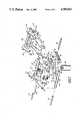
- FIG. 1is a perspective view of an adjustable office chair in accordance with the invention
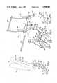
- FIG. 2is an enlarged side elevation view of the chair and showing the seat and backrest assemblies thereof in their upright positions (solid lines) and in their extreme reclining positions (broken lines);
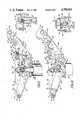
- FIG. 3is an enlarged side elevation view of the seat and backrest assemblies of the chair taken on line 3--3 of FIG. 4;
- FIG. 4is a top plan view, with portions broken away, of the seat assembly and a portion of the backrest assembly taken on line 4--4 of FIG. 3;
- FIG. 5is a side elevation view of the seat assembly taken on line 5--5 of FIG. 4 and showing the seat pan thereof in its intermediate latched position;
- FIG. 6is a view similar to FIG. 5 but taken on line 6--6 of FIG. 4 and showing the seat pan moved upwardly from its highest latched position to effect latch release;
- FIG. 7is an exploded perspective view, with certain elements omitted, of the seat assembly and a portion of the backrest assembly;
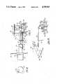
- FIG. 8is an exploded perspective view, with certain elements omitted, of the framework of the backrest assembly shown in FIGS. 3 and 4;
- FIG. 9is a side elevation view of the backrest framework of FIG. 8 and showing its most upright attitude and an alternative tilt position;
- FIG. 10is an enlarged side elevation view, partly in section, taken on line 10--10 of FIG. 4;
- FIG. 11is a view similar to FIG. 10, but taken on line 11--11 of FIG. 4;
- FIG. 12is a cross-section view taken on line 12--12 of FIG. 10;
- FIG. 13is a cross-section view taken on line 13--13 of FIG. 11;
- FIG. 14is a view similar to FIG. 10 but showing the upper seat frame of the seat assembly in a lowered position it would assume under the weight of a chair occupant and with the force adjustment mechanism adjusted to enable the springs to exert the heaviest force;
- FIG. 15is a view similar to FIG. 14 but showing the force adjustment mechanism adjusted to enable the springs to exert the lightest force;
- FIG. 16is a side elevation view, partly in cross section, of the valve control mechanism shown in top plan view in FIG. 4 and employed to enable raising and lowering the seat assembly;
- FIG. 17is an enlarged top plan view of the spring bias force adjustment mechanism shown in FIG. 4.
- FIG. 18is an end view of the operating knob of the mechanism of FIG. 17.
- FIGS. 1 and 2show an adjustable office chair 10 in accordance with the invention which comprises a base assembly 12, a seat assembly 14 and a backrest assembly 16.
- Base assembly 12comprises a plurality of radially extending legs 18 having casters 20 thereon and joined together at a central hub 22.
- a pneumatic actuator 24which is a commercially available component and is disclosed in aforementioned U.S. Pat. No. 3,711,054, is provided to adjust the height of seat assembly 14 (and backrest assembly 16 attached thereto) and comprises a cylinder 26 mounted on hub 22, a piston 23 slidably mounted in the cylinder, a vertically extending axially movable piston rod 28 connected to the piston, and a control valve 30 mounted on piston 23.
- a tubular column 32is mounted on hub 22 and surrounds actuator 24 and a sleeve 34 mounted on piston rod 28 telescopically receives column 32.
- Seat assembly 14is mounted on base assembly 12 (i.e., on piston rod 28) so that the seat assembly can be rotated in either direction in a horizontal plane by a seat occupant and so that the seat assembly can be raised and lowered vertically (arrow A, FIG. 2) relative to the base assembly to a desired height with the aid of actuator 24 when valve 30 is opened.
- the upper end of piston rod 28is tapered and sleeve 34, which telescopically receives column 32 on hub 22, is supported thereon by means of a rubber ring 36.
- the tapered end of piston rod 28extends through a collar 38 which is rigidly secured to a lower seat frame 50, hereinafter described, of seat assembly 14 and is rigidly secured to collar 38 by a taper fit.
- Piston rod 28has a passage (not shown) which extends axially therethrough and accommodates a valve stem 40 which is axially movable to operate (open and close) control valve 30 within cylinder 26.
- Actuator 24is preloaded with compressed gas so that piston rod 28 is normally biased upwardly.
- Selectively operable, normally closed control valve 30, when open,causes piston rod 28 to extend and move seat assembly 14 upward, if the chair is unoccupied. Opening valve 30 also enables seat assembly 14 and piston rod 28 to be forced downward against the force of the compressed gas under the weight of the chair occupant.
- FIGS. 4 and 16show that a manually operable valve control mechanism, including a member or lever 42 is provided for operating (opening and closing) valve 30.
- seat height adjustment lever 42is in the form of a first bell crank which is pivotally mounted by a pivot pin 43 on the underside of a seat pan 54 in seat assembly 14.
- the other arm of bell crank 42is pivotally connected to one end of an axially shiftable control rod 44.
- the other end of control rod 44is pivotally connected to one arm of a second bell crank 46 which is pivotally mounted by a pivot pin 48 to a bracket 47 which is rigidly secured as by welding to collar 38 on the framework of seat assembly 14.
- second bell crank 46carries a plate on which is secured a nut 49 and an adjustment screw 45 in nut 49 engages the end of valve stem 40 which is biased thereagainst.
- valve stem 40When valve stem 40 is raised (as shown in FIG. 16), the valve is closed and seat assembly 14 cannot be raised or lowered.
- lever 42When lever 42 is depressed (moved clockwise in FIG. 16), rod 44 shifts leftward, second bell crank 46 moves counterclockwise, stem 40 moves downward and valve 30 is opened. With the valve 30 open, seat assembly 14 can be raised or lowered to any height at or between its extreme upper and lower limits of travel.
- valve 30closes and seat assembly 14 is maintained at whatever height it is at.
- seat assembly 14comprises a seat framework including a lower seat frame 50 mounted for horizontal rotation on piston rod 28 and a movable upper seat frame 52 pivotally mounted on lower seat frame 50 for movement in the direction of arrow C (FIG. 7).
- a seat pan 54is pivotally mounted on upper seat frame 52 for pivotal movement up or down manually in the direction of arrow B (FIG. 2) to any one of a plurality of seat pan attitudes by pivot pins 55.
- FIGS. 3, 4, 5 and 6show a ratchet type latch mechanism 56 connected between upper seat frame 52 and seat pan 54 and which operates in response to manual raising or lowering of the front end of seat pan 54 to automatically releasably latch the seat pan in selected attitudes.
- a mechanism similar to mechanism 56is disclosed in detail in U.S. patent application Ser. No. 912,495, filed Sept. 29, 1986, by Kevin E. Hill for "Self-Releasing Ratchet-Type Seat Adjustment", and assigned to the same assignee as the present application.
- Seat pan 54can assume three latched positions, namely, lowest, intermediate and highest latched positions and can be moved upward from the highest latched position to release the latch and allow the seat pan to be moved down to its lowest position.
- FIG. 5shows seat pan 54 latched in its intermediate position
- FIG. 6shows the seat pan manually raised above its highest latched position to effect the release of latch mechanism 56 and enable the seat pan to be returned to its lowermost position from which it can be raised to intermediate and highest attitudes
- Latch mechanism 56generally comprises a pair of pawls 58 which are rotatably mounted on the projecting ends of rod 75.
- FIG. 4shows that the pawls are interconnected by a rigid bar 53.
- Mechanism 56also comprises a single latch plate 59 which is pivotally connected by a pin 60 to the front end of the occupant's left side plate 78 of upper seat frame 52.
- Each pawl 58is biased in a clockwise direction (relative to FIGS. 3, 5 and 6) by a biasing spring 69 shown in FIG. 4.
- Latch plate 59is provided with an opening 59A which receives a pin 61 which is connected to a side arm 62 of left side plate 78 and limits travel of latch plate 59.
- Left seat pan side arm 62carries a latch pick-up pin 63 which extends into opening 59A and operates to raise plate 59 (see FIG. 6) to thereby rotate pawl 58 counterclockwise (FIG. 6) so that seat pan 54 can be moved toward its lowest position.
- the projection 64 on pawl 58engages the upper step 65 on plate 59 (FIG. 3) and the seat pan assumes its lowest position.
- Pawl 58comprises a projection 64 which releasably engages either of two ratchet teeth 65 on latch plate 59.
- the rigid bar 53 connected to each pawl 58is releasably engageable either of two steps 67 on the end of seat pan side arm 62 and is also releasably engageable with the underside of seat 54.
- Seat pan 54can be raised from its lowest latched position to the intermediate latched position, and to its highest latched position.
- projection 64 of pawl 58is caused to drop down from higher step 65 (FIG. 5) to lower step 65 (FIG. 6).
- lower seat frame 50comprises a center plate 70 on which collar 38 is rigidly mounted.
- a pair of laterally spaced apart side arms 72are rigidly secured as by welding to center plate 70.
- a plate 73is welded between the side arms 72 below center plate 70.
- a front tube 74is rigidly secured as by welding to the front ends of the side arms 72.
- Tube 74accommodates a rod 75 on which upper seat frame 52 is pivotally mounted.
- One end of each of a pair of helical tension type biasing springs 76are anchored to the projecting ends of tube 74.
- Upper seat frame 52comprises a pair of laterally spaced apart side arms 78 which are rigidly secured as by welding at their rear ends to a rear tube 80.
- the side arms 78have holes 82 which pivotally receive the projecting ends of rod 75 so that upper seat frame 52 can pivot up or down on rod 75 in the direction of arrow C (FIG. 7) relative to lower seat frame 50 between a nominal level (0°) position and a maximum downwardly and rearwardly sloped position wherein it is displaced an angular distance of about 10° (compare the two positions of tube 80 in FIG. 14).
- Upper seat frame 52pivots or slopes downwardly a few degrees (about 3°) under the weight of the chair occupant but slopes downwardly even further (up to the maximum of 10°) when backrest assembly 16 is subjected to a rearward reclining force by the occupant (up to a maximum of 18°), as will hereinafter appear.
- each biasing spring 76is anchored to tube 74.
- the rear end of each spring 76is connected to a rotatable bushing 85 on a pin 86 which is mounted on one arm of a bell crank 87.
- Bell crank 87comprises two laterally spaced apart plates 8A which are joined by a tube 93 welded therebetween.
- Bell crank 87is pivotally mounted at the rear ends of the side arms 72 of lower seat frame 50 by means of a pivot rod 89.
- Rod 89extends through holes 90 in the arms 72 and through a hole 92 in tube 93 in bell crank 87.
- the springs 76tend to bias bell crank 87 counterclockwise (with respect to FIG. 7).
- a resilient (rubber) upstop 88 on the said one arm of bell crank 87engages plate 73 on lower seat frame 50 when the chair is unoccupied to limit upward movement of upper seat frame 52.
- the other arm of bell crank 87is connected by a movable linkage which opposes the spring bias and comprises a pair of links 94, a small crank 95, and a spring tension adjustment mechanism 97 mounted on tube 80 of upper seat frame 52.
- Mechanism 97comprises a pair of laterally spaced apart side plates 98 welded to tube 80 and a manually operable gear assembly 100, hereinafter described.
- Each link 94is pivotally connected one end to the said other arm of bell crank 87 and is pivotally connected at its other end to one arm of crank 95.
- Crank 95is pivotally mounted on the side plates 98 of mechanism 97 by means of a pin 99.
- Crank 95is adjustably pivotable on the side plates 98 by gear assembly 100 to effect repositioning of the links 94 and 95.
- Repositioning of links 95 and 94 relative to bell crank 87changes the effective moment arm and stroke of bell crank 87 thereby increasing or decreasing the spring biasing force acting on upper seat frame 52 and on backrest framework of backrest assembly 16 without changing the initial preloading of the springs 76, thereby reducing the force required to adjust the spring biasing.
- a resilient (rubber) downstop 101 on a crossmember 98A rigidly secured between the side plates 98engages the bell crank tube 93 to limit maximum downward pivoting movement of upper seat frame 52.
- gear assembly 100comprises a rotatable threaded adjustment screw 102 which threadedly engages a threaded hole 104 in an upper bevel gear 110 hereafter described.
- Screw 102has an eye 103 at its end which receives a small pin 106 which is fixedly mounted in the holes 108 in the said other arm of crank 95.
- First or upper bevel gear 110is rotatably mounted on an end plate 111 which is rigidly affixed to the side plates 98.
- Bevel gear 110meshes with a second bevel gear 112 which is rigidly affixed to the inner end of a rotatable rod 114.
- Rod 114is rotatably mounted in a hole 116 in one of the side arms 78 of upper seat frame 52 and has a knob 118 at its outer end whereby manual rotation of rod 114 is effected to adjust effective spring biasing force.
- FIGS. 14 and 15show the position of the links 94, crank 95 and a bell crank 87 when adjustment screw 102 of spring bias force adjustment mechanism 97 is in lightest and heaviest force positions, respectively.
- FIGS. 10 and 11also show these components in heaviest force position.
- backrest assembly 16comprises a backrest framework including a lower backrest frame 120 and an upper backrest frame 122.
- Lower backrest frame 120comprises a pair of laterally spaced apart side plates 124 which are rigidly secured together by a pair of rigid tubular members 126 and 128 which are welded between the side plates 124 and have outwardly projecting ends.
- Each side plate 124is provided with a hole 130 which enables lower backrest frame 120 to be pivotally connected, as by a pivot rod 132, to tube 80 of upper seat frame 52.
- Lower backrest frame 120further comprises a pair of laterally spaced apart downwardly depending members or legs 134 which are rigidly secured as by welding to tubular member 126.
- Each leg 134is provided with an elongated slot 136 which slidably and pivotably receives and engages the ends of pivot pin 89 of bell crank 87.
- the foregoing arrangementenables lower backrest frame 120 to incline or tilt rearwardly in the direction of arrow D (FIG. 2) and the upper seat frame 52 to slope downwardly and rearwardly in the direction of arrow C (FIG. 7), both moving at proportional rates and against spring bias under the force imposed by the chair occupant.
- meansare provided for enabling and controlling reclining motion of chair 10 and operate to bias upper seat frame 52 (and seat pan 54 mounted thereon) and lower backrest frame 120 (and upper backrest frame 122 mounted thereon) to an upright position when the chair is unoccupied.
- These meansalso enable the chair occupant to force the backrest assembly (comprising backrest frames 120 and 122) and upper seat frame 52 to a reclining position against spring bias as the occupant leans backward.
- the backrest assembly (frames 120 and 122) and upper seat frame 52move angularly simultaneously and at different but proportional rates relative to each other.
- upper seat frame 52can move between 0° (level) and a maximum 10° downward slope relative to rigid lower seat frame 50, whereas lower backrest frame 120 (and upper backrest frame 122 affixed thereto) can move between 0° (upright) and a maximum 18° rearward tilt position relative to rigid lower seat frame 50 and thus moves in proportion to the angular movement of upper seat frame 52.
- the means for enabling and controlling such reclining motioninclude previously described bell crank 87 pivotally mounted on the rear of lower seat frame 50, the biasing springs 76 connected between the front end of lower seat frame 50 and one arm of bell crank 87, the movable linkage connected between the other arm of bell crank 87 and the rear end of upper seat frame 52, and the means for slidably and pivotally connecting downwardly depending member or leg 134 on lower backrest frame 120 (which lower backrest frame 120 is pivotally connected to the rear of upper seat frame 52) to lower seat frame 50 at or near the pivot point 90 of bell crank 87.
- Spring biasis thus transmitted from springs 76, through bell crank 87 and through the movable linkage to upper seat frame 52 and from there to lower backrest frame 120.
- the depending members or legs 134effect simultaneous proportional angular reclining movement of upper seat frame 52 and lower backrest frame 120.
- upper backrest frame 122is mounted for pivotal movement fore and aft in the direction of arrow E (FIG. 9) to various attitudes relative to lower backrest frame 120.
- Upper backrest frame 122comprises a pair of laterally spaced apart side members 140 which are rigidly secured together by a pair of rigid tubular members 141 and 142 which are welded therebetween.
- Each side member 140is provided with a hole 144 for receiving a pivot rod 146 which also extends through holes 148 in the side plates 124 of lower backrest frame 120 and serves to pivotally connect the frames 120 and 122 together.
- a small helical biasing spring 150is disposed on rod 146 and is connected between the upper and lower backrest frames 122 and 120 for biasing upper backrest frame 122 forwardly toward upright position and against a rod 152 of a backrest tilt locking mechanism 156.
- One end of spring 150engages tube 141 on upper seat frame 122 and the other end of spring 150 engages a hole 149 in side plate 124 of lower backrest frame 120.
- Rod 152moves in the direction of arrow G (FIG. 8) in response to manual movement of upper backrest frame 122.
- Backrest tilt locking mechanism 156which is a commercially available component, is selectively operable to releasably lock upper backrest frame 122 in any position into which it is moved relative to lower backrest frame 120.
- Mechanism 156comprises a housing 158 connected by a pivot pin 160 between a side plate 124 of lower backrest frame 120 and a rigid support arm 125 welded on an end of tube 126.
- the axis of pivot pin 160is displaced downwardly from the axis of pivot rod 146.
- the adjustably movable (extendable and retractable) rod 152extends from housing 158 and is connected to the relatively movable upper backrest frame 122 by a pin 164.
- a manually operable locking mechanismincluding a rotatable rod 166 to which a manually operable lever 167 is affixed, is mounted on housing 158 and is connected to lock or unlock rod 152 so that it can be extended or retracted in response to manual tilting movement of upper backrest frame 122 relative, to lower backrest frame 120 (see FIG. 9) to desired tilt positions.
- lever 167which is internally biased into locked position by means (not shown) within housing 158, is manually moved to unlocked position, upper backrest frame 122 can be tilted.
- a lockout mechanism 170is provided to selectively prevent or permit reclining motion of backrest assembly 16 and upper seat frame 52 of seat assembly 14.
- Mechanism 170comprises a movable lockout plate 171 and a manually operable control rod 172 therefor.
- Lockout plate 171has one end movably engaged by entrapment between two projections 174 on tube 80 of upper seat frame 52 and has its other end selectively movable into and out of engagement with bell crank 87 by means of the manually operable axially movable rod 172 which is slidably mounted in a hole 176 in side member 78 of upper seat frame 52.
- lockout plate 171engages bell crank rotation in response to downward force imposed on seat assembly 14 or in response to attempted reclining motion of backrest assembly 16.
- axial movement of rod 172is effected by axial movement of a cylinder cam 176 which is fixedly mounted on the outer end of rod 172.
- Cylinder cam 176is provided with a helical cam slot 177 therein which slidably engages a cam follower projection 178.
- Projection 178extends outwardly from a sleeve 179 which is rotatably mounted on knob 118 which is rigidly secured to rotatable rod 114.
- Cylinder cam 176 and rod 172move axially when sleeve 179 is rotated by lever 180.
- Sleeve 179 and the attached lever 180can to be rotated 90° in the direction of arrow H (FIG. 18) between two positions so as to cause rod 172 to move axially toward and away from bell crank 87 and effect corresponding movement of the lower end of lockout plate 171.
- a helical compression spring 183is disposed on rod 172 between left side plate 78 of upper seat frame 52 and a flange 185 on rod 172. Spring 183 biases rod 172, lockout plate and knob 179 toward lockout position.
- the manual controls for adjusting height adjustment, seat pan attitude, backrest tilt, spring force adjustment and lockoutare located on seat assembly 14 so as to be conveniently accessible to the chair occupant. More specifically, as FIGS. 1 and 2 show, the exterior of chair 10 is provided with rigid plastic or fiberglass shell-like covers or panels which are rigidly secured to portions of the seat framework and to the backrest framework, along with suitable upholstery panels to conceal the framework and associated mechanisms, to prevent the occupant's clothing from catching on projections, and for aesthetic purposes.
- seat assembly 14is provided with a panel having two panel sides 200 and 201 (see FIG. 4) on opposite lateral sides thereof which are understood to be rigidly secured to and movable with movable upper seat frame 52 by attachment means (not shown).
- Seat assembly 14is also provided with a flexible upholstery panel 204 which is attached to seat pan 54.
- Panel 200 on the occupant's left side of seat assembly 14is provided with an access hole 206 (FIGS. 1, 2 and 4) through which projects rotatable lever 167 for backrest tilt locking.
- Panel 201 on the occupant's right side of seat assembly 14is provided with an access hole 208 (FIG. 4) through which projects vertically movable lever 42 for seat height adjustment.
- Panel 201is also provided with an access hole 210 (FIG. 4) through which projects rotatable knob 118 for tension adjustment and rotatable lever 180 for lockout of reclining motion.
Landscapes
- Health & Medical Sciences (AREA)
- Dentistry (AREA)
- General Health & Medical Sciences (AREA)
- Chairs Characterized By Structure (AREA)
- Chairs For Special Purposes, Such As Reclining Chairs (AREA)
Abstract
Description
Claims (22)
Priority Applications (1)
| Application Number | Priority Date | Filing Date | Title |
|---|---|---|---|
| US06/940,953US4709963A (en) | 1986-12-12 | 1986-12-12 | Adjustable office chair |
Applications Claiming Priority (1)
| Application Number | Priority Date | Filing Date | Title |
|---|---|---|---|
| US06/940,953US4709963A (en) | 1986-12-12 | 1986-12-12 | Adjustable office chair |
Publications (1)
| Publication Number | Publication Date |
|---|---|
| US4709963Atrue US4709963A (en) | 1987-12-01 |
Family
ID=25475705
Family Applications (1)
| Application Number | Title | Priority Date | Filing Date |
|---|---|---|---|
| US06/940,953Expired - Fee RelatedUS4709963A (en) | 1986-12-12 | 1986-12-12 | Adjustable office chair |
Country Status (1)
| Country | Link |
|---|---|
| US (1) | US4709963A (en) |
Cited By (75)
| Publication number | Priority date | Publication date | Assignee | Title |
|---|---|---|---|---|
| US4834453A (en)* | 1986-09-08 | 1989-05-30 | Girsberger Holding Ag | Swivel chair |
| US4848837A (en)* | 1986-10-15 | 1989-07-18 | Voelkle Rolf | Chair having a pelvis-hip support adjustable relative to a front seat portion |
| US5029940A (en)* | 1990-01-16 | 1991-07-09 | Westinghouse Electric Corporation | Chair tilt and chair height control apparatus |
| US5035467A (en)* | 1988-09-15 | 1991-07-30 | Pin Dot Products | Seating system |
| US5106157A (en)* | 1989-03-01 | 1992-04-21 | Herman Miller, Inc. | Chair height and tilt adjustment mechanisms |
| EP0512194A1 (en)* | 1991-05-08 | 1992-11-11 | SIFA Sitzfabrik GmbH | Tilt adjustment device for seats, in particular rotatable office chairs |
| US5423594A (en)* | 1991-05-21 | 1995-06-13 | Ashfield Engineering Company Wexford Limited | Chair tilting mechanism |
| US5476306A (en)* | 1994-01-13 | 1995-12-19 | Westinghouse Electric Corporation | Chair back support adjustment mechanism |
| US5538326A (en)* | 1994-11-14 | 1996-07-23 | Milsco Manufacturing Company | Flexible unitary seat shell |
| WO1996025071A1 (en)* | 1995-02-17 | 1996-08-22 | Steelcase Inc. | Modular chair construction and method of assembly |
| US5568961A (en)* | 1994-08-10 | 1996-10-29 | Findlay Industries | Tubular seat frame |
| US5577807A (en) | 1994-06-09 | 1996-11-26 | Steelcase Inc. | Adjustable chair actuator |
| US5584533A (en)* | 1993-04-14 | 1996-12-17 | Mauser Waldeck Ag | Chair with variable inclination of the seat and backrest |
| US5658045A (en)* | 1994-10-11 | 1997-08-19 | Kusch & Co. Sitzmobelwerke Kg | Chair with adjustable seat and backrest |
| US5725276A (en)* | 1995-06-07 | 1998-03-10 | Ginat; Jonathan | Tilt back chair and control |
| USD396976S (en) | 1997-04-07 | 1998-08-18 | Steelcase Inc. | Chair |
| US6003943A (en)* | 1996-04-22 | 1999-12-21 | Steelcase Development Inc. | Multi-function control for chair |
| US6007150A (en)* | 1998-03-08 | 1999-12-28 | Milsco Manufacturing Company | Motorcycle seat with adjustable backrest |
| GB2340746A (en)* | 1998-07-27 | 2000-03-01 | Ashfield Eng Co Wexford Ltd | Posture-responsive chair |
| US6086153A (en)* | 1997-10-24 | 2000-07-11 | Steelcase Inc. | Chair with reclineable back and adjustable energy mechanism |
| US6224155B1 (en) | 1999-01-12 | 2001-05-01 | Steelcase Development Inc. | Vertical height adjustment mechanism for chairs |
| US6234573B1 (en) | 1998-05-27 | 2001-05-22 | Peter Röder | Chair, in particular office chair |
| US6250715B1 (en) | 1998-01-21 | 2001-06-26 | Herman Miller, Inc. | Chair |
| US20020179131A1 (en)* | 2001-06-01 | 2002-12-05 | The Regents Of The University Of Minnesota | Tray apparatus and methods regarding same |
| US6582019B2 (en) | 2000-03-17 | 2003-06-24 | Herman Miller, Inc. | Tilt assembly for a chair |
| US20040000805A1 (en)* | 2000-05-22 | 2004-01-01 | Herman Miller, Inc. | Office chair |
| US20040135413A1 (en)* | 2002-01-08 | 2004-07-15 | Dauphin Entqicklungs- U. Beteiligungs-Gmbh | Chair |
| US20040144906A1 (en)* | 2002-11-15 | 2004-07-29 | Milsco Manufacturing, A Unit Of Jason Inc. | Vehicle seat suspension and method |
| US20040174059A1 (en)* | 2003-03-07 | 2004-09-09 | Dauphin Entwicklungs-U. Beteiligungs Gmbh | Chair, in particular office chair |
| US6820935B1 (en)* | 2000-10-18 | 2004-11-23 | Enrico Cioncada | Armchair with variable position |
| US20050029849A1 (en)* | 2003-06-23 | 2005-02-10 | Goetz Mark W. | Tilt chair |
| US6880886B2 (en) | 2002-09-12 | 2005-04-19 | Steelcase Development Corporation | Combined tension and back stop function for seating unit |
| US20050121276A1 (en)* | 2003-12-04 | 2005-06-09 | Tsann Kuen Enterprise Co., Ltd. | Electrical appliance having a wire winding device |
| US20050275269A1 (en)* | 2004-05-14 | 2005-12-15 | Tim Fookes | Tilt tension mechanism for chair |
| USD516327S1 (en) | 2003-10-17 | 2006-03-07 | Milsco Manufacturing, A Unit Of Jason Incorporated | Vehicle seat |
| US7065809B1 (en) | 2003-05-07 | 2006-06-27 | Milsco Manufacturing Company | Recessed cushion ornament |
| US20070001497A1 (en)* | 2005-06-20 | 2007-01-04 | Humanscale Corporation | Seating apparatus with reclining movement |
| US20070057553A1 (en)* | 2005-03-01 | 2007-03-15 | Roslund Richard N | Tilt control mechanism for a chair |
| US20070108819A1 (en)* | 2005-11-11 | 2007-05-17 | Kokuyo Furniture Co., Ltd. | Chair |
| US20070108831A1 (en)* | 2005-11-11 | 2007-05-17 | Kokuyo Furniture Co., Ltd. | Structure for connecting members |
| US20070108822A1 (en)* | 2005-11-11 | 2007-05-17 | Kokuyo Furniture Co., Ltd. | Chair |
| US20070108821A1 (en)* | 2005-11-11 | 2007-05-17 | Kokuyo Furniture Co.,Ltd. | Chair |
| US20070108818A1 (en)* | 2005-11-11 | 2007-05-17 | Kokuyo Furniture Co., Ltd. | Structure for attaching spring |
| US7237841B2 (en) | 2004-06-10 | 2007-07-03 | Steelcase Development Corporation | Back construction with flexible lumbar |
| WO2007148923A1 (en)* | 2006-06-22 | 2007-12-27 | Man Plus Co Ltd | Chair with automatically movable back support |
| US20080111414A1 (en)* | 2006-10-13 | 2008-05-15 | L&P Property Management Company | Casual control tilt lockout |
| WO2008073028A1 (en)* | 2006-12-15 | 2008-06-19 | Scania Cv Ab (Publ) | Vehicle seat comprising fully similtaneous adjustment |
| US7458637B2 (en) | 2004-06-10 | 2008-12-02 | Steelcase Inc. | Back construction with flexible lumbar |
| US20090079238A1 (en)* | 2007-09-20 | 2009-03-26 | Claudia Plikat | Body support structure |
| US20090261637A1 (en)* | 2006-03-24 | 2009-10-22 | Johann Burkhard Schmitz | Piece of Furniture |
| US20100133413A1 (en)* | 2008-12-01 | 2010-06-03 | Wahls Robert J | Adjustable Vehicle Seat Suspension |
| US20100187881A1 (en)* | 2007-05-22 | 2010-07-29 | Delta Tooling Co., Ltd | Seat structure |
| US20100219672A1 (en)* | 2006-01-23 | 2010-09-02 | Donati, S.p.A. | Device for adjusting the tilt of a backrest or seat of a chair |
| US20110101750A1 (en)* | 2009-11-02 | 2011-05-05 | B/E Aerospace. Inc. | Seat pan drop down link |
| US20110210593A1 (en)* | 2010-02-26 | 2011-09-01 | Zero1 | Chair with collapsible seat back |
| US20110233983A1 (en)* | 2010-03-27 | 2011-09-29 | Shunjie Lu | Chair with back-and-forth moving backrest |
| USD660056S1 (en) | 2006-06-20 | 2012-05-22 | Humanscale Corporation | Chair |
| US8240771B2 (en) | 2004-05-13 | 2012-08-14 | Humanscale Corporation | Mesh chair component |
| US8262162B2 (en) | 2007-01-29 | 2012-09-11 | Herman Miller, Inc. | Biasing mechanism for a seating structure and methods for the use thereof |
| USD673401S1 (en) | 2005-05-13 | 2013-01-01 | Humanscale Corporation | Chair support structure |
| US20140077551A1 (en)* | 2012-09-20 | 2014-03-20 | Steelcase Inc. | Chair Assembly |
| US20150164225A1 (en)* | 2012-03-08 | 2015-06-18 | Walter Knoll Ag & Co. Kg | Functional Chair |
| US9352675B2 (en) | 2011-09-21 | 2016-05-31 | Herman Miller, Inc. | Bi-level headrest, body support structure and method of supporting a user's cranium |
| US9504326B1 (en) | 2012-04-10 | 2016-11-29 | Humanscale Corporation | Reclining chair |
| US10130184B2 (en)* | 2016-10-07 | 2018-11-20 | Pao Shen Enterprises Co., Ltd. | Adjusting mechanism and chair including the same |
| USD853163S1 (en)* | 2017-05-15 | 2019-07-09 | Bock 1 Gmbh & Co. Kg | Office chair |
| US10624457B2 (en)* | 2016-03-14 | 2020-04-21 | Herman Miller, Inc. | Chair |
| US10966531B2 (en) | 2018-01-25 | 2021-04-06 | David James France | Ergonomic chair |
| US11096492B2 (en)* | 2017-10-06 | 2021-08-24 | Co.Fe.Mo. Industrie S.R.L. | Oscillation system for chairs |
| US11109683B2 (en) | 2019-02-21 | 2021-09-07 | Steelcase Inc. | Body support assembly and method for the use and assembly thereof |
| EP3613313B1 (en)* | 2018-08-20 | 2022-03-23 | RECARO Gaming GmbH & Co. KG | E-gaming seat |
| US20220087425A1 (en)* | 2020-09-18 | 2022-03-24 | Dinkar Chellaram | Synchronous-tilt reclining chair |
| US11304528B2 (en) | 2012-09-20 | 2022-04-19 | Steelcase Inc. | Chair assembly with upholstery covering |
| US11357329B2 (en) | 2019-12-13 | 2022-06-14 | Steelcase Inc. | Body support assembly and methods for the use and assembly thereof |
| US20230043045A1 (en)* | 2020-04-09 | 2023-02-09 | Jongsung HWANG | Chair for reducing load on buttocks and waist |
Citations (4)
| Publication number | Priority date | Publication date | Assignee | Title |
|---|---|---|---|---|
| US2784767A (en)* | 1955-04-28 | 1957-03-12 | Manton Ahlberg H | Control for tilting seat and back of posture chairs |
| US3622202A (en)* | 1969-07-07 | 1971-11-23 | Vernon C Brown | Adjustable chair and control therefor |
| US4509793A (en)* | 1982-09-03 | 1985-04-09 | Wilkhahn Wilening + Hahne GmbH + Co. | Chair |
| US4652050A (en)* | 1984-01-11 | 1987-03-24 | Herman Miller, Inc. | Chair tilt mechanism |
- 1986
- 1986-12-12USUS06/940,953patent/US4709963A/ennot_activeExpired - Fee Related
Patent Citations (4)
| Publication number | Priority date | Publication date | Assignee | Title |
|---|---|---|---|---|
| US2784767A (en)* | 1955-04-28 | 1957-03-12 | Manton Ahlberg H | Control for tilting seat and back of posture chairs |
| US3622202A (en)* | 1969-07-07 | 1971-11-23 | Vernon C Brown | Adjustable chair and control therefor |
| US4509793A (en)* | 1982-09-03 | 1985-04-09 | Wilkhahn Wilening + Hahne GmbH + Co. | Chair |
| US4652050A (en)* | 1984-01-11 | 1987-03-24 | Herman Miller, Inc. | Chair tilt mechanism |
Cited By (169)
| Publication number | Priority date | Publication date | Assignee | Title |
|---|---|---|---|---|
| US4834453A (en)* | 1986-09-08 | 1989-05-30 | Girsberger Holding Ag | Swivel chair |
| US4848837A (en)* | 1986-10-15 | 1989-07-18 | Voelkle Rolf | Chair having a pelvis-hip support adjustable relative to a front seat portion |
| US5035467A (en)* | 1988-09-15 | 1991-07-30 | Pin Dot Products | Seating system |
| US5106157A (en)* | 1989-03-01 | 1992-04-21 | Herman Miller, Inc. | Chair height and tilt adjustment mechanisms |
| US5192114A (en)* | 1989-03-01 | 1993-03-09 | Herman Miller, Inc. | Tilt adjustment control for a chair |
| US5244253A (en)* | 1989-03-01 | 1993-09-14 | Herman Miller, Inc. | Height adjustment control for a chair |
| US5029940A (en)* | 1990-01-16 | 1991-07-09 | Westinghouse Electric Corporation | Chair tilt and chair height control apparatus |
| EP0512194A1 (en)* | 1991-05-08 | 1992-11-11 | SIFA Sitzfabrik GmbH | Tilt adjustment device for seats, in particular rotatable office chairs |
| US5423594A (en)* | 1991-05-21 | 1995-06-13 | Ashfield Engineering Company Wexford Limited | Chair tilting mechanism |
| US5584533A (en)* | 1993-04-14 | 1996-12-17 | Mauser Waldeck Ag | Chair with variable inclination of the seat and backrest |
| US5476306A (en)* | 1994-01-13 | 1995-12-19 | Westinghouse Electric Corporation | Chair back support adjustment mechanism |
| US5577807A (en) | 1994-06-09 | 1996-11-26 | Steelcase Inc. | Adjustable chair actuator |
| US5568961A (en)* | 1994-08-10 | 1996-10-29 | Findlay Industries | Tubular seat frame |
| US5658045A (en)* | 1994-10-11 | 1997-08-19 | Kusch & Co. Sitzmobelwerke Kg | Chair with adjustable seat and backrest |
| US5538326A (en)* | 1994-11-14 | 1996-07-23 | Milsco Manufacturing Company | Flexible unitary seat shell |
| US5599069A (en)* | 1994-11-14 | 1997-02-04 | Milsco Manufacturing Company | Flexible unitary seat shell including base section having frame sockets |
| US5979988A (en)* | 1995-02-17 | 1999-11-09 | Steelcase Development Inc. | Modular chair construction and method of assembly |
| US5782536A (en)* | 1995-02-17 | 1998-07-21 | Steelcase Inc. | Modular chair construction and method of assembly |
| US5873634A (en)* | 1995-02-17 | 1999-02-23 | Steelcase Inc. | Modular chair construction and method of assembly |
| WO1996025071A1 (en)* | 1995-02-17 | 1996-08-22 | Steelcase Inc. | Modular chair construction and method of assembly |
| US5630647A (en)* | 1995-02-17 | 1997-05-20 | Steelcase Inc. | Tension adjustment mechanism for chairs |
| US6039397A (en)* | 1995-06-07 | 2000-03-21 | Ginat; Jonathan | Tilt back chair control |
| US5725276A (en)* | 1995-06-07 | 1998-03-10 | Ginat; Jonathan | Tilt back chair and control |
| US6003943A (en)* | 1996-04-22 | 1999-12-21 | Steelcase Development Inc. | Multi-function control for chair |
| USD396976S (en) | 1997-04-07 | 1998-08-18 | Steelcase Inc. | Chair |
| US7040711B2 (en) | 1997-10-24 | 2006-05-09 | Steelcase Development Corporation | Nonslip bearing arrangement |
| US6394549B1 (en) | 1997-10-24 | 2002-05-28 | Steelcase Development Corporation | Seating unit with reclineable back and forwardly movable seat |
| US6086153A (en)* | 1997-10-24 | 2000-07-11 | Steelcase Inc. | Chair with reclineable back and adjustable energy mechanism |
| US6116695A (en)* | 1997-10-24 | 2000-09-12 | Steelcase Development Inc. | Chair control having an adjustable energy mechanism |
| US7040709B2 (en) | 1997-10-24 | 2006-05-09 | Steelcase Development Corporation | Back construction for seating unit having inverted U-shaped frame |
| US7114777B2 (en) | 1997-10-24 | 2006-10-03 | Steelcase Development Corporation | Chair having reclineable back and movable seat |
| US6991291B2 (en) | 1997-10-24 | 2006-01-31 | Steelcase Development Corporation | Back construction for seating unit having spring bias |
| US7131700B2 (en) | 1997-10-24 | 2006-11-07 | Steelcase Development Corporation | Back construction for seating unit |
| US6817668B2 (en) | 1997-10-24 | 2004-11-16 | Steelcase Development Corporation | Seating unit with variable back stop and seat bias |
| US7427105B2 (en) | 1997-10-24 | 2008-09-23 | Steelcase Inc. | Back construction for seating unit |
| US6250715B1 (en) | 1998-01-21 | 2001-06-26 | Herman Miller, Inc. | Chair |
| US6386636B2 (en) | 1998-01-21 | 2002-05-14 | Herman Miller, Inc. | Chair |
| US6367876B2 (en) | 1998-01-21 | 2002-04-09 | Herman Miller, Inc. | Chair |
| US6598937B2 (en) | 1998-01-21 | 2003-07-29 | Herman Miller, Inc. | Adjustable backrest |
| US7004543B2 (en) | 1998-01-21 | 2006-02-28 | Herman Miller, Inc. | Chair |
| US6007150A (en)* | 1998-03-08 | 1999-12-28 | Milsco Manufacturing Company | Motorcycle seat with adjustable backrest |
| US6234573B1 (en) | 1998-05-27 | 2001-05-22 | Peter Röder | Chair, in particular office chair |
| US6422649B2 (en) | 1998-07-27 | 2002-07-23 | Ashfield Engineering Company Wexford Limited | Chair |
| GB2340746B (en)* | 1998-07-27 | 2002-02-13 | Ashfield Eng Co Wexford Ltd | A chair |
| GB2340746A (en)* | 1998-07-27 | 2000-03-01 | Ashfield Eng Co Wexford Ltd | Posture-responsive chair |
| US6224155B1 (en) | 1999-01-12 | 2001-05-01 | Steelcase Development Inc. | Vertical height adjustment mechanism for chairs |
| US6582019B2 (en) | 2000-03-17 | 2003-06-24 | Herman Miller, Inc. | Tilt assembly for a chair |
| US20040000805A1 (en)* | 2000-05-22 | 2004-01-01 | Herman Miller, Inc. | Office chair |
| US6758523B2 (en) | 2000-05-22 | 2004-07-06 | Herman Miller, Inc. | Office chair |
| US6820935B1 (en)* | 2000-10-18 | 2004-11-23 | Enrico Cioncada | Armchair with variable position |
| US20020179131A1 (en)* | 2001-06-01 | 2002-12-05 | The Regents Of The University Of Minnesota | Tray apparatus and methods regarding same |
| US6863346B2 (en)* | 2002-01-08 | 2005-03-08 | Dauphin Entwicklungs-U. Beteiligungs-Gmbh | Chair |
| US20040135413A1 (en)* | 2002-01-08 | 2004-07-15 | Dauphin Entqicklungs- U. Beteiligungs-Gmbh | Chair |
| US6880886B2 (en) | 2002-09-12 | 2005-04-19 | Steelcase Development Corporation | Combined tension and back stop function for seating unit |
| US7165811B2 (en) | 2002-09-12 | 2007-01-23 | Steelcase Development Corporation | Control mechanism for seating unit |
| US20040144906A1 (en)* | 2002-11-15 | 2004-07-29 | Milsco Manufacturing, A Unit Of Jason Inc. | Vehicle seat suspension and method |
| US7185867B2 (en) | 2002-11-15 | 2007-03-06 | Milsco Manufacturing Company, A Unit Of Jason Incorporated | Vehicle seat suspension and method |
| US20040174057A1 (en)* | 2003-03-07 | 2004-09-09 | Dauphin Entwicklungs-U. Beteiligungs Gmbh | Chair, in particular office chair |
| US7036882B2 (en)* | 2003-03-07 | 2006-05-02 | Dauphin Entwicklings-U. Beteiligungs Gmbh | Chair, in particular office chair |
| US20040174059A1 (en)* | 2003-03-07 | 2004-09-09 | Dauphin Entwicklungs-U. Beteiligungs Gmbh | Chair, in particular office chair |
| US6945603B2 (en)* | 2003-03-07 | 2005-09-20 | Dauphin Entwicklungs-U. Beteiligungs Gmbh | Chair, in particular office chair |
| US7065809B1 (en) | 2003-05-07 | 2006-06-27 | Milsco Manufacturing Company | Recessed cushion ornament |
| US20050029849A1 (en)* | 2003-06-23 | 2005-02-10 | Goetz Mark W. | Tilt chair |
| US7207629B2 (en) | 2003-06-23 | 2007-04-24 | Herman Miller, Inc. | Tilt chair |
| USD516327S1 (en) | 2003-10-17 | 2006-03-07 | Milsco Manufacturing, A Unit Of Jason Incorporated | Vehicle seat |
| US20050121276A1 (en)* | 2003-12-04 | 2005-06-09 | Tsann Kuen Enterprise Co., Ltd. | Electrical appliance having a wire winding device |
| US8240771B2 (en) | 2004-05-13 | 2012-08-14 | Humanscale Corporation | Mesh chair component |
| US20050275269A1 (en)* | 2004-05-14 | 2005-12-15 | Tim Fookes | Tilt tension mechanism for chair |
| US7500718B2 (en)* | 2004-05-14 | 2009-03-10 | Haworth, Inc. | Tilt tension mechanism for chair |
| US7237841B2 (en) | 2004-06-10 | 2007-07-03 | Steelcase Development Corporation | Back construction with flexible lumbar |
| US7458637B2 (en) | 2004-06-10 | 2008-12-02 | Steelcase Inc. | Back construction with flexible lumbar |
| US20110012395A1 (en)* | 2005-03-01 | 2011-01-20 | Haworth, Inc. | Tilt control mechanism for a chair |
| US7735923B2 (en) | 2005-03-01 | 2010-06-15 | Haworth, Inc. | Tilt control mechanism for a chair |
| US20090179473A1 (en)* | 2005-03-01 | 2009-07-16 | Roslund Richard N | Tilt control mechanism for a chair |
| US7997652B2 (en)* | 2005-03-01 | 2011-08-16 | Haworth, Inc. | Tilt control mechanism for a chair |
| US7429081B2 (en) | 2005-03-01 | 2008-09-30 | Haworth, Inc. | Tilt control mechanism for a chair |
| US20070057553A1 (en)* | 2005-03-01 | 2007-03-15 | Roslund Richard N | Tilt control mechanism for a chair |
| USD673401S1 (en) | 2005-05-13 | 2013-01-01 | Humanscale Corporation | Chair support structure |
| US20090152930A1 (en)* | 2005-06-20 | 2009-06-18 | Humanscale Corporation | Seating Apparatus With Reclining Movement |
| US8061775B2 (en) | 2005-06-20 | 2011-11-22 | Humanscale Corporation | Seating apparatus with reclining movement |
| US8777312B2 (en) | 2005-06-20 | 2014-07-15 | Humanscale Corporation | Seating apparatus with reclining movement |
| US20070001497A1 (en)* | 2005-06-20 | 2007-01-04 | Humanscale Corporation | Seating apparatus with reclining movement |
| US7717513B2 (en) | 2005-11-11 | 2010-05-18 | Kokuyo Furniture Co., Ltd. | Chair |
| US20070108821A1 (en)* | 2005-11-11 | 2007-05-17 | Kokuyo Furniture Co.,Ltd. | Chair |
| US20070108818A1 (en)* | 2005-11-11 | 2007-05-17 | Kokuyo Furniture Co., Ltd. | Structure for attaching spring |
| US20070108822A1 (en)* | 2005-11-11 | 2007-05-17 | Kokuyo Furniture Co., Ltd. | Chair |
| US7665805B2 (en) | 2005-11-11 | 2010-02-23 | Kokuyo Furniture Co., Ltd. | Chair |
| US7712833B2 (en) | 2005-11-11 | 2010-05-11 | Kokuyo Furniture Co., Ltd. | Structure for connecting members |
| US20100117422A1 (en)* | 2005-11-11 | 2010-05-13 | Kokuyo Furniture Co., Ltd | Structure for connecting members |
| US7434879B2 (en)* | 2005-11-11 | 2008-10-14 | Kokuyo Furniture Co., Ltd. | Structure for attaching spring |
| US7862120B2 (en) | 2005-11-11 | 2011-01-04 | Kokuyo Furniture Co., Ltd. | Chair |
| US20070108819A1 (en)* | 2005-11-11 | 2007-05-17 | Kokuyo Furniture Co., Ltd. | Chair |
| US7857389B2 (en) | 2005-11-11 | 2010-12-28 | Kokuyo Furniture Co., Ltd | Structure for connecting members |
| US20070108831A1 (en)* | 2005-11-11 | 2007-05-17 | Kokuyo Furniture Co., Ltd. | Structure for connecting members |
| US20100219672A1 (en)* | 2006-01-23 | 2010-09-02 | Donati, S.p.A. | Device for adjusting the tilt of a backrest or seat of a chair |
| US7857390B2 (en) | 2006-03-24 | 2010-12-28 | Herman Miller, Inc. | Piece of furniture |
| US8025334B2 (en)* | 2006-03-24 | 2011-09-27 | Herman Miller, Inc. | Piece of furniture |
| US20090261637A1 (en)* | 2006-03-24 | 2009-10-22 | Johann Burkhard Schmitz | Piece of Furniture |
| US20110067931A1 (en)* | 2006-03-24 | 2011-03-24 | Johann Burkhard Schmitz | Piece of furniture |
| USD661135S1 (en) | 2006-06-20 | 2012-06-05 | Humanscale Corporation | Pair of armrests for a chair or the like |
| USD660056S1 (en) | 2006-06-20 | 2012-05-22 | Humanscale Corporation | Chair |
| US20100237674A1 (en)* | 2006-06-22 | 2010-09-23 | Jong Ho Lee | Chair with automatically movable back support |
| WO2007148923A1 (en)* | 2006-06-22 | 2007-12-27 | Man Plus Co Ltd | Chair with automatically movable back support |
| US7753447B2 (en) | 2006-10-13 | 2010-07-13 | L&P Property Management Company | Casual control tilt lockout |
| US20080111414A1 (en)* | 2006-10-13 | 2008-05-15 | L&P Property Management Company | Casual control tilt lockout |
| DE112007003011B4 (en) | 2006-12-15 | 2017-11-02 | Scania Cv Ab (Publ) | Vehicle seat with a completely simultaneous adjustment |
| WO2008073028A1 (en)* | 2006-12-15 | 2008-06-19 | Scania Cv Ab (Publ) | Vehicle seat comprising fully similtaneous adjustment |
| US8262162B2 (en) | 2007-01-29 | 2012-09-11 | Herman Miller, Inc. | Biasing mechanism for a seating structure and methods for the use thereof |
| US20100187881A1 (en)* | 2007-05-22 | 2010-07-29 | Delta Tooling Co., Ltd | Seat structure |
| US8540313B2 (en)* | 2007-05-22 | 2013-09-24 | Delta Tooling Co., Ltd. | Seat structure |
| US7992937B2 (en) | 2007-09-20 | 2011-08-09 | Herman Miller, Inc. | Body support structure |
| US20090079238A1 (en)* | 2007-09-20 | 2009-03-26 | Claudia Plikat | Body support structure |
| US20100133413A1 (en)* | 2008-12-01 | 2010-06-03 | Wahls Robert J | Adjustable Vehicle Seat Suspension |
| US8197004B2 (en) | 2008-12-01 | 2012-06-12 | Milsco Manfacturing Company, A Unit Of Jason Incorporated | Adjustable vehicle seat suspension |
| US8469450B2 (en) | 2008-12-01 | 2013-06-25 | Milsco Manufacturing Company, A Unit Of Jason Incorporated | Adjustable vehicle seat suspension |
| US8042867B2 (en) | 2009-11-02 | 2011-10-25 | B/E Aerospace, Inc. | Seat pan drop down link |
| WO2011053679A1 (en)* | 2009-11-02 | 2011-05-05 | B/E Aerospace, Inc. | Seat pan drop down link |
| US20110101750A1 (en)* | 2009-11-02 | 2011-05-05 | B/E Aerospace. Inc. | Seat pan drop down link |
| WO2011106774A3 (en)* | 2010-02-26 | 2012-01-19 | Zero1, Llc | Chair with collapsible seat back |
| US20110210593A1 (en)* | 2010-02-26 | 2011-09-01 | Zero1 | Chair with collapsible seat back |
| US20110233983A1 (en)* | 2010-03-27 | 2011-09-29 | Shunjie Lu | Chair with back-and-forth moving backrest |
| US8602496B2 (en)* | 2010-03-27 | 2013-12-10 | Shunjie Lu | Chair with back-and-forth moving backrest |
| US9352675B2 (en) | 2011-09-21 | 2016-05-31 | Herman Miller, Inc. | Bi-level headrest, body support structure and method of supporting a user's cranium |
| US9833074B2 (en)* | 2012-03-08 | 2017-12-05 | Walter Knoll Ag & Co. Kg | Functional chair |
| US20150164225A1 (en)* | 2012-03-08 | 2015-06-18 | Walter Knoll Ag & Co. Kg | Functional Chair |
| US9504326B1 (en) | 2012-04-10 | 2016-11-29 | Humanscale Corporation | Reclining chair |
| US9844267B2 (en) | 2012-09-20 | 2017-12-19 | Steelcase Inc. | Chair back mechanism and control assembly |
| US9918552B2 (en) | 2012-09-20 | 2018-03-20 | Steelcase Inc. | Control assembly for chair |
| US9010859B2 (en)* | 2012-09-20 | 2015-04-21 | Steelcase Inc. | Chair assembly |
| US9022476B2 (en)* | 2012-09-20 | 2015-05-05 | Steelcase Inc. | Control assembly for chair |
| US9027997B2 (en)* | 2012-09-20 | 2015-05-12 | Steelcasel Inc. | Chair assembly |
| US9027999B2 (en)* | 2012-09-20 | 2015-05-12 | Steelcase Inc. | Control assembly for chair |
| US9027998B2 (en)* | 2012-09-20 | 2015-05-12 | Steelcase Inc. | Chair assembly |
| US9049935B2 (en) | 2012-09-20 | 2015-06-09 | Steelcase Inc. | Control assembly for chair |
| US20140077557A1 (en)* | 2012-09-20 | 2014-03-20 | Steelcase Inc. | Control Assembly for Chair |
| USD742676S1 (en) | 2012-09-20 | 2015-11-10 | Steelcase Inc. | Chair |
| USD742677S1 (en) | 2012-09-20 | 2015-11-10 | Steelcase Inc. | Chair |
| US9345328B2 (en) | 2012-09-20 | 2016-05-24 | Steelcase Inc. | Chair assembly with upholstery covering |
| US20140077556A1 (en)* | 2012-09-20 | 2014-03-20 | Steelcase Inc. | Control Assembly for Chair |
| US9451826B2 (en) | 2012-09-20 | 2016-09-27 | Steelcase Inc. | Chair assembly |
| US9462888B2 (en) | 2012-09-20 | 2016-10-11 | Steelcase Inc. | Control assembly for chair |
| US9492013B2 (en) | 2012-09-20 | 2016-11-15 | Steelcase Inc. | Chair back mechanism and control assembly |
| US20140077549A1 (en)* | 2012-09-20 | 2014-03-20 | Steelcase Inc. | Chair Assembly |
| US9861201B2 (en) | 2012-09-20 | 2018-01-09 | Steelcase, Inc. | Chair assembly |
| US20140077555A1 (en)* | 2012-09-20 | 2014-03-20 | Steelcase Inc. | Chair Assembly |
| US20140077551A1 (en)* | 2012-09-20 | 2014-03-20 | Steelcase Inc. | Chair Assembly |
| US9004597B2 (en)* | 2012-09-20 | 2015-04-14 | Steelcase Inc. | Chair back mechanism and control assembly |
| US20140077553A1 (en)* | 2012-09-20 | 2014-03-20 | Steelcase Inc. | Chair Back Mechanism and Control Assembly |
| US9526339B2 (en) | 2012-09-20 | 2016-12-27 | Steelcase Inc. | Control assembly for chair |
| US11304528B2 (en) | 2012-09-20 | 2022-04-19 | Steelcase Inc. | Chair assembly with upholstery covering |
| US10206507B2 (en) | 2012-09-20 | 2019-02-19 | Steelcase Inc. | Control assembly for chair |
| US10624457B2 (en)* | 2016-03-14 | 2020-04-21 | Herman Miller, Inc. | Chair |
| US10130184B2 (en)* | 2016-10-07 | 2018-11-20 | Pao Shen Enterprises Co., Ltd. | Adjusting mechanism and chair including the same |
| USD853163S1 (en)* | 2017-05-15 | 2019-07-09 | Bock 1 Gmbh & Co. Kg | Office chair |
| US11096492B2 (en)* | 2017-10-06 | 2021-08-24 | Co.Fe.Mo. Industrie S.R.L. | Oscillation system for chairs |
| US10966531B2 (en) | 2018-01-25 | 2021-04-06 | David James France | Ergonomic chair |
| EP3613313B1 (en)* | 2018-08-20 | 2022-03-23 | RECARO Gaming GmbH & Co. KG | E-gaming seat |
| US11602223B2 (en) | 2019-02-21 | 2023-03-14 | Steelcase Inc. | Body support assembly and methods for the use and assembly thereof |
| US12226025B2 (en) | 2019-02-21 | 2025-02-18 | Steelcase Inc. | Body support assembly and methods for the use and assembly thereof |
| US11109683B2 (en) | 2019-02-21 | 2021-09-07 | Steelcase Inc. | Body support assembly and method for the use and assembly thereof |
| US11910934B2 (en) | 2019-02-21 | 2024-02-27 | Steelcase Inc. | Body support assembly and methods for the use and assembly thereof |
| US11786039B2 (en) | 2019-12-13 | 2023-10-17 | Steelcase Inc. | Body support assembly and methods for the use and assembly thereof |
| US11805913B2 (en) | 2019-12-13 | 2023-11-07 | Steelcase Inc. | Body support assembly and methods for the use and assembly thereof |
| US12161232B2 (en) | 2019-12-13 | 2024-12-10 | Steelcase Inc. | Body support assembly and methods for the use and assembly thereof |
| US11357329B2 (en) | 2019-12-13 | 2022-06-14 | Steelcase Inc. | Body support assembly and methods for the use and assembly thereof |
| US20230043045A1 (en)* | 2020-04-09 | 2023-02-09 | Jongsung HWANG | Chair for reducing load on buttocks and waist |
| US11877659B2 (en)* | 2020-04-09 | 2024-01-23 | Jongsung HWANG | Chair for reducing load on buttocks and waist |
| US11690455B2 (en)* | 2020-09-18 | 2023-07-04 | Dinkar Chellaram | Synchronous-tilt reclining chair |
| US20220087425A1 (en)* | 2020-09-18 | 2022-03-24 | Dinkar Chellaram | Synchronous-tilt reclining chair |
Similar Documents
| Publication | Publication Date | Title |
|---|---|---|
| US4709963A (en) | Adjustable office chair | |
| US5671972A (en) | Seat back adjustment mechanism for a chair | |
| CA2384668C (en) | Chair with an adjustable seat | |
| US4877291A (en) | Reclining chair | |
| US8272692B1 (en) | Office chair having tiltable seat and back | |
| EP2028973B1 (en) | Linkage mechanism for a recliner chair | |
| US5203853A (en) | Locking chair tilt mechanism with torsion bar | |
| CA1153682A (en) | Convertible chair | |
| CN107536314B (en) | Seat reclining mechanism | |
| US7497512B2 (en) | Recliner drive mechanism for a rocker chair | |
| DE69413735T2 (en) | Adjustable backrest for a chair | |
| US20090091174A1 (en) | Ergonomic Armrest | |
| DE69201415T2 (en) | Seating, convertible into bed. | |
| JPH0521565B2 (en) | ||
| JP2003159140A (en) | Vehicle seat with forward foldable backrest | |
| CA1242965A (en) | Recline chair | |
| GB2118031A (en) | Vehicle seats | |
| DE3735256A1 (en) | Chair or armchair with synchronously adjustable inclination of backrest and seat | |
| CA2472046C (en) | Chairs | |
| US20250064211A1 (en) | Medical rehabilitation chair with sitting and reclining angle adjustment mechanism | |
| DE3779696T2 (en) | ADJUSTABLE CHAIRS. | |
| US5498055A (en) | Recliner: apparatus and method | |
| DE2200116A1 (en) | Rocking chair with adjustable backrest | |
| JPH0355321Y2 (en) | ||
| CA2427769A1 (en) | Chair control arrangement |
Legal Events
| Date | Code | Title | Description |
|---|---|---|---|
| AS | Assignment | Owner name:MILSCO MANUFACTURING COMPANY, MILWAUKEE, WI., A CO Free format text:ASSIGNMENT OF ASSIGNORS INTEREST.;ASSIGNORS:UECKER, RONALD T.;SLICKER, STEVEN D.;REEL/FRAME:004655/0500 Effective date:19861209 Owner name:MILSCO MANUFACTURING COMPANY, A CORP OF WI.,WISCON Free format text:ASSIGNMENT OF ASSIGNORS INTEREST;ASSIGNORS:UECKER, RONALD T.;SLICKER, STEVEN D.;REEL/FRAME:004655/0500 Effective date:19861209 | |
| FEPP | Fee payment procedure | Free format text:PAYOR NUMBER ASSIGNED (ORIGINAL EVENT CODE: ASPN); ENTITY STATUS OF PATENT OWNER: SMALL ENTITY | |
| FPAY | Fee payment | Year of fee payment:4 | |
| AS | Assignment | Owner name:FIRST NATIONAL BANK OF CHICAGO, THE, ILLINOIS Free format text:THIRD AMENDMENT TO PATENT AND LICENSE SECURITY AGREEMENT;ASSIGNOR:JASON INCORPORATED;REEL/FRAME:007289/0398 Effective date:19950103 | |
| AS | Assignment | Owner name:JASON, INCORPORATED, WISCONSIN Free format text:ASSIGNMENT OF ASSIGNORS INTEREST;ASSIGNOR:MILSCO MANUFACTURING COMPANY;REEL/FRAME:007388/0433 Effective date:19950103 | |
| REMI | Maintenance fee reminder mailed | ||
| LAPS | Lapse for failure to pay maintenance fees | ||
| FP | Lapsed due to failure to pay maintenance fee | Effective date:19951206 | |
| AS | Assignment | Owner name:JASON INCORPORATED, WISCONSIN Free format text:RELEASE BY SECURED PARTY;ASSIGNOR:THE FIRST NATIONAL BANK OF CHICAGO;REEL/FRAME:025320/0665 Effective date:20000816 | |
| STCH | Information on status: patent discontinuation | Free format text:PATENT EXPIRED DUE TO NONPAYMENT OF MAINTENANCE FEES UNDER 37 CFR 1.362 |