US4709615A - Electrical firing systems - Google Patents
Electrical firing systemsDownload PDFInfo
- Publication number
- US4709615A US4709615AUS06/731,899US73189985AUS4709615AUS 4709615 AUS4709615 AUS 4709615AUS 73189985 AUS73189985 AUS 73189985AUS 4709615 AUS4709615 AUS 4709615A
- Authority
- US
- United States
- Prior art keywords
- firing
- pulses
- switch
- mortar
- pair
- Prior art date
- Legal status (The legal status is an assumption and is not a legal conclusion. Google has not performed a legal analysis and makes no representation as to the accuracy of the status listed.)
- Expired - Lifetime
Links
Images

Classifications
- F—MECHANICAL ENGINEERING; LIGHTING; HEATING; WEAPONS; BLASTING
- F42—AMMUNITION; BLASTING
- F42B—EXPLOSIVE CHARGES, e.g. FOR BLASTING, FIREWORKS, AMMUNITION
- F42B5/00—Cartridge ammunition, e.g. separately-loaded propellant charges
- F42B5/02—Cartridges, i.e. cases with charge and missile
- F42B5/03—Cartridges, i.e. cases with charge and missile containing more than one missile
- F42B5/035—Cartridges, i.e. cases with charge and missile containing more than one missile the cartridge or barrel assembly having a plurality of axially stacked projectiles each having a separate propellant charge
- F—MECHANICAL ENGINEERING; LIGHTING; HEATING; WEAPONS; BLASTING
- F41—WEAPONS
- F41A—FUNCTIONAL FEATURES OR DETAILS COMMON TO BOTH SMALLARMS AND ORDNANCE, e.g. CANNONS; MOUNTINGS FOR SMALLARMS OR ORDNANCE
- F41A19/00—Firing or trigger mechanisms; Cocking mechanisms
- F41A19/58—Electric firing mechanisms
Definitions
- This inventionrelates to electrical mortar firing systems eminently suitable for use in heat-seeking missile-decoy systems.
- Such missile decoy systemscommonly comprise infra-red mortars which may be fired in succession from suitable launching means carried by the potential missile target and arranged to generate infra-red radiation at progressively increasing distances from the target.
- the infra-red mortarsmay be stacked end-to-end in multiple mortar (e.g. seven) packs arranged to be electrically coupled within the barrel of mortar launching means to electrical mortar firing means.
- the electrical mortar firing meansmay comprise an inductive coupling arrangement through which mortar firing pulses (i.e. bursts of a.c. of predetermined duration) are transmitted.
- the pulsesare utilised, after rectification thereof by means of a full-wave rectifier, to step an electro-magnetic stepping switch which applies the pulses in turn to the igniters of the respective mortars of the pack as the switch is stepped from one position to the next.
- These pulsesare applied to the igniters of the respective mortars over pairs of wires which extend from the firing means which is located at the base of the launcher barrel to the individual mortars of the multiple pack.
- the stepping switchOn arrival of the first mortar firing pulse over the inductive coupling arrangement the stepping switch is operated to apply a proportion of the incoming pulse over an appropriate pair of wires to the igniter of the mortar located at the top end of the multiple pack.
- the top-most mortaris accordingly fired from the launching barrel and a pyrotechnic time fuse is simultaneously ignited which causes the mortar to generate infra-red radiation after a predetermined delay from launch.
- next mortar firing pulse to arrivewill normally cause the stepping switch to step to its next outlet position at which it applies a proportion of the incoming pulse over the appropriate pair of wires to the igniter of the next mortar which was positioned immediately below the mortar just fired.
- the second mortaris accordingly fired and the pyrotechnic fuse of this mortar will usually be designed to permit the mortar to travel further from the launch point than the first mortar before it generates infra-red radiation.
- Subsequent firing pulsessimilarly cause the stepping switch to apply pulses in turn to the igniters of the remaining mortars yet to be fired, the pyrotechnic fuses of which will usually be designed to enable the mortars to travel pyrogressively greater distances than the mortars previously fired so that an approaching heat-seeking missile will be diverted away from the potential missile target.
- an electrical firing arrangementof the general form described eminently suitable for firing mortars (e.g. infra-red), in which the electro-magnetic stepping switch is provided with normally-open contact means which are arranged to close following effective energisation of the operating coil of the switch by an incoming firing pulse but after movement of switch wipers out of engagement with one pair of associated contacts and towards the rext pair, the contact means being restored to their normally-open condition and the energising coil of the switch being fully de-energised at the end of each firing pulse, said normally-open condition of the contact means serving to prevent a short-circuit condition which may exist across a pair of contacts engaged by the wipers of the stepping switch from depriving the energising coil of current upon the arrival of a firing pulse whereby the stepping switch would fail to step to its next position.
- normally-open contact meansserving to prevent a short-circuit condition which may exist across a pair of contacts engaged by the wipers of the stepping switch from depri
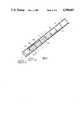
- FIG. 1is a diagrammatic view of a multiple pack of infra-red decoy mortars located within the barrel of launching means;
- FIG. 2is a circuit diagram of the electrical firing arrangement for the mortars of FIG. 1.
- a multiple mortar packcomprising seven mortars 1 to 7 end-to-end relationship is located within the barrel 8 of mortar launching means.
- the mortars 1 to 7are arranged to be fired sequentially by applying firing pulses in turn to pairs of wires P1, P2, P3 to P7 which run along the side of the mortar pack and which are terminated by respective igniters (not shown) located within the mortars 1 to 7.
- a pyrotechnic timing fuse(not shown) is simultaneously ignited and after a predetermined time interval the timing fuse produces ignition of infra-red generating means within the mortar for producing an infra-red aerial display as a decoy for heat-seeking missiles.
- This predetermined time interval between the firing of a mortar and the generation of the infra-red decoy displaywill increase progressively for each mortar fired so that the overall infra-red display will draw the missile away from a missile target (e.g. ship) from which the mortars are fired.
- the firing pulses which are applied sequentially over the pairs of wires P1 to P7are derived from pulse generating means (not shown). These pulses comprise bursts of AC (e.g. 8 to 10 KHz) typically having a duration of about 50 milliseconds.
- ACe.g. 8 to 10 KHz
- the firing pulsesare transmitted through an inductive coupling IC so that they are received between terminals T2 and T3 and applied to a full-wave bridge rectifier RT the dc output of which is applied to the energising coil E of the stepping switch.
- the coil Eis accordingly energised and causes the wipers W1 and W2 to move from their rest position as indicated and away from the rest position contacts of banks BC1 and BC2 towards the first contacts of the banks BC1 and BC2.
- the normally-open contacts C1 and C2 of the stepper switch SWclose so that part of the pulse received over the inductive coupling and developed between terminals T2 and T3 will be applied via the wipers W1 and W2 to the first pair of wires P1 as the wipers make contact with the next arc contacts.
- the wires P1are bridged by the igniter I1 of the top-most mortar of the mortar pack.
- the pulseaccordingly produces fusing of the igniter I1 which causes the mortar to be fired.
- the coil E of the stepper switch SWde-energised and the contacts C1 and C2 will open.
- the contacts TP2 and TP3enable the resistance of the mortar igniters I1 to I7 to be tested when the contacts C1 and C2 are open. Continuity testing of the winding between T2 and T3 can be carried out by holding contacts C1 and C2 closed.
- a short-circuit test for the wiper W1can be carried out between contacts TP1 and TP2.
Landscapes
- Engineering & Computer Science (AREA)
- General Engineering & Computer Science (AREA)
- Toys (AREA)
- Elimination Of Static Electricity (AREA)
- Aiming, Guidance, Guns With A Light Source, Armor, Camouflage, And Targets (AREA)
Abstract
Description
Claims (3)
Applications Claiming Priority (2)
| Application Number | Priority Date | Filing Date | Title |
|---|---|---|---|
| GB08411977AGB2161675B (en) | 1984-05-10 | 1984-05-10 | Improvements relating to electrical firing systems |
| GB8411977 | 1984-05-10 |
Publications (1)
| Publication Number | Publication Date |
|---|---|
| US4709615Atrue US4709615A (en) | 1987-12-01 |
Family
ID=10560747
Family Applications (1)
| Application Number | Title | Priority Date | Filing Date |
|---|---|---|---|
| US06/731,899Expired - LifetimeUS4709615A (en) | 1984-05-10 | 1985-05-08 | Electrical firing systems |
Country Status (3)
| Country | Link |
|---|---|
| US (1) | US4709615A (en) |
| DE (1) | DE3516793C2 (en) |
| GB (1) | GB2161675B (en) |
Cited By (20)
| Publication number | Priority date | Publication date | Assignee | Title |
|---|---|---|---|---|
| US4793258A (en)* | 1986-12-16 | 1988-12-27 | Diehl Gmbh & Co. | Time fuze for unpredictably-detonating scatter ammunition |
| US4960033A (en)* | 1988-12-27 | 1990-10-02 | Electro-Tech, Inc. | Gun firing relay circuit |
| US5062232A (en)* | 1990-02-23 | 1991-11-05 | Eppler Larry D | Safety device for firearms |
| US5883329A (en)* | 1993-03-12 | 1999-03-16 | O'dwyer; James Michael | Barrel assembly |
| US6123007A (en)* | 1993-05-19 | 2000-09-26 | Metal Storm Limited | Barrel assembly |
| US6138395A (en)* | 1995-07-19 | 2000-10-31 | Metal Storm Limited | Barrel assembly with axially stacked projectiles |
| ES2189568A1 (en)* | 1999-12-17 | 2003-07-01 | Nac De La Maranosa Fab | SIMULATOR CARTRIDGE APPLICABLE TO THE TRAINING OF SERVANTS AND VERIFICATION OF NAVAL ANTIMISSILE DEFENSE SYSTEMS. |
| US6782826B1 (en) | 1999-11-18 | 2004-08-31 | Metal Storm Limited | Decoy |
| US20040237762A1 (en)* | 1999-11-03 | 2004-12-02 | Metal Storm Limited | Set defence means |
| US20050188872A1 (en)* | 2004-02-25 | 2005-09-01 | Oertwig Terrance D. | Electronic ignition system for personal black powder firearms |
| RU2274806C1 (en)* | 2004-11-30 | 2006-04-20 | Владимир Васильевич Ящерицын | Device for electric-spark ignition with flame indication |
| US7140301B1 (en) | 1999-11-18 | 2006-11-28 | Metal Storm Limited | Forming temporary airborne images |
| US20070056460A1 (en)* | 2003-05-13 | 2007-03-15 | O'dwyer James M | Modification of a projectile for stacking in a barrel |
| US20070084102A1 (en)* | 2003-05-02 | 2007-04-19 | O'dwyer James M | Combined electrical mechanical firing systems |
| US20070137470A1 (en)* | 2004-02-25 | 2007-06-21 | Oertwig Terrance D | Sequential discharge electronic ignition system for blackpowder firearms |
| US20080121098A1 (en)* | 2006-09-26 | 2008-05-29 | Lockheed Martin Corporation | Electro Magnetic Countermeasure Launcher |
| US20090173328A1 (en)* | 2006-09-26 | 2009-07-09 | Lockheed Martin Corporation | Electromagnetic Initiator Coil |
| US20110073091A1 (en)* | 2001-10-09 | 2011-03-31 | Gowan Carl W | Ball tossing apparatus and method |
| US20140317984A1 (en)* | 2003-02-10 | 2014-10-30 | James Michael O'Dwyer | Selectable kinetic energy of projectiles |
| US10052544B2 (en) | 2014-09-09 | 2018-08-21 | Garza And Gowan Sports Equipment | Ball tossing apparatus and method |
Families Citing this family (3)
| Publication number | Priority date | Publication date | Assignee | Title |
|---|---|---|---|---|
| GB2181523A (en)* | 1985-10-11 | 1987-04-23 | Plessey Co Plc | Missile decoy systems |
| DE3830284C2 (en)* | 1988-09-06 | 1994-01-27 | Deutsch Franz Forsch Inst | Electromagnetic row fire rail cannon |
| DE19910074B4 (en) | 1999-03-08 | 2005-02-10 | Buck Neue Technologien Gmbh | Launcher for shooting a plurality of active bodies as well as litter plant using them |
Citations (5)
| Publication number | Priority date | Publication date | Assignee | Title |
|---|---|---|---|---|
| US1454990A (en)* | 1920-06-28 | 1923-05-15 | Firm Luftschiffbau Zeppelin Gm | Bomb-throwing device for aircraft |
| US3892182A (en)* | 1973-12-10 | 1975-07-01 | Cbf Systems Inc | Squib control circuit |
| US4135455A (en)* | 1977-02-03 | 1979-01-23 | Tracor, Inc. | Multiple payload cartridge employing single pair of electrical connections |
| US4222306A (en)* | 1977-03-07 | 1980-09-16 | Societe E. Lacroix | Decoy-launching packs for foiling guided weapon systems |
| US4586439A (en)* | 1983-05-03 | 1986-05-06 | U.S. Philips Corporation | Cartridge for launching decoys |
Family Cites Families (2)
| Publication number | Priority date | Publication date | Assignee | Title |
|---|---|---|---|---|
| US3712170A (en)* | 1970-06-09 | 1973-01-23 | Us Navy | Aircraft rocket firing system |
| DE2046098C3 (en)* | 1970-09-18 | 1975-11-13 | Licentia Patent-Verwaltungs-Gmbh, 6000 Frankfurt | Circuit arrangement for igniting the detonators of a rocket launcher |
- 1984
- 1984-05-10GBGB08411977Apatent/GB2161675B/ennot_activeExpired
- 1985
- 1985-05-08USUS06/731,899patent/US4709615A/ennot_activeExpired - Lifetime
- 1985-05-09DEDE3516793Apatent/DE3516793C2/ennot_activeExpired - Fee Related
Patent Citations (5)
| Publication number | Priority date | Publication date | Assignee | Title |
|---|---|---|---|---|
| US1454990A (en)* | 1920-06-28 | 1923-05-15 | Firm Luftschiffbau Zeppelin Gm | Bomb-throwing device for aircraft |
| US3892182A (en)* | 1973-12-10 | 1975-07-01 | Cbf Systems Inc | Squib control circuit |
| US4135455A (en)* | 1977-02-03 | 1979-01-23 | Tracor, Inc. | Multiple payload cartridge employing single pair of electrical connections |
| US4222306A (en)* | 1977-03-07 | 1980-09-16 | Societe E. Lacroix | Decoy-launching packs for foiling guided weapon systems |
| US4586439A (en)* | 1983-05-03 | 1986-05-06 | U.S. Philips Corporation | Cartridge for launching decoys |
Cited By (31)
| Publication number | Priority date | Publication date | Assignee | Title |
|---|---|---|---|---|
| US4793258A (en)* | 1986-12-16 | 1988-12-27 | Diehl Gmbh & Co. | Time fuze for unpredictably-detonating scatter ammunition |
| US4960033A (en)* | 1988-12-27 | 1990-10-02 | Electro-Tech, Inc. | Gun firing relay circuit |
| US5062232A (en)* | 1990-02-23 | 1991-11-05 | Eppler Larry D | Safety device for firearms |
| US5883329A (en)* | 1993-03-12 | 1999-03-16 | O'dwyer; James Michael | Barrel assembly |
| US6123007A (en)* | 1993-05-19 | 2000-09-26 | Metal Storm Limited | Barrel assembly |
| US6138395A (en)* | 1995-07-19 | 2000-10-31 | Metal Storm Limited | Barrel assembly with axially stacked projectiles |
| US20040237762A1 (en)* | 1999-11-03 | 2004-12-02 | Metal Storm Limited | Set defence means |
| US7637195B2 (en) | 1999-11-03 | 2009-12-29 | Metal Storm Limited | Set defence means |
| US20080148925A1 (en)* | 1999-11-03 | 2008-06-26 | Metal Storm Limited | Set defence means |
| US6782826B1 (en) | 1999-11-18 | 2004-08-31 | Metal Storm Limited | Decoy |
| US7140301B1 (en) | 1999-11-18 | 2006-11-28 | Metal Storm Limited | Forming temporary airborne images |
| ES2189568A1 (en)* | 1999-12-17 | 2003-07-01 | Nac De La Maranosa Fab | SIMULATOR CARTRIDGE APPLICABLE TO THE TRAINING OF SERVANTS AND VERIFICATION OF NAVAL ANTIMISSILE DEFENSE SYSTEMS. |
| ES2189568B1 (en)* | 1999-12-17 | 2004-10-16 | Fabrica Nacional De La Marañosa | SIMULATOR CARTRIDGE APPLICABLE TO THE TRAINING OF SERVANTS AND VERIFICATION OF NAVAL SYSTEMS OF ANTIMISSILE DEFENSE. |
| US8826895B2 (en)* | 2001-10-09 | 2014-09-09 | Garza And Gowan Sports Equipment | Ball tossing apparatus and method |
| US20110073091A1 (en)* | 2001-10-09 | 2011-03-31 | Gowan Carl W | Ball tossing apparatus and method |
| US9448026B2 (en)* | 2003-02-10 | 2016-09-20 | Defendtex Pty. Ltd. | Selectable kinetic energy of projectiles |
| US20140317984A1 (en)* | 2003-02-10 | 2014-10-30 | James Michael O'Dwyer | Selectable kinetic energy of projectiles |
| US7698849B2 (en) | 2003-05-02 | 2010-04-20 | Metal Storm Limited | Combined electrical mechanical firing systems |
| US20070084102A1 (en)* | 2003-05-02 | 2007-04-19 | O'dwyer James M | Combined electrical mechanical firing systems |
| US8127685B2 (en)* | 2003-05-13 | 2012-03-06 | Metal Storm Limited | Modification of a projectile for stacking in a barrel |
| US20070056460A1 (en)* | 2003-05-13 | 2007-03-15 | O'dwyer James M | Modification of a projectile for stacking in a barrel |
| US20070137470A1 (en)* | 2004-02-25 | 2007-06-21 | Oertwig Terrance D | Sequential discharge electronic ignition system for blackpowder firearms |
| US20070107591A1 (en)* | 2004-02-25 | 2007-05-17 | Oertwig Terrance D | Electronic Ignition system for a Firearm |
| US20050188872A1 (en)* | 2004-02-25 | 2005-09-01 | Oertwig Terrance D. | Electronic ignition system for personal black powder firearms |
| US7197843B2 (en) | 2004-02-25 | 2007-04-03 | Opg Gun Ventures, Llc | Electronic ignition system for a firearm |
| RU2274806C1 (en)* | 2004-11-30 | 2006-04-20 | Владимир Васильевич Ящерицын | Device for electric-spark ignition with flame indication |
| US20090173328A1 (en)* | 2006-09-26 | 2009-07-09 | Lockheed Martin Corporation | Electromagnetic Initiator Coil |
| US8042447B2 (en) | 2006-09-26 | 2011-10-25 | Lockheed Martin Corporation | Electromagnetic initiator coil |
| US7895931B2 (en)* | 2006-09-26 | 2011-03-01 | Lockheed Martin Corporation | Electro magnetic countermeasure launcher |
| US20080121098A1 (en)* | 2006-09-26 | 2008-05-29 | Lockheed Martin Corporation | Electro Magnetic Countermeasure Launcher |
| US10052544B2 (en) | 2014-09-09 | 2018-08-21 | Garza And Gowan Sports Equipment | Ball tossing apparatus and method |
Also Published As
| Publication number | Publication date |
|---|---|
| DE3516793A1 (en) | 1985-11-14 |
| GB2161675B (en) | 1987-07-01 |
| DE3516793C2 (en) | 1994-07-21 |
| GB2161675A (en) | 1986-01-15 |
Similar Documents
| Publication | Publication Date | Title |
|---|---|---|
| US4709615A (en) | Electrical firing systems | |
| US3424924A (en) | Switching system for successive ignition of firing devices at delayed intervals | |
| MX2014007347A (en) | System for triggering a plurality of electronic detonator assemblies. | |
| US2832265A (en) | Squib firing intervalometer | |
| US4708121A (en) | Engine analysers | |
| US4314507A (en) | Sequential initiation of explosives | |
| US3447033A (en) | Laser,weapon simulator | |
| US4489655A (en) | Sequential blasting system | |
| US4162665A (en) | Multi-spark ignition system for internal combustion engines | |
| US3728935A (en) | Coded induction rocket motor ignition system | |
| US3149568A (en) | Remote control system | |
| US2991421A (en) | Fish guidance direct current switching devices | |
| US3722416A (en) | Fuze function selection and firing system | |
| US3153520A (en) | Inertially based sequence programmer | |
| JPH02263098A (en) | Electromagnetic launcher | |
| US4998963A (en) | Explosive logic clock | |
| US3598056A (en) | Fuze | |
| US2988991A (en) | Self destructive torpedo | |
| US4833991A (en) | Submunition incorporating a fuze | |
| US2998773A (en) | Selectively variable timing fuze | |
| US3726494A (en) | Missile power transfer system | |
| US2996991A (en) | One-lead charging system for a timing device | |
| CN113589201A (en) | Intelligent testing device and method for initiating explosive device passage | |
| US4399752A (en) | Solid state switch | |
| US2881702A (en) | Mine firing mechanism |
Legal Events
| Date | Code | Title | Description |
|---|---|---|---|
| AS | Assignment | Owner name:PLESSEY OVERSEAS LIMITED VICARAGE LANE, ILFORD, ES Free format text:ASSIGNMENT OF ASSIGNORS INTEREST.;ASSIGNOR:FIELD, JOHN R.;REEL/FRAME:004403/0995 Effective date:19850419 | |
| STCF | Information on status: patent grant | Free format text:PATENTED CASE | |
| AS | Assignment | Owner name:GEC-MARCONI LIMITED, THE GROVE, WARREN LANE, STANM Free format text:ASSIGNMENT OF ASSIGNORS INTEREST.;ASSIGNOR:PLESSEY OVERSEAS LIMITED;REEL/FRAME:005439/0343 Effective date:19900713 Owner name:GEC-MARCONI LIMITED, ENGLAND Free format text:ASSIGNMENT OF ASSIGNORS INTEREST;ASSIGNOR:PLESSEY OVERSEAS LIMITED;REEL/FRAME:005439/0343 Effective date:19900713 | |
| FEPP | Fee payment procedure | Free format text:PAYOR NUMBER ASSIGNED (ORIGINAL EVENT CODE: ASPN); ENTITY STATUS OF PATENT OWNER: LARGE ENTITY | |
| FPAY | Fee payment | Year of fee payment:4 | |
| FPAY | Fee payment | Year of fee payment:8 | |
| FPAY | Fee payment | Year of fee payment:12 | |
| AS | Assignment | Owner name:MARCONI ELECTRONIC SYSTEMS LIMITED, UNITED KINGDOM Free format text:CHANGE OF NAME;ASSIGNOR:GEC-MARCONI LIMITED;REEL/FRAME:010655/0058 Effective date:19980904 Owner name:ALENIA MARDONI SYSTEMS LIMITED, UNITED KINGDOM Free format text:ASSIGNMENT OF ASSIGNORS INTEREST;ASSIGNOR:MARCONI ELECTRONIC SYSTEMS LIMITED;REEL/FRAME:010655/0074 Effective date:19991201 Owner name:ALENIA MARCONI SYSTEMS LIMITED, UNITED KINGDOM Free format text:ASSIGNMENT OF ASSIGNORS INTEREST;ASSIGNOR:MARCONI ELECTRONIC SYSTEMS LIMITED;REEL/FRAME:010655/0383 Effective date:19991201 Owner name:ALENIA MARDONI SYSTEMS LIMITED,UNITED KINGDOM Free format text:ASSIGNMENT OF ASSIGNORS INTEREST;ASSIGNOR:MARCONI ELECTRONIC SYSTEMS LIMITED;REEL/FRAME:010655/0074 Effective date:19991201 Owner name:ALENIA MARCONI SYSTEMS LIMITED,UNITED KINGDOM Free format text:ASSIGNMENT OF ASSIGNORS INTEREST;ASSIGNOR:MARCONI ELECTRONIC SYSTEMS LIMITED;REEL/FRAME:010655/0383 Effective date:19991201 |