US4709265A - Remote control mobile surveillance system - Google Patents
Remote control mobile surveillance systemDownload PDFInfo
- Publication number
- US4709265A US4709265AUS06/787,338US78733885AUS4709265AUS 4709265 AUS4709265 AUS 4709265AUS 78733885 AUS78733885 AUS 78733885AUS 4709265 AUS4709265 AUS 4709265A
- Authority
- US
- United States
- Prior art keywords
- vehicle
- chassis
- payload
- cover
- remote control
- Prior art date
- Legal status (The legal status is an assumption and is not a legal conclusion. Google has not performed a legal analysis and makes no representation as to the accuracy of the status listed.)
- Expired - Fee Related
Links
- 230000007246mechanismEffects0.000claimsabstractdescription25
- 230000005484gravityEffects0.000claimsabstractdescription18
- 230000033001locomotionEffects0.000claimsdescription15
- 230000009194climbingEffects0.000claimsdescription10
- 230000005540biological transmissionEffects0.000claimsdescription5
- 230000004888barrier functionEffects0.000claimsdescription4
- 238000011109contaminationMethods0.000claimsdescription2
- 230000013011matingEffects0.000claimsdescription2
- 230000003252repetitive effectEffects0.000claimsdescription2
- 238000005096rolling processMethods0.000claims1
- 230000007613environmental effectEffects0.000abstractdescription7
- 231100001261hazardousToxicity0.000abstractdescription5
- 238000012544monitoring processMethods0.000abstractdescription3
- 238000013461designMethods0.000description9
- 238000007689inspectionMethods0.000description7
- 230000035939shockEffects0.000description6
- 239000000853adhesiveSubstances0.000description5
- 230000001070adhesive effectEffects0.000description5
- 239000000463materialSubstances0.000description5
- 230000009471actionEffects0.000description4
- 238000004519manufacturing processMethods0.000description3
- 229920002799BoPETPolymers0.000description2
- 239000005041Mylar™Substances0.000description2
- 238000004458analytical methodMethods0.000description2
- 238000010586diagramMethods0.000description2
- 238000009826distributionMethods0.000description2
- 239000004744fabricSubstances0.000description2
- 239000002184metalSubstances0.000description2
- 229920000728polyesterPolymers0.000description2
- 230000000087stabilizing effectEffects0.000description2
- 238000003860storageMethods0.000description2
- 238000005303weighingMethods0.000description2
- 239000004606Fillers/ExtendersSubstances0.000description1
- 230000002745absorbentEffects0.000description1
- 239000002250absorbentSubstances0.000description1
- 238000010521absorption reactionMethods0.000description1
- 239000002253acidSubstances0.000description1
- 230000004913activationEffects0.000description1
- 230000003321amplificationEffects0.000description1
- 230000002457bidirectional effectEffects0.000description1
- 238000012824chemical productionMethods0.000description1
- 231100000481chemical toxicantToxicity0.000description1
- 238000012864cross contaminationMethods0.000description1
- 238000005520cutting processMethods0.000description1
- 238000005202decontaminationMethods0.000description1
- 230000003588decontaminative effectEffects0.000description1
- 238000006073displacement reactionMethods0.000description1
- 238000005553drillingMethods0.000description1
- 229920002457flexible plasticPolymers0.000description1
- 239000000383hazardous chemicalSubstances0.000description1
- 239000002920hazardous wasteSubstances0.000description1
- 230000004807localizationEffects0.000description1
- 238000012423maintenanceMethods0.000description1
- 238000012986modificationMethods0.000description1
- 230000004048modificationEffects0.000description1
- 238000003199nucleic acid amplification methodMethods0.000description1
- 230000003287optical effectEffects0.000description1
- 238000004091panningMethods0.000description1
- 239000002245particleSubstances0.000description1
- 230000001681protective effectEffects0.000description1
- 230000005855radiationEffects0.000description1
- 230000008439repair processEffects0.000description1
- 230000004044responseEffects0.000description1
- 238000005070samplingMethods0.000description1
- 229910052710siliconInorganic materials0.000description1
- 239000010703siliconSubstances0.000description1
- 239000007787solidSubstances0.000description1
- 230000005236sound signalEffects0.000description1
- 239000000126substanceSubstances0.000description1
- 239000003440toxic substanceSubstances0.000description1
- 230000007704transitionEffects0.000description1
- 230000000007visual effectEffects0.000description1
- 238000003466weldingMethods0.000description1
Images


Classifications
- F—MECHANICAL ENGINEERING; LIGHTING; HEATING; WEAPONS; BLASTING
- F41—WEAPONS
- F41H—ARMOUR; ARMOURED TURRETS; ARMOURED OR ARMED VEHICLES; MEANS OF ATTACK OR DEFENCE, e.g. CAMOUFLAGE, IN GENERAL
- F41H7/00—Armoured or armed vehicles
- F41H7/02—Land vehicles with enclosing armour, e.g. tanks
- B—PERFORMING OPERATIONS; TRANSPORTING
- B62—LAND VEHICLES FOR TRAVELLING OTHERWISE THAN ON RAILS
- B62D—MOTOR VEHICLES; TRAILERS
- B62D1/00—Steering controls, i.e. means for initiating a change of direction of the vehicle
- B62D1/24—Steering controls, i.e. means for initiating a change of direction of the vehicle not vehicle-mounted
- B62D1/28—Steering controls, i.e. means for initiating a change of direction of the vehicle not vehicle-mounted non-mechanical, e.g. following a line or other known markers
- B—PERFORMING OPERATIONS; TRANSPORTING
- B62—LAND VEHICLES FOR TRAVELLING OTHERWISE THAN ON RAILS
- B62D—MOTOR VEHICLES; TRAILERS
- B62D55/00—Endless track vehicles
- B62D55/06—Endless track vehicles with tracks without ground wheels
- B62D55/075—Tracked vehicles for ascending or descending stairs, steep slopes or vertical surfaces
- F—MECHANICAL ENGINEERING; LIGHTING; HEATING; WEAPONS; BLASTING
- F41—WEAPONS
- F41H—ARMOUR; ARMOURED TURRETS; ARMOURED OR ARMED VEHICLES; MEANS OF ATTACK OR DEFENCE, e.g. CAMOUFLAGE, IN GENERAL
- F41H7/00—Armoured or armed vehicles
- F41H7/02—Land vehicles with enclosing armour, e.g. tanks
- F41H7/03—Air-pressurised compartments for crew; Means for preventing admission of noxious substances, e.g. combustion gas from gun barrels, in crew compartments; Sealing arrangements
- G—PHYSICS
- G01—MEASURING; TESTING
- G01N—INVESTIGATING OR ANALYSING MATERIALS BY DETERMINING THEIR CHEMICAL OR PHYSICAL PROPERTIES
- G01N1/00—Sampling; Preparing specimens for investigation
- G01N1/02—Devices for withdrawing samples
- G01N2001/022—Devices for withdrawing samples sampling for security purposes, e.g. contraband, warfare agents
- G—PHYSICS
- G01—MEASURING; TESTING
- G01N—INVESTIGATING OR ANALYSING MATERIALS BY DETERMINING THEIR CHEMICAL OR PHYSICAL PROPERTIES
- G01N1/00—Sampling; Preparing specimens for investigation
- G01N1/02—Devices for withdrawing samples
- G01N2001/028—Sampling from a surface, swabbing, vaporising
Definitions
- the present inventionrelates to a surveillance system having a remotely controlled vehicle for use in hazardous environments, such as nuclear power facilities and toxic chemical manufacturing operations, the vehicle being adapted to monitor a wide variety of environmental conditions and to have optimum mobility throughout a facility.
- the proposed vehiclehas motors, lights, electronic equipment, a communications capability, which also include video transmission capabilities, and batteries for operation remote from a source of high power.
- this and similar prior art systemsteach the use of large, heavy and complex mobile vehicles which normally are tethered to a central control facility by a cable that provides both power and a communications/control capability.
- These vehiclesare very expensive and their broad range of capabilities requires a substantial structure weighing several tons and having significant power requirements.
- such vehiclesoften are limited to predetermined paths and lack the mobility required in multilevel facilities as well as the maneuverability required to move through tight passages, under equipment and around barriers. Notwithstanding their substantial cost, they have significant limitations that prevent them from being cost effective.
- a tethered, remotely-controlled robotis configured to have four independently operating drive track mechanisms each of which supports one corner of a rectangular payload platform.
- Each drive mechanismcomprises a continuous tread belt which is wrapped around a drive sprocket, driving wheels and tensioner wheel.
- the payload platformis equipped with one or two articulated manipulator arms that can be adapted to perform a variety of complex end-effect functions, including holding, lifting, welding and drilling.
- the payload platformalso contains lights and a pair of television cameras which are adapted to provide a stereo-optic view capability to a remote control station.
- a remote control stationAt the control station, an operator may use the stereo-optic viewer and a "joystick" control to operate the device.
- the robotis sized to move through doorways and has a stair-climbing capability which enables it to move about a multilevel facility; however, the vehicle cannot negotiate stairways with small landings. This and similar structures taught in the prior art continue to be complex, weighing a substantial amount and having a weight and length which restricts their maneuverability.
- the prior artteaches mobile vehicles that are tethered by power and telecommunications cables, which provide a further restriction on their maneuverability and the danger of snagging, particularly when moving to another level in a multilevel facility. Additionally, no prior art structure has the capability of obtaining samples from various surfaces within a facility on a repetitive basis, other than through the grabbing capability of an articulated arm with clamping extremities. Finally, all of the prior art devices are complex and, necessarily expensive to manufacture and maintain.
- the present inventionteaches a surveillance system having a unique remotely controlled vehicle.
- the vehicleis designed with a modular structure, is adapted to perform the necessary surveillance functions and is sized to provide optimum manueverability and stability.
- a uniquely shaped chassisis sized to move easily through standard doorways, standard stairways, and narrow passages while having a length sufficient to provide both stability on inclined surfaces and maneuverability in confined spaces, such as landings.
- the vehicleis relatively lightweight and the chassis is designed to accommodate most of the weight at the lowest possible point in the body in order to provide an optimally low center of gravity which is displaced slightly forward of the center of the vehicle.
- the top deck of the vehicleis uniquely shaped and adapted to support any of several payloads mounted at a point forward to center of the vehicle.
- One such payloadis an articulated arm module which comprises a turret containing an articulated arm capable of moving in pan and tilt and having a load affixed to its end which may provide visual, sampling or other sensing capabilities.
- the top coverwhich is adapted to fit over the top of the chassis, slopes down toward the front and sides of the vehicle in order to permit a deployment of the payload in a manner that will augment the vehicle's climbing capabilities by further shifting the center of gravity to an optimum position.
- An independently-operated, motor-driven trackis located on each of the two longitudinal sides of the vehicle; the tracks are adapted to provide motion in a forward, reverse and rotational direction.
- the treadis supported by wheels spaced along the bottom of the chassis and is driven by a motor controlled sprocket.
- a tensioner sprocketis used to provide the proper amount of flexibility to the tread for optimum traction over various types of surfaces.
- the treaditself is adapted to have maximum traction and is shaped to avoid being wedged in standard industrial surfaces such as drain grates and metal stairways.
- the vehicleis adapted to have a plurality of payloads and payload mounts which provide flexibility in a wide variety of industrial applications.
- a standard payloadincludes a rotatable turret mounted on the vehicle deck and having an articulated arm for moving through a horizontal to a vertical direction.
- the armis adapted to contain various loads, including television cameras, smear samplers and the like.
- An object of the present inventionis provision of a lightweight, maneuverable and optimally sized remote control vehicle for sensing the ambient conditions in hazardous environments.
- a further object of the inventionis to provide a remotely controlled vehicle which is free of power, telecommunications, command or control cabling.
- Another object of the inventionis the provision of remote control vehicle having on a top cover, a rotatable turret with an articulated arm and a useful payload at the end thereof and which is also adapted to be moved below the horizontal plane at which the turret joins the top cover, in order to provide a capability of shifting the center of gravity.
- a further object of the inventionis the provision of a remotely controlled vehicle having the capability of taking multiple smear samples from the surfaces of a hazardous environment facility.
- Yet another objectis the provision of a remotely controlled vehicle which is inexpensive to manufacture, easy to control and requires a minimum of maintenance and adjustment.
- Another object of the inventionis to provide a remotely controlled vehicle, having two parallel and independently driven track mechanisms, each disposed along the longitudinal sides and attached to run between the front and back of the vehicle, which is adapted to climb conventional stairways.
- the present inventioncomprises a remotely operated, battery powered, tracked, tetherless vehicle that is adapted to carry multiple payloads, including optics, sensors, smear samplers, articulated or telescoping arms and related control electronics.
- the inventionhas a unique size and shape which permits optimal distribution of the center of gravity for climbing conventional stair cases in industrial facilities.
- the payload packages carrried by the vehiclesare adapted to rotate about a vertical vehicle axis.
- a further embodiment of the inventionincludes a payload incorporating a novel yoke design which is used to provide pan and tilt motion to all payloads (articulated arms, telescoping arms, cameras, sensors, etc.).
- FIGS. 1A, 1B, and 1Cshow a preferred embodiment of the invention having various payloads, including single inspection camera, smear sampler and basic tilted yoke mechanism;
- FIG. 1Dshows the payload in FIG. 1C in a tilt position.
- FIG. 2shows a preferred embodiment of the system for remotely controlling the vehicle.
- FIG. 3shows the silhouette of the vehicle chassis from a top view, with the location of certain components illustrated therein.
- FIG. 4shows the vehicle chassis from a side view.
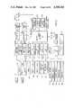
- FIGS. 5A and 5Care block diagrams of the control station electronic subsystem.
- FIG. 5Bis a block diagram of the remote control vehicle electronic subsystem.
- FIGS. 6A and 6Bare illustrated of a preferred tread tensioner design.
- FIG. 7Ais an illustration of a preferred tread design.
- FIG. 7Bis a cross section of the tread design of FIG. 7A.
- FIG. 8Aillustrates one embodiment of an articulated arm payload.
- FIG. 8Billustrates a motor driven load for the arm payload.
- FIG. 8Cillustrates a second embodiment of a rotational payload having a tilt mechanism.
- FIG. 9Ashows the schematic of a smear sampler holder.
- FIG. 9Bshows the schematic of a smear sampler cassette.
- FIG. 10illustrates the tape track system for a smear sampler.
- FIG. 11Aillustrates the base tape design for the smear sampler.
- FIG. 11Billustrates the cover tape design for the smear sampler.
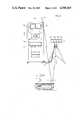
- a remote control vehicle 1having a base chassis 2 and a top cover 3.
- Propulsionis provided by a combination of motors, drive wheels, belt-type tracks and related tensioner mechanisms.
- the chassiscontains six road wheels 10 per side which are mounted to the chassis 2 by stub shafts that are threaded into the chassis.
- a drive wheel 12is located on each side panel of chassis 2 in the upper rear portion of the side panel.
- An idler wheel 11 and tensioner mechanism 14are located at the front portion of each side panel of the chassis 2.
- a continuous belt-like track 8, having a unique tread design,is adapted to wrap around the drive wheel 12, the road wheels 10 and the tensioner wheel 11 on each side of chassis 2.
- the chassisis affixed with a top cover 3 on which are mounted one or more television transmitting antennas 13, a command receive antenna 7 and a payload, which in FIG. 1A is a turret 4, having an articulated arm 5 and camera 6 mounted at the end of the arm.
- the coveris substantially horizontal with a front apron portion, shown as 3a in FIG. 1B, falling from the horizontal plane at an angle a, where a is approximately 25 degrees in a preferred embodiment.
- the angle amay be chosen in a range of 20 to 35 degrees.
- a bumper guard 18is made of rubber or other shock absorbent material and is fixed around the top perimeter of the chassis 2 and provides a shock absorbing capability should the vehicle strike other objects.
- FIG. 1Ba front view of the vehicle 1 is shown.
- the chassis 2has a front side 2a in which a window 9 is located for viewing by a stereo-optic system, as will be described later.
- On each of the longitudinal sides of the chassis 2b and 2cidentical drive tracks 8a and 8b are shown.
- the top cover at each side of the vehiclecan be seen to have two sloping portions 3b and 3c, each of which varies from the vertical by an angle b, where b is approximately 57 degrees in a preferred embodiment.
- the angle bmay be chosen in a range of 40 to 55 degrees.
- FIG. 1Bshows the articulating arm 5 rotated by the turret 4 to one side of the vehicle and illustrates a smear sample mechanism 15 attached to the tip of the arm 5 through a rotatable joint 17 and arm extender 16.
- FIG. 1Cillustrates the basic vehicle 1 with a stereo-optic zoom-lens camera payload 20a mounted on a panable and tiltable platform 20b.
- An illustration of the structure in the forward tilt positionis shown in FIG. 1D. The details of this structure are provided below with respect to the discussion of FIG. 8B.
- a variety of environmental sensing devices (19a and 19b)such as temperature sensor, relative humidity sensors, radiation sensors, chemical sensors, and air quality monitors, may be mounted on the top cover 3 of the vehicle as shown and on the pan and tilt payload 20a.
- Sensor outputis provided to a conventional telemetry communications systems located within the vehicle for transmission by antenna 7.
- Antenna 7is an omnidirectional antenna but may be a rotating directional antenna, as is well known in the art.
- FIG. 2is an illustration of a remote control system for monitoring the environment with the mobile sensing vehicle.
- a supervisory control station 25which is operator controlled through a keyboard 30, joysticks 31a, 31b and 31c as well as switch group 32, permits the operator to drive the vehicle, position it and operate the payload elements.
- the control packagecan contain a four-position joystick that moves the vehicle inspection optics horizontally right and left (pan); moves the articulated arm backward and forward; rotates the inspection optics housing up and down. Vehicle movement is controlled by two-position proportional joysticks that control vehicle motors. Push sticks forward, the vehicle moves forward; pull sticks back, vehicle reverses; one stick forward, one back, the vehicle spins on its axis right or left.
- Vehicle speeddepends on joystick displacement, forward or back, in a conventional manner.
- Two 3-position (normally off) switchesprovide surveillance camera control (inspection optics; zoom-in and zoom-out; focus-in and focus-out).
- the keyboardincludes a two-position switch that provides main power shutoff. Additional miscellaneous functions may be provided by other control switches that may operate ancillary features of the remote vehicle 1 such as drive power on and off switches, smear sampler activation switches, etc. Additional joysticks may be added to perform such functions as: move a telescoping arm in and out; open and close a manipulation on the end of either the telescoping arm or in place of the smear sampler in a manner that is conventional and well known in the prior art.
- the keyboard 30combined with a conventional microprocessor can provide similar or ancillary control functions.
- a 3-D display 29comprises two television monitors and provides the operator with a three-dimensional view of the scene in front of the vehicle.
- Each monitorreceives a TV signal from one of two TV cameras mounted within the body of the vehicle and aligned to view the scene through the transparent port 9, illustrated in FIG. 1B.
- the two scenesare optically merged into a single 3-D view by the 3-D hood 33.
- the operatormay also command the display of television signals from a camera 6 mounted on the articulated arm 5 of the vehicle.
- the inspection camera 6ca be pointed in any direction to inspect equipment, floors, and walls.
- the scene from this camerais displayed on monitor 27a.
- Environmental data, continuously generated by transducers 19A, 19B, etc.,is transmitted by the vehicle communications system to the control station.
- the telemetryWhen received, the telemetry is procesed and displayed to the operator on screen 27b.
- Environmental and vehicle status datais transmitted on the video side bands, formatted by a programmable minicomputer and displayed in a conventional manner as is well known in the prior art.
- Commands from control elements 30-32are transmitted to the vehicle by antenna 26 over an RF link.
- a telecommunications cable 34is connected between the control center 25 and an antenna array 21.
- the arrayincludes two pairs of antennae (22A and 22B), (23A and 23B) which are adapted to receive each of two TV channels redundantly.
- the antenna assemblymay be implemented with a space diversity concept to minimize video signal interference from multipath and other interference with the signal that is broadcast from the vehicle. Two channels of video, with data and audio on the sidebands are each received by a pair of the four antennas seen in the Figure. The strongest signal for each channel may be selected with switching circuitry.
- FIG. 3a top view of chassis 2 is shown to illustrate the placement of certain components.
- Toward the rear of the chassis 2 and on each side thereofis mounted a drive wheel 311a and 311b which are connected by drive shafts 310a and 310b to gear boxes 312a and 312b, respectively.
- Each gear boxis connected to an individually controlled motor 313a and 313b through drive belts 314a and 314b, respectively.
- the drive wheel 311 and gearbox 312are mounted at the top rear of the chassis while the motors 313 are disposed at the lowest rear portion of the chassis.
- the lower rear portion of the chassisis angled upwards in order to provide the necessary clearances during stair climbing and descending operations.
- the optimum angle cas shown in FIG.
- the height h of the chassisis made as small as possible and, given the load requirements for the vehicle, would be in the range of 10 to 12 inches.
- the length of the lower portion of the chassis, identified as 1,is optimally sized to span three conventional stairs and is typically 31 to 33 inches.
- the width of the vehicle, identified as w in FIG. 3is typically 15.5 to 16.5 inches in order to provide maneuverability through doorways and within passageways suitable for travel by personnel.
- Substantially forward of the center of the vehicle and located along the bottom of the chassisare batteries 315.
- These batteriesmay be sealed, lead acid gel batteries which provide the required power for operating the vehicle and its communications system.
- the placement of the batteries at the lowest point in the chassisprovide a low center of gravity which is essential for stair climbing stability.
- the chassisrises at an angle d which is typically in a range of 40 to 60 degrees; in other words the front bow portion is angled upward from the bottom portion at an angle of 120°-140° to provide optimum stair and obstacle climbing capability.
- the stereo-optic viewing port 319permits high resolution, television camera 316a and 316b, having auto zoom capability, to provide a three-dimensional view of the foreground environment for the vehicle.
- the camerasmay have audio pickup microphones either built in or otherwise attached on opposite sides of the vehicle in order to provide a bidirectional sound localization capability.
- a center line, designated in FIGS. 3 and 4 as C--Cmay be used to locate the forward placement of the payload package 317.
- Telecommunications, management and control electronicsare located in removable baskets 318a and 318 b.
- the distribution of weight within and above chassis 2provides a center of gravity which is located in a point C-G, as illustrated in the FIGS. 3 and 4, which is optimally located forward of the center line and low in the chassis 2 in order to provide stability during stair climbing operations.
- the front of the vehicleidentified in FIG. 1B as the side in which the stereo-optic viewing port 9 is located, ordinarily is pointed up the stairs when the vehicle is powered to drive up the incline.
- payload 6which is carried on articulated arm 5 and is connected to turret 4
- the center of gravitywould be approximately 4 inches forward of center and 4 inches above the bottom of the chassis for stair ascent.
- operation of the vehicle in a traverse along an incline slopecan be made more stable by suspending the articulated arm over the up-slope side of the cover 3.
- the sloping face of the cover 3 when combined with the motion of the articulated arm and turret combinationprovides an additional measure of stability that reduces the need for other expensive stabilizing devices such as stabilizing arms or multiple tracks, as shown in the prior art.
- the turret and arm combinationalso provides stability to the vehicle during stair descending operations and, in particular, during the transition of the vehicle from a horizontal disposition to the stair incline such that the vehicle is prevented from tumbling forward over itself. In a maneuver to accomplish this result, the articulated arm is moved dynamically from a forward to a rearward position in order to provide stability as the vehicle transfers from a horizontal to the inclined position.
- FIG. 5Aillustrates the supervisory control station electronic subsystem which operates in a conventional manner but is specifically described with respect to conventional block elements.
- the command panel 501is adapted to provide 15 or more different commands through previously described conventional controls 31 and 32 and to supply them to encoder 502 which provides an information stream in a conventional manner.
- Command control transmitter 503modulates the encoded information onto a carrier which radiates signals through antenna 504 to the receive antenna on the vehicle.
- FIG. 5Billustrates the typical arrangement within the vehicle for controlling its operation.
- the encoded RF signalis picked up by antenna 550c, is forwarded to command/control receiver 553 and is decoded in command control decoder 554 in a conventional manner.
- Appropriate control signalsare transmitted to motor controllers 555a and 555b.
- Control and command servos 557are operated in response to inputs from decoder 554 to provide proper power levels to a variety of related devices such as camera focus motor 560, camera zoom motor 551, articulated arm pan motor 562 and articulated arm tilt motor 563.
- Telemetry antenna 550ais connected to receive the input from microphone 1 and camera 559a, which are connected to subcarrier oscillator 556a, which in turn is connected to transmitter 552A and power amplifier 556a.
- the output from cameras 559b and 559care switchable by servo control switch 558 to provide one or the other of cameras 559b or 559c to subcarrier oscillator 565b.
- the output of that oscillatoris provided to transmitter 552b, whose output is boosted by power amplifier 551b and provided to antenna 550b.
- Telemetryis also provided from transducers 564, 565, 566, 567 and 568 to A/D converter 569. Additional data ports may be provided to the A/D converter as shown.
- the output of the converteris supplied to micro processor 570 whose output is supplied to modem 571 and then to subcarrier oscillator 565B.
- Power supply 572is used to power the transmit and receive subsystem. All of the above functions are conventional in the prior art.
- antennas 507receive the broadcast signals. After amplification by preamp 507, the output is provided to antenna selector 508 which selects the strongest of each pair of redundant signals. The strongest of the first pair is provided to down converter 510, which in turn supplies receiver 511a. The output of receiver 511a is provided to an audio processor 512 and speaker 509. Another output from receiver 511A is sent to a sync stripper 513 and video monitor 514 in a conventional manner. The other selected output channel is provided to down converter 510b operating at a different frequency. The output from the down converter 510B is provided to a second receiver 511b.
- the output from that receiveris supplied to video monitor 515 and sync stripper 516 which in turn supplies the output to video monitor 517 in a conventional manner.
- the output of receiver 511balso is provided to modem 518, which separates out the audio signal (for broadcast through speaker 509) from the data stream and provides the data stream to microprocessor 519 for analysis and display on data monitor 520.
- Video monitors 514 and 517when viewed through the 3-D hood 33 of FIG. 3, provide the operator with a stereo-optic view from the remote control vehicle.
- Video monitor 515provides the input from the inspection optic monitor 6 in FIG. 1A.
- the vehicle propulsion subsystemwhich includes the chassis, batteries, motors, gearboxes, drive wheels, road wheels, tracks, and track tensioners.
- the subsystemis sized for the tracks to span three stair risers on a conventional staircase having a 45° angle. Bow angle, stern angle and height of front top track idler are selected to provide optimum stair and obstacle climbing capability.
- a key to this capabilityis a low center of gravity, as previously discussed.
- the design of the treads and tread tensioneroffers an additional capability for controlling the stability of the device.
- FIGS. 6A and 6Billustrate an embodiment of the tread tensioner which is located external to the chassis and on its side, thereby permitting ready access for adjustment by an operator to adapt to various surfaces, and combines a tensioning mechanism with the front idler wheel 611.
- This unique designadapts to the natural stretch in the tread by incorporating a shock absorbing spring 620.
- Wheel 611comprises two half wheels 611a and 611b, having a common shaft 612 and being supported by extendable arm 614, which is atttached to one end of shaft 615 which slides within bushing 616.
- Shaft 615contains at the other end thereof a hollow portion 623 which contains the shock absorbing spring 620 and is prevented from passing through bushing 616 by met 624.
- Shaft 618is aligned with its longitudinal axis coincident with the longitudinal axis of shaft 615 and is adapted to fit within the hollow portions of shaft 615 and abut the spring within that portion, whereby the spring can be compressed by pressure along the longitudinal axis.
- Shaft 615acts through spring 620 against shaft 618, which is threaded to screw in and out of threaded hole 621 to position idler wheel 611 against the tread, thereby providing proper tread tension.
- the springalso 620 provides shock absorption.
- a lock nut 617is adapted to hold the threaded shaft 611 in place, thereby maintaining a predetermined amount of pressure against the spring. Locknut 617 is loosened to allow tread tensioning by turning shaft 618 at 622.
- a constant pressureis thereby transmitted from the shaft to the wheel 611 and the spring is adapted to absorb any shock which may be developed when the tread impacts against an object.
- the entire mechanismis held by and attached to the vehicle by tensioner body 619.
- the treadcomprises a first belt 702 which is approximately 1/4 inch thick and having raised ridges 703 of approximately 1/4 height and spaced apart approximately 7/8 inches and sized to match with drive wheel 12, as shown in FIG. 1A.
- Another belt 704, which is bonded to belt 702contains tread teeth 705 having a width, approximately 2 9/16 inches, being spaced apart by approximately 13/4 inches and a shape which is adapted to grip stair treads when climbing and to travel over most surfaces without being wedged therein, particularly metal grate surfaces commonly found in industrial facilities.
- the beltsmay be made of a flexible plastic or rubber material which preferably is not porous in order to minimize the effort for decontamination after a mission.
- FIG. 7Bshows a transverse cross-section of the tread.
- a motor 802is attached by bracket 816 to the deck.
- the motorcontains a gear 803 affixed to its drive shaft and is powered from terminals 812.
- a rotatable platform 809 located above the top cover 817,is affixed to rotating mounting post 806 which rides upon center post 818 affixed to deck 800, and has at a lower end a gear 805.
- Belt 804is adapted to convert the rotation of gear 803 into rotation of mounting post 806 and thereby provide a panning capability in a 360° arc about the vertical axis passing through mounting post 806.
- Rotatable platform 809also has mounted to it motor 807 having a worm gear 808.
- a bracket 813is affixed to rotating platform 809 and is adapted to hold in a rotating fashion gear 812, which is attached to arm 811 and has shaft 810 passing centrally therethrough. Operation of motor 807 will turn worm gear 808 and, through its contact with gear 812, causing the arm 811 to rotate through an arc of 180°.
- the above top cover mechanismis encapsulated by a protective cover 815.
- an additional rotational capabilityis provided at the end of arm 811 with a load 820 having a motor 819, attached to arm 810 by bracket 821 and adaptable to be rotated by the motor shaft passing through the arm.
- the inspection optics 820are thus mounted and are rotated in a ⁇ 180 degree arc by motor 819.
- Additional loads which may be carried by the mechanism supported articulated arm 11include a telescoping arm assembly which permits an extension of the arm to a distance of 15 feet.
- the telescoping assemblymay carry a solid particle smear sampler and/or optical equipment or sensing equipment as has been taught by the preferred embodiment of this invention.
- FIG. 8Cillustrates another embodiment of payload 851.
- This embodimentalso provides pan and tilt motion but with a more compact configuration and with motors and mechanisms lower in the vehicle than the embodiment shown in FIG. 8A.
- the majority of mechanism 851is below top cover 817 thus keeping the center of gravity low.
- a pan motor 852drives a gear 861 which interfaces with internal ring gear 862 on turntable 855. Operation of the motor will cause the turntable 855 and all above deck parts of the mechanism to rotate with respect to the top surface 817.
- a tilt motor 853drives a spurgear 854, which drives a drive hub 864, which drives screw drive mechanism 858 vertically up and down.
- the screw drive mechanismis attached to a flat surface 857 by a belt crank 859 that is connected to shaft 858.
- tilt motor 853to move the shaft up or down will result in the mounting surface 857 being tilted about fulcrum 860. Stops are built into the shaft mechanism to limit the direction of travel. A cover 856 seals the drive mechanism and prevents contamination. All below cover parts are connected to mounting structure 863.
- a unique feature of this inventionis its ability to automatically collect samples from the surface of the walls, floor or machinery within a contaminated environment.
- a unique smear sampler apparatuswhich is attached to the payload portion of the articulated arm, either directly by a mating connection 902 or through an extended arm segment 16, as shown in FIG. 1B, is contemplated.
- FIG. 9Aillustrates a smear sampler drive mechanism which contains an adapter 902 for attaching the smear sampler to a payload articulated arm or its extension.
- the sampler holder 915is connected to the arm interface by shaft 905 which is spring loaded against, and rides inside and follows cam slot 904a, thus forcing shaft 905 to rotate when pressure is applied along the longitudinal axis of shaft 905.
- the motoris driven by a battery 911 that is connected in a circuit with the motor by parallel, normally-open switches 912 and 913.
- Switch 912is closed by remote command of the operator through a conventional solenoid or other mechanism.
- switch 913is closed by the movement of the tape across roller switch lever 954, that is mechanically connected to switch 913.
- the base tape 957is loaded into the cassette 951 on roller 953.
- Base tape 957which contains sample patches 958, preferably at four inch intervals, is threaded over idler roller 955b, around sample patch backing pad 956, then back into the cassette over idler roller 955, between rollers 960 and idler 961, and onto sample base tape as it is threaded onto sample takeup roller 952.
- FIGS. 9A and 9Bwhen motor 907 is actuated, the base tape 957 is collected by being rolled onto roller 952 and sample cover tape 954 is automatically applied to cover each sample pad 958 after a sample has been acquired.
- This assembly of base tape, sample patches and cover tape 962is rolled onto sample takeup roller 952 and stored.
- the paper tape 963which protects the adhesive side of cover tape 959 until it is ready for use is also automatically rolled onto sample takeup roller 952.
- FIG. 10is a further illustration of FIG. 9B and shown in three dimensional perspective the action of the various rolls during the smear sampler operation. As can be seen in FIG.
- the sample patch 958is automatically positiond in sample-taking position by a spring loaded indexing roller lever 954 which drops into a slot 966 cut in the base tape.
- the roller level 954is mechanically connected to normally open switch 913 in the holder 915 and the action of the spring loaded roller in dropping into slot 966 will cause switch 913 to open, thereby disconnecting power from motor 907.
- Motor 907can be started again by the operator commanding switch 912 to close, which thereby moves the tape and causes the roller lever to rise out of slot 966 and close switch 913 which continues to operate until the next slot 966 is reached, at the proper position of the next sample pad 958. Again operation is automatically stopped by the indexing roller switch 954 when it drops into the slot in the base tape.
- the smear samplermay be adopted for a hand held operation by substituting a handle at interface 902 and placing in the handle, the battery 911 and switch 912, for manual operation by the operator.
- the sampler systemwill acquire up to 24 samples and protect them from cross contamination.
- FIG. 11Ashows an illustration of a base tape 957 which typically is a mylar, polyester or paper tape, approximately 45 inches long and two and three-quarters inches wide. Affixed to the tape 957 is a number of cloth or paper samplers 958 spaced equally one from the other and centered between the sides of the tape. Each patch 958 is numbered in sequence 967.
- the base tape 957contains an index hole 966 which is located in a position which causes roller switch 954 to drop, thereby cutting power to the drive motor, as explained above.
- the cover tape 959shown in FIG. 11B, is a mylar, polyester or similar material approximately the same length as the base tape 957 and is selectively printed with adhesive that will, when the tape is applied to the base tape 957, bond the two tapes together in areas other than the base tape sampler 958 and thereby isolate the paper or cloth samples from each other.
- the non-adhesive position of cover tape 959is shown as 968 and is sized and oriented to cover and seal patches 958 on the base tape. In the case of each tape, it should be the thinnest, most flexible material possible so that the laminate of base tape and cover tape will roll as tightly as possible.
- the backside of the cover tapemay be treated with silicon or other material so that when the tape is rolled, adhesive side in, the adhesive will not stick to the back of the tape.
- the base tapemay have numbers printed on it for identification of the samples in the laboratory.
Landscapes
- Engineering & Computer Science (AREA)
- General Engineering & Computer Science (AREA)
- Chemical & Material Sciences (AREA)
- Combustion & Propulsion (AREA)
- Transportation (AREA)
- Mechanical Engineering (AREA)
- Closed-Circuit Television Systems (AREA)
- Manipulator (AREA)
Abstract
Description
Claims (14)
Priority Applications (2)
| Application Number | Priority Date | Filing Date | Title |
|---|---|---|---|
| US06/787,338US4709265A (en) | 1985-10-15 | 1985-10-15 | Remote control mobile surveillance system |
| EP86307994AEP0222518A1 (en) | 1985-10-15 | 1986-10-15 | Remote control mobile surveillance system |
Applications Claiming Priority (1)
| Application Number | Priority Date | Filing Date | Title |
|---|---|---|---|
| US06/787,338US4709265A (en) | 1985-10-15 | 1985-10-15 | Remote control mobile surveillance system |
Publications (1)
| Publication Number | Publication Date |
|---|---|
| US4709265Atrue US4709265A (en) | 1987-11-24 |
Family
ID=25141154
Family Applications (1)
| Application Number | Title | Priority Date | Filing Date |
|---|---|---|---|
| US06/787,338Expired - Fee RelatedUS4709265A (en) | 1985-10-15 | 1985-10-15 | Remote control mobile surveillance system |
Country Status (2)
| Country | Link |
|---|---|
| US (1) | US4709265A (en) |
| EP (1) | EP0222518A1 (en) |
Cited By (157)
| Publication number | Priority date | Publication date | Assignee | Title |
|---|---|---|---|---|
| US4905081A (en)* | 1986-11-06 | 1990-02-27 | British Broadcasting Corporation | Method and apparatus for transmitting and receiving 3D video pictures |
| US4993912A (en)* | 1989-12-22 | 1991-02-19 | Chamberlain Mrc, Division Of Duchossois Industries, Inc. | Stair climbing robot |
| US5021878A (en)* | 1989-09-20 | 1991-06-04 | Semborg-Recrob, Corp. | Animated character system with real-time control |
| US5142803A (en)* | 1989-09-20 | 1992-09-01 | Semborg-Recrob, Corp. | Animated character system with real-time contol |
| US5164827A (en)* | 1991-08-22 | 1992-11-17 | Sensormatic Electronics Corporation | Surveillance system with master camera control of slave cameras |
| US5198893A (en)* | 1989-09-20 | 1993-03-30 | Semborg Recrob, Corp. | Interactive animated charater immediately after the title |
| US5216596A (en)* | 1987-04-30 | 1993-06-01 | Corabi International Telemetrics, Inc. | Telepathology diagnostic network |
| US5289090A (en)* | 1991-05-09 | 1994-02-22 | Miller Jeffrey E | Automatic camcorder panning device |
| US5296702A (en)* | 1992-07-28 | 1994-03-22 | Patchen California | Structure and method for differentiating one object from another object |
| US5324948A (en)* | 1992-10-27 | 1994-06-28 | The United States Of America As Represented By The United States Department Of Energy | Autonomous mobile robot for radiologic surveys |
| US5335072A (en)* | 1990-05-30 | 1994-08-02 | Minolta Camera Kabushiki Kaisha | Photographic system capable of storing information on photographed image data |
| US5363935A (en)* | 1993-05-14 | 1994-11-15 | Carnegie Mellon University | Reconfigurable mobile vehicle with magnetic tracks |
| US5408330A (en)* | 1991-03-25 | 1995-04-18 | Crimtec Corporation | Video incident capture system |
| US5416321A (en)* | 1993-04-08 | 1995-05-16 | Coleman Research Corporation | Integrated apparatus for mapping and characterizing the chemical composition of surfaces |
| US5435405A (en)* | 1993-05-14 | 1995-07-25 | Carnegie Mellon University | Reconfigurable mobile vehicle with magnetic tracks |
| US5437203A (en)* | 1992-11-13 | 1995-08-01 | Bruker-Franzen Analytik Gmbh | Sampling device comprising a revolvable sampling wheel with a metal wheel rim |
| US5440916A (en)* | 1993-11-15 | 1995-08-15 | The United States Of America As Represented By The Administrator Of The National Aeronatics And Space Administration | Emergency response mobile robot for operations in combustible atmospheres |
| US5448479A (en)* | 1994-09-01 | 1995-09-05 | Caterpillar Inc. | Remote control system and method for an autonomous vehicle |
| US5448290A (en)* | 1991-08-23 | 1995-09-05 | Go-Video Inc. | Video security system with motion sensor override, wireless interconnection, and mobile cameras |
| US5451135A (en)* | 1993-04-02 | 1995-09-19 | Carnegie Mellon University | Collapsible mobile vehicle |
| US5497188A (en)* | 1993-07-06 | 1996-03-05 | Kaye; Perry | Method for virtualizing an environment |
| US5501112A (en)* | 1993-07-02 | 1996-03-26 | Electric Power Research Institute, Inc. | Retrodictive molecular and particle in-situ snares |
| US5585626A (en)* | 1992-07-28 | 1996-12-17 | Patchen, Inc. | Apparatus and method for determining a distance to an object in a field for the controlled release of chemicals on plants, weeds, trees or soil and/or guidance of farm vehicles |
| US5655945A (en)* | 1992-10-19 | 1997-08-12 | Microsoft Corporation | Video and radio controlled moving and talking device |
| ES2108637A1 (en)* | 1995-07-04 | 1997-12-16 | Nacional De Optica S A Enosa E | Observation and surveillance system |
| US5712782A (en)* | 1995-04-15 | 1998-01-27 | Claas Kgaa | Method of optimizing utilization of a group of agricultural machine |
| US5763873A (en)* | 1996-08-28 | 1998-06-09 | Patchen, Inc. | Photodetector circuit for an electronic sprayer |
| US5781437A (en)* | 1992-04-21 | 1998-07-14 | Ibp Pietzsch Gmbh | Control system for controlling vehicles |
| US5789741A (en)* | 1996-10-31 | 1998-08-04 | Patchen, Inc. | Detecting plants in a field by detecting a change in slope in a reflectance characteristic |
| US5793035A (en)* | 1992-07-28 | 1998-08-11 | Patchen, Inc. | Apparatus and method for spraying herbicide on weeds in a cotton field |
| US5809440A (en)* | 1997-02-27 | 1998-09-15 | Patchen, Inc. | Agricultural implement having multiple agents for mapping fields |
| US6062496A (en)* | 1996-06-17 | 2000-05-16 | Patchen, Inc. | Valve cartridge having pressure sensor for agriculture and weed control |
| GB2344571A (en)* | 1998-12-10 | 2000-06-14 | Bamford Excavators Ltd | A remote controlled vehicle |
| US6079285A (en)* | 1997-10-01 | 2000-06-27 | Baker; Jack T. | Robotic sampler for remote sampling of liquids in a process stream |
| US6113343A (en)* | 1996-12-16 | 2000-09-05 | Goldenberg; Andrew | Explosives disposal robot |
| US6130704A (en)* | 1998-10-22 | 2000-10-10 | Sensormatics Electronics Corporation | Controlling movement of video surveillance cameras |
| US6238265B1 (en)* | 1995-12-29 | 2001-05-29 | Rokenbok Toy Company | Remote control system for operating toys |
| ES2156793A1 (en)* | 1998-02-13 | 2001-07-16 | Ponton Roberto Lopez | Video-advertising remote controlled mobile module |
| US6374155B1 (en) | 1999-11-24 | 2002-04-16 | Personal Robotics, Inc. | Autonomous multi-platform robot system |
| US6375370B1 (en) | 2000-02-10 | 2002-04-23 | Cam Guard Systems, Inc. | Temporary surveillance system |
| USRE37709E1 (en) | 1991-02-11 | 2002-05-21 | Ultrak, Inc. | System for recording and modifying behavior of passenger in passenger vehicles |
| US20030025791A1 (en)* | 2001-06-29 | 2003-02-06 | Kenneth Kaylor | Trailer mounted surveillance system |
| US20030066693A1 (en)* | 2001-10-10 | 2003-04-10 | Louis Marrero | Security vehicle system, vehicle and associated methods |
| US20030066700A1 (en)* | 2001-10-10 | 2003-04-10 | Omnics International Corporation | Security vehicle system, vehicle and associated methods |
| KR20030038960A (en)* | 2001-11-09 | 2003-05-17 | 주식회사 이엠비아이에스 | Monitoring system using mobile robot based on internet |
| US6568983B1 (en)* | 2000-06-20 | 2003-05-27 | Intel Corporation | Video enhanced guided toy vehicles |
| US6701772B2 (en)* | 2000-12-22 | 2004-03-09 | Honeywell International Inc. | Chemical or biological attack detection and mitigation system |
| US6709172B2 (en) | 2000-02-10 | 2004-03-23 | Cam Watch Systems, Inc. | Temporary surveillance system |
| US6741054B2 (en) | 2000-05-02 | 2004-05-25 | Vision Robotics Corporation | Autonomous floor mopping apparatus |
| KR100440771B1 (en)* | 2002-04-08 | 2004-07-21 | 한국수력원자력 주식회사 | Nuclear reactor abnormality diagnosis method and apparatus using CCD camera and thermal infrared camera system |
| US20040162637A1 (en)* | 2002-07-25 | 2004-08-19 | Yulun Wang | Medical tele-robotic system with a master remote station with an arbitrator |
| WO2004111981A1 (en)* | 2003-06-12 | 2004-12-23 | Publirobot, S.L. | Remote-controlled, mobile video advertising unit |
| US20040258404A1 (en)* | 2000-02-10 | 2004-12-23 | Brown Stephen F. | Temporary surveillance system |
| US20050010342A1 (en)* | 2003-07-08 | 2005-01-13 | Shih-Hsiung Li | Driver information feedback and display system |
| US20050012823A1 (en)* | 2003-07-17 | 2005-01-20 | Young Kevin L. | Communication systems, camera devices, and communication methods |
| US20050024213A1 (en)* | 2003-08-01 | 2005-02-03 | David Franzen | Sensor and method of detecting the condition of a turf grass |
| US20050244260A1 (en)* | 2004-04-29 | 2005-11-03 | Comau S.P.A. | Industrial robot |
| USRE38967E1 (en) | 1991-11-12 | 2006-02-07 | K & F Manufacturing, Ltd. | Video monitor and housing assembly |
| US7011171B1 (en) | 2002-10-08 | 2006-03-14 | Poulter Andrew R | Rugged terrain robot |
| WO2006002059A3 (en)* | 2004-06-15 | 2006-05-04 | Rodney Nairne | Turret mount system and method |
| US20060122730A1 (en)* | 2002-10-07 | 2006-06-08 | Esko Niemela | Wireless controller and a method for wireless control of a device mounted on a robot |
| US20060198488A1 (en)* | 2002-03-22 | 2006-09-07 | Framatome Anp | Procedure and means for replacing and procedure for repairing a section of a pipe in the primary circuit of a nuclear reactor |
| US20060259933A1 (en)* | 2005-05-10 | 2006-11-16 | Alan Fishel | Integrated mobile surveillance system |
| US20070112464A1 (en)* | 2002-07-25 | 2007-05-17 | Yulun Wang | Apparatus and method for patient rounding with a remote controlled robot |
| WO2007041038A3 (en)* | 2005-09-30 | 2007-06-28 | Intouch Technologies Inc | A multi-camera mobile teleconferencing platform |
| US7266421B1 (en)* | 1998-11-10 | 2007-09-04 | Commissariat A L'energie Atomique | System for controlling lifting and remote handling units located in a confined enclosure |
| US20070263089A1 (en)* | 2006-05-15 | 2007-11-15 | Mikol Hess | Video recording system-equipped golf cart |
| US20080078599A1 (en)* | 2006-09-29 | 2008-04-03 | Honeywell International Inc. | Vehicle and method for inspecting a space |
| US20080100707A1 (en)* | 2000-02-10 | 2008-05-01 | Cam Guard Systems, Inc. | Temporary surveillance system |
| US20080143063A1 (en)* | 1998-03-27 | 2008-06-19 | Irobot Corporation | Robotic Platform |
| US7464775B2 (en)* | 2003-02-21 | 2008-12-16 | Lockheed Martin Corporation | Payload module for mobility assist |
| US20090040307A1 (en)* | 2005-06-30 | 2009-02-12 | Planum Vision Ltd. | Surveillance System and Method for Detecting Forbidden Movement along a Predetermined Path |
| US20090042607A1 (en)* | 2005-07-01 | 2009-02-12 | Access Co., Ltd. | Broadcast Program Scene Report System and Method, Mobile Terminal Device, and Computer Program |
| WO2009078940A1 (en)* | 2007-12-14 | 2009-06-25 | Foster-Miller, Inc. | Modular mobile robot |
| US7593030B2 (en) | 2002-07-25 | 2009-09-22 | Intouch Technologies, Inc. | Tele-robotic videoconferencing in a corporate environment |
| US20090244279A1 (en)* | 2008-03-26 | 2009-10-01 | Jeffrey Thomas Walsh | Surveillance systems |
| US20090281681A1 (en)* | 2005-09-09 | 2009-11-12 | Ryota Hayashi | Remote-controlled mobile machine using flexible shafts |
| US20090322937A1 (en)* | 2003-07-17 | 2009-12-31 | Battelle Energy Alliance, Llc | Sealed camera assembly and heat removal system therefor |
| US20100030382A1 (en)* | 2008-07-31 | 2010-02-04 | University Of Medicine And Dentistry Of New Jersey | Inhalable particulate environmental robotic sampler |
| US20100095799A1 (en)* | 2008-10-21 | 2010-04-22 | Albin Scott R | End effector for mobile remotely controlled robot |
| US20100101356A1 (en)* | 2008-10-24 | 2010-04-29 | Albin Scott R | Remotely controlled mobile robot in-line robot arm and end effector mechanism |
| US20100115418A1 (en)* | 2004-02-26 | 2010-05-06 | Yulun Wang | Graphical interface for a remote presence system |
| US7726426B2 (en) | 2003-02-21 | 2010-06-01 | Lockheed Martin Corporation | Hub drive and method of using same |
| US20100134604A1 (en)* | 2008-12-02 | 2010-06-03 | Adaptive Methods, Inc. | Deployable sensor device, sensor system, and method of collecting environmental information |
| US7769492B2 (en) | 2006-02-22 | 2010-08-03 | Intouch Technologies, Inc. | Graphical interface for a remote presence system |
| US7813836B2 (en) | 2003-12-09 | 2010-10-12 | Intouch Technologies, Inc. | Protocol for a remotely controlled videoconferencing robot |
| US7896113B1 (en) | 2007-05-12 | 2011-03-01 | Fernando Ramirez | Police robotic system |
| US7916015B1 (en)* | 2004-03-25 | 2011-03-29 | The Johns Hopkins University | System and method for monitoring environmental conditions |
| US20110084162A1 (en)* | 2009-10-09 | 2011-04-14 | Honeywell International Inc. | Autonomous Payload Parsing Management System and Structure for an Unmanned Aerial Vehicle |
| US20110196581A1 (en)* | 2008-10-10 | 2011-08-11 | Thales Suisse Sa | Stabilization of a mast for vehicles and ships |
| US8077963B2 (en) | 2004-07-13 | 2011-12-13 | Yulun Wang | Mobile robot with a head-based movement mapping scheme |
| US8116910B2 (en) | 2007-08-23 | 2012-02-14 | Intouch Technologies, Inc. | Telepresence robot with a printer |
| US8141924B2 (en) | 2008-12-29 | 2012-03-27 | Foster-Miller, Inc. | Gripper system |
| US8170241B2 (en) | 2008-04-17 | 2012-05-01 | Intouch Technologies, Inc. | Mobile tele-presence system with a microphone system |
| GB2485262A (en)* | 2010-10-26 | 2012-05-09 | Anthony John Holker | A motorized camera dolly |
| US8176808B2 (en) | 2007-09-13 | 2012-05-15 | Foster-Miller, Inc. | Robot arm assembly |
| US8179418B2 (en) | 2008-04-14 | 2012-05-15 | Intouch Technologies, Inc. | Robotic based health care system |
| US8322249B2 (en) | 2008-12-18 | 2012-12-04 | Foster-Miller, Inc. | Robot arm assembly |
| US8340819B2 (en) | 2008-09-18 | 2012-12-25 | Intouch Technologies, Inc. | Mobile videoconferencing robot system with network adaptive driving |
| US8384755B2 (en) | 2009-08-26 | 2013-02-26 | Intouch Technologies, Inc. | Portable remote presence robot |
| US8410945B2 (en) | 2002-06-11 | 2013-04-02 | Intelligent Technologies International, Inc | Atmospheric monitoring |
| US20130142297A1 (en)* | 2009-05-27 | 2013-06-06 | R. Brooks Associates, Inc. | Steam generator upper bundle inspection tools |
| US8463435B2 (en) | 2008-11-25 | 2013-06-11 | Intouch Technologies, Inc. | Server connectivity control for tele-presence robot |
| WO2013083924A1 (en)* | 2011-12-08 | 2013-06-13 | Archos | Motorized support for touch-sensitive tablet |
| US20130184917A1 (en)* | 2006-03-06 | 2013-07-18 | Sterraclimb Llc | Stair-climbing wheeled vehicle |
| US20130231814A1 (en)* | 2006-03-06 | 2013-09-05 | Sterraclimb Llc | Stair-climbing surveillance vehicle |
| US20140009561A1 (en)* | 2010-11-12 | 2014-01-09 | Crosswing Inc. | Customizable robotic system |
| US8670017B2 (en) | 2010-03-04 | 2014-03-11 | Intouch Technologies, Inc. | Remote presence system including a cart that supports a robot face and an overhead camera |
| US8672065B2 (en) | 2003-02-21 | 2014-03-18 | Lockheed Martin Corporation | Vehicle having an articulated suspension and method of using same |
| US8718837B2 (en) | 2011-01-28 | 2014-05-06 | Intouch Technologies | Interfacing with a mobile telepresence robot |
| US20140247356A1 (en)* | 2011-09-30 | 2014-09-04 | Siemens S.A.S. | Method and system for determining the availability of a lane for a guided vehicle |
| US8836751B2 (en) | 2011-11-08 | 2014-09-16 | Intouch Technologies, Inc. | Tele-presence system with a user interface that displays different communication links |
| US8839891B2 (en) | 2003-02-21 | 2014-09-23 | Lockheed Martin Corporation | Multi-mode skid steering |
| US8849679B2 (en) | 2006-06-15 | 2014-09-30 | Intouch Technologies, Inc. | Remote controlled robot system that provides medical images |
| US8849680B2 (en) | 2009-01-29 | 2014-09-30 | Intouch Technologies, Inc. | Documentation through a remote presence robot |
| US8892260B2 (en) | 2007-03-20 | 2014-11-18 | Irobot Corporation | Mobile robot for telecommunication |
| US8897920B2 (en) | 2009-04-17 | 2014-11-25 | Intouch Technologies, Inc. | Tele-presence robot system with software modularity, projector and laser pointer |
| US8902278B2 (en) | 2012-04-11 | 2014-12-02 | Intouch Technologies, Inc. | Systems and methods for visualizing and managing telepresence devices in healthcare networks |
| US8930019B2 (en) | 2010-12-30 | 2015-01-06 | Irobot Corporation | Mobile human interface robot |
| US8935005B2 (en) | 2010-05-20 | 2015-01-13 | Irobot Corporation | Operating a mobile robot |
| US8996165B2 (en) | 2008-10-21 | 2015-03-31 | Intouch Technologies, Inc. | Telepresence robot with a camera boom |
| US9014848B2 (en) | 2010-05-20 | 2015-04-21 | Irobot Corporation | Mobile robot system |
| US9075136B1 (en) | 1998-03-04 | 2015-07-07 | Gtj Ventures, Llc | Vehicle operator and/or occupant information apparatus and method |
| US9098611B2 (en) | 2012-11-26 | 2015-08-04 | Intouch Technologies, Inc. | Enhanced video interaction for a user interface of a telepresence network |
| DE19929434B4 (en)* | 1999-06-26 | 2015-09-17 | Karl-Otto Meyer | Mobile dispatch control system for central deployment in hazardous areas |
| US9138891B2 (en) | 2008-11-25 | 2015-09-22 | Intouch Technologies, Inc. | Server connectivity control for tele-presence robot |
| US9160783B2 (en) | 2007-05-09 | 2015-10-13 | Intouch Technologies, Inc. | Robot system that operates through a network firewall |
| US9157569B2 (en) | 2012-10-16 | 2015-10-13 | Polycom Design Inc. | Remote controlled moving platform for a camera |
| US9174342B2 (en) | 2012-05-22 | 2015-11-03 | Intouch Technologies, Inc. | Social behavior rules for a medical telepresence robot |
| US9193065B2 (en) | 2008-07-10 | 2015-11-24 | Intouch Technologies, Inc. | Docking system for a tele-presence robot |
| US9251313B2 (en) | 2012-04-11 | 2016-02-02 | Intouch Technologies, Inc. | Systems and methods for visualizing and managing telepresence devices in healthcare networks |
| US9264664B2 (en) | 2010-12-03 | 2016-02-16 | Intouch Technologies, Inc. | Systems and methods for dynamic bandwidth allocation |
| US9323250B2 (en) | 2011-01-28 | 2016-04-26 | Intouch Technologies, Inc. | Time-dependent navigation of telepresence robots |
| US9361021B2 (en) | 2012-05-22 | 2016-06-07 | Irobot Corporation | Graphical user interfaces including touchpad driving interfaces for telemedicine devices |
| US9498886B2 (en) | 2010-05-20 | 2016-11-22 | Irobot Corporation | Mobile human interface robot |
| US20160341353A1 (en)* | 2015-05-18 | 2016-11-24 | ZipperMast, Inc. | Levelling unit for cameras or sensors |
| US9666071B2 (en) | 2000-09-08 | 2017-05-30 | Intelligent Technologies International, Inc. | Monitoring using vehicles |
| US9670649B2 (en) | 2013-11-25 | 2017-06-06 | Esco Corporation | Wear part monitoring |
| US9842192B2 (en) | 2008-07-11 | 2017-12-12 | Intouch Technologies, Inc. | Tele-presence robot system with multi-cast features |
| US9974612B2 (en) | 2011-05-19 | 2018-05-22 | Intouch Technologies, Inc. | Enhanced diagnostics for a telepresence robot |
| US10011975B2 (en) | 2015-02-13 | 2018-07-03 | Esco Corporation | Monitoring ground-engaging products for earth working equipment |
| US10343283B2 (en) | 2010-05-24 | 2019-07-09 | Intouch Technologies, Inc. | Telepresence robot system that can be accessed by a cellular phone |
| US10546441B2 (en) | 2013-06-04 | 2020-01-28 | Raymond Anthony Joao | Control, monitoring, and/or security, apparatus and method for premises, vehicles, and/or articles |
| US20200231082A1 (en)* | 2019-01-21 | 2020-07-23 | Kevin Arnold Morran | Remote controlled lighting apparatus |
| US10769739B2 (en) | 2011-04-25 | 2020-09-08 | Intouch Technologies, Inc. | Systems and methods for management of information among medical providers and facilities |
| US10808882B2 (en) | 2010-05-26 | 2020-10-20 | Intouch Technologies, Inc. | Tele-robotic system with a robot face placed on a chair |
| US10875182B2 (en) | 2008-03-20 | 2020-12-29 | Teladoc Health, Inc. | Remote presence system mounted to operating room hardware |
| US11034015B2 (en)* | 2016-09-20 | 2021-06-15 | Foster-Miller, Inc. | Remotely controlled packable robot |
| US11154981B2 (en) | 2010-02-04 | 2021-10-26 | Teladoc Health, Inc. | Robot user interface for telepresence robot system |
| US11389064B2 (en) | 2018-04-27 | 2022-07-19 | Teladoc Health, Inc. | Telehealth cart that supports a removable tablet with seamless audio/video switching |
| US11399153B2 (en) | 2009-08-26 | 2022-07-26 | Teladoc Health, Inc. | Portable telepresence apparatus |
| US11636944B2 (en) | 2017-08-25 | 2023-04-25 | Teladoc Health, Inc. | Connectivity infrastructure for a telehealth platform |
| US11742094B2 (en) | 2017-07-25 | 2023-08-29 | Teladoc Health, Inc. | Modular telehealth cart with thermal imaging and touch screen user interface |
| US11862302B2 (en) | 2017-04-24 | 2024-01-02 | Teladoc Health, Inc. | Automated transcription and documentation of tele-health encounters |
| US12093036B2 (en) | 2011-01-21 | 2024-09-17 | Teladoc Health, Inc. | Telerobotic system with a dual application screen presentation |
| US12224059B2 (en) | 2011-02-16 | 2025-02-11 | Teladoc Health, Inc. | Systems and methods for network-based counseling |
| WO2025178874A1 (en)* | 2024-02-19 | 2025-08-28 | Kevin Ross | Use of imaging corresponding with rf beam pattern to facilitate configuring of wireless communication system |
Families Citing this family (7)
| Publication number | Priority date | Publication date | Assignee | Title |
|---|---|---|---|---|
| DE3618885A1 (en)* | 1986-06-05 | 1987-12-10 | Pietzsch Ibp Gmbh | VEHICLE FOR DISASTER PROTECTION, ESPECIALLY IN NUCLEAR SYSTEMS |
| FR2693280B1 (en)* | 1992-07-01 | 1994-09-23 | Alain Milon | Mobile device for moving and positioning one or more optical devices. |
| FR2752982B1 (en)* | 1996-09-03 | 1998-11-27 | Mu 13 Ingenierie Sarl | METHOD AND DEVICE FOR REMOTE CONTROL OF ONE OR MORE CAMERAS |
| DE10258657A1 (en)* | 2002-12-13 | 2004-07-08 | Rheinmetall Landsysteme Gmbh | Device for driving vehicles |
| DE102009010082B4 (en)* | 2009-02-21 | 2016-04-21 | Rheinmetall Landsysteme Gmbh | Probe holder for a vehicle or object |
| CN102381358B (en)* | 2011-09-20 | 2013-07-03 | 北京理工大学 | Ground mobile robot with inflatable car body |
| CN104843100A (en)* | 2015-04-30 | 2015-08-19 | 王英英 | All-terrain movable measurement robot |
Citations (3)
| Publication number | Priority date | Publication date | Assignee | Title |
|---|---|---|---|---|
| US3430496A (en)* | 1967-03-27 | 1969-03-04 | Stacy C Swanberg | Contamination sampler |
| US4483407A (en)* | 1982-03-26 | 1984-11-20 | Hitachi, Ltd. | Variable configuration track laying vehicle |
| US4549208A (en)* | 1982-12-22 | 1985-10-22 | Hitachi, Ltd. | Picture processing apparatus |
Family Cites Families (6)
| Publication number | Priority date | Publication date | Assignee | Title |
|---|---|---|---|---|
| DE1071508B (en)* | 1957-01-03 | |||
| FR1212828A (en)* | 1957-08-27 | 1960-03-25 | Philips Nv | Device for carrying out manipulations using a device controlled, wirelessly, by electrical energy |
| DE2231057C2 (en)* | 1972-06-24 | 1982-11-18 | Kernforschungszentrum Karlsruhe Gmbh, 7500 Karlsruhe | Vehicle with variable chassis geometry |
| US4077483A (en)* | 1975-09-19 | 1978-03-07 | Randolph Arthur J | Invalid vehicle |
| FR2450191A1 (en)* | 1979-03-02 | 1980-09-26 | Maydieu Jacques | Tracked, stair-negotiating Vehicle - is driven by two independent notched tracks and has platform tilting to remain horizontal |
| JPS5812075U (en)* | 1981-07-17 | 1983-01-26 | 三井造船株式会社 | Wall running body of steel structure |
- 1985
- 1985-10-15USUS06/787,338patent/US4709265A/ennot_activeExpired - Fee Related
- 1986
- 1986-10-15EPEP86307994Apatent/EP0222518A1/ennot_activeWithdrawn
Patent Citations (3)
| Publication number | Priority date | Publication date | Assignee | Title |
|---|---|---|---|---|
| US3430496A (en)* | 1967-03-27 | 1969-03-04 | Stacy C Swanberg | Contamination sampler |
| US4483407A (en)* | 1982-03-26 | 1984-11-20 | Hitachi, Ltd. | Variable configuration track laying vehicle |
| US4549208A (en)* | 1982-12-22 | 1985-10-22 | Hitachi, Ltd. | Picture processing apparatus |
Non-Patent Citations (6)
| Title |
|---|
| E. B. Silverman, "Robotic Technology Experiments for Nuclear Power Plant Inspection and Maintenance" (1982), pp. 109-112 ANS Reprint. |
| E. B. Silverman, Robotic Technology Experiments for Nuclear Power Plant Inspection and Maintenance (1982), pp. 109 112 ANS Reprint.* |
| Gupton, "Nuclear Power Plant Emergency Damage Control Robot", Robotic Age, pp. 18-21 (Mar./Apr. 1983). |
| Gupton, Nuclear Power Plant Emergency Damage Control Robot , Robotic Age, pp. 18 21 (Mar./Apr. 1983).* |
| Kohler, "Ferngelenktes Manipulator--Fahrzeug MF3", VDI-Z 120 No. 22 (Nov. 1978). |
| Kohler, Ferngelenktes Manipulator Fahrzeug MF3 , VDI Z 120 No. 22 (Nov. 1978).* |
Cited By (283)
| Publication number | Priority date | Publication date | Assignee | Title |
|---|---|---|---|---|
| US4905081A (en)* | 1986-11-06 | 1990-02-27 | British Broadcasting Corporation | Method and apparatus for transmitting and receiving 3D video pictures |
| US5216596A (en)* | 1987-04-30 | 1993-06-01 | Corabi International Telemetrics, Inc. | Telepathology diagnostic network |
| US5297034A (en)* | 1987-04-30 | 1994-03-22 | Corabi International Telemetrics, Inc. | Telepathology diagnostic network |
| US5142803A (en)* | 1989-09-20 | 1992-09-01 | Semborg-Recrob, Corp. | Animated character system with real-time contol |
| US5198893A (en)* | 1989-09-20 | 1993-03-30 | Semborg Recrob, Corp. | Interactive animated charater immediately after the title |
| US5021878A (en)* | 1989-09-20 | 1991-06-04 | Semborg-Recrob, Corp. | Animated character system with real-time control |
| US4993912A (en)* | 1989-12-22 | 1991-02-19 | Chamberlain Mrc, Division Of Duchossois Industries, Inc. | Stair climbing robot |
| US5335072A (en)* | 1990-05-30 | 1994-08-02 | Minolta Camera Kabushiki Kaisha | Photographic system capable of storing information on photographed image data |
| USRE37709E1 (en) | 1991-02-11 | 2002-05-21 | Ultrak, Inc. | System for recording and modifying behavior of passenger in passenger vehicles |
| US5408330A (en)* | 1991-03-25 | 1995-04-18 | Crimtec Corporation | Video incident capture system |
| US5289090A (en)* | 1991-05-09 | 1994-02-22 | Miller Jeffrey E | Automatic camcorder panning device |
| US5164827A (en)* | 1991-08-22 | 1992-11-17 | Sensormatic Electronics Corporation | Surveillance system with master camera control of slave cameras |
| US5448290A (en)* | 1991-08-23 | 1995-09-05 | Go-Video Inc. | Video security system with motion sensor override, wireless interconnection, and mobile cameras |
| USRE38967E1 (en) | 1991-11-12 | 2006-02-07 | K & F Manufacturing, Ltd. | Video monitor and housing assembly |
| US5781437A (en)* | 1992-04-21 | 1998-07-14 | Ibp Pietzsch Gmbh | Control system for controlling vehicles |
| US5585626A (en)* | 1992-07-28 | 1996-12-17 | Patchen, Inc. | Apparatus and method for determining a distance to an object in a field for the controlled release of chemicals on plants, weeds, trees or soil and/or guidance of farm vehicles |
| US5837997A (en)* | 1992-07-28 | 1998-11-17 | Patchen, Inc. | Structure and method for detecting plants in a field using a light pipe |
| US5296702A (en)* | 1992-07-28 | 1994-03-22 | Patchen California | Structure and method for differentiating one object from another object |
| US5793035A (en)* | 1992-07-28 | 1998-08-11 | Patchen, Inc. | Apparatus and method for spraying herbicide on weeds in a cotton field |
| US5389781A (en)* | 1992-07-28 | 1995-02-14 | Patchen California | Structure and method usable for differentiating a plant from soil in a field |
| US5655945A (en)* | 1992-10-19 | 1997-08-12 | Microsoft Corporation | Video and radio controlled moving and talking device |
| US5324948A (en)* | 1992-10-27 | 1994-06-28 | The United States Of America As Represented By The United States Department Of Energy | Autonomous mobile robot for radiologic surveys |
| US5437203A (en)* | 1992-11-13 | 1995-08-01 | Bruker-Franzen Analytik Gmbh | Sampling device comprising a revolvable sampling wheel with a metal wheel rim |
| US5451135A (en)* | 1993-04-02 | 1995-09-19 | Carnegie Mellon University | Collapsible mobile vehicle |
| US5416321A (en)* | 1993-04-08 | 1995-05-16 | Coleman Research Corporation | Integrated apparatus for mapping and characterizing the chemical composition of surfaces |
| US5363935A (en)* | 1993-05-14 | 1994-11-15 | Carnegie Mellon University | Reconfigurable mobile vehicle with magnetic tracks |
| US5435405A (en)* | 1993-05-14 | 1995-07-25 | Carnegie Mellon University | Reconfigurable mobile vehicle with magnetic tracks |
| US5501112A (en)* | 1993-07-02 | 1996-03-26 | Electric Power Research Institute, Inc. | Retrodictive molecular and particle in-situ snares |
| US5497188A (en)* | 1993-07-06 | 1996-03-05 | Kaye; Perry | Method for virtualizing an environment |
| US5440916A (en)* | 1993-11-15 | 1995-08-15 | The United States Of America As Represented By The Administrator Of The National Aeronatics And Space Administration | Emergency response mobile robot for operations in combustible atmospheres |
| US5448479A (en)* | 1994-09-01 | 1995-09-05 | Caterpillar Inc. | Remote control system and method for an autonomous vehicle |
| US5712782A (en)* | 1995-04-15 | 1998-01-27 | Claas Kgaa | Method of optimizing utilization of a group of agricultural machine |
| ES2108637A1 (en)* | 1995-07-04 | 1997-12-16 | Nacional De Optica S A Enosa E | Observation and surveillance system |
| US6238265B1 (en)* | 1995-12-29 | 2001-05-29 | Rokenbok Toy Company | Remote control system for operating toys |
| US6062496A (en)* | 1996-06-17 | 2000-05-16 | Patchen, Inc. | Valve cartridge having pressure sensor for agriculture and weed control |
| US5763873A (en)* | 1996-08-28 | 1998-06-09 | Patchen, Inc. | Photodetector circuit for an electronic sprayer |
| US5789741A (en)* | 1996-10-31 | 1998-08-04 | Patchen, Inc. | Detecting plants in a field by detecting a change in slope in a reflectance characteristic |
| US6113343A (en)* | 1996-12-16 | 2000-09-05 | Goldenberg; Andrew | Explosives disposal robot |
| US5809440A (en)* | 1997-02-27 | 1998-09-15 | Patchen, Inc. | Agricultural implement having multiple agents for mapping fields |
| US6079285A (en)* | 1997-10-01 | 2000-06-27 | Baker; Jack T. | Robotic sampler for remote sampling of liquids in a process stream |
| ES2156793A1 (en)* | 1998-02-13 | 2001-07-16 | Ponton Roberto Lopez | Video-advertising remote controlled mobile module |
| US9075136B1 (en) | 1998-03-04 | 2015-07-07 | Gtj Ventures, Llc | Vehicle operator and/or occupant information apparatus and method |
| US9573638B2 (en)* | 1998-03-27 | 2017-02-21 | Irobot Defense Holdings, Inc. | Robotic platform |
| US9248874B2 (en) | 1998-03-27 | 2016-02-02 | Irobot Corporation | Robotic platform |
| US8763732B2 (en) | 1998-03-27 | 2014-07-01 | Irobot Corporation | Robotic platform |
| US20080143063A1 (en)* | 1998-03-27 | 2008-06-19 | Irobot Corporation | Robotic Platform |
| US6130704A (en)* | 1998-10-22 | 2000-10-10 | Sensormatics Electronics Corporation | Controlling movement of video surveillance cameras |
| US7266421B1 (en)* | 1998-11-10 | 2007-09-04 | Commissariat A L'energie Atomique | System for controlling lifting and remote handling units located in a confined enclosure |
| US6283220B1 (en) | 1998-12-10 | 2001-09-04 | J.C. Bamford Excavators Limited | Remote control vehicle |
| GB2344571B (en)* | 1998-12-10 | 2002-07-31 | Bamford Excavators Ltd | Remote control vehicle |
| GB2344571A (en)* | 1998-12-10 | 2000-06-14 | Bamford Excavators Ltd | A remote controlled vehicle |
| DE19929434B4 (en)* | 1999-06-26 | 2015-09-17 | Karl-Otto Meyer | Mobile dispatch control system for central deployment in hazardous areas |
| US6496755B2 (en) | 1999-11-24 | 2002-12-17 | Personal Robotics, Inc. | Autonomous multi-platform robot system |
| US6374155B1 (en) | 1999-11-24 | 2002-04-16 | Personal Robotics, Inc. | Autonomous multi-platform robot system |
| US6709171B2 (en) | 2000-02-10 | 2004-03-23 | Cam Watch Systems, Inc. | Temporary surveillance system |
| US20080211905A1 (en)* | 2000-02-10 | 2008-09-04 | Cam Guard Systems, Inc. | Temporary surveillance system |
| US6709172B2 (en) | 2000-02-10 | 2004-03-23 | Cam Watch Systems, Inc. | Temporary surveillance system |
| US20080012941A1 (en)* | 2000-02-10 | 2008-01-17 | Cam Guard Systems, Inc. | Temporary surveillance system |
| US20080100707A1 (en)* | 2000-02-10 | 2008-05-01 | Cam Guard Systems, Inc. | Temporary surveillance system |
| US20040258404A1 (en)* | 2000-02-10 | 2004-12-23 | Brown Stephen F. | Temporary surveillance system |
| US20040264954A1 (en)* | 2000-02-10 | 2004-12-30 | Wesselink Richard H. | Temporary surveillance system |
| US20070248352A1 (en)* | 2000-02-10 | 2007-10-25 | Cam Guard Systems, Inc. | Temporary surveillance system |
| US7267496B2 (en) | 2000-02-10 | 2007-09-11 | Cam Guard Systems, Inc. | Temporary surveillance system |
| US7059783B1 (en) | 2000-02-10 | 2006-06-13 | Cam Guard Systems, Inc. | Temporary surveillance system |
| US7429139B2 (en)* | 2000-02-10 | 2008-09-30 | Cam Guard Systems, Inc. | Temporary surveillance system |
| US20050226610A1 (en)* | 2000-02-10 | 2005-10-13 | Wesselink Richard H | Temporary surveillance system |
| US7465108B2 (en) | 2000-02-10 | 2008-12-16 | Cam Guard Systems, Inc. | Temporary surveillance system |
| US6375370B1 (en) | 2000-02-10 | 2002-04-23 | Cam Guard Systems, Inc. | Temporary surveillance system |
| US7111997B2 (en) | 2000-02-10 | 2006-09-26 | Cam Guard Systems, Inc. | Temporary surveillance system |
| US20060120714A1 (en)* | 2000-02-10 | 2006-06-08 | Wesselink Richard H | Temporary surveillance system |
| US6741054B2 (en) | 2000-05-02 | 2004-05-25 | Vision Robotics Corporation | Autonomous floor mopping apparatus |
| US6568983B1 (en)* | 2000-06-20 | 2003-05-27 | Intel Corporation | Video enhanced guided toy vehicles |
| US9666071B2 (en) | 2000-09-08 | 2017-05-30 | Intelligent Technologies International, Inc. | Monitoring using vehicles |
| US6701772B2 (en)* | 2000-12-22 | 2004-03-09 | Honeywell International Inc. | Chemical or biological attack detection and mitigation system |
| US20030025791A1 (en)* | 2001-06-29 | 2003-02-06 | Kenneth Kaylor | Trailer mounted surveillance system |
| US20030066693A1 (en)* | 2001-10-10 | 2003-04-10 | Louis Marrero | Security vehicle system, vehicle and associated methods |
| US20030066700A1 (en)* | 2001-10-10 | 2003-04-10 | Omnics International Corporation | Security vehicle system, vehicle and associated methods |
| KR20030038960A (en)* | 2001-11-09 | 2003-05-17 | 주식회사 이엠비아이에스 | Monitoring system using mobile robot based on internet |
| US20060198488A1 (en)* | 2002-03-22 | 2006-09-07 | Framatome Anp | Procedure and means for replacing and procedure for repairing a section of a pipe in the primary circuit of a nuclear reactor |
| US7430266B2 (en)* | 2002-03-22 | 2008-09-30 | Framatome Anp | Procedure and means for replacing and procedure for repairing a section of a pipe in the primary circuit of a nuclear reactor |
| KR100440771B1 (en)* | 2002-04-08 | 2004-07-21 | 한국수력원자력 주식회사 | Nuclear reactor abnormality diagnosis method and apparatus using CCD camera and thermal infrared camera system |
| US8410945B2 (en) | 2002-06-11 | 2013-04-02 | Intelligent Technologies International, Inc | Atmospheric monitoring |
| US20040162637A1 (en)* | 2002-07-25 | 2004-08-19 | Yulun Wang | Medical tele-robotic system with a master remote station with an arbitrator |
| US9849593B2 (en) | 2002-07-25 | 2017-12-26 | Intouch Technologies, Inc. | Medical tele-robotic system with a master remote station with an arbitrator |
| US8515577B2 (en) | 2002-07-25 | 2013-08-20 | Yulun Wang | Medical tele-robotic system with a master remote station with an arbitrator |
| US20080029536A1 (en)* | 2002-07-25 | 2008-02-07 | Intouch Technologies, Inc. | Medical tele-robotic system |
| US7593030B2 (en) | 2002-07-25 | 2009-09-22 | Intouch Technologies, Inc. | Tele-robotic videoconferencing in a corporate environment |
| US10315312B2 (en) | 2002-07-25 | 2019-06-11 | Intouch Technologies, Inc. | Medical tele-robotic system with a master remote station with an arbitrator |
| US8209051B2 (en) | 2002-07-25 | 2012-06-26 | Intouch Technologies, Inc. | Medical tele-robotic system |
| US7289883B2 (en) | 2002-07-25 | 2007-10-30 | Intouch Technologies, Inc. | Apparatus and method for patient rounding with a remote controlled robot |
| US20080201017A1 (en)* | 2002-07-25 | 2008-08-21 | Yulun Wang | Medical tele-robotic system |
| US20070112464A1 (en)* | 2002-07-25 | 2007-05-17 | Yulun Wang | Apparatus and method for patient rounding with a remote controlled robot |
| USRE45870E1 (en) | 2002-07-25 | 2016-01-26 | Intouch Technologies, Inc. | Apparatus and method for patient rounding with a remote controlled robot |
| US7979162B2 (en)* | 2002-10-07 | 2011-07-12 | Abb Research Ltd. | Wireless controller and a method for wireless control of a device mounted on a robot |
| US20060122730A1 (en)* | 2002-10-07 | 2006-06-08 | Esko Niemela | Wireless controller and a method for wireless control of a device mounted on a robot |
| US7011171B1 (en) | 2002-10-08 | 2006-03-14 | Poulter Andrew R | Rugged terrain robot |
| US8672065B2 (en) | 2003-02-21 | 2014-03-18 | Lockheed Martin Corporation | Vehicle having an articulated suspension and method of using same |
| US8550192B2 (en) | 2003-02-21 | 2013-10-08 | Lockheed Martin Corporation | Payload module for mobility assist |
| US7464775B2 (en)* | 2003-02-21 | 2008-12-16 | Lockheed Martin Corporation | Payload module for mobility assist |
| US7726426B2 (en) | 2003-02-21 | 2010-06-01 | Lockheed Martin Corporation | Hub drive and method of using same |
| US8839891B2 (en) | 2003-02-21 | 2014-09-23 | Lockheed Martin Corporation | Multi-mode skid steering |
| US9567005B1 (en) | 2003-02-21 | 2017-02-14 | Lockheed Martin Corporation | Multi-mode skid steering |
| WO2004111981A1 (en)* | 2003-06-12 | 2004-12-23 | Publirobot, S.L. | Remote-controlled, mobile video advertising unit |
| US20050010342A1 (en)* | 2003-07-08 | 2005-01-13 | Shih-Hsiung Li | Driver information feedback and display system |
| US6847873B1 (en)* | 2003-07-08 | 2005-01-25 | Shih-Hsiung Li | Driver information feedback and display system |
| US20050012823A1 (en)* | 2003-07-17 | 2005-01-20 | Young Kevin L. | Communication systems, camera devices, and communication methods |
| US20090322937A1 (en)* | 2003-07-17 | 2009-12-31 | Battelle Energy Alliance, Llc | Sealed camera assembly and heat removal system therefor |
| US7362439B2 (en) | 2003-08-01 | 2008-04-22 | Li-Cor, Inc. | Method of detecting the condition of a turf grass |
| US7911616B2 (en) | 2003-08-01 | 2011-03-22 | Li-Cor, Inc. | Sensor and method of detecting the condition of a turf grass |
| US20080316491A1 (en)* | 2003-08-01 | 2008-12-25 | Li-Cor, Inc. | Sensor and method of detecting the condition of a turf grass |
| US7929141B2 (en) | 2003-08-01 | 2011-04-19 | Li-Cor, Inc. | Sensor and method of detecting the condition of a turf grass |
| US8482736B2 (en) | 2003-08-01 | 2013-07-09 | David Franzen | Sensor and method of detecting the condition of a turf grass |
| US20060151680A1 (en)* | 2003-08-01 | 2006-07-13 | David Franzen | Sensor and method of detecting the condition of a turf grass |
| US20050024213A1 (en)* | 2003-08-01 | 2005-02-03 | David Franzen | Sensor and method of detecting the condition of a turf grass |
| US20110235043A1 (en)* | 2003-08-01 | 2011-09-29 | Li-Cor, Inc. | Sensor and method of detecting the condition of a turf grass |
| US9956690B2 (en) | 2003-12-09 | 2018-05-01 | Intouch Technologies, Inc. | Protocol for a remotely controlled videoconferencing robot |
| US7813836B2 (en) | 2003-12-09 | 2010-10-12 | Intouch Technologies, Inc. | Protocol for a remotely controlled videoconferencing robot |
| US10882190B2 (en) | 2003-12-09 | 2021-01-05 | Teladoc Health, Inc. | Protocol for a remotely controlled videoconferencing robot |
| US9375843B2 (en) | 2003-12-09 | 2016-06-28 | Intouch Technologies, Inc. | Protocol for a remotely controlled videoconferencing robot |
| US9610685B2 (en) | 2004-02-26 | 2017-04-04 | Intouch Technologies, Inc. | Graphical interface for a remote presence system |
| US20100115418A1 (en)* | 2004-02-26 | 2010-05-06 | Yulun Wang | Graphical interface for a remote presence system |
| US7916015B1 (en)* | 2004-03-25 | 2011-03-29 | The Johns Hopkins University | System and method for monitoring environmental conditions |
| US20050244260A1 (en)* | 2004-04-29 | 2005-11-03 | Comau S.P.A. | Industrial robot |
| WO2006002059A3 (en)* | 2004-06-15 | 2006-05-04 | Rodney Nairne | Turret mount system and method |
| US20090140117A1 (en)* | 2004-06-15 | 2009-06-04 | Rodney Nairne | Turret mount system and method |
| US8077963B2 (en) | 2004-07-13 | 2011-12-13 | Yulun Wang | Mobile robot with a head-based movement mapping scheme |
| US8983174B2 (en) | 2004-07-13 | 2015-03-17 | Intouch Technologies, Inc. | Mobile robot with a head-based movement mapping scheme |
| US10241507B2 (en) | 2004-07-13 | 2019-03-26 | Intouch Technologies, Inc. | Mobile robot with a head-based movement mapping scheme |
| US9766624B2 (en) | 2004-07-13 | 2017-09-19 | Intouch Technologies, Inc. | Mobile robot with a head-based movement mapping scheme |
| US8401275B2 (en) | 2004-07-13 | 2013-03-19 | Intouch Technologies, Inc. | Mobile robot with a head-based movement mapping scheme |
| US20060259933A1 (en)* | 2005-05-10 | 2006-11-16 | Alan Fishel | Integrated mobile surveillance system |
| US20090040307A1 (en)* | 2005-06-30 | 2009-02-12 | Planum Vision Ltd. | Surveillance System and Method for Detecting Forbidden Movement along a Predetermined Path |
| US20090042607A1 (en)* | 2005-07-01 | 2009-02-12 | Access Co., Ltd. | Broadcast Program Scene Report System and Method, Mobile Terminal Device, and Computer Program |
| US8335597B2 (en)* | 2005-09-09 | 2012-12-18 | Kagoshima University | Remote-controlled mobile machine using flexible shafts |
| US20090281681A1 (en)* | 2005-09-09 | 2009-11-12 | Ryota Hayashi | Remote-controlled mobile machine using flexible shafts |
| WO2007041038A3 (en)* | 2005-09-30 | 2007-06-28 | Intouch Technologies Inc | A multi-camera mobile teleconferencing platform |
| US10259119B2 (en) | 2005-09-30 | 2019-04-16 | Intouch Technologies, Inc. | Multi-camera mobile teleconferencing platform |
| US9198728B2 (en) | 2005-09-30 | 2015-12-01 | Intouch Technologies, Inc. | Multi-camera mobile teleconferencing platform |
| US7769492B2 (en) | 2006-02-22 | 2010-08-03 | Intouch Technologies, Inc. | Graphical interface for a remote presence system |
| US20130231814A1 (en)* | 2006-03-06 | 2013-09-05 | Sterraclimb Llc | Stair-climbing surveillance vehicle |
| US20130184917A1 (en)* | 2006-03-06 | 2013-07-18 | Sterraclimb Llc | Stair-climbing wheeled vehicle |
| US20070263089A1 (en)* | 2006-05-15 | 2007-11-15 | Mikol Hess | Video recording system-equipped golf cart |
| US8849679B2 (en) | 2006-06-15 | 2014-09-30 | Intouch Technologies, Inc. | Remote controlled robot system that provides medical images |
| US20080078599A1 (en)* | 2006-09-29 | 2008-04-03 | Honeywell International Inc. | Vehicle and method for inspecting a space |
| US8892260B2 (en) | 2007-03-20 | 2014-11-18 | Irobot Corporation | Mobile robot for telecommunication |
| US9296109B2 (en) | 2007-03-20 | 2016-03-29 | Irobot Corporation | Mobile robot for telecommunication |
| US10682763B2 (en) | 2007-05-09 | 2020-06-16 | Intouch Technologies, Inc. | Robot system that operates through a network firewall |
| US9160783B2 (en) | 2007-05-09 | 2015-10-13 | Intouch Technologies, Inc. | Robot system that operates through a network firewall |
| US7896113B1 (en) | 2007-05-12 | 2011-03-01 | Fernando Ramirez | Police robotic system |
| US8116910B2 (en) | 2007-08-23 | 2012-02-14 | Intouch Technologies, Inc. | Telepresence robot with a printer |
| US8176808B2 (en) | 2007-09-13 | 2012-05-15 | Foster-Miller, Inc. | Robot arm assembly |
| EP2220542A4 (en)* | 2007-12-14 | 2013-04-03 | Foster Miller Inc | Modular mobile robot |
| AU2008339013B2 (en)* | 2007-12-14 | 2012-08-23 | Foster-Miller, Inc. | Modular mobile robot |
| US8602134B2 (en) | 2007-12-14 | 2013-12-10 | Foster-Miller, Inc. | Modular mobile robot |
| US20110005847A1 (en)* | 2007-12-14 | 2011-01-13 | Andrus Lance L | Modular mobile robot |
| WO2009078940A1 (en)* | 2007-12-14 | 2009-06-25 | Foster-Miller, Inc. | Modular mobile robot |
| US8201649B2 (en)* | 2007-12-14 | 2012-06-19 | Foster-Miller, Inc. | Modular mobile robot |
| US10875182B2 (en) | 2008-03-20 | 2020-12-29 | Teladoc Health, Inc. | Remote presence system mounted to operating room hardware |
| US11787060B2 (en) | 2008-03-20 | 2023-10-17 | Teladoc Health, Inc. | Remote presence system mounted to operating room hardware |
| US20090244279A1 (en)* | 2008-03-26 | 2009-10-01 | Jeffrey Thomas Walsh | Surveillance systems |
| US8179418B2 (en) | 2008-04-14 | 2012-05-15 | Intouch Technologies, Inc. | Robotic based health care system |
| US10471588B2 (en) | 2008-04-14 | 2019-11-12 | Intouch Technologies, Inc. | Robotic based health care system |
| US11472021B2 (en) | 2008-04-14 | 2022-10-18 | Teladoc Health, Inc. | Robotic based health care system |
| US8170241B2 (en) | 2008-04-17 | 2012-05-01 | Intouch Technologies, Inc. | Mobile tele-presence system with a microphone system |
| US9616576B2 (en) | 2008-04-17 | 2017-04-11 | Intouch Technologies, Inc. | Mobile tele-presence system with a microphone system |
| US10493631B2 (en) | 2008-07-10 | 2019-12-03 | Intouch Technologies, Inc. | Docking system for a tele-presence robot |
| US9193065B2 (en) | 2008-07-10 | 2015-11-24 | Intouch Technologies, Inc. | Docking system for a tele-presence robot |
| US9842192B2 (en) | 2008-07-11 | 2017-12-12 | Intouch Technologies, Inc. | Tele-presence robot system with multi-cast features |
| US10878960B2 (en) | 2008-07-11 | 2020-12-29 | Teladoc Health, Inc. | Tele-presence robot system with multi-cast features |
| US20100030382A1 (en)* | 2008-07-31 | 2010-02-04 | University Of Medicine And Dentistry Of New Jersey | Inhalable particulate environmental robotic sampler |
| US9429934B2 (en) | 2008-09-18 | 2016-08-30 | Intouch Technologies, Inc. | Mobile videoconferencing robot system with network adaptive driving |
| US8340819B2 (en) | 2008-09-18 | 2012-12-25 | Intouch Technologies, Inc. | Mobile videoconferencing robot system with network adaptive driving |
| US20110196581A1 (en)* | 2008-10-10 | 2011-08-11 | Thales Suisse Sa | Stabilization of a mast for vehicles and ships |
| US8494725B2 (en)* | 2008-10-10 | 2013-07-23 | Thales Suisse Sa | Stabilization of a mast for vehicles and ships |
| US8414043B2 (en) | 2008-10-21 | 2013-04-09 | Foster-Miller, Inc. | End effector for mobile remotely controlled robot |
| US20100095799A1 (en)* | 2008-10-21 | 2010-04-22 | Albin Scott R | End effector for mobile remotely controlled robot |
| US8996165B2 (en) | 2008-10-21 | 2015-03-31 | Intouch Technologies, Inc. | Telepresence robot with a camera boom |
| US20100101356A1 (en)* | 2008-10-24 | 2010-04-29 | Albin Scott R | Remotely controlled mobile robot in-line robot arm and end effector mechanism |
| US9138891B2 (en) | 2008-11-25 | 2015-09-22 | Intouch Technologies, Inc. | Server connectivity control for tele-presence robot |
| US10059000B2 (en) | 2008-11-25 | 2018-08-28 | Intouch Technologies, Inc. | Server connectivity control for a tele-presence robot |
| US12138808B2 (en) | 2008-11-25 | 2024-11-12 | Teladoc Health, Inc. | Server connectivity control for tele-presence robots |
| US8463435B2 (en) | 2008-11-25 | 2013-06-11 | Intouch Technologies, Inc. | Server connectivity control for tele-presence robot |
| US10875183B2 (en) | 2008-11-25 | 2020-12-29 | Teladoc Health, Inc. | Server connectivity control for tele-presence robot |
| US8174557B2 (en)* | 2008-12-02 | 2012-05-08 | Adaptive Methods, Inc. | Deployable sensor device, sensor system, and method of collecting environmental information |
| US20100134604A1 (en)* | 2008-12-02 | 2010-06-03 | Adaptive Methods, Inc. | Deployable sensor device, sensor system, and method of collecting environmental information |
| US8322249B2 (en) | 2008-12-18 | 2012-12-04 | Foster-Miller, Inc. | Robot arm assembly |
| US8141924B2 (en) | 2008-12-29 | 2012-03-27 | Foster-Miller, Inc. | Gripper system |
| US8849680B2 (en) | 2009-01-29 | 2014-09-30 | Intouch Technologies, Inc. | Documentation through a remote presence robot |
| US10969766B2 (en) | 2009-04-17 | 2021-04-06 | Teladoc Health, Inc. | Tele-presence robot system with software modularity, projector and laser pointer |
| US8897920B2 (en) | 2009-04-17 | 2014-11-25 | Intouch Technologies, Inc. | Tele-presence robot system with software modularity, projector and laser pointer |
| US9251921B2 (en)* | 2009-05-27 | 2016-02-02 | R. Brooks Associates, Inc. | Steam generator upper bundle inspection tools |
| US20130142297A1 (en)* | 2009-05-27 | 2013-06-06 | R. Brooks Associates, Inc. | Steam generator upper bundle inspection tools |
| US10911715B2 (en) | 2009-08-26 | 2021-02-02 | Teladoc Health, Inc. | Portable remote presence robot |
| US11399153B2 (en) | 2009-08-26 | 2022-07-26 | Teladoc Health, Inc. | Portable telepresence apparatus |
| US8384755B2 (en) | 2009-08-26 | 2013-02-26 | Intouch Technologies, Inc. | Portable remote presence robot |
| US10404939B2 (en) | 2009-08-26 | 2019-09-03 | Intouch Technologies, Inc. | Portable remote presence robot |
| US9602765B2 (en) | 2009-08-26 | 2017-03-21 | Intouch Technologies, Inc. | Portable remote presence robot |
| US20110084162A1 (en)* | 2009-10-09 | 2011-04-14 | Honeywell International Inc. | Autonomous Payload Parsing Management System and Structure for an Unmanned Aerial Vehicle |
| US11154981B2 (en) | 2010-02-04 | 2021-10-26 | Teladoc Health, Inc. | Robot user interface for telepresence robot system |
| US10887545B2 (en) | 2010-03-04 | 2021-01-05 | Teladoc Health, Inc. | Remote presence system including a cart that supports a robot face and an overhead camera |
| US9089972B2 (en) | 2010-03-04 | 2015-07-28 | Intouch Technologies, Inc. | Remote presence system including a cart that supports a robot face and an overhead camera |
| US8670017B2 (en) | 2010-03-04 | 2014-03-11 | Intouch Technologies, Inc. | Remote presence system including a cart that supports a robot face and an overhead camera |
| US11798683B2 (en) | 2010-03-04 | 2023-10-24 | Teladoc Health, Inc. | Remote presence system including a cart that supports a robot face and an overhead camera |
| US9902069B2 (en) | 2010-05-20 | 2018-02-27 | Irobot Corporation | Mobile robot system |
| US8935005B2 (en) | 2010-05-20 | 2015-01-13 | Irobot Corporation | Operating a mobile robot |
| US9014848B2 (en) | 2010-05-20 | 2015-04-21 | Irobot Corporation | Mobile robot system |
| US9498886B2 (en) | 2010-05-20 | 2016-11-22 | Irobot Corporation | Mobile human interface robot |
| US10343283B2 (en) | 2010-05-24 | 2019-07-09 | Intouch Technologies, Inc. | Telepresence robot system that can be accessed by a cellular phone |
| US11389962B2 (en) | 2010-05-24 | 2022-07-19 | Teladoc Health, Inc. | Telepresence robot system that can be accessed by a cellular phone |
| US10808882B2 (en) | 2010-05-26 | 2020-10-20 | Intouch Technologies, Inc. | Tele-robotic system with a robot face placed on a chair |
| GB2485262A (en)* | 2010-10-26 | 2012-05-09 | Anthony John Holker | A motorized camera dolly |
| US8994776B2 (en)* | 2010-11-12 | 2015-03-31 | Crosswing Inc. | Customizable robotic system |
| US20140009561A1 (en)* | 2010-11-12 | 2014-01-09 | Crosswing Inc. | Customizable robotic system |
| US10218748B2 (en) | 2010-12-03 | 2019-02-26 | Intouch Technologies, Inc. | Systems and methods for dynamic bandwidth allocation |
| US9264664B2 (en) | 2010-12-03 | 2016-02-16 | Intouch Technologies, Inc. | Systems and methods for dynamic bandwidth allocation |
| US8930019B2 (en) | 2010-12-30 | 2015-01-06 | Irobot Corporation | Mobile human interface robot |
| US12093036B2 (en) | 2011-01-21 | 2024-09-17 | Teladoc Health, Inc. | Telerobotic system with a dual application screen presentation |
| US10591921B2 (en) | 2011-01-28 | 2020-03-17 | Intouch Technologies, Inc. | Time-dependent navigation of telepresence robots |
| US11289192B2 (en) | 2011-01-28 | 2022-03-29 | Intouch Technologies, Inc. | Interfacing with a mobile telepresence robot |
| US8965579B2 (en) | 2011-01-28 | 2015-02-24 | Intouch Technologies | Interfacing with a mobile telepresence robot |
| US9785149B2 (en) | 2011-01-28 | 2017-10-10 | Intouch Technologies, Inc. | Time-dependent navigation of telepresence robots |
| US9323250B2 (en) | 2011-01-28 | 2016-04-26 | Intouch Technologies, Inc. | Time-dependent navigation of telepresence robots |
| US8718837B2 (en) | 2011-01-28 | 2014-05-06 | Intouch Technologies | Interfacing with a mobile telepresence robot |
| US10399223B2 (en) | 2011-01-28 | 2019-09-03 | Intouch Technologies, Inc. | Interfacing with a mobile telepresence robot |
| US11468983B2 (en) | 2011-01-28 | 2022-10-11 | Teladoc Health, Inc. | Time-dependent navigation of telepresence robots |
| US9469030B2 (en) | 2011-01-28 | 2016-10-18 | Intouch Technologies | Interfacing with a mobile telepresence robot |
| US12224059B2 (en) | 2011-02-16 | 2025-02-11 | Teladoc Health, Inc. | Systems and methods for network-based counseling |
| US10769739B2 (en) | 2011-04-25 | 2020-09-08 | Intouch Technologies, Inc. | Systems and methods for management of information among medical providers and facilities |
| US9974612B2 (en) | 2011-05-19 | 2018-05-22 | Intouch Technologies, Inc. | Enhanced diagnostics for a telepresence robot |
| US9533626B2 (en)* | 2011-09-30 | 2017-01-03 | Siemens S.A.S. | Method and system for determining the availability of a lane for a guided vehicle |
| US20140247356A1 (en)* | 2011-09-30 | 2014-09-04 | Siemens S.A.S. | Method and system for determining the availability of a lane for a guided vehicle |
| US8836751B2 (en) | 2011-11-08 | 2014-09-16 | Intouch Technologies, Inc. | Tele-presence system with a user interface that displays different communication links |
| US10331323B2 (en) | 2011-11-08 | 2019-06-25 | Intouch Technologies, Inc. | Tele-presence system with a user interface that displays different communication links |
| US9715337B2 (en) | 2011-11-08 | 2017-07-25 | Intouch Technologies, Inc. | Tele-presence system with a user interface that displays different communication links |
| FR2983939A1 (en)* | 2011-12-08 | 2013-06-14 | Archos | MOTORIZED SUPPORT FOR TOUCH SHELF |
| WO2013083924A1 (en)* | 2011-12-08 | 2013-06-13 | Archos | Motorized support for touch-sensitive tablet |
| US8902278B2 (en) | 2012-04-11 | 2014-12-02 | Intouch Technologies, Inc. | Systems and methods for visualizing and managing telepresence devices in healthcare networks |
| US11205510B2 (en) | 2012-04-11 | 2021-12-21 | Teladoc Health, Inc. | Systems and methods for visualizing and managing telepresence devices in healthcare networks |
| US10762170B2 (en) | 2012-04-11 | 2020-09-01 | Intouch Technologies, Inc. | Systems and methods for visualizing patient and telepresence device statistics in a healthcare network |
| US9251313B2 (en) | 2012-04-11 | 2016-02-02 | Intouch Technologies, Inc. | Systems and methods for visualizing and managing telepresence devices in healthcare networks |
| US9361021B2 (en) | 2012-05-22 | 2016-06-07 | Irobot Corporation | Graphical user interfaces including touchpad driving interfaces for telemedicine devices |
| US10892052B2 (en) | 2012-05-22 | 2021-01-12 | Intouch Technologies, Inc. | Graphical user interfaces including touchpad driving interfaces for telemedicine devices |
| US10061896B2 (en) | 2012-05-22 | 2018-08-28 | Intouch Technologies, Inc. | Graphical user interfaces including touchpad driving interfaces for telemedicine devices |
| US10603792B2 (en) | 2012-05-22 | 2020-03-31 | Intouch Technologies, Inc. | Clinical workflows utilizing autonomous and semiautonomous telemedicine devices |
| US11453126B2 (en) | 2012-05-22 | 2022-09-27 | Teladoc Health, Inc. | Clinical workflows utilizing autonomous and semi-autonomous telemedicine devices |
| US10780582B2 (en) | 2012-05-22 | 2020-09-22 | Intouch Technologies, Inc. | Social behavior rules for a medical telepresence robot |
| US9174342B2 (en) | 2012-05-22 | 2015-11-03 | Intouch Technologies, Inc. | Social behavior rules for a medical telepresence robot |
| US9776327B2 (en) | 2012-05-22 | 2017-10-03 | Intouch Technologies, Inc. | Social behavior rules for a medical telepresence robot |
| US10328576B2 (en) | 2012-05-22 | 2019-06-25 | Intouch Technologies, Inc. | Social behavior rules for a medical telepresence robot |
| US11515049B2 (en) | 2012-05-22 | 2022-11-29 | Teladoc Health, Inc. | Graphical user interfaces including touchpad driving interfaces for telemedicine devices |
| US11628571B2 (en) | 2012-05-22 | 2023-04-18 | Teladoc Health, Inc. | Social behavior rules for a medical telepresence robot |
| US10658083B2 (en) | 2012-05-22 | 2020-05-19 | Intouch Technologies, Inc. | Graphical user interfaces including touchpad driving interfaces for telemedicine devices |
| US9157569B2 (en) | 2012-10-16 | 2015-10-13 | Polycom Design Inc. | Remote controlled moving platform for a camera |
| US10924708B2 (en) | 2012-11-26 | 2021-02-16 | Teladoc Health, Inc. | Enhanced video interaction for a user interface of a telepresence network |
| US11910128B2 (en) | 2012-11-26 | 2024-02-20 | Teladoc Health, Inc. | Enhanced video interaction for a user interface of a telepresence network |
| US10334205B2 (en) | 2012-11-26 | 2019-06-25 | Intouch Technologies, Inc. | Enhanced video interaction for a user interface of a telepresence network |
| US9098611B2 (en) | 2012-11-26 | 2015-08-04 | Intouch Technologies, Inc. | Enhanced video interaction for a user interface of a telepresence network |
| US10546441B2 (en) | 2013-06-04 | 2020-01-28 | Raymond Anthony Joao | Control, monitoring, and/or security, apparatus and method for premises, vehicles, and/or articles |
| US10697154B2 (en) | 2013-11-25 | 2020-06-30 | Esco Group Llc | Wear part monitoring |
| US9670649B2 (en) | 2013-11-25 | 2017-06-06 | Esco Corporation | Wear part monitoring |
| US10683642B2 (en) | 2013-11-25 | 2020-06-16 | Esco Group Llc | Wear part monitoring |
| US10689832B2 (en) | 2013-11-25 | 2020-06-23 | Esco Group Llc | Wear part monitoring |
| US10689833B2 (en) | 2013-11-25 | 2020-06-23 | Esco Group Llc | Wear part monitoring |
| US10024033B2 (en) | 2013-11-25 | 2018-07-17 | Esco Corporation | Wear part monitoring |
| US10669698B2 (en) | 2015-02-13 | 2020-06-02 | Esco Group Llc | Monitoring ground-engaging products for earth working equipment |
| US10633831B2 (en) | 2015-02-13 | 2020-04-28 | Esco Group Llc | Monitoring ground-engaging products for earth working equipment |
| US10612213B2 (en) | 2015-02-13 | 2020-04-07 | Esco Group Llc | Monitoring ground-engaging products for earth working equipment |
| US10760247B2 (en) | 2015-02-13 | 2020-09-01 | Esco Group Llc | Monitoring ground-engaging products for earth working equipment |
| US12104359B2 (en) | 2015-02-13 | 2024-10-01 | Esco Group Llc | Monitoring ground-engaging products for earth working equipment |
| US10787792B2 (en) | 2015-02-13 | 2020-09-29 | Esco Group Llc | Monitoring ground-engaging products for earth working equipment |
| US11851848B2 (en) | 2015-02-13 | 2023-12-26 | Esco Group Llc | Monitoring ground-engaging products for earth working equipment |
| US10011975B2 (en) | 2015-02-13 | 2018-07-03 | Esco Corporation | Monitoring ground-engaging products for earth working equipment |
| US10633832B2 (en) | 2015-02-13 | 2020-04-28 | Esco Group Llc | Monitoring ground-engaging products for earth working equipment |
| US20160341353A1 (en)* | 2015-05-18 | 2016-11-24 | ZipperMast, Inc. | Levelling unit for cameras or sensors |
| US9879816B2 (en)* | 2015-05-18 | 2018-01-30 | ZipperMast, Inc. | Levelling unit for cameras or sensors |
| US11034015B2 (en)* | 2016-09-20 | 2021-06-15 | Foster-Miller, Inc. | Remotely controlled packable robot |
| US11862302B2 (en) | 2017-04-24 | 2024-01-02 | Teladoc Health, Inc. | Automated transcription and documentation of tele-health encounters |
| US11742094B2 (en) | 2017-07-25 | 2023-08-29 | Teladoc Health, Inc. | Modular telehealth cart with thermal imaging and touch screen user interface |
| US11636944B2 (en) | 2017-08-25 | 2023-04-25 | Teladoc Health, Inc. | Connectivity infrastructure for a telehealth platform |
| US11389064B2 (en) | 2018-04-27 | 2022-07-19 | Teladoc Health, Inc. | Telehealth cart that supports a removable tablet with seamless audio/video switching |
| US20210170934A1 (en)* | 2019-01-21 | 2021-06-10 | Kevin Arnold Morran | Mobile Lighting System |
| US20200231082A1 (en)* | 2019-01-21 | 2020-07-23 | Kevin Arnold Morran | Remote controlled lighting apparatus |
| WO2025178874A1 (en)* | 2024-02-19 | 2025-08-28 | Kevin Ross | Use of imaging corresponding with rf beam pattern to facilitate configuring of wireless communication system |
Also Published As
| Publication number | Publication date |
|---|---|
| EP0222518A1 (en) | 1987-05-20 |
Similar Documents
| Publication | Publication Date | Title |
|---|---|---|
| US4709265A (en) | Remote control mobile surveillance system | |
| US4932831A (en) | All terrain mobile robot | |
| US9152148B1 (en) | Spherical integrated remote-control locomotive excursor | |
| US7400348B2 (en) | Remote controlled imaging system | |
| US7011171B1 (en) | Rugged terrain robot | |
| US11040747B2 (en) | Low gravity all-surface vehicle | |
| US6113343A (en) | Explosives disposal robot | |
| US4736826A (en) | Remotely controlled and/or powered mobile robot with cable management arrangement | |
| US5350033A (en) | Robotic inspection vehicle | |
| US4699484A (en) | Rail mounted camera system | |
| JP5247952B2 (en) | Robot system and method of use | |
| US9586636B1 (en) | Multi-segmented magnetic robot | |
| US20080143063A1 (en) | Robotic Platform | |
| US4533998A (en) | Control apparatus for omnidirectional, polar coordinated platform for lawnmower and the like | |
| JPH0392491A (en) | Vehicle having inclination type caterpillar | |
| JP2002307337A (en) | Remote control robot device | |
| US4336858A (en) | Braking system for a medical diagnostic device | |
| CN108313240A (en) | Nuclear power station submerged condition inspection machine people | |
| EP0197020A1 (en) | Remotely-controlled vehicle for inspection and intervention in hostile environments | |
| US5193632A (en) | Vehicle with motorized propulsion units | |
| CN107433621A (en) | A kind of autonomous type lightweight climbing robot detecting system and its application method | |
| JPH0771792B2 (en) | Small all-terrain traveling robot | |
| GB2041879A (en) | Remotely Controllable Mobile Robot and Control Apparatus Therefor | |
| JP2644078B2 (en) | A work vehicle that can handle uneven terrain | |
| JP4504744B2 (en) | Duct cleaning robot camera imaging monitor system and duct cleaning method using the same |
Legal Events
| Date | Code | Title | Description |
|---|---|---|---|
| AS | Assignment | Owner name:ADVANCED RESOURCE DEVELOPMENT CORPORATION,MARYLAND Free format text:ASSIGNMENT OF ASSIGNORS INTEREST;ASSIGNORS:SILVERMAN, EUGENE B.;SIMMONS, RICHARD K.;CROSTON, ROBERT B.;SIGNING DATES FROM 19870507 TO 19870602;REEL/FRAME:004759/0916 Owner name:ADVANCED RESOURCE DEVELOPMENT CORPORATION, 5754 TW Free format text:ASSIGNMENT OF ASSIGNORS INTEREST.;ASSIGNORS:SILVERMAN, EUGENE B.;SIMMONS, RICHARD K.;CROSTON, ROBERT B.;REEL/FRAME:004759/0916;SIGNING DATES FROM 19870507 TO 19870602 | |
| FEPP | Fee payment procedure | Free format text:PAYOR NUMBER ASSIGNED (ORIGINAL EVENT CODE: ASPN); ENTITY STATUS OF PATENT OWNER: SMALL ENTITY | |
| REMI | Maintenance fee reminder mailed | ||
| LAPS | Lapse for failure to pay maintenance fees | ||
| FP | Lapsed due to failure to pay maintenance fee | Effective date:19911124 | |
| AS | Assignment | Owner name:FIRST NATIONAL BANK OF NEW ENGLAND, CONNECTICUT Free format text:SECURITY AGREEMENT;ASSIGNOR:ARD ENVIRONMENTAL, INC.;REEL/FRAME:008989/0001 Effective date:19970530 | |
| AS | Assignment | Owner name:FIRST NATIONAL BANK OF NEW ENGLAND, CONNECTICUT Free format text:SECURITY AGREEMENT;ASSIGNOR:ARD ENVIRONMENTAL, INC.;REEL/FRAME:009097/0537 Effective date:19980326 | |
| AS | Assignment | Owner name:SEQUOIA NATIONAL BANK, MARYLAND Free format text:ASSIGNMENT OF ASSIGNORS INTEREST;ASSIGNOR:ARD ENVIRONMENTAL, INC.;REEL/FRAME:010299/0564 Effective date:19990716 | |
| AS | Assignment | Owner name:SEQUOIA NATIONAL BANK, MARYLAND Free format text:ASSIGNMENT OF ASSIGNORS INTEREST;ASSIGNOR:ARD ENVIRONMENTAL, INC.;REEL/FRAME:010676/0179 Effective date:19990716 | |
| AS | Assignment | Owner name:INTANK TECHNOLOGY INC., MARYLAND Free format text:ASSIGNMENT OF ASSIGNORS INTEREST;ASSIGNOR:ARD ENVIRONMENTAL, INC.;REEL/FRAME:012539/0790 Effective date:20011025 | |
| AS | Assignment | Owner name:CARLYLE/RIVERSTONE GLOBAL ENERGY AND POWER FUND I, Free format text:SECURITY INTEREST;ASSIGNORS:INTANK, INC. (A MARYLAND CORP.);INTANK SERVICES, INC. (A MARYLAND CORP.);INTANK TECHNOLOGY, INC. (A DELAWARE CORP.);REEL/FRAME:014192/0865 Effective date:20031201 | |
| AS | Assignment | Owner name:CARLYLE/RIVERSTONE GLOBAL ENERGY AND POWER FUND I, Free format text:SECURITY AGREEMENT;ASSIGNORS:INTANK, INC. ( A MARYLAND CORP.);INTANK SERVICES, INC. (A MARYLAND CORP.);INTANK TECHNOLOGY, INC. (A DELAWARE CORP.);REEL/FRAME:014242/0923 Effective date:20030912 | |
| AS | Assignment | Owner name:CARLYLE/RIVERSTONE GLOBAL ENERGY AND POWER FUND I, Free format text:SECURITY AGREEMENT;ASSIGNORS:INTANK, INC. (A MARYLAND CORP.);INTANK SERVICES, INC. (A MARYLAND CORP.);INTANK TECHNOLOGY, INC. (A DELAWARE CORP.);REEL/FRAME:014321/0900 Effective date:20040204 | |
| AS | Assignment | Owner name:CARLYLE/RIVERSTONE GLOBAL ENERGY AND POWER FUND I. Free format text:SECURITY INTEREST;ASSIGNORS:INTANK, INC. (A MARYLAND CORP.);INTANK SERVICES, INC. (A MARYLAND CORP.);INTANK TECHNOLOGY, INC. (A DELAWARE CORP.);REEL/FRAME:014468/0220 Effective date:20040302 | |
| AS | Assignment | Owner name:CARLYLE/RIVERSTONE GLOBAL ENERGY AND POWER FUND I. Free format text:SECURITY INTEREST;ASSIGNORS:INTANK, INC. (A MARYLAND CORP.);INTANK SERVICES, INC. (A MARYLAND CORP.);INTANK, TECHNOLOGY, INC. (A DELAWARE CORP.);REEL/FRAME:014523/0807 Effective date:20040414 | |
| AS | Assignment | Owner name:INTANK TECHNOLOGY, INC., MARYLAND Free format text:TERMINATION OF SECURITY INTEREST;ASSIGNORS:FIRST NATIONAL BANK OF NEW ENGLAND;SEQUOIA NATIONAL BANK;REEL/FRAME:014788/0089;SIGNING DATES FROM 19990813 TO 20030912 | |
| AS | Assignment | Owner name:INTANK SERVICES, INC., MARYLAND Free format text:TERMINATION OF RIGHTS AND INTEREST AS TO SECURITY AGREEMENT DATED DECEMBER 1, 2003;ASSIGNOR:CARLYLE/RIVERSTONE GLOBAL ENERGY AND POWER FUND I, L.P.;REEL/FRAME:015386/0713 Effective date:20041015 Owner name:INTANK, INC., MARYLAND Free format text:TERMINATION OF RIGHTS AND INTEREST AS TO SECURITY AGREEMENT DATED DECEMBER 1, 2003;ASSIGNOR:CARLYLE/RIVERSTONE GLOBAL ENERGY AND POWER FUND I, L.P.;REEL/FRAME:015386/0713 Effective date:20041015 Owner name:INTANK TECHNOLOGY, INC., MARYLAND Free format text:TERMINATION OF RIGHTS AND INTEREST AS TO SECURITY AGREEMENT DATED DECEMBER 1, 2003;ASSIGNOR:CARLYLE/RIVERSTONE GLOBAL ENERGY AND POWER FUND I, L.P.;REEL/FRAME:015386/0713 Effective date:20041015 Owner name:INTANK SERVICES, INC., MARYLAND Free format text:TERMINATION OF RIGHTS AND INTEREST AS TO SECURITY AGREEMENT DATED SEPTEMBER 12, 2003;ASSIGNOR:CARLYLE/RIVERSTONE GLOBAL ENERGY AND POWER FUND I, L.P.;REEL/FRAME:015386/0718 Effective date:20041015 Owner name:INTANK, INC., MARYLAND Free format text:TERMINATION OF RIGHTS AND INTEREST AS TO SECURITY AGREEMENT DATED SEPTEMBER 12, 2003;ASSIGNOR:CARLYLE/RIVERSTONE GLOBAL ENERGY AND POWER FUND I, L.P.;REEL/FRAME:015386/0718 Effective date:20041015 Owner name:INTANK TECHNOLOGY, INC., MARYLAND Free format text:TERMINATION OF RIGHTS AND INTEREST AS TO SECURITY AGREEMENT DATED SEPTEMBER 12, 2003;ASSIGNOR:CARLYLE/RIVERSTONE GLOBAL ENERGY AND POWER FUND I, L.P.;REEL/FRAME:015386/0718 Effective date:20041015 Owner name:INTANK SERVICES, INC., MARYLAND Free format text:TERMINATION OF RIGHTS AND INTEREST AS TO SECURITY AGREEMENT DATED MARCH 2, 2004;ASSIGNOR:CARLYLE/RIVERSTONE GLOBAL ENERGY AND POWER FUND I, L.P.;REEL/FRAME:015386/0723 Effective date:20041015 Owner name:INTANK, INC., MARYLAND Free format text:TERMINATION OF RIGHTS AND INTEREST AS TO SECURITY AGREEMENT DATED MARCH 2, 2004;ASSIGNOR:CARLYLE/RIVERSTONE GLOBAL ENERGY AND POWER FUND I, L.P.;REEL/FRAME:015386/0723 Effective date:20041015 Owner name:INTANK TECHNOLOGY, INC., MARYLAND Free format text:TERMINATION OF RIGHTS AND INTEREST AS TO SECURITY AGREEMENT DATED MARCH 2, 2004;ASSIGNOR:CARLYLE/RIVERSTONE GLOBAL ENERGY AND POWER FUND I, L.P.;REEL/FRAME:015386/0723 Effective date:20041015 Owner name:INTANK SERVICES, INC., MARYLAND Free format text:TERMINATION OF RIGHTS AND INTEREST AS TO SECURITY AGREEMENT DATED APRIL 14, 2004;ASSIGNOR:CARLYLE/RIVERSTONE GLOBAL ENERGY AND POWER FUND I, L.P.;REEL/FRAME:015386/0728 Effective date:20041015 Owner name:INTANK, INC., MARYLAND Free format text:TERMINATION OF RIGHTS AND INTEREST AS TO SECURITY AGREEMENT DATED APRIL 14, 2004;ASSIGNOR:CARLYLE/RIVERSTONE GLOBAL ENERGY AND POWER FUND I, L.P.;REEL/FRAME:015386/0728 Effective date:20041015 Owner name:INTANK TECHNOLOGY, INC., MARYLAND Free format text:TERMINATION OF RIGHTS AND INTEREST AS TO SECURITY AGREEMENT DATED APRIL 14, 2004;ASSIGNOR:CARLYLE/RIVERSTONE GLOBAL ENERGY AND POWER FUND I, L.P.;REEL/FRAME:015386/0728 Effective date:20041015 Owner name:INTANK SERVICES, INC., MARYLAND Free format text:TERMINATION OF RIGHTS AND INTEREST AS TO SECURITY AGREEMENT DATED FEBRUARY 4, 2004;ASSIGNOR:CARLYLE/RIVERSTONE GLOBAL ENERGY AND POWER FUND I, L.P.;REEL/FRAME:015386/0733 Effective date:20041015 Owner name:INTANK, INC., MARYLAND Free format text:TERMINATION OF RIGHTS AND INTEREST AS TO SECURITY AGREEMENT DATED FEBRUARY 4, 2004;ASSIGNOR:CARLYLE/RIVERSTONE GLOBAL ENERGY AND POWER FUND I, L.P.;REEL/FRAME:015386/0733 Effective date:20041015 Owner name:INTANK TECHNOLOGY, INC., MARYLAND Free format text:TERMINATION OF RIGHTS AND INTEREST AS TO SECURITY AGREEMENT DATED FEBRUARY 4, 2004;ASSIGNOR:CARLYLE/RIVERSTONE GLOBAL ENERGY AND POWER FUND I, L.P.;REEL/FRAME:015386/0733 Effective date:20041015 | |
| STCH | Information on status: patent discontinuation | Free format text:PATENT EXPIRED DUE TO NONPAYMENT OF MAINTENANCE FEES UNDER 37 CFR 1.362 |