US4709239A - Dipatch antenna - Google Patents
Dipatch antennaDownload PDFInfo
- Publication number
- US4709239A US4709239AUS06/773,699US77369985AUS4709239AUS 4709239 AUS4709239 AUS 4709239AUS 77369985 AUS77369985 AUS 77369985AUS 4709239 AUS4709239 AUS 4709239A
- Authority
- US
- United States
- Prior art keywords
- radiating element
- antenna
- recited
- radiating
- patch
- Prior art date
- Legal status (The legal status is an assumption and is not a legal conclusion. Google has not performed a legal analysis and makes no representation as to the accuracy of the status listed.)
- Expired - Lifetime
Links
- 230000010287polarizationEffects0.000claimsdescription10
- 229910052751metalInorganic materials0.000claimsdescription3
- 239000002184metalSubstances0.000claimsdescription3
- 239000007787solidSubstances0.000claimsdescription2
- 230000008878couplingEffects0.000claims1
- 238000010168coupling processMethods0.000claims1
- 238000005859coupling reactionMethods0.000claims1
- 238000003491arrayMethods0.000description2
- 230000005540biological transmissionEffects0.000description2
- 238000013461designMethods0.000description2
- 238000005259measurementMethods0.000description2
- 238000000034methodMethods0.000description2
- 238000004806packaging method and processMethods0.000description2
- 230000005855radiationEffects0.000description2
- 230000006978adaptationEffects0.000description1
- 229910052782aluminiumInorganic materials0.000description1
- XAGFODPZIPBFFR-UHFFFAOYSA-NaluminiumChemical compound[Al]XAGFODPZIPBFFR-UHFFFAOYSA-N0.000description1
- 238000013459approachMethods0.000description1
- 239000003989dielectric materialSubstances0.000description1
- 238000001914filtrationMethods0.000description1
- 238000012986modificationMethods0.000description1
- 230000004048modificationEffects0.000description1
- 230000035939shockEffects0.000description1
- 239000012780transparent materialSubstances0.000description1
Images


Classifications
- H—ELECTRICITY
- H01—ELECTRIC ELEMENTS
- H01Q—ANTENNAS, i.e. RADIO AERIALS
- H01Q1/00—Details of, or arrangements associated with, antennas
- H01Q1/27—Adaptation for use in or on movable bodies
- H01Q1/28—Adaptation for use in or on aircraft, missiles, satellites, or balloons
- H01Q1/282—Modifying the aerodynamic properties of the vehicle, e.g. projecting type aerials
- H—ELECTRICITY
- H01—ELECTRIC ELEMENTS
- H01Q—ANTENNAS, i.e. RADIO AERIALS
- H01Q9/00—Electrically-short antennas having dimensions not more than twice the operating wavelength and consisting of conductive active radiating elements
- H01Q9/04—Resonant antennas
- H01Q9/0407—Substantially flat resonant element parallel to ground plane, e.g. patch antenna
- H01Q9/0442—Substantially flat resonant element parallel to ground plane, e.g. patch antenna with particular tuning means
Definitions
- the present inventionrelates to antennas and more particularly to a dispatch antenna providing vertical polarization and wideband, rapid tuning in an aerodynamically efficient package.
- VHFVery High Frequency
- UHFUltra High Frequency
- An ideal antennawould have an aerodynamically efficient shape, less than one square foot forward cross-sectional area, and be adapted for existing aircraft antenna pods.
- Such an antennashould have a substantially omnidirectional radiation pattern while maintaining a Voltage Standing Wave Ratio (VSWR) of less than to one (2:1) over a five to one (5:1) tuning range.
- VSWRVoltage Standing Wave Ratio
- a parallel plate antennaconfigured as a thin disk of dielectric material plated on both sides can be used as an edge slot radiator to achieve the required vertical polarization. Rows of diametrically opposed tuning posts can be used to set the operating frequency. See, for example, D. H. Schaubert, H. S. Jones, Jr. and F. Reggia, "Conformal Dielectric-Filled Edge-Slot Antennas with Inductive-Post Tuning," IEEE Transactions on Antennas and Propagation, vol. AP-27, No. 5, pp. 713-716 September 1979.
- the edge slothas the desired vertical polarization.
- the basic parallel plate structureexhibits a typical 2:1 VSWR bandwidth of only approximately three to five percent. Additionally, the disk shape is not particularly adaptable to existing aerodynamic pods.
- Another object of the present inventionis to provide an antenna easily adaptable to existing aerodynamic packaging techniques.
- a further object of the present inventionis to provide an antenna which is rapidly tunable.
- Yet another object of the present inventionis to provide an antenna capable of maintaining a VSWR of less than two to one over at least a five to one bandwidth.
- a still further object of the present inventionis to provide an antenna suitable for efficient, high power transmission in excess of one kilowatt.
- an antennaconfigured as a conductive patch spaced over its image.
- the patchesare shaped to conform to the various existing aircraft antenna packages, such as pods.
- the use of air as a dielectricsubstantially increases the instantaneous bandwidth available at the frequencies of interest.
- the addition of approximately ten shorting devices, disposed along and connected between the patches to provide electrical shorts at selectable positions,allows rapid tuning over a 5:1 bandwidth while maintaining the desired 2:1 VSWR.
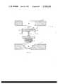
- FIG. 1is an isometric view of a preferred embodiment of the dipatch antenna in accordance with the present invention
- FIG. 2is a partial cross sectional view of the embodiment of FIG. 1 showing a preferred diode mounting technique
- FIG. 3is a cross sectional view of a preferred embodiment of a conformal aircraft pod mounting arrangement for the present invention.
- FIGS. 4-9show various radiation patterns obtained using the embodiment of FIG. 1.
- FIG. 1an isometric view of the preferred embodiment.
- An upper conductive metallic plate 10is used as a patch type antenna element.
- This upper patch 10is configured to conform to the geometry of existing aerodynamic pods. Its length should be approximately equal to one-half the wavelength of the lowest frequency of interest.
- a lower patch 12is positioned beneath the top patch 10. This lower patch 12 is physically identical to the upper patch 10 and positioned and electrically operated to form the image of upper patch 10. Radio frequency energy is coupled to upper patch 10 and lower patch 12.
- Input coaxial connector 16provides an input from the radio frequency source (not shown). Connection of such a coaxial connector is further described in U.S. Pat. No.
- a plurality of shorting modules 14,are linearly disposed along the major axis of and between conductive patches 10 and 12. Shorting modules 14 need not be positioned exactly on the major axis, but merely parallel to it, as shifting a bit off-center only adjusts the driving point impedance.
- Each shorting module 14has a bias control lead 18 used to switch each shorting module 14 between a full-on and full-off state.
- the bias control leads 18are connected through cabling to a bias control circuit (not shown) which controls the state of each shorting module 14.
- PINPositive-Intrinsic Negative
- the upper and lower patches, 10 and 12are approximately 9 inches in length and 21/2 inches in width, with the air space between patches 10 and 12 being approximately 3/8 of an inch. Approximately ten shorting modules 14 are sufficient to cover this frequency range.
- FIG. 2is a more detailed view of a shorting module 14 and its interface with upper patch 10 and lower patch 12.
- shorting module 14comprises a PIN diode 20 in a stud mount configuration, so that the screw threads 22 at the bottom of the stud mount engage the lower patch 12 via the tapped threaded hole 32 formed as a part of lower patch 12.
- the bias control lead 18 associated with each shorting module 14is preferably connected to the PIN diode 20's bias control input with a push on lug 24 or similar input terminal.
- a capacitive bypass network 26is preferably disposed between push-on lug 24 and the PIN diode 20 to shunt RF currents to the upper patch 10, thereby effectively filtering any switching transients out of bias control line 18.
- a cylindrical sleeve 28is preferably fitted around the lug 24, bypass network 26, PIN diode 20 and stud mount 22 assembly.
- the sleeve 28has a compresssive portion 30, which allows the PIN diode 20 to both electrically and mechanically engage the upper patch 10 when the shorting module 14 is properly positioned underneath the holes 34 formed as a part of upper patch 10.
- FIG. 3is a cross-sectional view of the pod mounting arrangement for the present invention underneath the wing 40 of an aircraft.
- the aerodynamic pod 42is mechanically attached to the aircraft wing 40 via a pylon 44.
- the pod 42is typically formed of a lightweight metal such as aluminum so that a radome 45 of suitable RF transparent material is necessary to allow the antenna to radiate properly, while protecting the electronics from the elements.
- the assembly 52which includes power amplifier 48, upper patch 10, lower patch 12, and shorting modules 14, is suitably mounted to hardback 46.
- the output of power amplifer 48is fed through RF drive cable 50 connected to RF drive input 16 (not shown in FIG. 3).
- Bias control leads 18are fed from the bias control circuit (not shown) to the shorting modules 14 via the push on lugs 24.
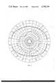
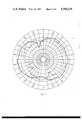
- FIGS. 4-9are series of antenna patterns characteristic of the present invention.
- the antenna orientationis such that the forward edge of the pod is aligned with 0 degrees.
- the scaleis decibels referenced to isotropic (dBi).
- the solid curveis for vertical polarization, with the weaker gain curves, indicated by dashed lines, indicating the pattern for horizontal polarization.
- FIGS. 4-6are measurements of the azimuthal plane, FIG. 4 being the pattern for the low end of the operating frequency range, FIG. 5 being in approximately the center of the range, and FIG. 6 being at the high end of the range.
- FIGS. 7, 8, and 9are measurements of the elevational plane, also showing low, middle, and high end of the frequency band covered, respectively.
- the antennaexhibits substantially omnidirectional characteristics in the vertical polarization mode across the operating frequency band.
Landscapes
- Physics & Mathematics (AREA)
- Engineering & Computer Science (AREA)
- Remote Sensing (AREA)
- Fluid Mechanics (AREA)
- Astronomy & Astrophysics (AREA)
- Aviation & Aerospace Engineering (AREA)
- General Physics & Mathematics (AREA)
- Variable-Direction Aerials And Aerial Arrays (AREA)
- Details Of Aerials (AREA)
- Waveguide Aerials (AREA)
Abstract
Description
Claims (9)
Priority Applications (1)
| Application Number | Priority Date | Filing Date | Title |
|---|---|---|---|
| US06/773,699US4709239A (en) | 1985-09-09 | 1985-09-09 | Dipatch antenna |
Applications Claiming Priority (1)
| Application Number | Priority Date | Filing Date | Title |
|---|---|---|---|
| US06/773,699US4709239A (en) | 1985-09-09 | 1985-09-09 | Dipatch antenna |
Publications (1)
| Publication Number | Publication Date |
|---|---|
| US4709239Atrue US4709239A (en) | 1987-11-24 |
Family
ID=25099041
Family Applications (1)
| Application Number | Title | Priority Date | Filing Date |
|---|---|---|---|
| US06/773,699Expired - LifetimeUS4709239A (en) | 1985-09-09 | 1985-09-09 | Dipatch antenna |
Country Status (1)
| Country | Link |
|---|---|
| US (1) | US4709239A (en) |
Cited By (7)
| Publication number | Priority date | Publication date | Assignee | Title |
|---|---|---|---|---|
| US4922259A (en)* | 1988-02-04 | 1990-05-01 | Mcdonnell Douglas Corporation | Microstrip patch antenna with omni-directional radiation pattern |
| US5184141A (en)* | 1990-04-05 | 1993-02-02 | Vought Aircraft Company | Structurally-embedded electronics assembly |
| US5231407A (en)* | 1989-04-18 | 1993-07-27 | Novatel Communications, Ltd. | Duplexing antenna for portable radio transceiver |
| US6218995B1 (en) | 1997-06-13 | 2001-04-17 | Itron, Inc. | Telemetry antenna system |
| US6262685B1 (en) | 1997-10-24 | 2001-07-17 | Itron, Inc. | Passive radiator |
| US7015868B2 (en) | 1999-09-20 | 2006-03-21 | Fractus, S.A. | Multilevel Antennae |
| US10915152B2 (en)* | 2016-04-26 | 2021-02-09 | Src, Inc. | Scalable high-performance embedded computing systems |
Citations (10)
| Publication number | Priority date | Publication date | Assignee | Title |
|---|---|---|---|---|
| US3665480A (en)* | 1969-01-23 | 1972-05-23 | Raytheon Co | Annular slot antenna with stripline feed |
| US3921177A (en)* | 1973-04-17 | 1975-11-18 | Ball Brothers Res Corp | Microstrip antenna structures and arrays |
| US4051480A (en)* | 1976-10-27 | 1977-09-27 | The United States Of America As Represented By The Secretary Of The Army | Conformal edge-slot radiators |
| US4053895A (en)* | 1976-11-24 | 1977-10-11 | The United States Of America As Represented By The Secretary Of The Air Force | Electronically scanned microstrip antenna array |
| US4167010A (en)* | 1978-03-13 | 1979-09-04 | The United States Of America As Represented By The Secretary Of The Army | Terminated microstrip antenna |
| US4210793A (en)* | 1978-03-06 | 1980-07-01 | Agence Nationale De Valorisation De La Recherche (Anvar) | Microwave applicator for radiating microwaves to an elongated zone |
| US4259670A (en)* | 1978-05-16 | 1981-03-31 | Ball Corporation | Broadband microstrip antenna with automatically progressively shortened resonant dimensions with respect to increasing frequency of operation |
| US4367474A (en)* | 1980-08-05 | 1983-01-04 | The United States Of America As Represented By The Secretary Of The Army | Frequency-agile, polarization diverse microstrip antennas and frequency scanned arrays |
| US4379296A (en)* | 1980-10-20 | 1983-04-05 | The United States Of America As Represented By The Secretary Of The Army | Selectable-mode microstrip antenna and selectable-mode microstrip antenna arrays |
| US4410891A (en)* | 1979-12-14 | 1983-10-18 | The United States Of America As Represented By The Secretary Of The Army | Microstrip antenna with polarization diversity |
- 1985
- 1985-09-09USUS06/773,699patent/US4709239A/ennot_activeExpired - Lifetime
Patent Citations (10)
| Publication number | Priority date | Publication date | Assignee | Title |
|---|---|---|---|---|
| US3665480A (en)* | 1969-01-23 | 1972-05-23 | Raytheon Co | Annular slot antenna with stripline feed |
| US3921177A (en)* | 1973-04-17 | 1975-11-18 | Ball Brothers Res Corp | Microstrip antenna structures and arrays |
| US4051480A (en)* | 1976-10-27 | 1977-09-27 | The United States Of America As Represented By The Secretary Of The Army | Conformal edge-slot radiators |
| US4053895A (en)* | 1976-11-24 | 1977-10-11 | The United States Of America As Represented By The Secretary Of The Air Force | Electronically scanned microstrip antenna array |
| US4210793A (en)* | 1978-03-06 | 1980-07-01 | Agence Nationale De Valorisation De La Recherche (Anvar) | Microwave applicator for radiating microwaves to an elongated zone |
| US4167010A (en)* | 1978-03-13 | 1979-09-04 | The United States Of America As Represented By The Secretary Of The Army | Terminated microstrip antenna |
| US4259670A (en)* | 1978-05-16 | 1981-03-31 | Ball Corporation | Broadband microstrip antenna with automatically progressively shortened resonant dimensions with respect to increasing frequency of operation |
| US4410891A (en)* | 1979-12-14 | 1983-10-18 | The United States Of America As Represented By The Secretary Of The Army | Microstrip antenna with polarization diversity |
| US4367474A (en)* | 1980-08-05 | 1983-01-04 | The United States Of America As Represented By The Secretary Of The Army | Frequency-agile, polarization diverse microstrip antennas and frequency scanned arrays |
| US4379296A (en)* | 1980-10-20 | 1983-04-05 | The United States Of America As Represented By The Secretary Of The Army | Selectable-mode microstrip antenna and selectable-mode microstrip antenna arrays |
Non-Patent Citations (4)
| Title |
|---|
| D. H. Schaubert, F. G. Farrar, Arthur Sindoris, and S. T. Hayes; "Microstrip Antennas with Frequency Agility and Polarization Diversity", IEEE Transactions on Antennas and Propagation, vol. AP-29, No. 1, Jan. 1981, pp. 118-123. |
| D. H. Schaubert, F. G. Farrar, Arthur Sindoris, and S. T. Hayes; Microstrip Antennas with Frequency Agility and Polarization Diversity , IEEE Transactions on Antennas and Propagation, vol. AP 29, No. 1, Jan. 1981, pp. 118 123.* |
| D. H. Schaubert, H. S. Jones, and F. Reggia; "Conformal Dielectric-Filled Edge-Slot Antennas with Inductive-Post Tuning", IEEE Transactions on Antennas and Propagation, vol. AP-27, No. 5, Sep. 1979, pp. 713 through 716. |
| D. H. Schaubert, H. S. Jones, and F. Reggia; Conformal Dielectric Filled Edge Slot Antennas with Inductive Post Tuning , IEEE Transactions on Antennas and Propagation, vol. AP 27, No. 5, Sep. 1979, pp. 713 through 716.* |
Cited By (28)
| Publication number | Priority date | Publication date | Assignee | Title |
|---|---|---|---|---|
| US4922259A (en)* | 1988-02-04 | 1990-05-01 | Mcdonnell Douglas Corporation | Microstrip patch antenna with omni-directional radiation pattern |
| US5231407A (en)* | 1989-04-18 | 1993-07-27 | Novatel Communications, Ltd. | Duplexing antenna for portable radio transceiver |
| US5184141A (en)* | 1990-04-05 | 1993-02-02 | Vought Aircraft Company | Structurally-embedded electronics assembly |
| US6218995B1 (en) | 1997-06-13 | 2001-04-17 | Itron, Inc. | Telemetry antenna system |
| US6262685B1 (en) | 1997-10-24 | 2001-07-17 | Itron, Inc. | Passive radiator |
| US20110175777A1 (en)* | 1999-09-20 | 2011-07-21 | Fractus, S.A. | Multilevel antennae |
| US8154463B2 (en) | 1999-09-20 | 2012-04-10 | Fractus, S.A. | Multilevel antennae |
| US20070194992A1 (en)* | 1999-09-20 | 2007-08-23 | Fractus, S.A. | Multi-level antennae |
| US20080042909A1 (en)* | 1999-09-20 | 2008-02-21 | Fractus, S.A. | Multilevel antennae |
| US7394432B2 (en) | 1999-09-20 | 2008-07-01 | Fractus, S.A. | Multilevel antenna |
| US7397431B2 (en) | 1999-09-20 | 2008-07-08 | Fractus, S.A. | Multilevel antennae |
| US7505007B2 (en) | 1999-09-20 | 2009-03-17 | Fractus, S.A. | Multi-level antennae |
| US7528782B2 (en) | 1999-09-20 | 2009-05-05 | Fractus, S.A. | Multilevel antennae |
| US20110163923A1 (en)* | 1999-09-20 | 2011-07-07 | Fractus, S.A. | Multilevel antennae |
| US7015868B2 (en) | 1999-09-20 | 2006-03-21 | Fractus, S.A. | Multilevel Antennae |
| US8009111B2 (en) | 1999-09-20 | 2011-08-30 | Fractus, S.A. | Multilevel antennae |
| US7123208B2 (en) | 1999-09-20 | 2006-10-17 | Fractus, S.A. | Multilevel antennae |
| US8154462B2 (en) | 1999-09-20 | 2012-04-10 | Fractus, S.A. | Multilevel antennae |
| US8330659B2 (en) | 1999-09-20 | 2012-12-11 | Fractus, S.A. | Multilevel antennae |
| US8941541B2 (en) | 1999-09-20 | 2015-01-27 | Fractus, S.A. | Multilevel antennae |
| US8976069B2 (en) | 1999-09-20 | 2015-03-10 | Fractus, S.A. | Multilevel antennae |
| US9000985B2 (en) | 1999-09-20 | 2015-04-07 | Fractus, S.A. | Multilevel antennae |
| US9054421B2 (en) | 1999-09-20 | 2015-06-09 | Fractus, S.A. | Multilevel antennae |
| US9240632B2 (en) | 1999-09-20 | 2016-01-19 | Fractus, S.A. | Multilevel antennae |
| US9362617B2 (en) | 1999-09-20 | 2016-06-07 | Fractus, S.A. | Multilevel antennae |
| US9761934B2 (en) | 1999-09-20 | 2017-09-12 | Fractus, S.A. | Multilevel antennae |
| US10056682B2 (en) | 1999-09-20 | 2018-08-21 | Fractus, S.A. | Multilevel antennae |
| US10915152B2 (en)* | 2016-04-26 | 2021-02-09 | Src, Inc. | Scalable high-performance embedded computing systems |
Similar Documents
| Publication | Publication Date | Title |
|---|---|---|
| US5307075A (en) | Directional microstrip antenna with stacked planar elements | |
| US5121127A (en) | Microstrip antenna | |
| EP0716774B1 (en) | A folded dipole antenna | |
| US4367474A (en) | Frequency-agile, polarization diverse microstrip antennas and frequency scanned arrays | |
| EP0172626B1 (en) | Adaptive array antenna | |
| US4410891A (en) | Microstrip antenna with polarization diversity | |
| US3718935A (en) | Dual circularly polarized phased array antenna | |
| US3803623A (en) | Microstrip antenna | |
| US4814777A (en) | Dual-polarization, omni-directional antenna system | |
| US4605933A (en) | Extended bandwidth microstrip antenna | |
| EP2984709B1 (en) | Array antenna and related techniques | |
| US4870426A (en) | Dual band antenna element | |
| US3987455A (en) | Microstrip antenna | |
| US6061031A (en) | Method and apparatus for a dual frequency band antenna | |
| US5270722A (en) | Patch-type microwave antenna | |
| CN110233335A (en) | Miniaturization low section dual polarized antenna based on artificial magnetic conductor | |
| US10069208B2 (en) | Dual-frequency patch antenna | |
| US4127857A (en) | Radio frequency antenna with combined lens and polarizer | |
| EP3799203A1 (en) | Radiating elements having parasitic elements for increased isolation and base station antennas including such radiating elements | |
| US6384792B2 (en) | Narrowband/wideband dual mode antenna | |
| US11764475B2 (en) | High gain and fan beam antenna structures and associated antenna-in-package | |
| US6342868B1 (en) | Stripline PCB dipole antenna | |
| US20020047802A1 (en) | Patch antenna device | |
| US4516127A (en) | Three element low profile antenna | |
| US4709239A (en) | Dipatch antenna |
Legal Events
| Date | Code | Title | Description |
|---|---|---|---|
| AS | Assignment | Owner name:SANDERS ASSOCIATES, INC., DANIEL WEBSTER HIGHWAY S Free format text:ASSIGNMENT OF ASSIGNORS INTEREST.;ASSIGNOR:HERRICK, DAVID L.;REEL/FRAME:004459/0608 Effective date:19850905 | |
| STCF | Information on status: patent grant | Free format text:PATENTED CASE | |
| FEPP | Fee payment procedure | Free format text:PAYOR NUMBER ASSIGNED (ORIGINAL EVENT CODE: ASPN); ENTITY STATUS OF PATENT OWNER: LARGE ENTITY | |
| FPAY | Fee payment | Year of fee payment:4 | |
| FPAY | Fee payment | Year of fee payment:8 | |
| AS | Assignment | Owner name:LOCKHEED SANDERS, INC., MARYLAND Free format text:CHANGE OF NAME;ASSIGNOR:SANDERS ASSOCIATES, INC.;REEL/FRAME:009570/0883 Effective date:19900109 | |
| FPAY | Fee payment | Year of fee payment:12 | |
| AS | Assignment | Owner name:LOCKHEED CORPORATION, MARYLAND Free format text:MERGER;ASSIGNOR:LOCKHEED SANDERS, INC.;REEL/FRAME:010859/0486 Effective date:19960125 | |
| AS | Assignment | Owner name:LOCKHEED MARTIN CORPORATION, MARYLAND Free format text:MERGER;ASSIGNOR:LOCKHEED CORPORATION;REEL/FRAME:010871/0442 Effective date:19960128 | |
| AS | Assignment | Owner name:EAST WEST BANK, CALIFORNIA Free format text:SECURITY INTEREST;ASSIGNOR:SKYCROSS, INC.;REEL/FRAME:030539/0601 Effective date:20130325 | |
| AS | Assignment | Owner name:HERCULES TECHNOLOGY GROWTH CAPITAL, INC., CALIFORN Free format text:SECURITY INTEREST;ASSIGNOR:SKYCROSS, INC.;REEL/FRAME:033244/0853 Effective date:20140625 | |
| AS | Assignment | Owner name:ACHILLES TECHNOLOGY MANAGEMENT CO II, INC., CALIFO Free format text:SECURED PARTY BILL OF SALE AND ASSIGNMENT;ASSIGNOR:HERCULES CAPITAL, INC.;REEL/FRAME:039114/0803 Effective date:20160620 | |
| AS | Assignment | Owner name:SKYCROSS, INC., CALIFORNIA Free format text:RELEASE BY SECURED PARTY;ASSIGNOR:EAST WEST BANK;REEL/FRAME:040145/0883 Effective date:20160907 |